EP3826558B1 - Cellulitebehandlungssystem - Google Patents
Cellulitebehandlungssystem Download PDFInfo
- Publication number
- EP3826558B1 EP3826558B1 EP19841959.0A EP19841959A EP3826558B1 EP 3826558 B1 EP3826558 B1 EP 3826558B1 EP 19841959 A EP19841959 A EP 19841959A EP 3826558 B1 EP3826558 B1 EP 3826558B1
- Authority
- EP
- European Patent Office
- Prior art keywords
- septa
- treatment
- cellulite
- engaging
- blade
- Prior art date
- Legal status (The legal status is an assumption and is not a legal conclusion. Google has not performed a legal analysis and makes no representation as to the accuracy of the status listed.)
- Active
Links
Images


Classifications
-
- A—HUMAN NECESSITIES
- A61—MEDICAL OR VETERINARY SCIENCE; HYGIENE
- A61B—DIAGNOSIS; SURGERY; IDENTIFICATION
- A61B17/00—Surgical instruments, devices or methods
- A61B17/32—Surgical cutting instruments
- A61B17/320016—Endoscopic cutting instruments, e.g. arthroscopes, resectoscopes
-
- A—HUMAN NECESSITIES
- A61—MEDICAL OR VETERINARY SCIENCE; HYGIENE
- A61B—DIAGNOSIS; SURGERY; IDENTIFICATION
- A61B1/00—Instruments for performing medical examinations of the interior of cavities or tubes of the body by visual or photographical inspection, e.g. endoscopes; Illuminating arrangements therefor
- A61B1/06—Instruments for performing medical examinations of the interior of cavities or tubes of the body by visual or photographical inspection, e.g. endoscopes; Illuminating arrangements therefor with illuminating arrangements
-
- A—HUMAN NECESSITIES
- A61—MEDICAL OR VETERINARY SCIENCE; HYGIENE
- A61B—DIAGNOSIS; SURGERY; IDENTIFICATION
- A61B17/00—Surgical instruments, devices or methods
- A61B17/32—Surgical cutting instruments
-
- A—HUMAN NECESSITIES
- A61—MEDICAL OR VETERINARY SCIENCE; HYGIENE
- A61B—DIAGNOSIS; SURGERY; IDENTIFICATION
- A61B17/00—Surgical instruments, devices or methods
- A61B17/32—Surgical cutting instruments
- A61B17/320016—Endoscopic cutting instruments, e.g. arthroscopes, resectoscopes
- A61B17/320036—Endoscopic cutting instruments, e.g. arthroscopes, resectoscopes adapted for use within the carpal tunnel
-
- A—HUMAN NECESSITIES
- A61—MEDICAL OR VETERINARY SCIENCE; HYGIENE
- A61B—DIAGNOSIS; SURGERY; IDENTIFICATION
- A61B17/00—Surgical instruments, devices or methods
- A61B17/32—Surgical cutting instruments
- A61B17/3201—Scissors
-
- A—HUMAN NECESSITIES
- A61—MEDICAL OR VETERINARY SCIENCE; HYGIENE
- A61B—DIAGNOSIS; SURGERY; IDENTIFICATION
- A61B17/00—Surgical instruments, devices or methods
- A61B17/32—Surgical cutting instruments
- A61B17/3205—Excision instruments
- A61B17/32056—Surgical snare instruments
-
- A—HUMAN NECESSITIES
- A61—MEDICAL OR VETERINARY SCIENCE; HYGIENE
- A61B—DIAGNOSIS; SURGERY; IDENTIFICATION
- A61B17/00—Surgical instruments, devices or methods
- A61B17/32—Surgical cutting instruments
- A61B17/3205—Excision instruments
- A61B17/3207—Atherectomy devices working by cutting or abrading; Similar devices specially adapted for non-vascular obstructions
- A61B17/320725—Atherectomy devices working by cutting or abrading; Similar devices specially adapted for non-vascular obstructions with radially expandable cutting or abrading elements
-
- A—HUMAN NECESSITIES
- A61—MEDICAL OR VETERINARY SCIENCE; HYGIENE
- A61B—DIAGNOSIS; SURGERY; IDENTIFICATION
- A61B17/00—Surgical instruments, devices or methods
- A61B2017/00743—Type of operation; Specification of treatment sites
- A61B2017/00747—Dermatology
-
- A—HUMAN NECESSITIES
- A61—MEDICAL OR VETERINARY SCIENCE; HYGIENE
- A61B—DIAGNOSIS; SURGERY; IDENTIFICATION
- A61B17/00—Surgical instruments, devices or methods
- A61B2017/00743—Type of operation; Specification of treatment sites
- A61B2017/00792—Plastic surgery
-
- A—HUMAN NECESSITIES
- A61—MEDICAL OR VETERINARY SCIENCE; HYGIENE
- A61B—DIAGNOSIS; SURGERY; IDENTIFICATION
- A61B17/00—Surgical instruments, devices or methods
- A61B17/32—Surgical cutting instruments
- A61B2017/320052—Guides for cutting instruments
-
- A—HUMAN NECESSITIES
- A61—MEDICAL OR VETERINARY SCIENCE; HYGIENE
- A61B—DIAGNOSIS; SURGERY; IDENTIFICATION
- A61B90/00—Instruments, implements or accessories specially adapted for surgery or diagnosis and not covered by any of the groups A61B1/00 - A61B50/00, e.g. for luxation treatment or for protecting wound edges
- A61B90/39—Markers, e.g. radio-opaque or breast lesions markers
- A61B2090/3937—Visible markers
- A61B2090/3945—Active visible markers, e.g. light emitting diodes
-
- A—HUMAN NECESSITIES
- A61—MEDICAL OR VETERINARY SCIENCE; HYGIENE
- A61B—DIAGNOSIS; SURGERY; IDENTIFICATION
- A61B90/00—Instruments, implements or accessories specially adapted for surgery or diagnosis and not covered by any of the groups A61B1/00 - A61B50/00, e.g. for luxation treatment or for protecting wound edges
- A61B90/39—Markers, e.g. radio-opaque or breast lesions markers
- A61B2090/3937—Visible markers
- A61B2090/395—Visible markers with marking agent for marking skin or other tissue
Definitions
- the present disclosure generally relates to systems and methods for treating cellulite.
- This application claims the benefit and priority of United States Patent Application Nos. 62/702,314 filed July 23, 2018 ; 62/736,016 filed September 25, 2018 ; 62/798,515 filed January 30, 2019 ; 62/802,368 filed February 7, 2019 ; and 62/8254,447 filed March 28, 2019 .
- US 2010/057056 A1 discloses a device for performing liposuction surgery including a mechanical cutting element moveable between a stored and a cutting position.
- Subdermal fat layers below the epidermis are contained between dermal layers connected by septa which act as connective tissue between the dermal layers.
- the septa are arranged more randomly and densely oriented in a more criss-crossed configuration while the septa in women are generally more parallel in arrangement.
- men have thicker dermis and more angled septa relative to the skin surface whereas women have relatively thinner dermis which thins with age, and septa that are perpendicular to the skin surface.
- women with cellulite have exhibited thickening of the septa in the regions of cellulite and tensioning of septa highlights cellulite.
- adipose tissue In women, fat storage in adipose tissue has a biological purpose in that it is maximized ensuring adequate caloric availability for pregnancy and lactation.
- An increase in fluid retention or proliferation of adipose tissue in such subdermal fat layers can further result in the appearance of cellulite where the septa is maintaining a first distance between dermal layers, thus creating dimples, whereas pockets between septa bulge. Over time, the septa may stretch, then eventually contract and harden thus retaining tissue layers at fixed distances, but pockets between such septa may be expanded thus adding to the appearance of cellulite.
- the cellulite treatment apparatus according to the invention is defined in claim 1. Preferred embodiments are defined in the dependent claims. The surgical methods discloses herein are not claimed.
- the present disclosure is directed towards cellulite treatment systems and methods involving an apparatus that facilitates and methods involving, depending on the system used and force applied by the user, stretching, re-orienting, disrupting, cutting, slicing, and/or tearing septum or septa in a location of cellulite.
- the treatment approach involves a tissue cutting or slicing system.
- a cellulite treatment device is mounted at a distal end portion of a shaft and is sized and shaped to be advanced between tissue layers.
- fibrous septa that connect superior and inferior fascia plateaus within skin can be crossed with the treatment device using one or more of an array of tools to engage, and depending on the tool used and force applied by the user, stretch, re-orient, tear, disrupt, cut or slice septa.
- a cellulite treatment system embodies a tool facilitating an ability to reach and treat all target cellulite appearance areas through a single or a limited number of entries through the skin.
- such tool is sized, shaped and configured (e.g. less than or equal to about two millimeters diameter and blunt dissection tip) to be placed within and advanced between tissue layers on its own and without assistance from external skin stabilizing structure, such as a suction device. Entry points through the skin such as high on the hip under where a bikini or underwear strap would be and along creases or transitions between buttocks and thighs are employed.
- septa causing a dimple or depression are located at various angles and locations relative to the dimple or depression observed on the skin and are not necessarily directly below such expressions of cellulite, and the treatment system and method is configured to identify the septa responsible for the appearance of cellulite that has been marked on the skin and target treatment on those septa and leave adjacent septa, blood vessels, etc. intact. Moreover, a range such as a small subset or a larger number of septa can be the structure causing a particular depression or dimple.
- anesthetic is injected into the treatment site transcutaneously or subcutaneously, a cellulite treatment system is inserted subcutaneously across the treatment site and used to identify the septa responsible for a depression or dimple by pushing or pulling on various septa to cause a depression in the skin in the target area, and a cutting or slicing device or septa disruption structure is placed subcutaneously at the treatment site and employed to engage and cut or slice or break the septa tissue.
- the patient is directed to clench their buttocks and/or leg muscles to help facilitate identifying target areas and after septa treatment confirm release of septa that create dimples or depressions.
- the physician can press in a cranial to caudal direction on the skin above the treatment target or pull from below the treatment target.
- Remote imaging or ultrasonic or fluoroscopic energy can be employed to observe the procedure.
- a resizing or alternative configuration of the treatment structure can be employed to complete the treatment of a particular area.
- the treatment device is then repositioned to treat additional areas.
- the treatment device can be configured to treat a plurality of areas simultaneously or in succession without removing from the patient or a spot treatment approach can be taken. Langer lines can be employed as a reference to direct treatment. Additionally, through one or more entry points, various treatment trajectories are directed and in certain applications a steerable introducer is used to access treatment areas.
- anti-inflammatory, collagenase, deoxycholic acid, salicylic acid, glycolic acid, hyaluronic acid or cellulite treatment medicants can be employed at the interventional site separately or directly by the interventional device or other procedural instrumentation. Aspects of the current disclosure include specific identification of the septa responsible for the cellulite appearance, severing or separation of those septa, confirmation intra-operatively of the separation of those septa was accomplished and the prevention of the re-appearance of the cellulite.
- the treatment device can include one or more of blunt tipped scissors, a guillotine-type angled blade, projecting linkages, side opening hooks or V-shaped structure, an internal hook, a bevel hook, a rotating structure or blade, a cutting balloon or harmonic scalpel, selective cautery structure or energy transmitting structure for disrupting, cutting, slicing or dissecting tissue and/or controlling bleeding.
- the treatment device includes a mechanical septa cutting element, such as a blade or sharpened surface, that cooperates with a septa hooking element to both hook then cut, slice, tear or disrupt septa.
- One or more of the septa hooking element and the septa cutting element is convertible from a hooking configuration to a cutting configuration and from a cutting configuration to a hooking configuration or to a stored configuration.
- the treatment device is embodied in an elongate member insertable through the skin capable of expanding at least one region from a smaller state to a wider state, and when in the wider state is configurable to both hook and cut, slice or disrupt target septa.
- cutting or disruption is accomplished with electrical or thermal means such as mono-polar or bi-polar structures or a hot wire configured to address bleeding and ease cutting.
- the cellulite treatment system also involves in certain approaches, illumination such as a bright light configured at or emitted through a tip of treatment structure or placed along or at strategic locations along treatment structure for the purposes of tracking advancement of the tool to the treatment site and locating intradermal structures at the treatment site.
- illumination such as a bright light configured at or emitted through a tip of treatment structure or placed along or at strategic locations along treatment structure for the purposes of tracking advancement of the tool to the treatment site and locating intradermal structures at the treatment site.
- objective measurement devices are included in the treatment system to assess the results of therapy.
- laser light energy such as bright light or laser light is emitted and received by the measurement device and surfaces of treated areas is scanned.
- the measurement device creates a complete three-dimensional map of all cellulite relative to normal skin. By comparing improvement of volume of divots versus normal idealized surfaces, the operator can calculate total and local volume benefits of therapy and track improvement over time.
- the disclosed devices and structures are employed for body sculpting, eliminating wrinkles, treating acne scars and/or repositioning skin.
- Foam fillers or spacers of varying lengths and other structures such as subcutaneous attachment structures that are absorbable or permanent are used to accomplish such objectives.
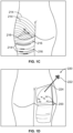
- Figs. 1A-B there is shown a person exhibiting cellulite 200 about their thighs and buttocks.
- dimples and/or depressions characteristic of the cellulite 200 intended to be treated are identified or circled with markings 204, preferably while the patient is standing as for most patients the appearance of their cellulite disappears when they lie down on their stomach because gravity is pulling in a different direction.
- computerized imaging equipment is used to locate and mark dimples and/or depressions.
- Figs. 1A-B forty-four dimples and depressions are marked for possible treatment.
- the physician treating the patient determines an instrument insertion site 210 and paths 212 that most efficiently treat cellulite with a minimal amount of insertion sites and instrument paths under the skin.
- an instrument insertion site is chosen that is in a crease or fold of skin such as where the buttocks meets the thigh or in the crease between the two buttocks at a location that is not seen when the buttocks are in natural contact for improved cosmesis after the procedure healing period.
- the inner thigh is chosen as an insertion site as this location is less visual as it heals.
- Such treatment paths are selected by the operator preferably using a straight edge that bends or contours to the patient or can be generated automatically by employing a computerized controller programmed to most efficiently address and measure cellulite residing in a pre-defined treatment site.
- the computerized controller can be associated with a scanner that identifies specific dimples and areas for treatment such as by employing laser technology.
- the computerized controller includes a program specific to cellulite treatment and is used in conjunction with an electronic and mechanical device and comprises or includes a non-transitory computer-readable storage medium and a computer-program mechanism embedded therein to both identify treatment areas and to plot primary and alternative approaches to treatments.
- computerized visualization and treatment planning equipment is used to assist the physician in determining insertion site locations and paths to be taken to the marked targets.
- the patient lies down on their stomach on the treatment table.
- a patient can be treated while standing, particularly for a small number of treatment targets, or while standing and leaning forward on a support and alternatively between standing and leaning forward so that gravity can help identify and confirm treatment of the targeted septa.
- the measurement device creates a complete three-dimensional map of all cellulite relative to normal skin. By dating and comparing improvement of volume of divots or dimples versus normal idealized surfaces, the operator calculates total and local volume benefits of therapy and track improvement over time.
- the cellulite treatment follows or references Langer lines 214 existing in tissue.
- Langer lines 214 correspond to natural orientations of tissue fibers that exist in humans, and have been recognized as being generally parallel to the orientation of muscle fibers.
- the Langer lines 214 can be used as a reference to treat cellulite.
- cellulite appears to be related to and fall along the locations of Langer lines.
- multiple treatment targets along Langer lines are treated from a single entry 216, the Langer lines 214 providing a map along which treatment is accomplished.
- treatment can be directed along Langer lines 214 as shown on the thigh for illustrative purposes to treat targeted septa, or additionally or alternatively, treatment can be transverse to Langer lines 214 as shown on the buttock for illustrative purposes to treat targeted septa.
- Treatment can also be directed at various positions about connecting tissue or septa. That is, septa can be engaged, stretched, re-oriented, torn, cut, sliced, ruptured or disrupted from various sides or angles respecting septa. Thus, septa can be treated from above, below or the sides of septa to achieve the best results.
- treatment can be most effective from above a particular connecting tissue to take advantage of gravity where treatment forces placed on the connecting tissue coincide with the direction of gravity or the direction that gravity most often works on a standing body, as it has been observed that cellulite is often most visible in a standing individual.
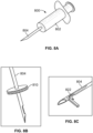
- a cellulite treatment assembly 220 including a handle 222 and an elongate member or needle-sized structure preferably two millimeters or less in diameter, like structure 224 extending longitudinally therefrom.
- a force gauge (electronic or mechanical) can be provided to ensure that a pre-determined amount of force would be applied to the tissue when testing the septa to prevent over or under pulling.
- a treatment device 225 capable of one or more of engaging, stretching, slicing, cutting or disrupting connective tissue is configured at a distal end portion of the elongate member 224 (e.g., Figs. 1E-N ).
- All cutting means can be combined with or further energized with RF, a laser, ultrasonic or thermal energy to produce cutting and coagulation together or separately.
- Such locations are characterized in that they can be easily hidden either naturally or by clothing.
- Treatment targets, depressions and dimples that have been marked on the skin surface while the patient is standing often go away when the patient lies down on their stomach because gravity acts on the skin and underlying connective tissue in a different direction such that the ink mark is apparent but the dimple or depression is not.
- the disclosed interventional devices are configured such that a user can approach a target location and first use the interventional device to push, pull or otherwise tension septa in a target area under the skin to identify the specific septa impacting the target and/or which is the cause of the expression of cellulite. In other words, pulling or pushing on the septa under the skin to find the one(s) that create the dimple or depression in the skin surface.
- a user can approach a target location and first use the interventional device to push, pull or otherwise tension septa in a target area under the skin to identify the specific septa impacting the target and/or which is the cause of the expression of cellulite.
- pulling or pushing on the septa under the skin to find the one(s) that create the dimple or depression in the skin surface.
- taking an approach from an entry located inferior the treatment target advancing the end of the interventional device beyond the treatment target and then pulling inferiorly (effectively the "down" direction if the patient was standing) can provide a better approach, for example, for treatment targets on the leg,
- One or more strain gauges can be incorporated within the treatment device to help identify target septa as well as to assess the progress and completion of treating septa. This facilitates targeting of key septa in a less impactful way, ideally minimizing bruising or other issues associated with cutting or disrupting a large area around the target.
- various approaches to treating cellulite expressed as dimples or depressions 200 in the skin surface can be employed to create an indentation in skin through which interventional devices can be inserted subcutaneously.
- a treatment regimen is selected for inserting interventional instruments based upon the subject's anatomy as it relates to the septa 350 connecting tissue layers that define the chambers retaining fatty or other tissues.
- ultrasound can be used to assess the subcutaneous trajectory and depth of the various connective tissue bands responsible for the surface unevenness.
- the ultrasound evaluation can help with the particular trajectory selected for the desired depth.
- the ultrasound evaluation can also help with positioning the distal end portion of the treatment instrument strategically at the connection point between the connective tissue and the dermis or the facia.
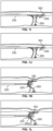
- targeted locations of cellulite 200 to be treated are marked 204 on the surface of the skin. This can be done when the patient is standing to best see cellulite. As shown schematically in Fig. 1F , cellulite can diminish or disappear when an individual is laying down, and should this happen, the marks identify and confirm their locations.
- a distal end portion of a cellulite treatment assembly 220 is inserted through the skin and the blunt tip is guided up into close proximity of the dermis as the tip can be tracked as it is advanced toward septa 350 ( Fig. 1G ) near the marked location 204.
- the inventors have discovered given the elasticity of septa 350, the distance from the marked location 204 to where the treatment assembly 220 is inserted into the skin is preferably at least about 2 cm so that there is enough distance to pull and disrupt septa 350 and not have the tip of the cellulite treatment assembly exit the skin in the process.
- the cellulite treatment assembly or other tool with a sharpened or blunt tip is inserted through the skin, advanced between subcutaneous tissue layers and toward septa 350.
- a distal end portion of the cellulite treatment assembly is configured with an illuminated tip 352 with enough brightness to be seen through the skin.
- the intensity of light emitted by the tip 352 can be set to a specific constant level such that at the preferred depth below the skin for severing or otherwise engaging septa 350, the light that appears at the level of the skin as a circle or projection is of a pre-determined size.
- the treatment device is advanced to the target site.
- the user adjusts the depth of the tip of the treatment tool such that the circle or projection of light is the pre-determined size.
- the septa 350 is tested and if confirmed as a target for treatment, the septa 350 is treated while maintaining the circle or projection at the pre-determined size.
- the user can also use the size of the circle or projection of light to maintain the depth of the tip of the treatment tool as it is advanced under the skin to the treatment target.
- a sharpened tip is employed to create access to target tissue thus allowing the tool to create the desired path both into tissue as well as between tissue layers. It is expected that the depth that these tools are advanced will be between about 3 and about 10 mm below the skin surface, but it is anticipated that lesser and greater depths may also be optimal for a particular subject. In any event, the depth selected is chosen for cutting, slicing, disrupting, tearing, stretching or re-orienting of the subject's septa 350. Moreover, in one embodiment, it is to be appreciated that the device 220 is formed from a substantially rigid material so that a consistent plane below the skin surface is accessed.
- the tool is placed at a site below where cellulite (for example a dimple) is seen on the subject's skin.
- the treatment device is advanced through septa 350 and to where the treatment device 225 is in a position best suited to accomplish the identification of target septa and the cellulite removal or minimization treatment. As shown in Figs.
- the treatment device 225 is passed beyond septa 350, a hook is deployed and then pulled proximally to tension septa 350, such as by hooking the septa ( Fig. 1K ).
- the treatment device 225 is passed a few millimeters lateral, preferably about 1 to about 10 millimeters, more preferably about 3 to about 6 millimeters, and beyond the target location, a hook is deployed and then swept laterally toward the target followed by pulling proximally to hook and tension septa.
- transillumination can be employed to track the treatment device and guide the procedure.
- the marks 204 can facilitate targeting of septa 350 while using transillumination to see the location of the treatment device 225.
- a separate device can be employed to engage septa 350 to see if such septa are the source of a dimple or depression expressed on the outside of the skin.
- a secondary device can be placed remotely from the target (i.e. lesion) and configured to be capable of applying tension to the surface of skin in a predetermined direction so as to create the effect of gravity and produce the visualization of the lesions while the patient is in a prone position (i.e. a broad region of adhesive attached to a spring mechanism such that a predetermined force would be applied relatively parallel to the surface of the skin in the direction the skin would move when standing in gravity).
- a prone position i.e. a broad region of adhesive attached to a spring mechanism such that a predetermined force would be applied relatively parallel to the surface of the skin in the direction the skin would move when standing in gravity.
- a portion of the elongate member can be configured to transition from a smaller state to a wider or larger state, wherein in the wider or larger state a cutting surface (i.e. sharpened edge or energy) is presented to cut tissue, the device being sized and shaped to be inserted through the skin and engage one or more regions of septa subcutaneously.
- a cutting surface i.e. sharpened edge or energy
- septa causing a dimple or depression may be coming from various angles and locations relative to the dimple or depression seen on the skin rather than being directly below the dimple or depression, and may be due to one or only a few septa or a large number of septa that remotely cause the depression or dimple. Thus, so engaging certain septa will be reflected in some change in the dimple or depression on the skin.
- a determination is made concerning the correspondence with marks 204 made on the skin and the dimples being formed or re-formed. If the initial septa 350 that the user presses on or pulls on using the tool do not recreate a dimple or depression in the marked area 204, then the user releases those initial septa that were engaged and repositions the tool at different septa and presses on or pulls again.
- the tool 225 is manipulated to cut, slice, disrupt, re-orient, stretch or tear septum 350 connecting tissue layers.
- a blade 353 is deployed and presented for treatment ( Fig. 1L ).
- a balloon (not shown) is inflated to disrupt the septa.
- the treatment element 225 is moved back to its initial collapsed configuration.
- the treatment element is then advanced beyond the marked treatment location, the treatment element (e.g., hook) is deployed and then pulled back under the marked treatment location to confirm that all of the septa responsible for causing the marked dimple or depression have been separated intra-operatively. If they have not been, the tool is manipulated to cut, slice, disrupt, stretch, re-orient or tear additional septa. The steps are repeated until all of the septa responsible for creating the marked dimple or depression have been severed or sufficiently stretched and the dimple or depression cannot be re-created intra-operatively using the tool.
- Such manipulation results in selective rupture, tearing, cutting or slicing of targeted septum 350, and the removal or minimization of dimples and the expression of cellulite on skin ( Fig. 1M ).
- the treatment element e.g., hook and/or blade
- the tool 220 is removed from the site to be withdrawn from the body or repositioned in any direction along and within the target tissue plane to treat additional areas.
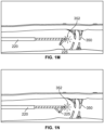
- a second light source 354 such as an LED (or other light source) is configured along the cellulite treatment assembly 220 proximal the illuminated tip 352 or alternatively, at the tip 352.
- a light source such as an LED chip can be configured at the tip of or otherwise along the treatment device with an electrical wire running proximally for control by the operator, or the light source can be generated by a light fiber extending along the device or to the tip with the LED or light source is configured within a proximally located position such as a handle of the treatment device.
- the light sources 352, 354 when the cellulite treatment assembly 220 is placed within a first relatively shallow desired depth, the light sources 352, 354 appear spaced and define discrete patterns when viewing the light sources via transillumination through skin ( Fig. 1P ).
- the light sources 352, 354 overlap ( Fig. 1R ) due to the natural dispersion of light emitted from the light sources 352, 354.
- An operator of the treatment system can determine a depth of the cellulite treatment assembly 229 by noting the discrete patterns of light or the degree of overlap of light overlap, the dispersion of light emitted and intensity of the light emitted from the light sources 352, 354.
- the light sources 352, 354 can also be of a different color to aid in determining the orientation of the cellulite treatment system 220 within tissue through illumination.
- the second light source 354 can emit a red color, for example, while the illuminated tip 352 can emit white light, while noting any variation of colors can also be employed.
- the color of the light can change depending on the configuration of the treatment device, such as for example, the device can project a white or first color when sheathed or stowed and change to another color or second color when a portion of the device is deployed or before and after use such as when tissue is cut.
- a strain gauge can be configured to communicate and cooperate with the light source to sense loads placed on the treatment device during treatment to thereby facilitate a change in color of the light source and to signal the progress or completion of targeted treatment.
- the second light source 354 can be employed via transillumination through skin to locate the cellulite treatment system relative to a treatment target area. Another benefit of the second light source is that it can indicate to the user where the hook and blade are located relative to the target septa. Also, as the treatment tool is being pulled proximally through the treatment target area, the illuminated tip 352 lets the user know when the hook and blade have been pulled through the target area. It is further noted that the light sources 352, 354 can be positioned at various alternative locations along a treatment device, and can be spaced from each other by various amounts.
- the cellulite treatment system can include greater than two light sources of the same or dissimilar colors.
- different colors of light can be used to indicate that the state of the distal end of the instrument. For example, red light is used to indicate the hook and blade are inside the instrument for advancing under the skin, white light is then used to indicate the hook is deployed, and red light is then used to indicate when the blade is deployed.
- the same device can be employed to access tissue layers below other sites or depressions existing in skin.
- the device is capable of anesthetic delivery as needed or desired when progressing to additional or new locations.
- the system can further include structure permitting the assembly to be steerable to subcutaneous treatment sites.
- the device would be configured to define longitudinally flexible material, and the instrumentation would be steered to the desired position within tissue.
- the device has a stiffness that varies along its length.
- the treatment device is embodied in a deflectable catheter.
- the cellulite treatment system includes a squeezing tool that reproducibly applies lateral forces on the skin to emphasize the dimple or expression of cellulite so a before and after treatment effect can be obtained without requiring the patient to stand up and/or without having to remove the interventional tools.
- the squeezing tool can be embodied, for example, in a clamp with elongated feet on opposite sides thereof or includes four fingers that pull radially inward once deployed on the surface of the skin and activated over or adjacent the targeted cellulite region.
- the patient is directed to clench their buttocks and/or leg muscles while lying on the procedure table or while standing to both identify treatment sites as well as confirm treatment.
- a skin stabilizer such as a suction stabilizer, can be used to help control the depth at which the cellulite treatment tool is advanced under the skin and maintain the targeted location as the tool is advanced.
- blunt tipped scissors 360 that are configured at a distal end portion of a cellulite treatment assembly 220.
- the blunt tipped scissors 360 are advanced under the skin to a target and used to engage suspected septa.
- the treatment structure, here scissors 360 are manipulated to disrupt, cut or slice the septa.
- the scissors 360 are opened and septa is placed between its blades.
- the blades are advanced against or caused to be closed about the septa to thereby cut, slice or sever the septa, thus relieving the tension between tissue layers and eliminating or minimizing the appearance of the dimple or depression expression on the skin.
- Actuation of the scissors is accomplished from a proximal end of the treatment device such as by pulling a wire or advancing and pushing an elongate member associated with the scissor arrangement (not shown).
- Illumination can be provided by a light 362 configured proximal of the scissors 360 so that transillumination can be employed to track the location of the distal portion of the treatment assembly 220. Additionally, or alternatively, in each disclosed embodiment, illumination can be via a lightguide from an external light source or via one or more LEDs.
- Illumination aids the user both with locating the treatment device as well as proper depth placement as transillumination decreases with increasing tool depth.
- the amount of illumination is set to ensure proper depth of a treatment device or structure, the level of illumination targeted being adjusted for skin type, thickness, presence of fat and pigment.
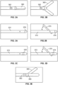
- the distal end portion of the cellulite treatment assembly can embody a side opening hook arm 370 that rotates with respect to a longitudinal shaft 372 to alternatively display septa engaging and/or septa cutting structure ( Figs. 3A-B ).
- the hook arm 370 is configured to swing out from a proximally directed, longitudinal configuration where it is parallel with the shaft 372 to a laterally projected configuration to thereby capture and tension septa once the device is advanced beyond the target location and then retracted.
- Figs. 3A-B transillumination functionality is provided by a light 376 configured at a terminal end of the device, whereas in the assembly shown in Figs.
- slits 378 formed in the shaft proximal the terminal end allow for the dispersion of light energy.
- cutting and septa engaging structure is embodied in a single moving arm 380, while illumination is provided proximal a hinge 382, but the same can be positioned at the terminal end of the device.
- the exposed edges of the arm 380 can be blunt or sharp for cutting or slicing.
- the arm 380 assumes a distally directed, longitudinal configuration parallel to the shaft 372 for advancement between tissue layers, and the arm 380 is caused to be projected laterally outwardly to both capture and cut or slice target septa. Actuation of the engaging and cutting structures can be accomplished through the manipulation of a proximally positioned lever or trigger connected to the same via a wire or longitudinally directed shaft (not shown). Once a desired area is treated, additional target areas can be addressed.
- the distal end portion of the cellulite treatment assembly 220 can alternatively or additionally embody an internal static hook 388 ( Fig. 4A ) to treat target areas from one or more skin insertion sites.
- a terminal end of the assembly or the hook itself 388 can be employed to be placed about tissue and to engage and test tissue to identify target septa. Sharpened edges within the hook can be used to engage and cut septa that has been targeted and identified as being associated with the expression of cellulite on the skin.
- a concentric sliding tube 390 actuatable from a proximal end of the cellulite treatment assembly can additionally be provided to be moved proximally and distally with respect to a hook 392.
- the tube 390 can include selectively sharpened edges or can be blunt to thus cooperate with the hook 392 to capture, cut, slice, tear or disrupt septa.
- the assembly can further be advanced in a spinning manner to cut or slice through septa. Employing the tube 390 to cut tissue results in a section being taken out of the septa as spaced cuts are simultaneous made through the septa.
- a cutting, slicing or disrupting assembly additionally or alternatively includes a longitudinally extendable and retractable sheath 393 that alternatively covers and exposes a hook 392, and further embodies an extendable and retractable guillotine-like blade 394.
- the blade 394 is sized and shaped to slide within an opening defined by the hook 392 and to cut tissues snared by the hook 392.
- the sheath 393 facilitates the assembly to define structure suited for advancement to a treatment site. Withdrawing the sheath 393 through manipulation of structure connected thereto positioned at a proximal end of the assembly, exposes the hook structure 392.
- the hook 392 is used to engage and capture target tissue to test if the targeted tissue is associated with the expression of cellulite on the skin. While the hook maintains the septa in a captured position, the guillotine blade 394 is advanced through manipulation of a proximally positioned actuator (not shown) to slice or cut captured septa to thereby eliminate or minimize the appearance of cellulite.
- a two-segment hook assembly 396, 397 is held together with a tensioning force (such as a spring or a wire or shaft connected thereto) on angled surfaces 398.
- a tensioning force such as a spring or a wire or shaft connected thereto
- an angle is formed between the two segments. It is to be recognized that the length of this hooked structure can be adjusted to fit a particular need. Further, selected edges of the hook assembly can be sharpened or be blunt.
- the hook can be covered in an elastomer such that as the elastomer is tensioned, the elastomer is displaced thus exposing the sharpened edges. When untensioned, the sharpened edges are safely encased.
- a spring-loaded shield can replace the elastomer.
- a cutting, slicing or disrupting treatment assembly is defined by a projecting linkage arrangement.
- a first link 400 includes a blade 401 and is rotatably attached at one end to a second link 402. The opposite end of the first link 400 slides with respect to a longitudinal shaft 405.
- a second end of the second link 402 is rotationally affixed to a distal point on the shaft 405.
- the links 400, 402 fully overlap ( Fig.
- the blade structure 401 is not exposed, but rather it is protected or covered by the second link 402.
- the drive shaft 407 is slightly retracted, thereby exposing the blade structure 401 to thereby present a sharp edge for cutting of hooked septa (See Fig. 7D ).
- the shaft 407 is withdrawn completely which results in the links 400, 402 assuming a co-linear and parallel relationship with the shaft.
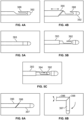
- the first link 400 defines a curved blade that is rotatably connected to a second link 402 that includes a generally triangular or pointed projection 408 that is sized and shaped to cover the blade 401 when the assembly is placed in a hooking configuration (See Fig. 7F ).
- the drive shaft 407 shown in phantom lines
- the blade 401 can be employed to cut septa.
- the drive shaft 407 is withdrawn so that the assembly defines a lower profile where the first 400 and second links 402 are generally longitudinally aligned ( Fig. 7E ).
- the rotatable connection between the first 400 and second links 402 can additionally or alternatively be characterized by a slotted arrangement 409.
- the projection 408 can be smaller, thus resulting in the overall profile of the treatment device being smaller.
- a septa hooking configuration ( Fig. 7J ) after pulling the drive shaft 407 proximally slightly, an end of the first link 400 resides in a proximal position within the slot 409 and the smaller projection 408 of the second link 402 overlays the blade 401.
- a septa cutting configuration Fig. 7K
- the end of the first link 400 assumes a distal position within the slot 409 such that the blade 401 is exposed for cutting.
- the first link 400 can also define a straight blade 401.
- the projection 408 is larger to therefore provide necessary coverage of the blade 401 when the device is placed in a hooking configuration ( Fig. 7M ).
- Each of the foregoing devices can also additionally or alternatively include other of the features disclosed herein such as structure providing transillumination and radiofrequency cutting and coagulation.
- a cellulite treatment system 940 (described in more detail in connection with Fig. 11 ) that can be employed to treat cellulite.
- a distal end portion of the treatment system 940 is configured with a treatment device 925.
- the treatment device of Figs. 7L-N is shown positioned at the distal end of the treatment device 940 in a hooking configuration ( Fig. 7P ). Any of the disclosed treatment devices can be so configured at the distal end of the treatment system 940.
- the treatment device can alternatively or additionally include a wire 410 that is rotatably attached to the second link 402.
- a proximal portion of the wire 410 serves as structure that can be advanced and retracted to configure the treatment device into closed, hooking and cutting positions.
- the wire 410 is formed into a coil 411 (See Fig. 7S ) that provides necessary strength and robustness for moving the wire 410 between closed ( Fig. 7Q ) and cutting ( Fig. 7S ) configurations.
- a septa hooking configuration Fig. 7R
- the second link 402 covers the wire 410 thereby prohibiting the wire to be exposed to target septa, and the coil 411 aligns with the second blade 402.
- the treatment device In its closed configuration ( Fig. 7Q ), the treatment device defines a low profile suited for being advanced to and between treatment targets.
- the proximally facing edge of the wire can be sharpened to produce a cutting edge.
- the wire can be an electrode attached to a radiofrequency generator so that the wire can be used for electrocautery or RF cutting of target tissue.
- the elongate member 224 of a cellulite treatment device can embody a tubular shape, including a lumen 412 extending therethrough, the lumen providing a space for a light fiber 414.
- the remaining space not occupied by the light fiber 414 defines a crescent moon shape from a cross-sectional view perspective.
- the tubular portion terminates at the treatment device 225.
- the lumen 412 of the elongate member 224 can be sized and shaped to individually receive one or more additional septa engaging, cutting, slicing or disrupting treatments devices 225 or for the injection of anesthetic, medications or other substances such as fillers or fat transfers before, during or after treatment.
- a treatment site can be dosed or filled with material contemporary with or during a treatment procedure rather than using a separate device and procedure to accomplish the same.
- each of the disclosed embodiments can be combined to provide a combination cellulite treatment assembly in a similar manner.
- spot treatment of septa is possible employing a cellulite treatment system 800 configured to address one interventional site at a time.
- cutting structures can be inserted perpendicular to skin to accomplish treatment or can be advanced below the skin in a direction generally parallel to the surface of the skin or angles with respect thereto.
- the structures of each of the disclosed tissue engaging and cutting devices can alternatively or additionally be configured to be used for treatment.
- the cutting action is rotary in character, such that cutter structure spins with controlled speeds configured to cut septa in a manner dictated by observed septa structure at the interventional site.
- the cutter is alternatively or additionally configured to accomplish cutting action by engaging or dragging the cutter against target septa.
- a system 800 includes an elongate handle 802 that is provided for grasping by an operator (See Figs. 8A-C ). Extending longitudinally from the handle 802 is a needle assembly 804. The needle 804 is configured to create an insertion site adjacent a specific cellulite target area, or directly into a dimple cellulite site. Further, it is through the needle assembly 804 that interventional site instrumentation is advanced to address and treat septa residing below a dimple expression on a subject's skin.
- a dilator can include or cooperate with a harmonic scalpel, selective cautery structure or energy transmitting structure for dissecting tissue and/or controlling bleeding.
- a cutting instrument is swept 360 degrees to cut surrounding septa.
- an endoscope can be employed in an assembly including a cutter to sever septa in a targeted manner. That is, septa that are viewed by the endoscope are targeted for severing by the cutter.
- direct visual confirmation of a treatment is provided.
- the needle 804 can be fashioned with a stop 810 that is positionable along the needle 804 as desired or dictated by a particular procedure or anatomy.
- the stop 810 is located so that when the needle 804 is placed within tissue, its terminal end is positioned at a desired depth such as between tissue layers connected by septa.
- a side opening 822 is further provided at the terminal end of the needle 804. It is through this side opening 822 that interventional devices such as cutters, scalpels, cautery structure or energy transmitting devices are advanced between tissue layers. Such devices are then employed to selectively treat the septa residing below the skin for the purpose of eliminating or reducing the appearance of cellulite. Once it is determined that the treatment has been successful, the spot cellulite treatment system 800 is then removed and employed at another location exhibiting cellulite.
- a treatment device can be equipped with a wire that includes linkages 830 manipulation of which function to push out a cutting blade 831 arrangement that is sized and shaped to cut connective tissue.
- a distal end portion of a spot treatment device can be equipped with a wire arranged to be advanceable to define a loop 832, the loop having a gauge facilitating the structure to be employed to cut tissue.
- RF energy can be employed to cut septa.
- FIG. 8F-G depicts a deformable hypotube 834 that is expandable such that two or more arms 836 project to define blades for cutting in another non-atraumatic approach to treatment.
- Fig. 8H illustrates a balloon structure 840 attached to a needle hypotube 842 which can be expanded below a dimple to eliminate or reduce the appearance of cellulite.
- a distal end portion of a spot treatment device can be fashioned with blades 850, one to cut for deployment and at least one that is configured to rotate and cut connective tissue.
- a dilator 410 can form a distal end portion of a cellulite treatment device and additionally be equipped with longitudinally extending blades 853 that are deployed when the dilator 410 is expanded.
- the blades 853 are configured to engage and cut target tissue or septa in an alternative approach to treatment. Such cutting is employed in an alternative to a non-traumatic approach and accomplished by rotating or otherwise advancing, sweeping or retracting the dilator 410.
- the assembly is unexpanded and withdrawn from the interventional site after use such as through a tube.
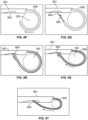
- a curved wire forming a lasso 859 and forming a distal end portion of a cellulite treatment assembly and being advanceable and retractable through a shaft 861 can be deployed about septa 350 within a target zone. Pulling the lasso 859 to reduce the perimeter it defines results in cutting septa 350 and treating cellulite.
- the lasso is formed from nitinol wire, or is pre-formed wire or pieces thereof. The lasso 859 encircles targeted septa and via tightening, cuts the septa.
- One approach involves cutting a targeted area without shaft movement thus providing a controlled approach to treatment.
- the lasso 859 can additionally or alternatively define a tube and the assembly can additionally include a wire 863 that is slidably configured within the tubular structure.
- the lasso structure 859 is partially configured about the septa 350 by pushing it out of shaft 861.
- the wire 863 is then advanced within the lasso 859 and out of a terminal end of the lasso 859 ( Fig. 8Q ).
- the wire 863 is then advanced toward a slot or opening 865 formed in the shaft 861 and is retained therein. Thereafter, the lasso 859 is further advanced to and into engagement with the shaft 861 to thereby define a completed hoop or loop ( Fig. 8R ).
- the lasso 859 is then pulled tight about the target septa 350 to cut, slice or disrupt the septa as desired ( Fig. 8T ).
- the completed hoop can remain in its larger hooped configuration and the entire device can be pulled proximally to slice or disrupt the encircled septa.
- the lasso 859 and wire 863 are pulled proximally through the shaft 861 so that they disengage from the slot 865 and are withdrawn completely or partially within the shaft 861 so that the treatment device can be used in additional locations.
- a pair of elongate tubes 867, 868 configurable in a generally parallel arrangement about target septa 350.
- the lasso 859 is advanced within the first tube 867 and out a terminal end thereof and toward the second tube 868 ( Fig. 8U ).
- the lasso 859 is then captured by the second tube 868 so that the treatment device encircles target septa 350.
- the assembly is then pulled proximally to cut, slice or disrupt target tissue.
- the lasso 859 is withdrawn within the first tube 867 and released from engagement with the second tube 868.
- the assembly is then positioned as necessary to treat additional areas.
- An atherectomy-style cutter 902 (See Figs. 9A-B ) also can be alternatively or additionally configured to remove tissue through an opening 904 on the side of the instrument, can be used in certain ancillary, more traumatic approaches to treatment.
- Cutting structure 906 is attached to an elongate actuator 908 via a block or other connection 910. Manipulation of the actuator 908 causes the cutting structure 906 to engage targeted tissue.
- a lumen 912 is further provided as a conduit for applying a suction force to the interventional site so that severed or macerated tissue 912 can be removed.
- This device can be employed to harvest fat for subsequent placement at a site that has been treated with a dilator and used to fill the space created.
- the cutter 902 can also be employed as a primary treatment device for cutting septa to treat cellulite.
- a treatment system 920 that can be used in connection with one or more of the previously described devices for treating target tissue.
- the treatment system 920 includes a handle 922 and an elongate member 924 extending longitudinally from the handle 922.
- a force gauge or sensor electro or mechanical
- a treatment device 925 capable of one or more of engaging, slicing, cutting or disrupting connective tissue is configured at a distal end portion of the elongate member 924.
- any one or more of the treatment devices described herein can define the treatment device 925. All cutting means can be combined with or further energized with RF, a laser, ultrasonic or thermal energy to produce cutting and coagulation together or separately.
- the handle 922 is equipped with a button or sliding trigger 926 that is configured to slide along a top surface of the handle 922.
- the trigger 926 is attached to a proximal end portion of a shaft or wire 928, a distal end portion of which is associated with or attached to the treatment device 925.
- the trigger 926 In a closed configuration, the trigger 926 is positioned in its most proximal position ( Fig. 10A ), and the treatment device 925 maintains a generally longitudinally aligned configuration.
- the treatment system 920 can be positioned or re-positioned to accomplish desired cellulite treatments.
- Moving the trigger 926 to its most distal position causes the shaft or wire 928 to advance distally and place the treatment device 925, for example, in a configuration for hooking target tissue ( Fig. 10B ).
- Withdrawing the trigger 926 to an intermediate position exposes a cutting structure (such as a blade or cutting wire) to thereby configure the treatment device 925 for cutting, slicing or disrupting target tissue ( Fig. 10C ).
- Detents or other cooperating structure can be incorporated into the handle or trigger to secure the trigger in one or more positions as well as to provide a tactile feedback regarding positioning.
- the system 925 can alternatively or additionally include any of the previously described functionality such as structure for providing transillumination and radiofrequency cutting and coagulation.
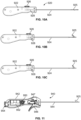
- the treatment system 940 includes a handle 942 and an elongate member 944 extending from the handle.
- a shaft or wire (not shown) configured within the elongate member 944 is attached to a treatment device 925 and alternatively or additionally, a rotatable trigger 946 is attached at a lower, distal portion of the handle 942.
- Configured within the handle 942 is a slider 947 that is attached to the shaft or wire and is associated and cooperates with the trigger 946.
- a constant force spring 950 is associated and cooperates with the slider 947 to retract cutting structure of the treatment device 925 when the trigger 946 is released.
- transillumination structure is configured within the handle 942 and includes a battery compartment 952 and an electrical switch 954 for turning on and off a light source (e.g. LED) configured at a distal end of the treatment system 940.
- the spring 950 retracts the shaft or wire associated with the treatment device 925, and positions the shaft or wire within a detent on the slider 947 to signal the user with a tactile feedback that the cutting structure of the treatment device 925 is exposed.
- the treatment system 940 can then be re-positioned and manipulated again to treat additional areas.
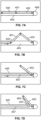
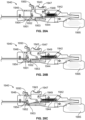
- a first link 1400 includes a blade 1401 and is rotatably attached at one end to a second link 1402.
- the opposite end of the first link 1400 slides with respect to a longitudinal shaft 1405 (shown as at least partially transparent).
- the shaft 1405 defines a housing for supporting and containing the linkage arrangement.
- a second end of the second link 1402 is rotationally affixed to a distal point on the shaft 1405.
- a drive shaft or push rod 1407 is rotatably or pivotably attached to the opposite end of the first link 1400 and the second link 1402 includes a generally triangular or pointed projection 1408 that is sized and shaped to shield the blade 1401 from contacting tissue when the assembly is placed in a hooking configuration.
- the blade 1401 is sheathed within the body of the longitudinal shaft 1405. It is noted that in the fully retracted configuration that the first and second links 1400, 1401 form an obtuse angle and the projection 1408 extends a relatively small distance from an opposite side of the longitudinal shaft.
- the projection 1408 contacts the push rod 1407 and the blade 1401 is again protected by the projection 1408 ( Fig. 12B ). It is in this configuration that the treatment device can be used to hook target septa and to test septa to determine if such septa is associated with the expression of cellulite on a patient's skin. Withdrawing the push rod 1407 from its fully advanced position and on the order of about 1, 778 mm (0.070 inches) in one embodiment (See Fig. 12C where the blade 1401 is shown transparent for illustrative purposes), the blade 1401 is exposed and presented for engaging and cutting, slicing or disrupting target septa.
- the treatment device also has a blunt, atraumatic tip 1406 that allows the treatment device to be advanced through the subcutaneous tissue with little trauma.
- blunt tip 1406 can house a light emitting diode, be a light emitting diode or house the end of a light fiber in order to facilitate transillumination through the skin for the user to use for guidance in knowing the location of the tip of the treatment device.
- the tip in any of the disclosed embodiments can be shaped so as to be characterized by or associated with a low introduction and advancement force through and within the patient's skin and anatomy, while also presenting a low likelihood of damaging tissue.
- the tip can assume bullet point or short dilator tip shapes, or can define a sharp profile or a trocar-type configuration for ease of advancement or tracking.
- the tip can be retractable, reconfigurable or otherwise define a sharpened structure only when the tip is presented with a pre-determined level of resistance.
- a spring loaded cover or shield is configured about the tip such that when presented with a defined resistance, the cover or shield is removed to expose a sharpened tip configured to facilitate advancement of the treatment device or reduce the force to cross patient anatomy.
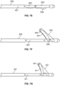
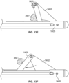
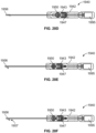
- the second link 1402 includes a blade 1401 that has a sharpened protrusion 1403, and the first link 1400 functions as a blocker to shield a main portion of the blade 1401 from contacting tissue when the treatment device is in the hooking configuration.
- the sharpened protrusion 1403 extends proximally from the pivot between the first link 1400 and second link 1402 so that as the treatment device is pulled proximally by the user, the pivot location, as the leading portion of the device during retraction, does not get snagged in tissue but rather slices through it so the user can hook and feel resistance of septa with the main portion of the first link 1400.
- the first and second links 1400, 1401 define an obtuse angle and when the push rod 1407 is advanced nearly completely ( Fig. 13B ), a majority of the blade 1401 is protected by the second link 1402.
- structure is presented in a hook-form both to encourage hook capture as well as provide a portion of unprotected blade 1403 near the connection between the first and second 1400, 1402 links.
- Completely advancing the push rod 1407 fully exposes the blade 1401 for cutting, slicing or disrupting target septa (See Figs. 13C-D; Fig. 13D showing the first blade as transparent for illustrative purposes) as the treatment device is retracted proximally by the user.
- treatment devices that include a hinge link arrangement 1400, 1402 or similar structure that transition from a hooked configuration ( Fig. 13E ) toward a stowed configuration ( Fig. 13F ) by pivoting relative to the longitudinal shaft 1405, benefit from the blocking link 1400 (or similar structure) moving to push septa 350 or other tissue away from the treatment device as the treatment device is being sheathed or stowed.
- This action requires no additional advancement of the treatment device within patient anatomy and ensures that septa 350 or other tissue do not become undesirably entrapped.
- the links 1400, 1402 dislodge any tissue that might have become captured within the longitudinal shaft 1405 and the links 1400, 1402 ultimately occupy such spaces within the longitudinal shaft 1405.
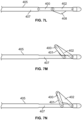
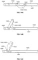
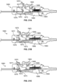
- Figs. 14A-F there is shown yet another approach to a treatment device.
- the first links 1420, 1422 each define a curved or yoke-shaped member with a unique profile designed to selectively shield the second link 1402, a first end 1424 of each rotatably or pivotably attached to a pusher 1407 and second ends 1426 rotatably or pivotably attached to the second link 1402.
- the parallel arranged first links 1420, 1422 provide additional strength for the hooking and cutting positions.
- a curved portion of the first links 1420, 1422 projects from an opposite side of the longitudinal shaft 1405 (shown at least partially transparent) from which the links extend when deployed for hooking or cutting, slicing or disrupting septa.
- the push rod 1407 is advanced so that the first links 1420, 1422 completely shield or block the blade 1401 (See Figs 14B and 14E ; one first link 1420 is shown as transparent for illustrative purposes in Fig. 14E ) from contacting tissue.
- Advancing the push rod 1405 completely operates to fully expose the blade 1401 (See Figs. 14C and 14F ) and thus present the blade 1401 for cutting, slicing or disrupting target tissue.
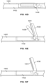
- a treatment device can alternatively or additionally include first and second push rods 1430, 1432, the first push rod 1430 configured to manipulate an articulating or pivoting first link 1434 and the second push rod 1432 configured to manipulate an articulating or pivoting second link 1436 that includes a blade 1401 surface.
- first and second push rods 1430, 1432 When the push rods 1430, 1432 are in a fully advanced position ( Figs. 15A and 15D ), the first 1434 and second 1436 links are generally parallel and stowed within the longitudinal shaft 1405 (shown at least partially transparent). Withdrawing the push rods 1430, 1432 operate to project the first 1434 and second 1436 links from the stowed position (See Figs. 15B , C, E, F).
- a welded pin or swaged tube 1450 can be used at the connection between first 1400 and second link or links 1402.
- mechanical joining such as a welded pin or swaged tube can form the connection between second link or links 1402 and a distal portion of the longitudinal shaft 1405.
- Such pivot points can in one or more embodiments be defined by about 0.635 mm (0.025 inch) diameter pins or tubes, for example, and can be used at one or more rotating or pivoting connections of a treatment system.
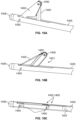
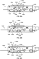
- a first link 1400 including a blade 1401 can be configured between a pair of second links 1402 (one link shown as transparent) rather than concealed by or cooperating with a single first link 1400.
- a treatment system lacks projecting structure when the links 1400, 1402 are fully retracted and housed within the longitudinal shaft 1405 ( Fig. 17A ).
- the first link 1400 acting as a blocking or blunt element can be spring loaded so that it shields the blade 1401 formed on the second link 1402 ( Fig. 17B ) until a critical force is achieved and then the blade 1401 is presented ( Fig. 17C ) for cutting, slicing or disrupting target septa.
- the blade 1401 can be configured to automatically be re-sheathed or an actuator such as a button can be provided to re-sheath the blade 1401.
- the blade 1401 is fully sheathed or contained within the longitudinal shaft 1405 during navigation, and deployed when necessary.
- the longitudinal shaft 1405 can be formed from a hypotube for example, with fewer cuts for ejecting and storing the links 1400, 1402.
- Such structure or related functionality can be incorporated into any of the disclosed embodiments to thus provide spring-loaded cutting to require a certain, controlled amount of force to expose the blade for cutting.
- This embodiment could also have blunt tip 1406.
- the blocking or hooking function is provided by a pair of curved or angled first links 1400.
- the curved or angled links 1400 project from an opposite side of the longitudinal shaft 1405 from the deployed or treatment side of the shaft 1405 ( Fig. 18A ).
- the blocking or shielding first links 1400 are spring loaded so that they reside on opposite sides and shield the blade 1401 ( Fig. 18B ) until a critical force is achieved and then the blade is exposed ( Fig. 18C ) for cutting, slicing or disrupting target septa.
- the blade 1401 can be configured to automatically be re-sheathed or an actuator such as a button can be provided to re-sheath the blade 1401, and there is two positions of the links, namely sheathed and deployed.
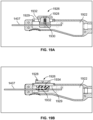
- a handle 1922 of a treatment device that includes a trigger or slider assembly 1926 that includes a depressible button 1928.
- the handle 1922 includes a track 1929 along which the button 1928 is registered.
- the button 1928 in one embodiment, is biased relative to the track 1929 by a helical spring 1930.
- the slider assembly 1926 is attached to a drive shaft or pusher 1407 that is connected to and facilitates manipulation of a treatment device (not shown).
- the button 1928 is depressible to release a locking or other engagement between the button 1928 and the track 1929 so that the slider assembly 1926 can be slid relative to the handle 1922.
- the button 1930 is biased by a leaf spring 1934.
- the button 1928 is configured to be separately actuatable and defines an independently depressible structure from the sliding structure of the slider assembly 1926 to thereby provide alternative discrete control of sliding and locking functions.
- a treatment system 1940 includes a handle assembly 1942 that includes a slider 1943 biased by a spring 1944, the slider 1943 is configured to be translated along a portion of a body 1946 of the handle assembly 1942.
- a button 1947 projects vertically from an upper surface of the slider 1943, the button 1947 being connected to or associated with a boss 1948 that rides within a slot formed in the slider 1942.
- the boss 1948 also slides along and is configured to be registered along a ramp 1949 or other engaging structure formed within the handle body 1946.
- rotatably attached to the slider 1943 is a lever 1950 that includes a curved slot 1951 that receives a boss 1952 projecting from a bracket 1953.
- Each of the slider 1943 and the bracket 1953 are attached to one or more longitudinally extending members 1954 that is/are associated with a treatment device 1956 attached at a terminal end portion thereof (See Figs. 20D-F ).
- Attached to the proximal end of the handle assembly 1942 is an optional light and energy source unit 1995, for example, a light emitting diode and battery.
- Extending distally through the handle assembly 1942 and longitudinal shaft of the treatment device 1956 to the distal portion of the longitudinal shaft is a light fiber (not shown) to transmit light from the light and energy source unit 1995 to the distal portion of the treatment device 1956 to provide transillumination through the skin for the user.
- a treatment device stowed position See Figs. 20A and D
- the slider 1943 In a treatment device stowed position (See Figs. 20A and D ), the slider 1943 is in its most proximal position and the spring 1944 is mostly compressed.
- the spring 1944 As the slider 1943 is translated forward ( Figs. 20B and E ), the spring 1944 is extended and the slider boss 1948 becomes temporarily and fixedly registered along the ramp 1949. Due to this action, the longitudinally extending member 1954 is advanced to manipulate the treatment device 1956. It is in this configuration that the treatment device 1956 is in a deployed but covered configuration intended for hooking or otherwise engaging target septa.
- the longitudinally extending member 1956 By subsequently depressing the rotatable lever 1950, through the interaction of the lever 1950 and the bracket 1953, the longitudinally extending member 1956 is advanced slightly further in a distal direction to uncover a treatment device sharpened link or blade 1957 (See Figs.
- the sharpened link or blade 1957 being configured for cutting, slicing or disrupting septa.
- a spring (not shown) is configured between the lever 1950 and bracket 1953 to bias the lever 1950 to return the treatment device 1956 to a locked and hook configuration.
- the slider button 1947 is depressed to release the engagement between the slider boss 1948 and the ramp 1949 to thereby permit the spring 1944 to return the slider 1943 to its most proximal position and to stow away the treatment device 1956 for further use or removal from the interventional site.
- the system 1940 would lack the lever 1950 and an additional spring (not shown) is configured to only allow advancement of the bracket 1953 when the treatment device 1956 is presented with a pre-determined resistance, at which time the blade 1957 is permitted to be exposed. In this way, the tool is more easy to use and the cutting step subsequent to hooking septa is less likely to be omitted.
- the treatment system 1960 includes a handle assembly 1962 that includes a slider 1963 biased by a spring 1964, the slider 1963 also being configured to be translated along a portion of a body 1966 of the handle assembly 1962.
- the slider 1963 is configured to rotate with respect to the body 1966 and the slider 1963 itself includes a boss 1968 that slides along and is configured to be registered along a ramp 1969 or other engaging structure formed within the handle body 1966.
- rotatably attached to the slider 1962 is a lever 1970 that includes a curved slot 1971 that receives a boss 1972 projecting from a bracket 1973.
- Each of the slider 1962 and the bracket 1973 are attached to one or more longitudinally extending members 1976 that is/are associated with a treatment device attached at a terminal end portion thereof (Not shown, but for example like the structures depicted in Figs. 20D-F ).
- a treatment device When a treatment device is in a stowed position (See Figs. 21A ), the slider 1962 is in its most proximal position and the spring 1964 is mostly compressed. As the slider 1962 is translated forward ( Fig. 21B ), the spring 1964 is extended and the slider boss 1968 becomes temporarily and fixedly registered along the ramp 1969, and the longitudinally extending member 1976 is advanced to manipulate the treatment device. It is in this configuration that the treatment device is in a deployed but covered configuration intended for hooking or otherwise engaging target septa. Thereafter, by depressing the rotatable lever 1970, through the interaction of the lever 1970 and the bracket 1973, the longitudinally extending member 1976 is advanced slightly further in a distal direction to uncover a treatment device sharpened link or blade (See Fig. 21C ).
- the treatment device is configured to cut, slice or disrupt target septa.
- a spring (not shown) is configured between the lever 1970 and bracket 1973 to bias the lever 1970 to return the treatment device to a locked and hook configuration.
- the slider 1962 is depressed and rotated to release the engagement between the slider boss 1968 and the ramp 1969 to thereby permit the spring 1964 to return the slider 1962 to its most proximal position and to stow away the treatment device.
- the treatment device 1980 can additionally or alternatively include a handle assembly 1982 that includes a slider 1984 configured to slide along a body of the handle assembly 1982.
- a handle assembly 1982 that includes a slider 1984 configured to slide along a body of the handle assembly 1982.
- the treatment device (not shown) is in a stowed position.
- the slider 1984 is attached to a pair of rotatable, angled members 1986, 1987, the ends of each of which are rotatably attached to the the handle body and to the slider 1984, respectively.
- the forwardly positioned rotatable member 1986 further includes an extension 1988 that is rotatably attached to a rotatable bracket 1989 that is in turn rotatably attached to a longitudinally extending member 1990 that has a treatment device (not shown) attached to a distal end portion thereof.
- a button 1992 projects vertically from the slider 1984 and the button 1992 is associated with a boss 1993 that is configured to be registered along a portion of the body of the handle assembly 1982 (See Fig. 22B ). When so positioned with the slider 1984 advanced along the handle body and the boss 1993 registered within a recess 1994 formed in the handle body, the treatment device is deployed but covered at least partially to present structure for hooking or engaging target septa.
- the boss 1993 of the slider 1984 can be disengaged from the recess 1994 to thereby permit the slider 1992 to be advanced further distally.
- the longitudinally extending member 1990 can be advanced further to expose a cutting portion of a treatment device for cutting, slicing or engaging tissue and accomplishing desired interventional treatments.
- the slider 1992 can then be returned to either of the stowed or deployed but covered positions as desired for further interventional steps. Accordingly, this approach provides a mechanism that scales up small movements of the handle assembly so that the configuration of the treatment device (e.g., contained, hook or cut positions) is made more obvious to the user.
- a "ball point pen” type of mechanism can be used in the handle assembly such that after the hook and/or sharpened edge have torn or cut through septa, the linkage automatically restows upon a sudden reduction in force on the linkage as it tears or cuts through the septa.
- a coil is deployed from the distal portion of the treatment device and rotated to wind the septa into the coil to re-create the targeted cellulite on the skin surface, then the coil is pulled by the user to disrupt or cut the septa or a cutter is used to sever the septa.
- the disclosed approaches are configured to provide an effective and focused approach to treating, minimizing and preventing cellulite.
- the disclosed approaches can also be used to repair and reduce the appearance of cellulite in a targeted manner.
- the disclosed proactive treatment modalities are easy and effective to use.
- Some of the specific aspects of the present disclosure include one or more of focal treatment of just the septa responsible for causing dimples or depressions in the skin; minimizing bruising; accessing all treatment targets from limited, cosmetically acceptable entries; capture and retention of septa while separating the septa; intra-operative confirmation of treated target; needle-diameter sized tools for small openings; and transillumination identification of tool tip location.
Landscapes
- Health & Medical Sciences (AREA)
- Life Sciences & Earth Sciences (AREA)
- Surgery (AREA)
- General Health & Medical Sciences (AREA)
- Public Health (AREA)
- Veterinary Medicine (AREA)
- Nuclear Medicine, Radiotherapy & Molecular Imaging (AREA)
- Animal Behavior & Ethology (AREA)
- Molecular Biology (AREA)
- Engineering & Computer Science (AREA)
- Biomedical Technology (AREA)
- Heart & Thoracic Surgery (AREA)
- Medical Informatics (AREA)
- Orthopedic Medicine & Surgery (AREA)
- Biophysics (AREA)
- Radiology & Medical Imaging (AREA)
- Physics & Mathematics (AREA)
- Pathology (AREA)
- Optics & Photonics (AREA)
- Surgical Instruments (AREA)
- Medicines That Contain Protein Lipid Enzymes And Other Medicines (AREA)
Claims (11)
- Eine Cellulite-Behandlungsvorrichtung zur Behandlung von Cellulite-Ausprägungen auf der Haut eines Patienten in Verbindung mit einer Septenbehandlungsstelle, aufweisend:einen Griff (942);einem Schaft (405), der sich in Längsrichtung vom Griff aus erstreckt, wobei der Schaft so bemessen und geformt ist, dass er in das Gewebe eingeführt und zwischen Gewebeschichten zur Septenbehandlungsstelle vorgeschoben werden kann; undeine Septeneingriffs- und -schneidanordnung (401, 402) an einem distalen Abschnitt des Schafts, wobei die Septeneingriffs- und Schneidanordnung eine Klinge (401) enthält;und aufweisend eine Aktuator (407) am Griff, um die Septeneingriffs- und Schneideanordnung zu betätigen, wobei der Aktuator die Septeneingriffs- und Schneideanordnung positioniert in mindestens einer verdeckten Position, einer Septenspannposition, in der die Septeneingriffsanordnung entfaltet und konfiguriert ist, dass sie Septen spannt und die Klinge abgedeckt ist, und einer Septendurchtrennungsposition, in der die Septeneingriffsanordnung entfaltet ist und die Klinge freiliegt, um Septen zu durchtrennen, wobei die Septeneingriffs- und -schneidanordnung so konfiguriert ist, dass sie seitlich in Bezug auf den Schaft entfaltet wird.
- Die Cellulite-Behandlungsvorrichtung nach Anspruch 1 weiterhin aufweisend eine Durchleuchtungsstruktur (352, 354).
- Die Vorrichtung nach Anspruch 2, wobei die Durchleuchtungsstruktur in einer entlang eines distalen Abschnitts des Schafts angeordneten Leuchte verkörpert ist.
- Die Vorrichtung nach Anspruch 3, wobei es sich bei der Leuchte um eine oder mehrere LED oder einen Lichtleiter handelt.
- Die Vorrichtung nach Anspruch 1, wobei, in der Spannposition der Septen, die Septeneingriffs- und -schneidanordnung eine V-förmige Struktur mit seitlicher Öffnung bildet.
- Die Vorrichtung nach Anspruch 1, wobei die Septeneingriffs- und - schneidanordnung seitlich vorstehende Verbindungselemente umfasst.
- Die Vorrichtung nach Anspruch 1, in der Spannposition der Septen, die Septeneingriffs- und -schneidanordnung einen seitlich öffnenden Haken definiert.
- Die Vorrichtung nach Anspruch 1, wobei, in der Spannposition der Septen, die Septeneingriffs- und -schneidanordnung einen schrägen Haken aufweist.
- Die Vorrichtung nach Anspruch 1, wobei die Septeneingriffs- und - schneidanordnung eine rotierende Struktur Klinge aufweist.
- Die Vorrichtung nach Anspruch 1, wobei die Klinge ein harmonisches Skalpell enthält.
- Die Vorrichtung nach Anspruch 1, wobei die Septeneingriffs- und - schneidanordnung eine selektive Kauterstruktur oder eine Energieübertragungsstruktur aufweist.
Applications Claiming Priority (6)
| Application Number | Priority Date | Filing Date | Title |
|---|---|---|---|
| US201862702314P | 2018-07-23 | 2018-07-23 | |
| US201862736016P | 2018-09-25 | 2018-09-25 | |
| US201962798515P | 2019-01-30 | 2019-01-30 | |
| US201962802368P | 2019-02-07 | 2019-02-07 | |
| US201962825447P | 2019-03-28 | 2019-03-28 | |
| PCT/US2019/042871 WO2020023412A1 (en) | 2018-07-23 | 2019-07-22 | Cellulite treatment system and methods |
Related Child Applications (1)
| Application Number | Title | Priority Date | Filing Date |
|---|---|---|---|
| EP24183504.0 Division-Into | 2024-06-20 |
Publications (3)
| Publication Number | Publication Date |
|---|---|
| EP3826558A1 EP3826558A1 (de) | 2021-06-02 |
| EP3826558A4 EP3826558A4 (de) | 2022-04-20 |
| EP3826558B1 true EP3826558B1 (de) | 2024-09-04 |
Family
ID=69181894
Family Applications (1)
| Application Number | Title | Priority Date | Filing Date |
|---|---|---|---|
| EP19841959.0A Active EP3826558B1 (de) | 2018-07-23 | 2019-07-22 | Cellulitebehandlungssystem |
Country Status (9)
| Country | Link |
|---|---|
| US (4) | US11974767B2 (de) |
| EP (1) | EP3826558B1 (de) |
| JP (2) | JP7458653B2 (de) |
| CN (2) | CN112752549B (de) |
| BR (1) | BR112021001186A8 (de) |
| CA (1) | CA3107347A1 (de) |
| ES (1) | ES2989422T3 (de) |
| MX (1) | MX2021000902A (de) |
| WO (1) | WO2020023412A1 (de) |
Families Citing this family (8)
| Publication number | Priority date | Publication date | Assignee | Title |
|---|---|---|---|---|
| US11980388B2 (en) | 2018-07-23 | 2024-05-14 | Revelle Aesthetics, Inc. | Cellulite treatment apparatus |
| JP7458653B2 (ja) | 2018-07-23 | 2024-04-01 | リベル・エスセティクス・インコーポレイテッド | セルライト治療システムおよび方法 |
| MX2022002743A (es) | 2019-09-06 | 2022-06-29 | Revelle Aesthetics Inc | Sistema y métodos de tratamiento de la celulitis. |
| US12137927B2 (en) * | 2021-01-25 | 2024-11-12 | Matthew Donavon Forrester | Cutting grasper for valve leaflet laceration |
| WO2023154474A1 (en) * | 2022-02-11 | 2023-08-17 | Revelle Aesthetics, Inc. | Aesthetic treatment systems and methods |
| AU2024257424A1 (en) * | 2023-04-20 | 2025-11-27 | Revelle Aesthetics, Inc. | Aesthetic treatment systems and methods |
| WO2025193721A1 (en) | 2024-03-11 | 2025-09-18 | Revelle Aesthetics, Inc. | Light assembly and methods for use with a needle or cannula |
| WO2026019948A1 (en) | 2024-07-16 | 2026-01-22 | Revelle Aesthetics, Inc. | Aesthetic energy treatment systems and methods |
Family Cites Families (107)
| Publication number | Priority date | Publication date | Assignee | Title |
|---|---|---|---|---|
| US4444185A (en) | 1981-08-19 | 1984-04-24 | Shugar Martin A | Fiberoptic tracheotomy method |
| JPH0249012A (ja) | 1989-07-14 | 1990-02-19 | Toray Ind Inc | 新規グラフト共重合体の製造方法 |
| EP0487645B1 (de) | 1989-08-16 | 1995-12-13 | Raychem Corporation | Anordnung zum greifen oder schneiden eines gegenstandes |
| US5478347A (en) | 1990-10-05 | 1995-12-26 | United States Surgical Corporation | Endoscopic surgical instrument having curved blades |
| US5113476A (en) | 1990-11-08 | 1992-05-12 | Mitsubishi Rayon Company Ltd. | Light attenuator and process for fabrication thereof |
| WO1992008415A1 (en) | 1990-11-09 | 1992-05-29 | Arthrotek, Inc. | Surgical cutting instrument |
| US6540764B1 (en) | 1992-06-02 | 2003-04-01 | General Surgical Innovations, Inc. | Apparatus and method for dissecting tissue layers |
| GB9225321D0 (en) * | 1992-12-03 | 1993-01-27 | Univ Bristol | Evisceration |
| JP3020409B2 (ja) | 1994-05-17 | 2000-03-15 | 株式会社精工技研 | 拡大された入射端面をもつ光結合装置 |
| US6241753B1 (en) | 1995-05-05 | 2001-06-05 | Thermage, Inc. | Method for scar collagen formation and contraction |
| US5728112A (en) | 1995-09-22 | 1998-03-17 | Yoon; Inbae | Combined tissue clamping and suturing instrument |
| JP3252088B2 (ja) | 1996-04-26 | 2002-01-28 | 長谷川刃物株式会社 | 鋏 |
| US6165188A (en) | 1996-12-02 | 2000-12-26 | Angiotrax, Inc. | Apparatus for percutaneously performing myocardial revascularization having controlled cutting depth and methods of use |
| US7204832B2 (en) * | 1996-12-02 | 2007-04-17 | Pálomar Medical Technologies, Inc. | Cooling system for a photo cosmetic device |
| JPH11218652A (ja) | 1998-02-03 | 1999-08-10 | Seiko Giken Kk | 光ファイバの光源組立およびその製造方法 |
| US6447527B1 (en) * | 1998-04-23 | 2002-09-10 | Ronald J. Thompson | Apparatus and methods for the penetration of tissue |
| GB2350080A (en) | 1999-04-10 | 2000-11-22 | Liou Yaw Jang | Suture removal instrument |
| WO2001049194A2 (en) * | 1999-12-30 | 2001-07-12 | Pearl Technology Holdings, Llc | Face-lifting device |
| US7992573B2 (en) | 2001-06-19 | 2011-08-09 | The Trustees Of The University Of Pennsylvania | Optically guided system for precise placement of a medical catheter in a patient |
| US20040260210A1 (en) | 2003-06-23 | 2004-12-23 | Engii (2001) Ltd. | System and method for face and body treatment |
| CN2504047Y (zh) | 2001-10-24 | 2002-08-07 | 庄福财 | 切粒机的旋转刀具 |
| US6916328B2 (en) * | 2001-11-15 | 2005-07-12 | Expanding Concepts, L.L.C | Percutaneous cellulite removal system |
| EP1627662B1 (de) | 2004-06-10 | 2011-03-02 | Candela Corporation | Apparat für vakuumunterstützte dermatologische Phototherapien |
| US20030130628A1 (en) | 2002-01-08 | 2003-07-10 | Duffy David M. | Method and apparatus for the treatment of scar tissue and wrinkles |
| US8840608B2 (en) | 2002-03-15 | 2014-09-23 | The General Hospital Corporation | Methods and devices for selective disruption of fatty tissue by controlled cooling |
| US20030187457A1 (en) * | 2002-04-02 | 2003-10-02 | Weber John A. | Apparatus and method for removing an object from a body |
| US7442192B2 (en) | 2002-07-14 | 2008-10-28 | Knowlton Edward W | Method and apparatus for surgical dissection |
| US20040206365A1 (en) * | 2003-03-31 | 2004-10-21 | Knowlton Edward Wells | Method for treatment of tissue |
| US20040204734A1 (en) * | 2003-04-11 | 2004-10-14 | Wagner Darrell Orvin | Tunneling tool with subcutaneous transdermal illumination |
| US7223275B2 (en) | 2003-05-27 | 2007-05-29 | Yichieh Shiuey | System for cutting the cornea of an eye |
| WO2006034077A1 (en) | 2004-09-16 | 2006-03-30 | Juva Medical, Inc. | Tissue augmentation device |
| US8133180B2 (en) * | 2004-10-06 | 2012-03-13 | Guided Therapy Systems, L.L.C. | Method and system for treating cellulite |
| US7771199B2 (en) | 2004-10-15 | 2010-08-10 | Ace Surgical Supply Co, Inc. | Bone cutting osteotome tool and method for preparing a surgical sinus-lift osteotomy |
| US20060241663A1 (en) | 2005-04-21 | 2006-10-26 | Zimmer Spine, Inc. | Surgical cutter |
| US20060241673A1 (en) | 2005-04-21 | 2006-10-26 | Zadini Filiberto P | Subcision device |
| US20070005091A1 (en) | 2005-04-21 | 2007-01-04 | Zadini Filiberto P | Infra-epidermic subcision device for blunt dissection of sub-epidermic tissues |
| ATE526890T1 (de) | 2005-04-29 | 2011-10-15 | Bovie Medical Corp | Zange zur durchführung einer endoskopischen oder arthroskopischen operation |
| US7217265B2 (en) | 2005-05-18 | 2007-05-15 | Cooltouch Incorporated | Treatment of cellulite with mid-infrared radiation |
| US9486274B2 (en) | 2005-09-07 | 2016-11-08 | Ulthera, Inc. | Dissection handpiece and method for reducing the appearance of cellulite |
| US8518069B2 (en) | 2005-09-07 | 2013-08-27 | Cabochon Aesthetics, Inc. | Dissection handpiece and method for reducing the appearance of cellulite |
| US9358033B2 (en) | 2005-09-07 | 2016-06-07 | Ulthera, Inc. | Fluid-jet dissection system and method for reducing the appearance of cellulite |
| US7967763B2 (en) | 2005-09-07 | 2011-06-28 | Cabochon Aesthetics, Inc. | Method for treating subcutaneous tissues |
| EP2796168B1 (de) | 2005-09-28 | 2017-09-06 | Candela Corporation | Behandlung von Cellulitis |
| JP5063358B2 (ja) | 2005-10-31 | 2012-10-31 | テルモ株式会社 | 穿刺器具、投与器具及び穿刺方法 |
| US20080200863A1 (en) | 2005-12-02 | 2008-08-21 | Cabochon Aesthetics, Inc. | Devices and methods for selectively lysing cells |
| US7885793B2 (en) | 2007-05-22 | 2011-02-08 | International Business Machines Corporation | Method and system for developing a conceptual model to facilitate generating a business-aligned information technology solution |
| US8048089B2 (en) | 2005-12-30 | 2011-11-01 | Edge Systems Corporation | Apparatus and methods for treating the skin |
| US8308740B2 (en) | 2006-06-05 | 2012-11-13 | Kristin Ann Tolley | Needle stabilizer |
| US20080051627A1 (en) | 2006-08-28 | 2008-02-28 | Board Of Regents, The University Of Texas System | Endoscopic insertion of balloon system and method |
| US20080058603A1 (en) | 2006-09-01 | 2008-03-06 | Edelstein Peter S | Method and Apparatus for Assisting in the Introduction of Surgical Implements into a Body |
| US20080109023A1 (en) | 2006-11-03 | 2008-05-08 | Greer Steven E | Method and apparatus for altering the appearance of a patient's skin |
| JP5249204B2 (ja) | 2007-04-27 | 2013-07-31 | テルモ株式会社 | 穿刺器具 |
| US8439940B2 (en) * | 2010-12-22 | 2013-05-14 | Cabochon Aesthetics, Inc. | Dissection handpiece with aspiration means for reducing the appearance of cellulite |
| EP2209424A1 (de) | 2007-10-09 | 2010-07-28 | Cabochon Aesthetics, Inc. | Ultraschallgerät mit behandlungslinse |
| US7671423B2 (en) | 2008-01-10 | 2010-03-02 | International Business Machines Corporation | Resistor ballasted transistors |
| WO2009108933A2 (en) | 2008-02-28 | 2009-09-03 | Palomar Medical Technologies, Inc. | Systems and methods for treatment of soft tissue |
| US8652123B2 (en) | 2008-09-02 | 2014-02-18 | Geoffrey C. GURTNER | Methods and devices for improving the appearance of tissue |
| CN107898498B (zh) | 2008-10-21 | 2021-06-11 | 微立方有限责任公司 | 将能量应用于身体组织的方法及装置 |
| US20100106063A1 (en) | 2008-10-29 | 2010-04-29 | Cabochon Aesthetics, Inc. | Ultrasound Enhancing Target for Treating Subcutaneous Tissue |
| JP2012519554A (ja) | 2009-03-05 | 2012-08-30 | サイノシュア・インコーポレーテッド | 熱的外科手術安全装置および熱的外科手術方法 |
| US8167280B2 (en) | 2009-03-23 | 2012-05-01 | Cabochon Aesthetics, Inc. | Bubble generator having disposable bubble cartridges |
| US20100256596A1 (en) | 2009-04-07 | 2010-10-07 | Cabochon Aesthetics, Inc. | Fiber growth promoting implants for reducing the appearance of cellulite |
| US10080482B2 (en) * | 2009-06-30 | 2018-09-25 | Intuitive Surgical Operations, Inc. | Compliant surgical device |
| US20120116271A1 (en) * | 2009-07-23 | 2012-05-10 | Palomar Medical Technologies, Inc. | Cellulite treatment |
| US9919168B2 (en) | 2009-07-23 | 2018-03-20 | Palomar Medical Technologies, Inc. | Method for improvement of cellulite appearance |
| US9358064B2 (en) | 2009-08-07 | 2016-06-07 | Ulthera, Inc. | Handpiece and methods for performing subcutaneous surgery |
| US8840631B2 (en) | 2009-10-29 | 2014-09-23 | Cook Medical Technologies Llc | Compartment syndrome treatment method and surgical instrument for same |
| CN201617909U (zh) | 2010-03-22 | 2010-11-03 | 单良 | 肋骨剪 |
| US20110295297A1 (en) | 2010-05-26 | 2011-12-01 | Medicinelodge, Inc. Dba Imds Co-Innovation | Dice cutting surgical instrument |
| WO2012006143A2 (en) * | 2010-06-29 | 2012-01-12 | Lipovera, Llc | Disposable surgical instruments |
| CN202154724U (zh) | 2011-06-20 | 2012-03-07 | 宋瑞鹏 | 一种肠道手术剪 |
| US8945177B2 (en) * | 2011-09-13 | 2015-02-03 | Abbott Cardiovascular Systems Inc. | Gripper pusher mechanism for tissue apposition systems |
| KR102043476B1 (ko) * | 2011-10-17 | 2019-11-12 | 사운드 써지칼 테크놀로지 엘엘씨 | 셀룰라이트를 처리하기 위한 초음파 프로브 |
| ES2741476T3 (es) | 2011-10-21 | 2020-02-11 | Endo Global Ventures | Método para el tratamiento o reducción de PFE |
| US20130197515A1 (en) | 2012-01-31 | 2013-08-01 | Boston Scientific Scimed, Inc. | Endoscopic instrument having a cutting tool |
| CN202821527U (zh) | 2012-10-24 | 2013-03-27 | 宋佰峰 | 普外科用防滑脱手术剪刀 |
| US20140276693A1 (en) | 2013-03-15 | 2014-09-18 | Palomar Medical Technologies, Llc | Treatment of tissue |
| US10117892B2 (en) * | 2013-08-29 | 2018-11-06 | Allergan, Inc. | Devices and methods for reducing the appearance of cellulite |
| CN104644244A (zh) | 2013-11-25 | 2015-05-27 | 成都卓青科技有限公司 | 一种外科手术剪 |
| WO2015106118A1 (en) * | 2014-01-09 | 2015-07-16 | Sonitec Llc | Systems and methods using ultrasound for treatment |
| WO2015117001A1 (en) * | 2014-01-31 | 2015-08-06 | Zeltiq Aesthetics, Inc. | Compositions, treatment systems and methods for improved cooling of lipid-rich tissue |
| CN108186111B (zh) | 2014-08-20 | 2021-03-26 | 捷锐士阿希迈公司(以奥林巴斯美国外科技术名义) | 多模式复合电外科装置 |
| WO2016040820A1 (en) | 2014-09-12 | 2016-03-17 | Acclarent, Inc. | Uncinate process support for ethmoid infundibulum illumination |
| CN204191319U (zh) | 2014-10-28 | 2015-03-11 | 吉木萨尔县鑫绿源农业科技开发有限公司 | 一种用于玉米育种过程中去雄装置 |
| CN204500879U (zh) | 2015-02-13 | 2015-07-29 | 安徽理工大学 | 一种手术剪 |
| EP3288477A4 (de) | 2015-04-29 | 2018-12-19 | Cirrus Technologies Ltd. | Vorrichtung zur medizinischen ablation und verfahren zur verwendung |
| CA2985811A1 (en) | 2015-05-12 | 2016-11-17 | Soliton, Inc. | Methods of treating cellulite and subcutaneous adipose tissue |
| US9974519B1 (en) | 2015-07-01 | 2018-05-22 | Btl Holdings Limited | Aesthetic method of biologoical structure treatment by magnetic field |
| US10549110B1 (en) | 2015-07-01 | 2020-02-04 | Btl Medical Technologies S.R.O. | Aesthetic method of biological structure treatment by magnetic field |
| US11291466B2 (en) | 2015-08-10 | 2022-04-05 | Indiana University Research And Technology Corporation | Device and method for scar subcision |
| US10918412B2 (en) | 2015-12-18 | 2021-02-16 | Boston Scientific Scimed, Inc. | Surgical guidance devices, methods, and systems |
| WO2017120027A1 (en) | 2016-01-07 | 2017-07-13 | Intuitive Surgical Operations, Inc. | Telescoping cannula arm |
| AU2017222503A1 (en) * | 2016-02-25 | 2018-06-21 | Lalu JOSEPH | Improved reusable universal tissue morcellator system |
| US10603101B2 (en) | 2016-03-26 | 2020-03-31 | Paul Joseph Weber | Apparatus, systems and methods for minimally invasive dissection of tissues |
| US11253285B2 (en) | 2016-04-04 | 2022-02-22 | University Of Utah Research Foundation | Subcutaneous cutting device |
| AU2017261196B2 (en) | 2016-05-02 | 2022-03-03 | Stryker Corporation | Nasal valve implants and methods of implanting the same |
| CN112835157B (zh) | 2016-06-29 | 2022-07-12 | 安达满纳米奇精密宝石有限公司 | 光插座及光收发器 |
| WO2018136514A1 (en) | 2017-01-17 | 2018-07-26 | Soliton, Inc. | Rapid pulse electrohydraulic (eh) shockwave generator apparatus with improved acoustic wavefronts |
| US10773031B2 (en) | 2017-08-09 | 2020-09-15 | WLB Interventional, LLC | Needle for subcision procedures |
| WO2019060924A2 (en) | 2017-09-25 | 2019-03-28 | Weber, Michael | APPARATUS AND SYSTEMS FOR MINIMALLY INVASIVE DISSECTION OF FABRICS |
| WO2019164836A1 (en) | 2018-02-20 | 2019-08-29 | Ulthera, Inc. | Systems and methods for combined cosmetic treatment of cellulite with ultrasound |
| MX2021000901A (es) | 2018-07-23 | 2021-06-18 | Revelle Aesthetics Inc | Sistema y metodos de tratamiento de celulitis. |
| US20230255678A1 (en) | 2018-07-23 | 2023-08-17 | Revelle Aesthetics, Inc. | Aesthetic treatment systems and methods |
| JP7458653B2 (ja) | 2018-07-23 | 2024-04-01 | リベル・エスセティクス・インコーポレイテッド | セルライト治療システムおよび方法 |
| MX2022002743A (es) | 2019-09-06 | 2022-06-29 | Revelle Aesthetics Inc | Sistema y métodos de tratamiento de la celulitis. |
| WO2021150478A1 (en) | 2020-01-21 | 2021-07-29 | Nc8, Inc. | Systems for improving the appearance of tissue |
| WO2021150479A1 (en) | 2020-01-21 | 2021-07-29 | Nc8, Inc. | Systems for treating tissue |
-
2019
- 2019-07-22 JP JP2021527003A patent/JP7458653B2/ja active Active
- 2019-07-22 MX MX2021000902A patent/MX2021000902A/es unknown
- 2019-07-22 BR BR112021001186A patent/BR112021001186A8/pt active IP Right Grant
- 2019-07-22 ES ES19841959T patent/ES2989422T3/es active Active
- 2019-07-22 WO PCT/US2019/042871 patent/WO2020023412A1/en not_active Ceased
- 2019-07-22 CA CA3107347A patent/CA3107347A1/en active Pending
- 2019-07-22 CN CN201980062511.7A patent/CN112752549B/zh active Active
- 2019-07-22 EP EP19841959.0A patent/EP3826558B1/de active Active
- 2019-07-22 CN CN202511253734.5A patent/CN121337429A/zh active Pending
-
2021
- 2021-01-21 US US17/154,232 patent/US11974767B2/en active Active
- 2021-02-17 US US17/177,271 patent/US11013527B1/en active Active
-
2023
- 2023-08-14 US US18/233,406 patent/US12023063B2/en active Active
- 2023-08-24 US US18/237,450 patent/US12527594B2/en active Active
-
2024
- 2024-03-12 JP JP2024037746A patent/JP2024088643A/ja active Pending
Also Published As
| Publication number | Publication date |
|---|---|
| BR112021001186A8 (pt) | 2023-01-10 |
| CN121337429A (zh) | 2026-01-16 |
| ES2989422T3 (es) | 2024-11-26 |
| JP7458653B2 (ja) | 2024-04-01 |
| BR112021001186A2 (pt) | 2021-04-27 |
| US20230380854A1 (en) | 2023-11-30 |
| EP3826558A4 (de) | 2022-04-20 |
| JP2024088643A (ja) | 2024-07-02 |
| CN112752549A (zh) | 2021-05-04 |
| EP3826558A1 (de) | 2021-06-02 |
| MX2021000902A (es) | 2021-08-24 |
| US20230389951A1 (en) | 2023-12-07 |
| US11013527B1 (en) | 2021-05-25 |
| WO2020023412A1 (en) | 2020-01-30 |
| CN112752549B (zh) | 2025-09-19 |
| US12527594B2 (en) | 2026-01-20 |
| US11974767B2 (en) | 2024-05-07 |
| US20210137551A1 (en) | 2021-05-13 |
| JP2022502213A (ja) | 2022-01-11 |
| CA3107347A1 (en) | 2020-01-30 |
| US12023063B2 (en) | 2024-07-02 |
Similar Documents
| Publication | Publication Date | Title |
|---|---|---|
| US11013527B1 (en) | Cellulite treatment system and methods | |
| US12527597B2 (en) | Cellulite treatment system and methods | |
| US20230255678A1 (en) | Aesthetic treatment systems and methods | |
| WO1995014436A1 (en) | A retrograde high frequency tissue splitter | |
| US11980388B2 (en) | Cellulite treatment apparatus | |
| US20220347496A1 (en) | Systems for treating tissue | |
| US20220354565A1 (en) | Systems for improving the appearance of tissue | |
| JP2012510872A (ja) | 材料切除術のためのフード法及び装置 | |
| US20240390023A1 (en) | Aesthetic treatment systems and methods | |
| AU2024257424A1 (en) | Aesthetic treatment systems and methods | |
| WO2025199533A1 (en) | Aesthetic treatment systems | |
| WO2026019948A1 (en) | Aesthetic energy treatment systems and methods | |
| WO1993004635A1 (en) | Fascia cutter with cauterizing capability |
Legal Events
| Date | Code | Title | Description |
|---|---|---|---|
| STAA | Information on the status of an ep patent application or granted ep patent |
Free format text: STATUS: THE INTERNATIONAL PUBLICATION HAS BEEN MADE |
|
| PUAI | Public reference made under article 153(3) epc to a published international application that has entered the european phase |
Free format text: ORIGINAL CODE: 0009012 |
|
| STAA | Information on the status of an ep patent application or granted ep patent |
Free format text: STATUS: REQUEST FOR EXAMINATION WAS MADE |
|
| 17P | Request for examination filed |
Effective date: 20210121 |
|
| AK | Designated contracting states |
Kind code of ref document: A1 Designated state(s): AL AT BE BG CH CY CZ DE DK EE ES FI FR GB GR HR HU IE IS IT LI LT LU LV MC MK MT NL NO PL PT RO RS SE SI SK SM TR |
|
| DAV | Request for validation of the european patent (deleted) | ||
| DAX | Request for extension of the european patent (deleted) | ||
| RAP3 | Party data changed (applicant data changed or rights of an application transferred) |
Owner name: REVELLE AESTHETICS, INC. |
|
| A4 | Supplementary search report drawn up and despatched |
Effective date: 20220323 |
|
| RIC1 | Information provided on ipc code assigned before grant |
Ipc: A61B 17/3207 20060101ALN20220318BHEP Ipc: A61B 90/00 20160101ALN20220318BHEP Ipc: A61B 17/00 20060101ALN20220318BHEP Ipc: A61B 17/3205 20060101ALI20220318BHEP Ipc: A61B 17/3201 20060101ALI20220318BHEP Ipc: A61B 17/32 20060101AFI20220318BHEP |
|
| P01 | Opt-out of the competence of the unified patent court (upc) registered |
Effective date: 20230331 |
|
| GRAP | Despatch of communication of intention to grant a patent |
Free format text: ORIGINAL CODE: EPIDOSNIGR1 |
|
| STAA | Information on the status of an ep patent application or granted ep patent |
Free format text: STATUS: GRANT OF PATENT IS INTENDED |
|
| RIC1 | Information provided on ipc code assigned before grant |
Ipc: A61B 17/3207 20060101ALN20240201BHEP Ipc: A61B 90/00 20160101ALN20240201BHEP Ipc: A61B 17/00 20060101ALN20240201BHEP Ipc: A61B 17/3205 20060101ALI20240201BHEP Ipc: A61B 17/3201 20060101ALI20240201BHEP Ipc: A61B 17/32 20060101AFI20240201BHEP |
|
| INTG | Intention to grant announced |
Effective date: 20240229 |
|
| GRAS | Grant fee paid |
Free format text: ORIGINAL CODE: EPIDOSNIGR3 |
|
| GRAA | (expected) grant |
Free format text: ORIGINAL CODE: 0009210 |
|
| STAA | Information on the status of an ep patent application or granted ep patent |
Free format text: STATUS: THE PATENT HAS BEEN GRANTED |
|
| AK | Designated contracting states |
Kind code of ref document: B1 Designated state(s): AL AT BE BG CH CY CZ DE DK EE ES FI FR GB GR HR HU IE IS IT LI LT LU LV MC MK MT NL NO PL PT RO RS SE SI SK SM TR |
|
| REG | Reference to a national code |
Ref country code: GB Ref legal event code: FG4D |
|
| REG | Reference to a national code |
Ref country code: CH Ref legal event code: EP |
|
| REG | Reference to a national code |
Ref country code: IE Ref legal event code: FG4D |
|
| REG | Reference to a national code |
Ref country code: DE Ref legal event code: R096 Ref document number: 602019058445 Country of ref document: DE |
|
| REG | Reference to a national code |
Ref country code: ES Ref legal event code: FG2A Ref document number: 2989422 Country of ref document: ES Kind code of ref document: T3 Effective date: 20241126 |
|
| REG | Reference to a national code |
Ref country code: LT Ref legal event code: MG9D |
|
| REG | Reference to a national code |
Ref country code: NL Ref legal event code: MP Effective date: 20240904 |
|
| PG25 | Lapsed in a contracting state [announced via postgrant information from national office to epo] |
Ref country code: NO Free format text: LAPSE BECAUSE OF FAILURE TO SUBMIT A TRANSLATION OF THE DESCRIPTION OR TO PAY THE FEE WITHIN THE PRESCRIBED TIME-LIMIT Effective date: 20241204 |
|
| PG25 | Lapsed in a contracting state [announced via postgrant information from national office to epo] |
Ref country code: FI Free format text: LAPSE BECAUSE OF FAILURE TO SUBMIT A TRANSLATION OF THE DESCRIPTION OR TO PAY THE FEE WITHIN THE PRESCRIBED TIME-LIMIT Effective date: 20240904 Ref country code: GR Free format text: LAPSE BECAUSE OF FAILURE TO SUBMIT A TRANSLATION OF THE DESCRIPTION OR TO PAY THE FEE WITHIN THE PRESCRIBED TIME-LIMIT Effective date: 20241205 Ref country code: PL Free format text: LAPSE BECAUSE OF FAILURE TO SUBMIT A TRANSLATION OF THE DESCRIPTION OR TO PAY THE FEE WITHIN THE PRESCRIBED TIME-LIMIT Effective date: 20240904 |
|
| PG25 | Lapsed in a contracting state [announced via postgrant information from national office to epo] |
Ref country code: BG Free format text: LAPSE BECAUSE OF FAILURE TO SUBMIT A TRANSLATION OF THE DESCRIPTION OR TO PAY THE FEE WITHIN THE PRESCRIBED TIME-LIMIT Effective date: 20240904 |
|
| PG25 | Lapsed in a contracting state [announced via postgrant information from national office to epo] |
Ref country code: LV Free format text: LAPSE BECAUSE OF FAILURE TO SUBMIT A TRANSLATION OF THE DESCRIPTION OR TO PAY THE FEE WITHIN THE PRESCRIBED TIME-LIMIT Effective date: 20240904 |
|
| PG25 | Lapsed in a contracting state [announced via postgrant information from national office to epo] |
Ref country code: HR Free format text: LAPSE BECAUSE OF FAILURE TO SUBMIT A TRANSLATION OF THE DESCRIPTION OR TO PAY THE FEE WITHIN THE PRESCRIBED TIME-LIMIT Effective date: 20240904 |
|
| PG25 | Lapsed in a contracting state [announced via postgrant information from national office to epo] |
Ref country code: RS Free format text: LAPSE BECAUSE OF FAILURE TO SUBMIT A TRANSLATION OF THE DESCRIPTION OR TO PAY THE FEE WITHIN THE PRESCRIBED TIME-LIMIT Effective date: 20241204 |
|
| PG25 | Lapsed in a contracting state [announced via postgrant information from national office to epo] |
Ref country code: RS Free format text: LAPSE BECAUSE OF FAILURE TO SUBMIT A TRANSLATION OF THE DESCRIPTION OR TO PAY THE FEE WITHIN THE PRESCRIBED TIME-LIMIT Effective date: 20241204 Ref country code: PL Free format text: LAPSE BECAUSE OF FAILURE TO SUBMIT A TRANSLATION OF THE DESCRIPTION OR TO PAY THE FEE WITHIN THE PRESCRIBED TIME-LIMIT Effective date: 20240904 Ref country code: NO Free format text: LAPSE BECAUSE OF FAILURE TO SUBMIT A TRANSLATION OF THE DESCRIPTION OR TO PAY THE FEE WITHIN THE PRESCRIBED TIME-LIMIT Effective date: 20241204 Ref country code: LV Free format text: LAPSE BECAUSE OF FAILURE TO SUBMIT A TRANSLATION OF THE DESCRIPTION OR TO PAY THE FEE WITHIN THE PRESCRIBED TIME-LIMIT Effective date: 20240904 Ref country code: HR Free format text: LAPSE BECAUSE OF FAILURE TO SUBMIT A TRANSLATION OF THE DESCRIPTION OR TO PAY THE FEE WITHIN THE PRESCRIBED TIME-LIMIT Effective date: 20240904 Ref country code: GR Free format text: LAPSE BECAUSE OF FAILURE TO SUBMIT A TRANSLATION OF THE DESCRIPTION OR TO PAY THE FEE WITHIN THE PRESCRIBED TIME-LIMIT Effective date: 20241205 Ref country code: FI Free format text: LAPSE BECAUSE OF FAILURE TO SUBMIT A TRANSLATION OF THE DESCRIPTION OR TO PAY THE FEE WITHIN THE PRESCRIBED TIME-LIMIT Effective date: 20240904 Ref country code: BG Free format text: LAPSE BECAUSE OF FAILURE TO SUBMIT A TRANSLATION OF THE DESCRIPTION OR TO PAY THE FEE WITHIN THE PRESCRIBED TIME-LIMIT Effective date: 20240904 |
|
| REG | Reference to a national code |
Ref country code: AT Ref legal event code: MK05 Ref document number: 1719549 Country of ref document: AT Kind code of ref document: T Effective date: 20240904 |
|
| PG25 | Lapsed in a contracting state [announced via postgrant information from national office to epo] |
Ref country code: NL Free format text: LAPSE BECAUSE OF FAILURE TO SUBMIT A TRANSLATION OF THE DESCRIPTION OR TO PAY THE FEE WITHIN THE PRESCRIBED TIME-LIMIT Effective date: 20240904 |
|
| PG25 | Lapsed in a contracting state [announced via postgrant information from national office to epo] |
Ref country code: IS Free format text: LAPSE BECAUSE OF FAILURE TO SUBMIT A TRANSLATION OF THE DESCRIPTION OR TO PAY THE FEE WITHIN THE PRESCRIBED TIME-LIMIT Effective date: 20250104 Ref country code: PT Free format text: LAPSE BECAUSE OF FAILURE TO SUBMIT A TRANSLATION OF THE DESCRIPTION OR TO PAY THE FEE WITHIN THE PRESCRIBED TIME-LIMIT Effective date: 20250106 |
|
| PG25 | Lapsed in a contracting state [announced via postgrant information from national office to epo] |
Ref country code: SM Free format text: LAPSE BECAUSE OF FAILURE TO SUBMIT A TRANSLATION OF THE DESCRIPTION OR TO PAY THE FEE WITHIN THE PRESCRIBED TIME-LIMIT Effective date: 20240904 Ref country code: RO Free format text: LAPSE BECAUSE OF FAILURE TO SUBMIT A TRANSLATION OF THE DESCRIPTION OR TO PAY THE FEE WITHIN THE PRESCRIBED TIME-LIMIT Effective date: 20240904 |
|
| PG25 | Lapsed in a contracting state [announced via postgrant information from national office to epo] |
Ref country code: EE Free format text: LAPSE BECAUSE OF FAILURE TO SUBMIT A TRANSLATION OF THE DESCRIPTION OR TO PAY THE FEE WITHIN THE PRESCRIBED TIME-LIMIT Effective date: 20240904 Ref country code: AT Free format text: LAPSE BECAUSE OF FAILURE TO SUBMIT A TRANSLATION OF THE DESCRIPTION OR TO PAY THE FEE WITHIN THE PRESCRIBED TIME-LIMIT Effective date: 20240904 |
|
| PG25 | Lapsed in a contracting state [announced via postgrant information from national office to epo] |
Ref country code: CZ Free format text: LAPSE BECAUSE OF FAILURE TO SUBMIT A TRANSLATION OF THE DESCRIPTION OR TO PAY THE FEE WITHIN THE PRESCRIBED TIME-LIMIT Effective date: 20240904 |
|
| PG25 | Lapsed in a contracting state [announced via postgrant information from national office to epo] |
Ref country code: SK Free format text: LAPSE BECAUSE OF FAILURE TO SUBMIT A TRANSLATION OF THE DESCRIPTION OR TO PAY THE FEE WITHIN THE PRESCRIBED TIME-LIMIT Effective date: 20240904 |
|
| REG | Reference to a national code |
Ref country code: DE Ref legal event code: R097 Ref document number: 602019058445 Country of ref document: DE |
|
| PG25 | Lapsed in a contracting state [announced via postgrant information from national office to epo] |
Ref country code: DK Free format text: LAPSE BECAUSE OF FAILURE TO SUBMIT A TRANSLATION OF THE DESCRIPTION OR TO PAY THE FEE WITHIN THE PRESCRIBED TIME-LIMIT Effective date: 20240904 |
|
| PGFP | Annual fee paid to national office [announced via postgrant information from national office to epo] |
Ref country code: GB Payment date: 20250619 Year of fee payment: 7 |
|
| PLBE | No opposition filed within time limit |
Free format text: ORIGINAL CODE: 0009261 |
|
| STAA | Information on the status of an ep patent application or granted ep patent |
Free format text: STATUS: NO OPPOSITION FILED WITHIN TIME LIMIT |
|
| PGFP | Annual fee paid to national office [announced via postgrant information from national office to epo] |
Ref country code: FR Payment date: 20250623 Year of fee payment: 7 |
|
| 26N | No opposition filed |
Effective date: 20250605 |
|
| PG25 | Lapsed in a contracting state [announced via postgrant information from national office to epo] |
Ref country code: SE Free format text: LAPSE BECAUSE OF FAILURE TO SUBMIT A TRANSLATION OF THE DESCRIPTION OR TO PAY THE FEE WITHIN THE PRESCRIBED TIME-LIMIT Effective date: 20240904 |
|
| PGFP | Annual fee paid to national office [announced via postgrant information from national office to epo] |
Ref country code: ES Payment date: 20250804 Year of fee payment: 7 |
|
| PGFP | Annual fee paid to national office [announced via postgrant information from national office to epo] |
Ref country code: DE Payment date: 20250624 Year of fee payment: 7 |
|
| PGFP | Annual fee paid to national office [announced via postgrant information from national office to epo] |
Ref country code: IT Payment date: 20250626 Year of fee payment: 7 |
|
| REG | Reference to a national code |
Ref country code: CH Ref legal event code: H13 Free format text: ST27 STATUS EVENT CODE: U-0-0-H10-H13 (AS PROVIDED BY THE NATIONAL OFFICE) Effective date: 20260224 |
|
| PG25 | Lapsed in a contracting state [announced via postgrant information from national office to epo] |
Ref country code: LU Free format text: LAPSE BECAUSE OF NON-PAYMENT OF DUE FEES Effective date: 20250722 |