EP3825232B1 - Illuminated aircraft passenger cabin gasper - Google Patents
Illuminated aircraft passenger cabin gasper Download PDFInfo
- Publication number
- EP3825232B1 EP3825232B1 EP19210626.8A EP19210626A EP3825232B1 EP 3825232 B1 EP3825232 B1 EP 3825232B1 EP 19210626 A EP19210626 A EP 19210626A EP 3825232 B1 EP3825232 B1 EP 3825232B1
- Authority
- EP
- European Patent Office
- Prior art keywords
- air
- passenger cabin
- light
- air guide
- gasper
- Prior art date
- Legal status (The legal status is an assumption and is not a legal conclusion. Google has not performed a legal analysis and makes no representation as to the accuracy of the status listed.)
- Active
Links
- QVGXLLKOCUKJST-UHFFFAOYSA-N atomic oxygen Chemical compound [O] QVGXLLKOCUKJST-UHFFFAOYSA-N 0.000 claims description 17
- 229910052760 oxygen Inorganic materials 0.000 claims description 17
- 239000001301 oxygen Substances 0.000 claims description 17
- 239000003086 colorant Substances 0.000 claims description 13
- 238000010168 coupling process Methods 0.000 claims description 10
- 238000005859 coupling reaction Methods 0.000 claims description 10
- 230000008878 coupling Effects 0.000 claims description 9
- 238000004891 communication Methods 0.000 claims description 5
- 239000012530 fluid Substances 0.000 claims description 5
- 239000000463 material Substances 0.000 description 9
- 230000007246 mechanism Effects 0.000 description 8
- 230000000007 visual effect Effects 0.000 description 4
- 238000004378 air conditioning Methods 0.000 description 3
- 230000001902 propagating effect Effects 0.000 description 3
- 230000000694 effects Effects 0.000 description 2
- 238000010438 heat treatment Methods 0.000 description 2
- 238000007493 shaping process Methods 0.000 description 2
- 230000000391 smoking effect Effects 0.000 description 2
- 238000009423 ventilation Methods 0.000 description 2
- 230000009286 beneficial effect Effects 0.000 description 1
- 230000005540 biological transmission Effects 0.000 description 1
- 238000007664 blowing Methods 0.000 description 1
- 230000008859 change Effects 0.000 description 1
- 239000011248 coating agent Substances 0.000 description 1
- 238000000576 coating method Methods 0.000 description 1
- 230000001419 dependent effect Effects 0.000 description 1
- 230000002708 enhancing effect Effects 0.000 description 1
- 238000005286 illumination Methods 0.000 description 1
- 238000009434 installation Methods 0.000 description 1
- 230000002452 interceptive effect Effects 0.000 description 1
- 239000003550 marker Substances 0.000 description 1
- 238000012986 modification Methods 0.000 description 1
- 230000004048 modification Effects 0.000 description 1
- 230000003287 optical effect Effects 0.000 description 1
- 238000010422 painting Methods 0.000 description 1
- 229920002492 poly(sulfone) Polymers 0.000 description 1
- 230000029058 respiratory gaseous exchange Effects 0.000 description 1
- 125000006850 spacer group Chemical group 0.000 description 1
- 238000001228 spectrum Methods 0.000 description 1
- 239000012780 transparent material Substances 0.000 description 1
Images


Classifications
-
- B—PERFORMING OPERATIONS; TRANSPORTING
- B64—AIRCRAFT; AVIATION; COSMONAUTICS
- B64D—EQUIPMENT FOR FITTING IN OR TO AIRCRAFT; FLIGHT SUITS; PARACHUTES; ARRANGEMENT OR MOUNTING OF POWER PLANTS OR PROPULSION TRANSMISSIONS IN AIRCRAFT
- B64D47/00—Equipment not otherwise provided for
- B64D47/02—Arrangements or adaptations of signal or lighting devices
-
- B—PERFORMING OPERATIONS; TRANSPORTING
- B64—AIRCRAFT; AVIATION; COSMONAUTICS
- B64D—EQUIPMENT FOR FITTING IN OR TO AIRCRAFT; FLIGHT SUITS; PARACHUTES; ARRANGEMENT OR MOUNTING OF POWER PLANTS OR PROPULSION TRANSMISSIONS IN AIRCRAFT
- B64D13/00—Arrangements or adaptations of air-treatment apparatus for aircraft crew or passengers, or freight space, or structural parts of the aircraft
- B64D13/06—Arrangements or adaptations of air-treatment apparatus for aircraft crew or passengers, or freight space, or structural parts of the aircraft the air being conditioned
-
- B—PERFORMING OPERATIONS; TRANSPORTING
- B60—VEHICLES IN GENERAL
- B60H—ARRANGEMENTS OF HEATING, COOLING, VENTILATING OR OTHER AIR-TREATING DEVICES SPECIALLY ADAPTED FOR PASSENGER OR GOODS SPACES OF VEHICLES
- B60H1/00—Heating, cooling or ventilating [HVAC] devices
- B60H1/34—Nozzles; Air-diffusers
- B60H1/3414—Nozzles; Air-diffusers with means for adjusting the air stream direction
- B60H1/3435—Nozzles; Air-diffusers with means for adjusting the air stream direction using only a pivoting frame
-
- B—PERFORMING OPERATIONS; TRANSPORTING
- B60—VEHICLES IN GENERAL
- B60Q—ARRANGEMENT OF SIGNALLING OR LIGHTING DEVICES, THE MOUNTING OR SUPPORTING THEREOF OR CIRCUITS THEREFOR, FOR VEHICLES IN GENERAL
- B60Q3/00—Arrangement of lighting devices for vehicle interiors; Lighting devices specially adapted for vehicle interiors
- B60Q3/40—Arrangement of lighting devices for vehicle interiors; Lighting devices specially adapted for vehicle interiors specially adapted for specific vehicle types
- B60Q3/41—Arrangement of lighting devices for vehicle interiors; Lighting devices specially adapted for vehicle interiors specially adapted for specific vehicle types for mass transit vehicles, e.g. buses
- B60Q3/44—Spotlighting, e.g. reading lamps
-
- B—PERFORMING OPERATIONS; TRANSPORTING
- B60—VEHICLES IN GENERAL
- B60Q—ARRANGEMENT OF SIGNALLING OR LIGHTING DEVICES, THE MOUNTING OR SUPPORTING THEREOF OR CIRCUITS THEREFOR, FOR VEHICLES IN GENERAL
- B60Q3/00—Arrangement of lighting devices for vehicle interiors; Lighting devices specially adapted for vehicle interiors
- B60Q3/60—Arrangement of lighting devices for vehicle interiors; Lighting devices specially adapted for vehicle interiors characterised by optical aspects
- B60Q3/62—Arrangement of lighting devices for vehicle interiors; Lighting devices specially adapted for vehicle interiors characterised by optical aspects using light guides
- B60Q3/64—Arrangement of lighting devices for vehicle interiors; Lighting devices specially adapted for vehicle interiors characterised by optical aspects using light guides for a single lighting device
-
- F—MECHANICAL ENGINEERING; LIGHTING; HEATING; WEAPONS; BLASTING
- F21—LIGHTING
- F21V—FUNCTIONAL FEATURES OR DETAILS OF LIGHTING DEVICES OR SYSTEMS THEREOF; STRUCTURAL COMBINATIONS OF LIGHTING DEVICES WITH OTHER ARTICLES, NOT OTHERWISE PROVIDED FOR
- F21V33/00—Structural combinations of lighting devices with other articles, not otherwise provided for
- F21V33/0088—Ventilating systems
- F21V33/0092—Ventilating systems with heating or cooling devices
-
- F—MECHANICAL ENGINEERING; LIGHTING; HEATING; WEAPONS; BLASTING
- F24—HEATING; RANGES; VENTILATING
- F24F—AIR-CONDITIONING; AIR-HUMIDIFICATION; VENTILATION; USE OF AIR CURRENTS FOR SCREENING
- F24F13/00—Details common to, or for air-conditioning, air-humidification, ventilation or use of air currents for screening
- F24F13/02—Ducting arrangements
- F24F13/06—Outlets for directing or distributing air into rooms or spaces, e.g. ceiling air diffuser
- F24F13/078—Outlets for directing or distributing air into rooms or spaces, e.g. ceiling air diffuser combined with lighting fixtures
-
- B—PERFORMING OPERATIONS; TRANSPORTING
- B60—VEHICLES IN GENERAL
- B60Q—ARRANGEMENT OF SIGNALLING OR LIGHTING DEVICES, THE MOUNTING OR SUPPORTING THEREOF OR CIRCUITS THEREFOR, FOR VEHICLES IN GENERAL
- B60Q2500/00—Special features or arrangements of vehicle interior lamps
- B60Q2500/20—Special features or arrangements of vehicle interior lamps associated with air conditioning arrangements
-
- B—PERFORMING OPERATIONS; TRANSPORTING
- B64—AIRCRAFT; AVIATION; COSMONAUTICS
- B64D—EQUIPMENT FOR FITTING IN OR TO AIRCRAFT; FLIGHT SUITS; PARACHUTES; ARRANGEMENT OR MOUNTING OF POWER PLANTS OR PROPULSION TRANSMISSIONS IN AIRCRAFT
- B64D11/00—Passenger or crew accommodation; Flight-deck installations not otherwise provided for
- B64D2011/0038—Illumination systems for cabins as a whole
-
- B—PERFORMING OPERATIONS; TRANSPORTING
- B64—AIRCRAFT; AVIATION; COSMONAUTICS
- B64D—EQUIPMENT FOR FITTING IN OR TO AIRCRAFT; FLIGHT SUITS; PARACHUTES; ARRANGEMENT OR MOUNTING OF POWER PLANTS OR PROPULSION TRANSMISSIONS IN AIRCRAFT
- B64D11/00—Passenger or crew accommodation; Flight-deck installations not otherwise provided for
- B64D2011/0053—Cabin passenger reading lights
-
- B—PERFORMING OPERATIONS; TRANSPORTING
- B64—AIRCRAFT; AVIATION; COSMONAUTICS
- B64D—EQUIPMENT FOR FITTING IN OR TO AIRCRAFT; FLIGHT SUITS; PARACHUTES; ARRANGEMENT OR MOUNTING OF POWER PLANTS OR PROPULSION TRANSMISSIONS IN AIRCRAFT
- B64D13/00—Arrangements or adaptations of air-treatment apparatus for aircraft crew or passengers, or freight space, or structural parts of the aircraft
- B64D2013/003—Cabin ventilation nozzles
-
- B—PERFORMING OPERATIONS; TRANSPORTING
- B64—AIRCRAFT; AVIATION; COSMONAUTICS
- B64D—EQUIPMENT FOR FITTING IN OR TO AIRCRAFT; FLIGHT SUITS; PARACHUTES; ARRANGEMENT OR MOUNTING OF POWER PLANTS OR PROPULSION TRANSMISSIONS IN AIRCRAFT
- B64D2231/00—Emergency oxygen systems
- B64D2231/02—Supply or distribution systems
- B64D2231/025—Oxygen masks; Mask storages; Features related to mask deployment
Definitions
- the present invention is in the field of aircraft passenger cabin gaspers.
- the present invention is in particular related to illuminated aircraft passenger cabin gaspers.
- Passenger aircraft such as commercial air planes, usually have a passenger cabin with a plurality of passenger seats and aircraft passenger cabin gaspers, arranged above the passenger seats for supplying air towards passengers sitting on the passenger seats.
- the aircraft passenger cabin gaspers are typically adjustable, in order to allow modifying the direction and/or the amount of air delivered towards the passengers.
- the air nozzle for conducting an air flow from an air supply duct for heating, ventilation and air conditioning installations, in particular for a motor vehicle.
- the air nozzle comprises a housing, which is usable in or behind a wall opening, and which has a connection at the back for an air supply channel, an air flow opening in the front, and a nozzle diverting at least the flow of air.
- a swivel is provided inside the housing.
- Narrow splines or spacers, which extend transverse to the longitudinal direction of the end piece, are provided in the swivel or on the back of the swivel for supporting a support on at least one light element.
- Document US2012083195 discloses an air nozzle for conducting air flows, particularly for heating, air conditioning and ventilation systems in motor vehicles, comprising at least one housing, a shaft having air removal disks attached thereto, and a rotary drive for adjusting the shaft.
- the air nozzle is characterized in that the housing of the air nozzle comprises an air outlet channel having a longitudinally curved structure, or such an air outlet channel is attached to a housing, and the shaft is a flexible shaft or a universal shaft, and the air removal disks are attached to the shaft in a fixed or loose but rotationally secured manner and rotate with the shaft.
- Exemplary embodiments of the invention include an illuminated aircraft passenger cabin gasper according to independent claim 1.
- Dependent claims 2 to 11 comprise optional features of an illuminated aircraft passenger cabin gasper according to exemplary embodiment of the invention.
- operating the at least one light source may allow for light propagation within the at least one light guide and an output of light towards the passenger via the light output surface.
- Light from the light guide may thus allow passengers to easily identify and locate the gasper, even in a dark environment. In consequence, even in a dark environment, passengers have no difficulties in adjusting the flow of air flowing out of the gaspers.
- the light emitted via the light output surface of the at least one light guide of the gasper may be used as an indicator signal, e.g. for indicating that a service call button was pressed by a passenger.
- the light guide comprises transparent material or translucent material, forming an extended body that allows light to pass through / propagate therein.
- the light guide may in particular be completely made of a transparent or translucent material.
- the light guide may comprise a combination of transparent / translucent material and opaque material.
- a light guide made completely of a transparent or translucent material allows for maximum light transmission.
- a light guide comprising a combination of transparent / translucent material and opaque material allows for shaping the light output according to the respective needs by selectively arranging the transparent/translucent and opaque materials within the light guide.
- the extended body may be at least partially surrounded by border surfaces, a painting and/or a coating, configured for reflecting the light propagating through the at least one light guide, in order to prevent the light from undesirably coupling out of the at least one light guide. Preventing light from undesirably coupling out of the at least one light guide enhances the optical efficiency of the at least one light guide, it in particular increases the intensity of the light emitted via the dedicated light output surface and avoids or at least reduces the generation of undesirable stray light.
- surface irregularities are formed on or within at least one surface of the at least one light guide, in order to allow light, propagating through the at least one light guide, to be coupled out of the at least one light guide into the passenger cabin.
- the surface irregularities may in particular be formed for causing a sufficient amount of light to be output via the dedicated light output surface, preventing the light, propagating through the at least one light guide, from being (totally) reflected at the surfaces of the at least one light guide.
- the light output surface is an extended surface and light is output through various portions / areas of the extended surface.
- the at least one light guide comprises at least one light entry surface facing the at least one light source for receiving light from the at least one light source and coupling said light into the at least one light guide.
- the at least one light entry surface is arranged transversely, in particular basically orthogonally, to the light output surface. Such a configuration allows for a convenient and space-saving arrangement of the at least one light source within the gasper.
- the gasper comprises a housing with a support portion supporting the at least one air guide, in particular pivotably supporting the at least one air guide.
- the at least one light guide has a generally cuboid structure.
- a light guide having a generally cuboid structure is easy to produce and allows for a convenient structure of the housing pivotably supporting the at least one light guide.
- the housing comprises an air inlet for receiving air to be output via the air outlet.
- the air inlet may be in fluid communication with an air duct for receiving the air via the air duct, e.g. from a central air supply of the aircraft.
- the air inlet is in fluid communication with a fan, which is configured for delivering air from the direct environment of the gasper into the air inlet.
- the fan may be part of the gasper or part of an aircraft passenger cabin service unit (PSU), comprising at least the gasper and the fan.
- PSU aircraft passenger cabin service unit
- the housing comprises an upper portion and a lower portion.
- the air outlet with the at least one air guide may be located in the lower portion, and the air inlet may be provided in the upper portion of the housing.
- the upper portion of the housing is fixed to the lower portion of the housing by means of a snap-on mechanism, comprising elastic latches formed at the upper portion and configured for engaging corresponding protrusions formed at the lower portion of the housing.
- the latches may be formed at the lower portion, and the protrusions may be formed at the upper portion.
- adjusting the flow of air by moving the at least one air guide includes changing the direction and/or changing the volume of the flow of air flowing out of the air outlet.
- the at least one light guide is a portion of or attached to the at least one air guide.
- Such a configuration allows shaping the at least one light guide and the at least one air guide individually in order to be optimized with respect to their respective functions.
- the at least one air guide is basically identical with the at least one light guide.
- Each light guide may simultaneously function as an air guide.
- a single guide element, simultaneously providing the functions of an air guide and of a light guide, allows for a little complex configuration, which may be produced at low costs.
- the gasper comprises at least two light sources.
- the at least two light sources may be arranged on opposite sides of the at least one light guide for coupling light into the at least one light guide.
- the at least two light sources may emit light of the same color or light having different colors.
- Each of the light sources may be a single-color light source, which is capable of emitting only light of a single predefined color / a single predefined color spectrum.
- at least one of the light sources may be a multi-color light source, e.g. a multi-color LED, which is controllable to selectively emit light having a color which is selected from a plurality of different colors.
- Providing light sources which emit light of the same color allows for a very homogeneous illumination of the at least one light guide.
- Providing two or more light sources which are capable of emitting light having different colors allows for changing the color of the light, emitted from the at least one light guide, by selectively controlling / switching the at least two light sources.
- the color of the light emitted from the at least one light guide may be changed according to the passengers' preferences or for providing a signal displaying information.
- Emitting light of a predefined color may for example indicate that a service call button was pressed by a passenger.
- the at least one air guide is pivotable around a longitudinal axis, i.e. around an axis extending in the longitudinal direction, in order to allow adjusting the direction of the flow of air flowing out of the gasper via the air outlet.
- the at least one light source is arranged basically on said longitudinal axis and/or is arranged in such a way that a main light emission direction of the at least one light source substantially corresponds with said longitudinal axis.
- the at least one air guide comprises at least one longitudinal air guide element, extending in the longitudinal direction, and at least one transverse air guide element, extending transversely to the longitudinal direction.
- the at least one transverse air guide element may in particular be mounted to the longitudinal air guide element in a configuration which allows the at least one transverse air guide element to pivot with respect to the longitudinal air guide element.
- Providing at least one longitudinal air guide element and at least one additional transverse air guide element, which is pivotable with respect to the at least one longitudinal air guide element, allows adjusting the direction of the flow of air in two dimensions, namely in the longitudinal direction and in a lateral direction, which is oriented transversely, in particular orthogonally, to the longitudinal direction.
- the light guide may be the longitudinal air guide element or may be part of the longitudinal air guide element.
- each transverse air guide element is pivotable around a corresponding transverse axis, which is oriented orthogonally to the longitudinal direction.
- the plurality of transverse air guide elements are pivotably connected to a common link extending in the longitudinal direction.
- the common link is movable, in particular shiftable, in the longitudinal direction by pivoting at least one of the plurality of transverse air guide elements.
- a motion of the common link in the longitudinal direction corresponds to a pivoting motion of the plurality of transverse air guide elements.
- the plurality of transverse air guide elements are mechanically coupled with each other by the common link, so that pivoting one of the plurality of transverse air guide elements may cause all transverse air guide elements to pivot simultaneously.
- the gasper comprises a plurality of air guides arranged parallel to each other, so that the longitudinal and transverse air guide elements of the plurality of air guides may form an air outlet grid.
- An air outlet grid may be a very efficient way to adjust the flow of air, flowing out of the air outlet of the gasper.
- the gasper comprises at least one additional air channel, which in the following is called satellite air channel.
- the at least one satellite air channel is formed next to the air outlet, so that air flowing through the air outlet causes additional air to be sucked, due to the Venturi effect, through the at least one satellite air channel and to be output together with, in particular basically parallel with, the flow of air, flowing through the air outlet.
- Providing at least one satellite air channel efficiently enhances the flow of air delivered towards the passenger.
- Exemplary embodiments of the invention further include an aircraft passenger cabin service unit, comprising at least one gasper according to any of the exemplary embodiments of the invention, as described herein.
- the aircraft passenger cabin service unit may further comprise at least one additional component of the group including a reading light, an oxygen mask, a loudspeaker, a display panel comprising at least one visual sign, such as a "no smoking” sign and/or a "fasten your seat belt” sign, and an electrical switch.
- the aircraft passenger cabin service unit may also comprise any combination of components including at least two of these components.
- the aircraft passenger cabin service unit may also comprise multiple instances of any of the listed additional components.
- the aircraft passenger cabin service unit comprises at least two aircraft passenger cabin gaspers according to any of the exemplary embodiments of the invention, as described herein.
- the light sources of the different gaspers may be configured for emitting light of the same color.
- the light sources of the different gaspers may be configured for emitting light of different colors.
- the gaspers may be distinguished from each other by the different colors of the emitted light.
- the different colors for example, may be used for indicating the relation between the gasper and a corresponding passenger seat, e.g. by providing a marker of the same color at the corresponding passenger seat.
- Exemplary embodiments of the invention further include an aircraft, in particular a passenger air plane, comprising a passenger cabin with a plurality of aircraft passenger cabin gaspers according to any of the exemplary embodiments of the invention, as described herein.
- aircraft in particular a passenger air plane, comprising a passenger cabin with a plurality of aircraft passenger cabin gaspers according to any of the exemplary embodiments of the invention, as described herein.
- Exemplary embodiments of the invention also include an aircraft, in particular a passenger air plane, comprising a passenger cabin with a plurality of aircraft passenger cabin service units according to exemplary embodiments of the invention.
- Figure 1 shows a schematic side view of an aircraft 100, in particular an air plane 100, with a passenger cabin 102.
- Figure 2 shows a longitudinal cross-sectional view of a portion of the passenger cabin 102 of the aircraft 100, depicted in Figure 1 .
- Each passenger seat 82 is depicted in Figure 2 .
- the passenger seats 82 are mounted to a floor 110 of the passenger cabin 102.
- Each of the depicted passenger seats 82 belongs to a different seating row 80.
- Each seating row 80 includes a plurality of, for example three, passenger seats 82.
- the additional (second and third) passenger seats 82 of each seating row 80 are not visible in Figure 2 , as they are arranged behind and therefore hidden by the depicted first passenger seats 82, respectively.
- a window 108 is provided, which allows the passengers to view the outside of the aircraft 100. Further, a plurality of overhead baggage compartments 112 are shown, which provide storage space for baggage.
- An aircraft passenger cabin service unit (“PSU) 2 is arranged above each of the seating rows 80, respectively.
- Figure 3A depicts a schematic view of PSU 2, as it is seen from a passenger (not shown) sitting on one of the passenger seats 82 below the PSU 2.
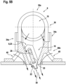
- Figure 3B depicts a schematic cross-sectional view of the PSU 2.
- the PSU 2 comprises at least one oxygen reservoir 23, e.g. an oxygen candle, which is shown on the right side of Figure 3B , and which is not visible in Figure 3A .
- the oxygen reservoir 23 is in fluid communication with at least one oxygen mask 27 by means of a flexible hose 7 for delivering oxygen to the oxygen mask 27, in case of a loss of air pressure within the cabin.
- the oxygen mask 27 is arranged in a cavity 29 covered by a cover 10. Although only one oxygen mask 27 is visible in the cross-sectional view depicted in Figure 3B , the PSU 2 comprises a plurality of oxygen masks 27 arranged in one or more cavities 29. in the event of pressure loss within the passenger cabin 102, the cover 10 will open, the oxygen masks 27 will drop out of the cavity 29, and each of the passengers sitting below the PSU 2 may grasp one of the oxygen masks 27. The oxygen masks 27 will be supplied with oxygen from the oxygen reservoir 23, allowing the passengers to continue breathing normally.
- the cover 10 is pivotable around a horizontally extending axle 44, arranged at a first side of the cover 10.
- a switchable locking mechanism 46 preventing the cover 10 to pivot around the axle 44 in its locked state, is provided at a second side of the cover 10, which is opposite to the axle 44. In the event of pressure loss within the cabin, the locking mechanism 46 will open, allowing the cover 10 to pivot around the axle 44, providing access to the cavity 29, and releasing the oxygen mask(s) 27 stored within the cavity 29.
- a row of three adjacent aircraft passenger cabin gaspers 8, in the following called “gaspers” 8, are provided next to the cavity 29.
- the gaspers 8 are configured for blowing air towards the passengers, sitting on the passenger seats 82 below the PSU 2.
- the gaspers 8 have rectangular or nearly rectangular cross-sections.
- the gaspers 8 in particular have a longitudinal air outlet for delivering air towards the passengers. Details of the gaspers 8 will be discussed below with reference to Figures 4 to 7 .
- Six electrical switches 6a, 6b are provided next to gaspers 8, on the side of the gaspers 8 distal from the cavity 29.
- a pair of two switches 6a, 6b are arranged next to each of the gaspers 8, respectively.
- a first switch 6a of each pair of switches 6a, 6b is configured for switching an adjacent reading light 4, which is arranged next to the switches 6a, 6b on the side opposite to the gaspers 8.
- the second switch 6b of each pair is a call button for triggering a signal for calling cabin service personnel.
- a loudspeaker 11 (see Figure 3A ), which may be used for delivering acoustic announcements to the passengers, is arranged next to the reading lights 4. The side of the loudspeaker 11 facing the passengers is covered by covering 12.
- a display panel 14 including at least one visual sign (not shown), such as a "non smoking” sign and/or “fasten seat belt” sign.
- the display panel 14 comprises at least one light source 13 for selectively illuminating the visual sign from behind, in order to deliver visual information to the passengers sitting below the PSU 2.
- An electric (printed) circuit board (PCB) 5 is arranged between the reading lights 4 and the gaspers 8.
- the electric circuit board 5 is electrically connected to the electrical components of the PSU 2, i.e. the loudspeaker 11, the reading lights 4, the switches 6, and a light source 13 of the display panel 14, by means of a plurality of electric wires 3.
- the PSU 2 depicted in Figures 3A and 3B is configured for being installed above a seating row 80, comprising three passenger seats 82.
- Alternative embodiments of PSUs 2, which are not explicitly depicted in the figures, may comprise more or less reading lights 4, switches 6a, 6b, and/or gaspers 8, in order to be arranged above seating rows 80 comprising more or fewer passenger seats 82.
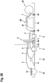
- Figure 4A depicts a perspective view of a gasper 8, which is an illuminated gasper 8 according to an exemplary embodiment of the invention.
- the gasper 8 is shown without the PSU 2.
- the gasper 8 comprises a housing 36 including an upper portion 36a and a lower portion 36b.
- the upper portion 36a is fixed to the lower portion 36b by means of a snap-on mechanism, comprising elastic latches 34a, formed at the upper portion 36a, which are configured for engaging with corresponding protrusions 34b, formed at the lower portion 36b of the housing 36.
- the latches 34a may be formed at the lower portion 36b, and the protrusions 34b may be formed at the upper portion 36a.
- Other types of fixing mechanisms may be employed as well.
- the upper portion 36a for example, may be glued to the lower portion 36b.
- Figure 5A depicts a longitudinal cross-sectional view through the gasper 8, depicted in Figures 4A to 4C ; and Figure 5B depicts a further cross-sectional view of said gasper 8, with the cross-sectional plane of Figure 5B being indicated by dashed line C-C in Figure 5A .
- the air channel 16 is cylindrical around the longitudinal axis A.
- the air channel 16 may for example have an elliptical or a polygonal cross-section, in particular a rectangular, hexagonal or octagonal cross-section.
- the air channel 16 has an air inlet 15 at a first end 16a, shown on the right side of Figures 4A , 4C , and 5A , which is in fluid communication with an air source 19 (see Figure 5A ).
- the air source 19 is configured for delivering air into the air channel 16.
- the air source 19 may include a fan 45, arranged next to the gasper 8, which is configured for sucking air from the environment and deliver said air into the air inlet 15 of the gasper 8.
- the air source 19 also may include an air duct of an aircraft air conditioning system, supplying air to the gasper 8.
- a second end 16b of the air channel 16, which is arranged opposite to the first end 16a, is sealed in an air-tight manner, e.g. by a plug 17.
- An air outlet 18 is formed within the lower portion 36b of the housing 36 (see Figure 5A ).
- the gasper 8 When the gasper 8 is installed within a PSU 2 above the passenger seats 82 in an aircraft passenger cabin 102, as it is depicted in Figure 2 , the air outlet 18 is oriented downwards towards the passenger seats 82. As a result, air delivered into the air channel 16 via the air inlet 15 exits the air channel 16 via the air outlet 18 in a direction towards a passenger seat 82 arranged below the gasper 8.
- an air guide 9 is arranged within the air outlet 18.
- the air guide 9 includes a longitudinal air guide element 20 extending in a longitudinal direction parallel to the longitudinal axis A, and a plurality of transverse air guide elements 22 mounted to the longitudinal air guide element 20.
- the transverse air guide elements 22 are mounted to the longitudinal air guide element 20 in a configuration allowing the transverse air guide elements 22 to pivot with respect to the longitudinal air guide element 20.
- Figure 6 depicts a perspective view of the air guide 9 with a plurality of, in particular seven, transverse air guide elements 22 mounted to the longitudinal air guide element 20.
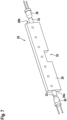
- Figure 7 depicts a perspective view of a longitudinal air guide element 20 without the transverse air guide elements 22.
- Each transverse air guide element 22 is mounted to the longitudinal air guide element 20 via a first axle 24, allowing the transverse air guide element 22 to pivot with respect to the longitudinal air guide element 20.
- the first axles 24 form transverse axes, which are oriented transversely, in particular orthogonally, to the longitudinal direction.
- Each transverse air guide element 22 further comprises a second axle 26, extending parallel to the respective first axle 24, in a region above the longitudinal air guide element 20, i.e. on the side of the longitudinal air guide element 20 facing away from the passenger seats 82, when the gasper 8 is installed within the passenger cabin 102.
- the second axles 26 are all linked to a common link 28, extending along the longitudinal air guide element 20.
- the common link 28 is movable, in particular shiftable, in the longitudinal direction by pivoting the transverse air guide elements 22 around their first axles 24, respectively.
- the common link 28 couples the transverse air guide elements 22 mechanically with each other, causing them to pivot simultaneously around their respective first axles 24. In other words, all transverse air guide elements 22 are pivoted simultaneously around their respective first axles 24, when one of the transverse air guide elements 22 is manually pivoted.
- One of the transverse air guide elements 22, in particular the transverse air guide element 22 arranged in the center of the plurality of transverse air guide elements 22, is provided with a protrusion 30, which may be grabbed easily by a passenger for manually pivoting the transverse air guide elements 22.
- a recess 32 is formed in a central portion of the longitudinal air guide element 20, in order to allow moving the protrusion 30 in the longitudinal direction without interfering with the longitudinal air guide element 20.
- Two cylindrical extensions 33 are formed at opposing end surfaces 20a, 20b of the longitudinal air guide element 20.
- the extensions 33 are both arranged on an axis B, extending in the longitudinal direction of the longitudinal air guide element 20.
- the axis B is oriented parallel to the longitudinal axis A of the gasper 8 (cf. Figure 5A ).
- the cylindrical extensions 33 are rotatably supported by support portions 39 of the lower portion 36b of the housing 36 of the gasper 8.
- the cylindrical extensions 33 are further held in position by fixtures 35, extending from the upper portion 36a of the housing 36.
- Each of the fixtures 35 comprises a circular cut out 37 (see Figure 4C ) for accommodating one of the cylindrical extensions 33 in a configuration that allows the longitudinal air guide element 20 to pivot around the axis B (see Figure 5A ).
- the direction of the flow of air leaving the gasper 8 through the air outlet 18 is adjustable in two dimensions, namely (a) by pivoting the at least one longitudinal air guide element 20 around the axis B and (b) by pivoting the transverse air guide elements 22 around the respective first axles 24 extending transversely to the axis B, as it has been discussed before.
- the gasper 8 may comprise a plurality of air guides 9 arranged parallel to each other within the air outlet 18 of the gasper 8.
- the longitudinal and transverse air guide elements 20, 22 may form a two-dimensional grid of air guide elements 20, 22.
- Two light sources 38 are arranged next to the extensions 33 of the longitudinal air guide element 20 for coupling light into the longitudinal air guide element 20 via the extensions 33.
- the light sources 38 may in particular be arranged on the axis B and oriented coaxially with the cylindrical extensions 33.
- the longitudinal air guide element 20, including the extensions 33 is at least partially transparent or translucent, in order to allow the light emitted by the light sources 38 to propagate therethrough.
- the transverse air guide elements 22 may be at least partially transparent or translucent as well.
- the light coupled from the light sources 38 into the extensions 33 may be reflected one or more times at the outer boundaries (surfaces) of the longitudinal air guide element 20.
- light is coupled out of the longitudinal air guide element 20 into the aircraft passenger cabin 102 via a light output surface 21, formed at the lower side of the longitudinal air guide element 20 and facing the passenger seats 82, which are not shown in Figure 5A .
- the longitudinal air guide element 20 acts as a light guide 25 for the light emitted by the light sources 38.
- the light sources 38 When the light sources 38 are operated, light propagates inside the longitudinal air guide element 20 and is coupled out via the light output surface 21.
- the longitudinal air guide element 20 appears as an extended illuminated / glowing structure. Passengers will not have any difficulties in finding and identifying the gaspers 8 for adjusting the flow of air, flowing out of the gaspers 8, even in a dark environment.
- the light emitted via the longitudinal air guide elements 20 of the gaspers 8 may be used as a signal, e.g. for indicating that a service call button 6b was pressed by a passenger.
- the light may be coupled out of the longitudinal air guide element 20 by any suitable out-coupling mechanism.
- surface irregularities may be provided at one or more of the outer surfaces of the longitudinal air guide element 20.
- the surface irregularities may reflect at least some of the incident light diffusely.
- the diffuse reflections may then hit the light output surface 21 below the critical angle and may be coupled out of the longitudinal air guide element 20 at the light output surface 21.
- Such a mechanism is indicated in Figure 5A via exemplary light rays that originate at the upper surface of the longitudinal air guide element 20, i.e. at the surface opposite to the light output surface 21, travel through the longitudinal air guide element 20, and leave the longitudinal air guide element 20 at the light output surface 21.
- These exemplary light rays may be due to surface irregularities at said upper surface of the longitudinal air guide element 20. It is pointed out that other mechanisms for coupling light out of the light guide may be employed as well.
- each of the light sources 38, associated with each of the longitudinal air guide elements 20 may emit light of the same color.
- each of the light sources 38, associated with a longitudinal air guide element 20 may be configured to emit light having a color which differs from the color of the light emitted by the other light source(s) 38 associated with the same longitudinal air guide element 20.
- At least one of the light sources 38 may be a multi-color light source 38, e.g. a multi-color LED, which is selectively controllable to emit light having a color which is selected from at least two different colors.
- a multi-color light source 38 e.g. a multi-color LED, which is selectively controllable to emit light having a color which is selected from at least two different colors.
- the light sources 38 of different gaspers 8, arranged within a single PSU 2, may be configured for emitting light having the same color.
- the light sources 38 of different gaspers 8 may be configured for emitting light having different colors. Illuminating different gaspers 8 of the same PSU 2 with light having different colors may facilitate identifying the assignment of each gasper 8 to its corresponding passenger seat 82.
- a gasper 8 may further comprise one or more supplementary air channels ("satellite air channels") 40 provided next to the air outlet 18 (see Figures 4A , 4B , and 5B ).
- the satellite air channels 40 are designed so that the flow of air, flowing out of the gasper 8 through the air outlet 18, causes additional air to be sucked through the at least one satellite air channel 40 due to the Venturi effect.
- the additional air is output together with, in particular basically parallel with, the flow of air flowing through the air outlet 18, thereby enhancing the flow of air directed toward the passenger.
- Providing a gasper 8 with one or more satellite air channels 40 is an optional feature, and exemplary embodiments of the present invention include embodiments which do not comprise any satellite air channels 40.
Landscapes
- Engineering & Computer Science (AREA)
- Mechanical Engineering (AREA)
- General Engineering & Computer Science (AREA)
- Aviation & Aerospace Engineering (AREA)
- Thermal Sciences (AREA)
- Physics & Mathematics (AREA)
- Chemical & Material Sciences (AREA)
- Combustion & Propulsion (AREA)
- Health & Medical Sciences (AREA)
- General Health & Medical Sciences (AREA)
- Pulmonology (AREA)
- Air-Conditioning For Vehicles (AREA)
- Arrangements Of Lighting Devices For Vehicle Interiors, Mounting And Supporting Thereof, Circuits Therefore (AREA)
Description
- The present invention is in the field of aircraft passenger cabin gaspers. The present invention is in particular related to illuminated aircraft passenger cabin gaspers.
- Passenger aircraft, such as commercial air planes, usually have a passenger cabin with a plurality of passenger seats and aircraft passenger cabin gaspers, arranged above the passenger seats for supplying air towards passengers sitting on the passenger seats. The aircraft passenger cabin gaspers are typically adjustable, in order to allow modifying the direction and/or the amount of air delivered towards the passengers.
-
DE 20 2009 005100 U1 discloses an air nozzle, for conducting an air flow from an air supply duct for heating, ventilation and air conditioning installations, in particular for a motor vehicle. The air nozzle comprises a housing, which is usable in or behind a wall opening, and which has a connection at the back for an air supply channel, an air flow opening in the front, and a nozzle diverting at least the flow of air. A swivel is provided inside the housing. Narrow splines or spacers, which extend transverse to the longitudinal direction of the end piece, are provided in the swivel or on the back of the swivel for supporting a support on at least one light element. - Document
US2012083195 discloses an air nozzle for conducting air flows, particularly for heating, air conditioning and ventilation systems in motor vehicles, comprising at least one housing, a shaft having air removal disks attached thereto, and a rotary drive for adjusting the shaft. In order to enable a high degree of design freedom, the air nozzle is characterized in that the housing of the air nozzle comprises an air outlet channel having a longitudinally curved structure, or such an air outlet channel is attached to a housing, and the shaft is a flexible shaft or a universal shaft, and the air removal disks are attached to the shaft in a fixed or loose but rotationally secured manner and rotate with the shaft. - In a dark environment, for example when the light within the passenger cabin is dimmed low or switched off, passengers may have difficulties in finding the corresponding gasper(s) for adjusting the flow of air, delivered by the gasper(s), according to their current desire.
- Therefore, it would be beneficial to provide an improved aircraft passenger cabin gasper, which may be identified more easily in a dark environment.
- Exemplary embodiments of the invention include an illuminated aircraft passenger cabin gasper according to independent claim 1. Dependent claims 2 to 11 comprise optional features of an illuminated aircraft passenger cabin gasper according to exemplary embodiment of the invention.
- With the structure of an illuminated aircraft passenger cabin gasper according to the invention, operating the at least one light source may allow for light propagation within the at least one light guide and an output of light towards the passenger via the light output surface. Light from the light guide may thus allow passengers to easily identify and locate the gasper, even in a dark environment. In consequence, even in a dark environment, passengers have no difficulties in adjusting the flow of air flowing out of the gaspers.
- Additionally or alternatively, the light emitted via the light output surface of the at least one light guide of the gasper may be used as an indicator signal, e.g. for indicating that a service call button was pressed by a passenger.
- In an embodiment, the light guide comprises transparent material or translucent material, forming an extended body that allows light to pass through / propagate therein. The light guide may in particular be completely made of a transparent or translucent material. Alternatively, the light guide may comprise a combination of transparent / translucent material and opaque material. A light guide made completely of a transparent or translucent material allows for maximum light transmission. A light guide comprising a combination of transparent / translucent material and opaque material allows for shaping the light output according to the respective needs by selectively arranging the transparent/translucent and opaque materials within the light guide.
- The extended body may be at least partially surrounded by border surfaces, a painting and/or a coating, configured for reflecting the light propagating through the at least one light guide, in order to prevent the light from undesirably coupling out of the at least one light guide. Preventing light from undesirably coupling out of the at least one light guide enhances the optical efficiency of the at least one light guide, it in particular increases the intensity of the light emitted via the dedicated light output surface and avoids or at least reduces the generation of undesirable stray light.
- In an embodiment, surface irregularities are formed on or within at least one surface of the at least one light guide, in order to allow light, propagating through the at least one light guide, to be coupled out of the at least one light guide into the passenger cabin. The surface irregularities may in particular be formed for causing a sufficient amount of light to be output via the dedicated light output surface, preventing the light, propagating through the at least one light guide, from being (totally) reflected at the surfaces of the at least one light guide.
- In an embodiment, the light output surface is an extended surface and light is output through various portions / areas of the extended surface.
- In an embodiment, the at least one light guide comprises at least one light entry surface facing the at least one light source for receiving light from the at least one light source and coupling said light into the at least one light guide. In an embodiment, the at least one light entry surface is arranged transversely, in particular basically orthogonally, to the light output surface. Such a configuration allows for a convenient and space-saving arrangement of the at least one light source within the gasper.
- In an embodiment, the gasper comprises a housing with a support portion supporting the at least one air guide, in particular pivotably supporting the at least one air guide.
- In an embodiment, the at least one light guide has a generally cuboid structure. A light guide having a generally cuboid structure is easy to produce and allows for a convenient structure of the housing pivotably supporting the at least one light guide.
- In an embodiment, the housing comprises an air inlet for receiving air to be output via the air outlet. The air inlet may be in fluid communication with an air duct for receiving the air via the air duct, e.g. from a central air supply of the aircraft.
- In an embodiment, the air inlet is in fluid communication with a fan, which is configured for delivering air from the direct environment of the gasper into the air inlet. The fan may be part of the gasper or part of an aircraft passenger cabin service unit (PSU), comprising at least the gasper and the fan.
- In an embodiment, the housing comprises an upper portion and a lower portion. The air outlet with the at least one air guide may be located in the lower portion, and the air inlet may be provided in the upper portion of the housing.
- In an embodiment, the upper portion of the housing is fixed to the lower portion of the housing by means of a snap-on mechanism, comprising elastic latches formed at the upper portion and configured for engaging corresponding protrusions formed at the lower portion of the housing.
- In another embodiment, the latches may be formed at the lower portion, and the protrusions may be formed at the upper portion.
- In an embodiment, adjusting the flow of air by moving the at least one air guide includes changing the direction and/or changing the volume of the flow of air flowing out of the air outlet.
- In an embodiment, the at least one light guide is a portion of or attached to the at least one air guide. Such a configuration allows shaping the at least one light guide and the at least one air guide individually in order to be optimized with respect to their respective functions.
- In an embodiment, the at least one air guide is basically identical with the at least one light guide. Each light guide may simultaneously function as an air guide. A single guide element, simultaneously providing the functions of an air guide and of a light guide, allows for a little complex configuration, which may be produced at low costs.
- In an embodiment, the gasper comprises at least two light sources. The at least two light sources may be arranged on opposite sides of the at least one light guide for coupling light into the at least one light guide. The at least two light sources may emit light of the same color or light having different colors.
- Each of the light sources may be a single-color light source, which is capable of emitting only light of a single predefined color / a single predefined color spectrum. Alternatively, at least one of the light sources may be a multi-color light source, e.g. a multi-color LED, which is controllable to selectively emit light having a color which is selected from a plurality of different colors.
- Providing light sources which emit light of the same color allows for a very homogeneous illumination of the at least one light guide. Providing two or more light sources which are capable of emitting light having different colors allows for changing the color of the light, emitted from the at least one light guide, by selectively controlling / switching the at least two light sources. With such a configuration, the color of the light emitted from the at least one light guide may be changed according to the passengers' preferences or for providing a signal displaying information. Emitting light of a predefined color may for example indicate that a service call button was pressed by a passenger.
- In an embodiment, the at least one air guide is pivotable around a longitudinal axis, i.e. around an axis extending in the longitudinal direction, in order to allow adjusting the direction of the flow of air flowing out of the gasper via the air outlet.
- In an embodiment, the at least one light source is arranged basically on said longitudinal axis and/or is arranged in such a way that a main light emission direction of the at least one light source substantially corresponds with said longitudinal axis. As a result, the position of the at least one light source with respect to the at least one air guide does not change when the at least one air guide is pivoted around the longitudinal axis.
- In an embodiment, the at least one air guide comprises at least one longitudinal air guide element, extending in the longitudinal direction, and at least one transverse air guide element, extending transversely to the longitudinal direction. The at least one transverse air guide element may in particular be mounted to the longitudinal air guide element in a configuration which allows the at least one transverse air guide element to pivot with respect to the longitudinal air guide element. Providing at least one longitudinal air guide element and at least one additional transverse air guide element, which is pivotable with respect to the at least one longitudinal air guide element, allows adjusting the direction of the flow of air in two dimensions, namely in the longitudinal direction and in a lateral direction, which is oriented transversely, in particular orthogonally, to the longitudinal direction. The light guide may be the longitudinal air guide element or may be part of the longitudinal air guide element.
- In an embodiment, each transverse air guide element is pivotable around a corresponding transverse axis, which is oriented orthogonally to the longitudinal direction.
- In an embodiment, the plurality of transverse air guide elements are pivotably connected to a common link extending in the longitudinal direction. The common link is movable, in particular shiftable, in the longitudinal direction by pivoting at least one of the plurality of transverse air guide elements. A motion of the common link in the longitudinal direction corresponds to a pivoting motion of the plurality of transverse air guide elements. The plurality of transverse air guide elements are mechanically coupled with each other by the common link, so that pivoting one of the plurality of transverse air guide elements may cause all transverse air guide elements to pivot simultaneously.
- In an embodiment, the gasper comprises a plurality of air guides arranged parallel to each other, so that the longitudinal and transverse air guide elements of the plurality of air guides may form an air outlet grid. An air outlet grid may be a very efficient way to adjust the flow of air, flowing out of the air outlet of the gasper.
- In an embodiment, the gasper comprises at least one additional air channel, which in the following is called satellite air channel. The at least one satellite air channel is formed next to the air outlet, so that air flowing through the air outlet causes additional air to be sucked, due to the Venturi effect, through the at least one satellite air channel and to be output together with, in particular basically parallel with, the flow of air, flowing through the air outlet. Providing at least one satellite air channel efficiently enhances the flow of air delivered towards the passenger.
- Exemplary embodiments of the invention further include an aircraft passenger cabin service unit, comprising at least one gasper according to any of the exemplary embodiments of the invention, as described herein. The aircraft passenger cabin service unit may further comprise at least one additional component of the group including a reading light, an oxygen mask, a loudspeaker, a display panel comprising at least one visual sign, such as a "no smoking" sign and/or a "fasten your seat belt" sign, and an electrical switch. The aircraft passenger cabin service unit may also comprise any combination of components including at least two of these components. The aircraft passenger cabin service unit may also comprise multiple instances of any of the listed additional components.
- In an embodiment, the aircraft passenger cabin service unit comprises at least two aircraft passenger cabin gaspers according to any of the exemplary embodiments of the invention, as described herein. In such an embodiment, the light sources of the different gaspers may be configured for emitting light of the same color. Alternatively, the light sources of the different gaspers may be configured for emitting light of different colors. In a configuration in which the light sources of the different gaspers are configured for emitting light of different colors, the gaspers may be distinguished from each other by the different colors of the emitted light. The different colors, for example, may be used for indicating the relation between the gasper and a corresponding passenger seat, e.g. by providing a marker of the same color at the corresponding passenger seat.
- Exemplary embodiments of the invention further include an aircraft, in particular a passenger air plane, comprising a passenger cabin with a plurality of aircraft passenger cabin gaspers according to any of the exemplary embodiments of the invention, as described herein.
- Exemplary embodiments of the invention also include an aircraft, in particular a passenger air plane, comprising a passenger cabin with a plurality of aircraft passenger cabin service units according to exemplary embodiments of the invention.
- Further exemplary embodiments of the invention will be described with respect to the accompanying drawings, wherein:
-
Figure 1 depicts a schematic side view of an aircraft in accordance with an exemplary embodiment of the invention having a passenger cabin. -
Figure 2 depicts a longitudinal cross-sectional view of a portion of the passenger cabin of the aircraft shown inFigure 1 . -
Figure 3A depicts an aircraft passenger cabin service unit, as it is seen from a passenger sitting on one of the passenger seats. -
Figure 3B depicts a schematic cross-sectional view through the aircraft passenger cabin service unit shown inFigure 3A . -
Figure 4A depicts a perspective view of a gasper according to an exemplary embodiment of the invention. -
Figure 4B depicts a perspective view of the gasper shown inFigure 4A , with the upper portion of the housing being removed. -
Figure 4C depicts a perspective view of the upper portion of the housing of the gasper shown inFigure 4A . -
Figure 5A depicts a longitudinal cross-sectional view through the gasper depicted inFigures 4A to 4C . -
Figure 5B depicts a cross-sectional view of said gasper, with the cross-sectional plane being orthogonal to the cross-sectional plane ofFigure 5A . -
Figure 6 depicts a perspective view of an air guide, including a single longitudinal air guide element and a plurality of transverse air guide elements, the air guide being usable in a gasper according to an exemplary embodiment of the invention. -
Figure 7 depicts a perspective view of a longitudinal air guide element without the transverse air guide elements. -
Figure 1 shows a schematic side view of anaircraft 100, in particular anair plane 100, with apassenger cabin 102.Figure 2 shows a longitudinal cross-sectional view of a portion of thepassenger cabin 102 of theaircraft 100, depicted inFigure 1 . - Four
passenger seats 82 are depicted inFigure 2 . The passenger seats 82 are mounted to afloor 110 of thepassenger cabin 102. Each of the depictedpassenger seats 82 belongs to adifferent seating row 80. Eachseating row 80 includes a plurality of, for example three, passenger seats 82. The additional (second and third) passenger seats 82 of eachseating row 80 are not visible inFigure 2 , as they are arranged behind and therefore hidden by the depicted first passenger seats 82, respectively. - For each of the
seating rows 80, awindow 108 is provided, which allows the passengers to view the outside of theaircraft 100. Further, a plurality of overhead baggage compartments 112 are shown, which provide storage space for baggage. - An aircraft passenger cabin service unit ("PSU") 2 is arranged above each of the
seating rows 80, respectively. -
Figure 3A depicts a schematic view ofPSU 2, as it is seen from a passenger (not shown) sitting on one of the passenger seats 82 below thePSU 2.Figure 3B depicts a schematic cross-sectional view of thePSU 2. - The
PSU 2 comprises at least one oxygen reservoir 23, e.g. an oxygen candle, which is shown on the right side ofFigure 3B , and which is not visible inFigure 3A . The oxygen reservoir 23 is in fluid communication with at least oneoxygen mask 27 by means of a flexible hose 7 for delivering oxygen to theoxygen mask 27, in case of a loss of air pressure within the cabin. - The
oxygen mask 27 is arranged in acavity 29 covered by acover 10. Although only oneoxygen mask 27 is visible in the cross-sectional view depicted inFigure 3B , thePSU 2 comprises a plurality ofoxygen masks 27 arranged in one ormore cavities 29. in the event of pressure loss within thepassenger cabin 102, thecover 10 will open, theoxygen masks 27 will drop out of thecavity 29, and each of the passengers sitting below thePSU 2 may grasp one of theoxygen masks 27. Theoxygen masks 27 will be supplied with oxygen from the oxygen reservoir 23, allowing the passengers to continue breathing normally. - The
cover 10 is pivotable around a horizontally extendingaxle 44, arranged at a first side of thecover 10. Aswitchable locking mechanism 46, preventing thecover 10 to pivot around theaxle 44 in its locked state, is provided at a second side of thecover 10, which is opposite to theaxle 44. In the event of pressure loss within the cabin, thelocking mechanism 46 will open, allowing thecover 10 to pivot around theaxle 44, providing access to thecavity 29, and releasing the oxygen mask(s) 27 stored within thecavity 29. - A row of three adjacent aircraft
passenger cabin gaspers 8, in the following called "gaspers" 8, are provided next to thecavity 29. Thegaspers 8 are configured for blowing air towards the passengers, sitting on the passenger seats 82 below thePSU 2. Thegaspers 8 have rectangular or nearly rectangular cross-sections. Thegaspers 8 in particular have a longitudinal air outlet for delivering air towards the passengers. Details of thegaspers 8 will be discussed below with reference toFigures 4 to 7 . - Six
electrical switches gaspers 8, on the side of thegaspers 8 distal from thecavity 29. A pair of twoswitches gaspers 8, respectively. Afirst switch 6a of each pair ofswitches adjacent reading light 4, which is arranged next to theswitches gaspers 8. Thesecond switch 6b of each pair is a call button for triggering a signal for calling cabin service personnel. - A loudspeaker 11 (see
Figure 3A ), which may be used for delivering acoustic announcements to the passengers, is arranged next to the reading lights 4. The side of theloudspeaker 11 facing the passengers is covered by covering 12. - Next to the
loudspeaker 11, there is adisplay panel 14, including at least one visual sign (not shown), such as a "non smoking" sign and/or "fasten seat belt" sign. - The
display panel 14 comprises at least onelight source 13 for selectively illuminating the visual sign from behind, in order to deliver visual information to the passengers sitting below thePSU 2. - An electric (printed) circuit board (PCB) 5 is arranged between the reading
lights 4 and thegaspers 8. The electric circuit board 5 is electrically connected to the electrical components of thePSU 2, i.e. theloudspeaker 11, thereading lights 4, the switches 6, and alight source 13 of thedisplay panel 14, by means of a plurality ofelectric wires 3. - The
PSU 2 depicted inFigures 3A and3B is configured for being installed above aseating row 80, comprising threepassenger seats 82. Alternative embodiments ofPSUs 2, which are not explicitly depicted in the figures, may comprise more orless reading lights 4,switches gaspers 8, in order to be arranged aboveseating rows 80 comprising more or fewer passenger seats 82. -
Figure 4A depicts a perspective view of agasper 8, which is anilluminated gasper 8 according to an exemplary embodiment of the invention. InFigure 4A and the following figures, thegasper 8 is shown without thePSU 2. - The
gasper 8 comprises ahousing 36 including anupper portion 36a and alower portion 36b. Theupper portion 36a is fixed to thelower portion 36b by means of a snap-on mechanism, comprisingelastic latches 34a, formed at theupper portion 36a, which are configured for engaging with correspondingprotrusions 34b, formed at thelower portion 36b of thehousing 36. In another configuration, which is not explicitly shown in the figures, thelatches 34a may be formed at thelower portion 36b, and theprotrusions 34b may be formed at theupper portion 36a. Other types of fixing mechanisms may be employed as well. Theupper portion 36a, for example, may be glued to thelower portion 36b. - In
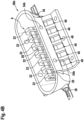
Figure 4B , thelower portion 36b of thehousing 36 is shown without theupper portion 36a, in order to allow an insight into the trough-shapedlower portion 36b of thehousing 36. Theupper portion 36a of thehousing 36 is shown again inFigure 4C . - Further details of the
gasper 8 will be described below with respect toFigures 5 to 7 . Various features are also visible inFigures 4A and4B , as will be apparent from a comparison ofFigures 4A and4B on the one hand andFigures 5 to 7 on the other hand. -
Figure 5A depicts a longitudinal cross-sectional view through thegasper 8, depicted inFigures 4A to 4C ; andFigure 5B depicts a further cross-sectional view of saidgasper 8, with the cross-sectional plane ofFigure 5B being indicated by dashed line C-C inFigure 5A . - An
air channel 16, extending along a longitudinal axis A, is formed within theupper portion 36a of thehousing 36. In the embodiment depicted in the figures, theair channel 16 is cylindrical around the longitudinal axis A. The cylindrical shape of theair channel 16, however, is only exemplary, and theair channel 16 may have other shapes as well. Theair channel 16 may for example have an elliptical or a polygonal cross-section, in particular a rectangular, hexagonal or octagonal cross-section. - The
air channel 16 has anair inlet 15 at afirst end 16a, shown on the right side ofFigures 4A ,4C , and5A , which is in fluid communication with an air source 19 (seeFigure 5A ). Theair source 19 is configured for delivering air into theair channel 16. Theair source 19 may include afan 45, arranged next to thegasper 8, which is configured for sucking air from the environment and deliver said air into theair inlet 15 of thegasper 8. Theair source 19 also may include an air duct of an aircraft air conditioning system, supplying air to thegasper 8. Asecond end 16b of theair channel 16, which is arranged opposite to thefirst end 16a, is sealed in an air-tight manner, e.g. by aplug 17. - An
air outlet 18 is formed within thelower portion 36b of the housing 36 (seeFigure 5A ). When thegasper 8 is installed within aPSU 2 above the passenger seats 82 in anaircraft passenger cabin 102, as it is depicted inFigure 2 , theair outlet 18 is oriented downwards towards the passenger seats 82. As a result, air delivered into theair channel 16 via theair inlet 15 exits theair channel 16 via theair outlet 18 in a direction towards apassenger seat 82 arranged below thegasper 8. - In order to facilitate adjusting the direction of the flow of air, flowing out of the
gasper 8 via theair outlet 18, anair guide 9 is arranged within theair outlet 18. Theair guide 9 includes a longitudinalair guide element 20 extending in a longitudinal direction parallel to the longitudinal axis A, and a plurality of transverseair guide elements 22 mounted to the longitudinalair guide element 20. The transverseair guide elements 22 are mounted to the longitudinalair guide element 20 in a configuration allowing the transverseair guide elements 22 to pivot with respect to the longitudinalair guide element 20. -
Figure 6 depicts a perspective view of theair guide 9 with a plurality of, in particular seven, transverseair guide elements 22 mounted to the longitudinalair guide element 20.Figure 7 depicts a perspective view of a longitudinalair guide element 20 without the transverseair guide elements 22. - Each transverse
air guide element 22 is mounted to the longitudinalair guide element 20 via afirst axle 24, allowing the transverseair guide element 22 to pivot with respect to the longitudinalair guide element 20. Thefirst axles 24 form transverse axes, which are oriented transversely, in particular orthogonally, to the longitudinal direction. - Each transverse
air guide element 22 further comprises asecond axle 26, extending parallel to the respectivefirst axle 24, in a region above the longitudinalair guide element 20, i.e. on the side of the longitudinalair guide element 20 facing away from the passenger seats 82, when thegasper 8 is installed within thepassenger cabin 102. - The
second axles 26 are all linked to acommon link 28, extending along the longitudinalair guide element 20. - The
common link 28 is movable, in particular shiftable, in the longitudinal direction by pivoting the transverseair guide elements 22 around theirfirst axles 24, respectively. Thecommon link 28 couples the transverseair guide elements 22 mechanically with each other, causing them to pivot simultaneously around their respectivefirst axles 24. In other words, all transverseair guide elements 22 are pivoted simultaneously around their respectivefirst axles 24, when one of the transverseair guide elements 22 is manually pivoted. - One of the transverse
air guide elements 22, in particular the transverseair guide element 22 arranged in the center of the plurality of transverseair guide elements 22, is provided with aprotrusion 30, which may be grabbed easily by a passenger for manually pivoting the transverseair guide elements 22. - A
recess 32 is formed in a central portion of the longitudinalair guide element 20, in order to allow moving theprotrusion 30 in the longitudinal direction without interfering with the longitudinalair guide element 20. - Two
cylindrical extensions 33 are formed at opposingend surfaces air guide element 20. Theextensions 33 are both arranged on an axis B, extending in the longitudinal direction of the longitudinalair guide element 20. When the longitudinalair guide element 20 is arranged within theair outlet 18 of thegasper 8, the axis B is oriented parallel to the longitudinal axis A of the gasper 8 (cf.Figure 5A ). - The
cylindrical extensions 33 are rotatably supported bysupport portions 39 of thelower portion 36b of thehousing 36 of thegasper 8. Thecylindrical extensions 33 are further held in position byfixtures 35, extending from theupper portion 36a of thehousing 36. Each of thefixtures 35 comprises a circular cut out 37 (seeFigure 4C ) for accommodating one of thecylindrical extensions 33 in a configuration that allows the longitudinalair guide element 20 to pivot around the axis B (seeFigure 5A ). - As a result, the direction of the flow of air leaving the
gasper 8 through theair outlet 18 is adjustable in two dimensions, namely (a) by pivoting the at least one longitudinalair guide element 20 around the axis B and (b) by pivoting the transverseair guide elements 22 around the respectivefirst axles 24 extending transversely to the axis B, as it has been discussed before. - In a further configuration, which is not explicitly shown in the figures, the
gasper 8 may comprise a plurality of air guides 9 arranged parallel to each other within theair outlet 18 of thegasper 8. In that case, the longitudinal and transverseair guide elements air guide elements - Two
light sources 38, in particular LEDs, are arranged next to theextensions 33 of the longitudinalair guide element 20 for coupling light into the longitudinalair guide element 20 via theextensions 33. Thelight sources 38 may in particular be arranged on the axis B and oriented coaxially with thecylindrical extensions 33. The longitudinalair guide element 20, including theextensions 33, is at least partially transparent or translucent, in order to allow the light emitted by thelight sources 38 to propagate therethrough. Optionally, the transverseair guide elements 22 may be at least partially transparent or translucent as well. - As schematically illustrated in
Figure 5A , the light coupled from thelight sources 38 into theextensions 33 may be reflected one or more times at the outer boundaries (surfaces) of the longitudinalair guide element 20. Eventually, light is coupled out of the longitudinalair guide element 20 into theaircraft passenger cabin 102 via alight output surface 21, formed at the lower side of the longitudinalair guide element 20 and facing the passenger seats 82, which are not shown inFigure 5A . - Thus, the longitudinal
air guide element 20 acts as alight guide 25 for the light emitted by thelight sources 38. When thelight sources 38 are operated, light propagates inside the longitudinalair guide element 20 and is coupled out via thelight output surface 21. The longitudinalair guide element 20 appears as an extended illuminated / glowing structure. Passengers will not have any difficulties in finding and identifying thegaspers 8 for adjusting the flow of air, flowing out of thegaspers 8, even in a dark environment. Additionally or alternatively, the light emitted via the longitudinalair guide elements 20 of thegaspers 8 may be used as a signal, e.g. for indicating that aservice call button 6b was pressed by a passenger. - The light may be coupled out of the longitudinal
air guide element 20 by any suitable out-coupling mechanism. For example, surface irregularities may be provided at one or more of the outer surfaces of the longitudinalair guide element 20. Instead of the specular reflection, which takes place during "normal" light propagation within the longitudinalair guide element 20, the surface irregularities may reflect at least some of the incident light diffusely. The diffuse reflections may then hit thelight output surface 21 below the critical angle and may be coupled out of the longitudinalair guide element 20 at thelight output surface 21. Such a mechanism is indicated inFigure 5A via exemplary light rays that originate at the upper surface of the longitudinalair guide element 20, i.e. at the surface opposite to thelight output surface 21, travel through the longitudinalair guide element 20, and leave the longitudinalair guide element 20 at thelight output surface 21. These exemplary light rays may be due to surface irregularities at said upper surface of the longitudinalair guide element 20. It is pointed out that other mechanisms for coupling light out of the light guide may be employed as well. - When operated, the two
light sources 38, associated with each of the longitudinalair guide elements 20, may emit light of the same color. Alternatively, each of thelight sources 38, associated with a longitudinalair guide element 20, may be configured to emit light having a color which differs from the color of the light emitted by the other light source(s) 38 associated with the same longitudinalair guide element 20. - In yet another embodiment, at least one of the
light sources 38 may be a multi-colorlight source 38, e.g. a multi-color LED, which is selectively controllable to emit light having a color which is selected from at least two different colors. Such a configuration allows for changing the color of the light, emitted via the longitudinalair guide elements 20, by appropriately controlling the operation of thelight sources 38. - The
light sources 38 ofdifferent gaspers 8, arranged within asingle PSU 2, may be configured for emitting light having the same color. Alternatively, thelight sources 38 ofdifferent gaspers 8 may be configured for emitting light having different colors. Illuminatingdifferent gaspers 8 of thesame PSU 2 with light having different colors may facilitate identifying the assignment of eachgasper 8 to itscorresponding passenger seat 82. - A
gasper 8 according to an exemplary embodiment of the invention may further comprise one or more supplementary air channels ("satellite air channels") 40 provided next to the air outlet 18 (seeFigures 4A ,4B , and5B ). Thesatellite air channels 40 are designed so that the flow of air, flowing out of thegasper 8 through theair outlet 18, causes additional air to be sucked through the at least onesatellite air channel 40 due to the Venturi effect. The additional air is output together with, in particular basically parallel with, the flow of air flowing through theair outlet 18, thereby enhancing the flow of air directed toward the passenger. Providing agasper 8 with one or moresatellite air channels 40, however, is an optional feature, and exemplary embodiments of the present invention include embodiments which do not comprise anysatellite air channels 40. - While the invention has been described with reference to exemplary embodiments, it will be understood by those skilled in the art that various changes may be made without departing from the scope of the invention. In addition many modifications may be made to adopt a particular situation or material to the teachings of the invention without departing from the essential scope thereof. Therefore, it is intended that the invention not be limited to the particular embodiment disclosed, but that the invention include all embodiments falling within the scope of the following claims.
Claims (14)
- Illuminated aircraft passenger cabin gasper (8), comprising:an air outlet (18) for outputting a flow of air into an aircraft passenger cabin (102);at least one air guide (9), which is movably arranged within the air outlet (18) for adjusting the flow of air, characterised in that each air guide (9) comprises:at least one longitudinal air guide element (20) extending in a longitudinal direction and a plurality of transverse air guide elements (22) mounted to the at least one longitudinal air guide element (20);wherein the plurality of transverse air guide elements (22) are mounted to the at least one longitudinal air guide element (20) in a configuration which allows the plurality of transverse air guide elements (22) to pivot with respect to the at least one longitudinal air guide element (20); andwherein the plurality of transverse air guide elements (22) are pivotably connected to a common link (28), extending in the longitudinal direction;wherein the illuminated aircraft passenger cabin gasper (8) further comprises:at least one light source (38), arranged adjacent to the at least one longitudinal air guide element (20) for coupling light into the longitudinal air guide element (20); andwherein the at least one longitudinal air guide element (20) has a light output surface (21) for coupling light out of the at least one longitudinal air guide element (20) into the aircraft passenger cabin (102),so that the at least one longitudinal air guide element (20) acts as a light guide for the light emitted by the at least one light source (38).
- Illuminated aircraft passenger cabin gasper (8) according to claim 1, comprising at least two light sources (38) arranged on opposite sides of the at least one light guide (25) for coupling light into the at least one light guide (25).
- Illuminated aircraft passenger cabin gasper (8) according to claim 2, wherein the at least two light sources (38), in operation, emit light of the same color or light having different colors.
- Illuminated aircraft passenger cabin gasper (8) according to any of the preceding claims, wherein the at least one light source (38) is capable of selectively emitting light of different colors.
- Illuminated aircraft passenger cabin gasper (8) according to any of the preceding claims, wherein the at least one air guide (9) is pivotable around a longitudinal axis (A), wherein the at least one light source (38) is in particular arranged basically on said longitudinal axis (A).
- Illuminated aircraft passenger cabin gasper (8) according to any of the preceding claims, wherein each transverse air guide element (22) is pivotable around a corresponding transverse axis which is oriented orthogonally to the longitudinal direction.
- Illuminated aircraft passenger cabin gasper (8) according to claim 6, wherein the common link (28) is movable, in particular shiftable, in the longitudinal direction by pivoting at least one of the plurality of transverse air guide elements (22)
- Illuminated aircraft passenger cabin gasper (8) according to any of the preceding claims, comprising a plurality of air guides (9) arranged parallel to each other forming an air outlet (18) grid.
- Illuminated aircraft passenger cabin gasper (8) according to any of the preceding claims, comprising a housing (36) with at least one support portion (39), supporting the at least one air guide (9), in particular pivotably supporting the at least one air guide (9), wherein the housing (36) comprises an air inlet (15) for receiving the air to be output via the air outlet (18), wherein the illuminated aircraft passenger cabin gasper (8) in particular comprises an air source (19), such as a fan or an air duct, in fluid communication with the air inlet (15) for supplying air into the air inlet (15).
- Illuminated aircraft passenger cabin gasper (8) according to claim 9, wherein the housing (36) comprises an upper portion (36a) and a lower portion (36b), wherein the air outlet (18) with the at least one air guide (9) are in particular located in the lower portion (36b) and the air inlet (15) is in particular provided in the upper portion (36a).
- Illuminated aircraft passenger cabin gasper (8) according to any of the preceding claims, further comprising at least one satellite air channel (40) formed next to the air outlet (18), so that air flowing through the air outlet (18) causes additional air to be sucked through the at least one satellite air channel (40) and to be output together with, in particular basically parallel with, the flow of air flowing through the air outlet (18).
- Aircraft passenger cabin service unit (2), comprising at least one illuminated aircraft passenger cabin gasper (8) according to any of the preceding claims, wherein the aircraft passenger cabin service unit (2) in particular further comprises at least one component of the group including a reading light (4), an oxygen mask (27), a loudspeaker (11), a display panel (14), and an electrical switch (6a, 6b) or any combination including at least two of these components.
- Aircraft passenger cabin service unit (2) according to claim 12, comprising at least two illuminated aircraft passenger cabin gaspers (8) according to any of claims 1 to 12, wherein the light sources (38) of the different illuminated aircraft passenger cabin gaspers (8) are in particular configured for emitting light having different colors.
- Aircraft (100), comprising a passenger cabin and a plurality of aircraft passenger cabin gaspers (8) according to any of claims 1 to 11, in particular comprising a passenger cabin and a plurality of aircraft passenger cabin service units (2) according to claim 12 or 13, located within the aircraft passenger cabin (102).
Priority Applications (2)
| Application Number | Priority Date | Filing Date | Title |
|---|---|---|---|
| EP19210626.8A EP3825232B1 (en) | 2019-11-21 | 2019-11-21 | Illuminated aircraft passenger cabin gasper |
| US16/950,150 US11524794B2 (en) | 2019-11-21 | 2020-11-17 | Illuminated aircraft passenger cabin gasper |
Applications Claiming Priority (1)
| Application Number | Priority Date | Filing Date | Title |
|---|---|---|---|
| EP19210626.8A EP3825232B1 (en) | 2019-11-21 | 2019-11-21 | Illuminated aircraft passenger cabin gasper |
Publications (2)
| Publication Number | Publication Date |
|---|---|
| EP3825232A1 EP3825232A1 (en) | 2021-05-26 |
| EP3825232B1 true EP3825232B1 (en) | 2023-06-07 |
Family
ID=68834939
Family Applications (1)
| Application Number | Title | Priority Date | Filing Date |
|---|---|---|---|
| EP19210626.8A Active EP3825232B1 (en) | 2019-11-21 | 2019-11-21 | Illuminated aircraft passenger cabin gasper |
Country Status (2)
| Country | Link |
|---|---|
| US (1) | US11524794B2 (en) |
| EP (1) | EP3825232B1 (en) |
Families Citing this family (2)
| Publication number | Priority date | Publication date | Assignee | Title |
|---|---|---|---|---|
| DE102019003359A1 (en) * | 2019-05-13 | 2020-11-19 | Daimler Ag | Air vent for a vehicle |
| EP4406840A1 (en) * | 2023-01-24 | 2024-07-31 | B/E Aerospace, Inc. | Smart air gasper in the passenger service unit |
Family Cites Families (23)
| Publication number | Priority date | Publication date | Assignee | Title |
|---|---|---|---|---|
| DE8815072U1 (en) * | 1988-12-03 | 1989-01-19 | Hörauf & Kohler KG, 8900 Augsburg | Illuminated control device for operating a ventilation system or the like in a motor vehicle |
| DE29916755U1 (en) * | 1999-09-23 | 1999-12-09 | Reitter & Schefenacker GmbH & Co. KG, 73730 Esslingen | Air vents in vehicles, preferably motor vehicles |
| US7014557B2 (en) * | 2003-07-23 | 2006-03-21 | Goodrich Hella Aerospace Lighting Systems Gmbh | Outlet device for the interior of a vehicle |
| EP1661806A1 (en) * | 2004-11-26 | 2006-05-31 | Goodrich Lighting Systems GmbH | Air outlet device for a vehicle |
| US7627402B2 (en) | 2005-10-21 | 2009-12-01 | Current Technologies, Llc | Device and method for designing power line communication system networks |
| US7527402B2 (en) | 2006-11-13 | 2009-05-05 | The Boeing Company | Integrated reading light and personal air outlet |
| US10146320B2 (en) | 2007-10-29 | 2018-12-04 | The Boeing Company | Aircraft having gesture-based control for an onboard passenger service unit |
| DE102008051251B4 (en) * | 2008-10-10 | 2013-06-06 | Airbus Operations Gmbh | Supply device for a means of transport |
| DE202009005100U1 (en) * | 2009-08-03 | 2009-11-12 | Dr. Schneider Kunststoffwerke Gmbh | air nozzle |
| DE202009005250U1 (en) * | 2009-09-08 | 2009-11-12 | Dr. Schneider Kunststoffwerke Gmbh | Arched air nozzle |
| US8858047B2 (en) | 2011-02-03 | 2014-10-14 | Zodiac Aerotechnics | Passenger light cooling |
| US9365291B2 (en) | 2012-02-14 | 2016-06-14 | C&D Zodiac, Inc. | Passenger service unit pod assembly |
| US9045235B2 (en) | 2013-07-31 | 2015-06-02 | Zodiac Aerotechnics | Service device, passenger service unit, fuselage of an aircraft, method for installing the service device |
| DE102014018302B4 (en) * | 2014-12-10 | 2023-10-05 | Mercedes-Benz Group AG | Ventilation device |
| EP3156272B1 (en) * | 2015-06-11 | 2017-11-22 | Dr. Schneider Kunststoffwerke GmbH | Air vent |
| EP3168152B1 (en) * | 2015-11-13 | 2018-10-24 | Goodrich Lighting Systems GmbH | Aircraft overhead passenger service unit |
| DE102016000067A1 (en) * | 2016-01-06 | 2017-07-06 | GM Global Technology Operations LLC (n. d. Ges. d. Staates Delaware) | Ventilation nozzle arrangement for a cockpit of a vehicle and vehicle with the ventilation nozzle arrangement |
| DE102016003974A1 (en) * | 2016-04-01 | 2016-09-29 | Daimler Ag | Air vent for a vehicle, in particular for a motor vehicle |
| EP3446030B1 (en) * | 2016-04-22 | 2019-12-18 | Signify Holding B.V. | Pebble-plate like louvre |
| US10752082B1 (en) * | 2016-05-26 | 2020-08-25 | Apple Inc. | Climate control system with slit-vent fluid delivery |
| US20180056758A1 (en) * | 2016-08-31 | 2018-03-01 | Ford Global Technologies, Llc | Vehicle duct with enhanced lighting or cleaning capabilities and related methods |
| KR20200079866A (en) * | 2018-12-26 | 2020-07-06 | 주식회사 니프코코리아 | Air vent lighting system |
| CA3065602A1 (en) * | 2018-12-26 | 2020-06-26 | Bombardier Inc. | Universal passenger service unit |
-
2019
- 2019-11-21 EP EP19210626.8A patent/EP3825232B1/en active Active
-
2020
- 2020-11-17 US US16/950,150 patent/US11524794B2/en active Active
Also Published As
| Publication number | Publication date |
|---|---|
| US11524794B2 (en) | 2022-12-13 |
| US20210155351A1 (en) | 2021-05-27 |
| EP3825232A1 (en) | 2021-05-26 |
Similar Documents
| Publication | Publication Date | Title |
|---|---|---|
| USRE36642E (en) | Fiber-optic lighting system | |
| EP2915699A2 (en) | Aircraft cabin light systems | |
| US8348455B2 (en) | Overhead reading lamp for a passenger seat | |
| EP3825232B1 (en) | Illuminated aircraft passenger cabin gasper | |
| US9487134B2 (en) | Seat back illumination module | |
| US7413327B2 (en) | Vehicle lighting fixture | |
| US8100547B2 (en) | Service apparatus with an illuminator and an air shower | |
| EP3168152B1 (en) | Aircraft overhead passenger service unit | |
| US20120230530A1 (en) | Passenger service unit, passenger service channel and means of transport | |
| US6454209B1 (en) | Comfort and illumination apparatus for a passenger space | |
| US10065741B1 (en) | Illuminated literature pocket for aircraft passenger seat | |
| EP3305659B1 (en) | Methods and devices for light distribution in an aircraft, and aircraft including such devices | |
| CN106352287B (en) | Aircraft interior light unit and method for operating an aircraft interior light unit | |
| KR20140094414A (en) | Air conditioner | |
| WO2006042052A2 (en) | Multicolored led vehicle interior light | |
| KR20140092956A (en) | Air conditioner | |
| US10967785B2 (en) | Aircraft passenger light with reading and halo lighting | |
| US20080013332A1 (en) | Invisible Emergency Lighting for an Aircraft Cabin | |
| WO2019165018A1 (en) | Air vent for a vehicle | |
| JP5658543B2 (en) | Guide light | |
| JP2003223125A (en) | Display device | |
| US11975865B2 (en) | Aircraft passenger cabin light, aircraft passenger cabin lighting system, and method of installing an aircraft passenger cabin lighting system | |
| US4903175A (en) | Illumination module | |
| EP1093968A2 (en) | A motor vehicle provided with a dashboard illumination unit | |
| CN113137382B (en) | Air supply device |
Legal Events
| Date | Code | Title | Description |
|---|---|---|---|
| PUAI | Public reference made under article 153(3) epc to a published international application that has entered the european phase |
Free format text: ORIGINAL CODE: 0009012 |
|
| STAA | Information on the status of an ep patent application or granted ep patent |
Free format text: STATUS: THE APPLICATION HAS BEEN PUBLISHED |
|
| AK | Designated contracting states |
Kind code of ref document: A1 Designated state(s): AL AT BE BG CH CY CZ DE DK EE ES FI FR GB GR HR HU IE IS IT LI LT LU LV MC MK MT NL NO PL PT RO RS SE SI SK SM TR |
|
| RAP3 | Party data changed (applicant data changed or rights of an application transferred) |
Owner name: GOODRICH LIGHTING SYSTEMS GMBH & CO. KG |
|
| STAA | Information on the status of an ep patent application or granted ep patent |
Free format text: STATUS: REQUEST FOR EXAMINATION WAS MADE |
|
| 17P | Request for examination filed |
Effective date: 20211124 |
|
| RBV | Designated contracting states (corrected) |
Designated state(s): AL AT BE BG CH CY CZ DE DK EE ES FI FR GB GR HR HU IE IS IT LI LT LU LV MC MK MT NL NO PL PT RO RS SE SI SK SM TR |
|
| GRAP | Despatch of communication of intention to grant a patent |
Free format text: ORIGINAL CODE: EPIDOSNIGR1 |
|
| STAA | Information on the status of an ep patent application or granted ep patent |
Free format text: STATUS: GRANT OF PATENT IS INTENDED |
|
| INTG | Intention to grant announced |
Effective date: 20220927 |
|
| GRAS | Grant fee paid |
Free format text: ORIGINAL CODE: EPIDOSNIGR3 |
|
| GRAA | (expected) grant |
Free format text: ORIGINAL CODE: 0009210 |
|
| STAA | Information on the status of an ep patent application or granted ep patent |
Free format text: STATUS: THE PATENT HAS BEEN GRANTED |
|
| AK | Designated contracting states |
Kind code of ref document: B1 Designated state(s): AL AT BE BG CH CY CZ DE DK EE ES FI FR GB GR HR HU IE IS IT LI LT LU LV MC MK MT NL NO PL PT RO RS SE SI SK SM TR |
|
| REG | Reference to a national code |
Ref country code: GB Ref legal event code: FG4D |
|
| REG | Reference to a national code |
Ref country code: CH Ref legal event code: EP Ref country code: AT Ref legal event code: REF Ref document number: 1574293 Country of ref document: AT Kind code of ref document: T Effective date: 20230615 Ref country code: DE Ref legal event code: R096 Ref document number: 602019029941 Country of ref document: DE |
|
| REG | Reference to a national code |
Ref country code: LT Ref legal event code: MG9D |
|
| REG | Reference to a national code |
Ref country code: NL Ref legal event code: MP Effective date: 20230607 |
|
| PG25 | Lapsed in a contracting state [announced via postgrant information from national office to epo] |
Ref country code: SE Free format text: LAPSE BECAUSE OF FAILURE TO SUBMIT A TRANSLATION OF THE DESCRIPTION OR TO PAY THE FEE WITHIN THE PRESCRIBED TIME-LIMIT Effective date: 20230607 Ref country code: NO Free format text: LAPSE BECAUSE OF FAILURE TO SUBMIT A TRANSLATION OF THE DESCRIPTION OR TO PAY THE FEE WITHIN THE PRESCRIBED TIME-LIMIT Effective date: 20230907 Ref country code: ES Free format text: LAPSE BECAUSE OF FAILURE TO SUBMIT A TRANSLATION OF THE DESCRIPTION OR TO PAY THE FEE WITHIN THE PRESCRIBED TIME-LIMIT Effective date: 20230607 |
|
| REG | Reference to a national code |
Ref country code: AT Ref legal event code: MK05 Ref document number: 1574293 Country of ref document: AT Kind code of ref document: T Effective date: 20230607 |
|
| PG25 | Lapsed in a contracting state [announced via postgrant information from national office to epo] |
Ref country code: RS Free format text: LAPSE BECAUSE OF FAILURE TO SUBMIT A TRANSLATION OF THE DESCRIPTION OR TO PAY THE FEE WITHIN THE PRESCRIBED TIME-LIMIT Effective date: 20230607 Ref country code: NL Free format text: LAPSE BECAUSE OF FAILURE TO SUBMIT A TRANSLATION OF THE DESCRIPTION OR TO PAY THE FEE WITHIN THE PRESCRIBED TIME-LIMIT Effective date: 20230607 Ref country code: LV Free format text: LAPSE BECAUSE OF FAILURE TO SUBMIT A TRANSLATION OF THE DESCRIPTION OR TO PAY THE FEE WITHIN THE PRESCRIBED TIME-LIMIT Effective date: 20230607 Ref country code: LT Free format text: LAPSE BECAUSE OF FAILURE TO SUBMIT A TRANSLATION OF THE DESCRIPTION OR TO PAY THE FEE WITHIN THE PRESCRIBED TIME-LIMIT Effective date: 20230607 Ref country code: HR Free format text: LAPSE BECAUSE OF FAILURE TO SUBMIT A TRANSLATION OF THE DESCRIPTION OR TO PAY THE FEE WITHIN THE PRESCRIBED TIME-LIMIT Effective date: 20230607 Ref country code: GR Free format text: LAPSE BECAUSE OF FAILURE TO SUBMIT A TRANSLATION OF THE DESCRIPTION OR TO PAY THE FEE WITHIN THE PRESCRIBED TIME-LIMIT Effective date: 20230908 |
|
| PG25 | Lapsed in a contracting state [announced via postgrant information from national office to epo] |
Ref country code: FI Free format text: LAPSE BECAUSE OF FAILURE TO SUBMIT A TRANSLATION OF THE DESCRIPTION OR TO PAY THE FEE WITHIN THE PRESCRIBED TIME-LIMIT Effective date: 20230607 |
|
| PG25 | Lapsed in a contracting state [announced via postgrant information from national office to epo] |
Ref country code: SK Free format text: LAPSE BECAUSE OF FAILURE TO SUBMIT A TRANSLATION OF THE DESCRIPTION OR TO PAY THE FEE WITHIN THE PRESCRIBED TIME-LIMIT Effective date: 20230607 |
|
| PGFP | Annual fee paid to national office [announced via postgrant information from national office to epo] |
Ref country code: GB Payment date: 20231019 Year of fee payment: 5 |
|
| PG25 | Lapsed in a contracting state [announced via postgrant information from national office to epo] |
Ref country code: IS Free format text: LAPSE BECAUSE OF FAILURE TO SUBMIT A TRANSLATION OF THE DESCRIPTION OR TO PAY THE FEE WITHIN THE PRESCRIBED TIME-LIMIT Effective date: 20231007 |
|
| PG25 | Lapsed in a contracting state [announced via postgrant information from national office to epo] |
Ref country code: SM Free format text: LAPSE BECAUSE OF FAILURE TO SUBMIT A TRANSLATION OF THE DESCRIPTION OR TO PAY THE FEE WITHIN THE PRESCRIBED TIME-LIMIT Effective date: 20230607 Ref country code: SK Free format text: LAPSE BECAUSE OF FAILURE TO SUBMIT A TRANSLATION OF THE DESCRIPTION OR TO PAY THE FEE WITHIN THE PRESCRIBED TIME-LIMIT Effective date: 20230607 Ref country code: RO Free format text: LAPSE BECAUSE OF FAILURE TO SUBMIT A TRANSLATION OF THE DESCRIPTION OR TO PAY THE FEE WITHIN THE PRESCRIBED TIME-LIMIT Effective date: 20230607 Ref country code: PT Free format text: LAPSE BECAUSE OF FAILURE TO SUBMIT A TRANSLATION OF THE DESCRIPTION OR TO PAY THE FEE WITHIN THE PRESCRIBED TIME-LIMIT Effective date: 20231009 Ref country code: IS Free format text: LAPSE BECAUSE OF FAILURE TO SUBMIT A TRANSLATION OF THE DESCRIPTION OR TO PAY THE FEE WITHIN THE PRESCRIBED TIME-LIMIT Effective date: 20231007 Ref country code: EE Free format text: LAPSE BECAUSE OF FAILURE TO SUBMIT A TRANSLATION OF THE DESCRIPTION OR TO PAY THE FEE WITHIN THE PRESCRIBED TIME-LIMIT Effective date: 20230607 Ref country code: CZ Free format text: LAPSE BECAUSE OF FAILURE TO SUBMIT A TRANSLATION OF THE DESCRIPTION OR TO PAY THE FEE WITHIN THE PRESCRIBED TIME-LIMIT Effective date: 20230607 Ref country code: AT Free format text: LAPSE BECAUSE OF FAILURE TO SUBMIT A TRANSLATION OF THE DESCRIPTION OR TO PAY THE FEE WITHIN THE PRESCRIBED TIME-LIMIT Effective date: 20230607 |
|
| PGFP | Annual fee paid to national office [announced via postgrant information from national office to epo] |
Ref country code: FR Payment date: 20231019 Year of fee payment: 5 Ref country code: DE Payment date: 20231019 Year of fee payment: 5 |
|
| PG25 | Lapsed in a contracting state [announced via postgrant information from national office to epo] |
Ref country code: PL Free format text: LAPSE BECAUSE OF FAILURE TO SUBMIT A TRANSLATION OF THE DESCRIPTION OR TO PAY THE FEE WITHIN THE PRESCRIBED TIME-LIMIT Effective date: 20230607 |
|
| REG | Reference to a national code |
Ref country code: DE Ref legal event code: R097 Ref document number: 602019029941 Country of ref document: DE |
|
| PLBE | No opposition filed within time limit |
Free format text: ORIGINAL CODE: 0009261 |
|
| STAA | Information on the status of an ep patent application or granted ep patent |
Free format text: STATUS: NO OPPOSITION FILED WITHIN TIME LIMIT |
|
| PG25 | Lapsed in a contracting state [announced via postgrant information from national office to epo] |
Ref country code: DK Free format text: LAPSE BECAUSE OF FAILURE TO SUBMIT A TRANSLATION OF THE DESCRIPTION OR TO PAY THE FEE WITHIN THE PRESCRIBED TIME-LIMIT Effective date: 20230607 |
|
| PG25 | Lapsed in a contracting state [announced via postgrant information from national office to epo] |
Ref country code: SI Free format text: LAPSE BECAUSE OF FAILURE TO SUBMIT A TRANSLATION OF THE DESCRIPTION OR TO PAY THE FEE WITHIN THE PRESCRIBED TIME-LIMIT Effective date: 20230607 |
|
| 26N | No opposition filed |
Effective date: 20240308 |
|
| PG25 | Lapsed in a contracting state [announced via postgrant information from national office to epo] |
Ref country code: SI Free format text: LAPSE BECAUSE OF FAILURE TO SUBMIT A TRANSLATION OF THE DESCRIPTION OR TO PAY THE FEE WITHIN THE PRESCRIBED TIME-LIMIT Effective date: 20230607 Ref country code: IT Free format text: LAPSE BECAUSE OF FAILURE TO SUBMIT A TRANSLATION OF THE DESCRIPTION OR TO PAY THE FEE WITHIN THE PRESCRIBED TIME-LIMIT Effective date: 20230607 |
|
| REG | Reference to a national code |
Ref country code: CH Ref legal event code: PL |
|
| PG25 | Lapsed in a contracting state [announced via postgrant information from national office to epo] |
Ref country code: MC Free format text: LAPSE BECAUSE OF FAILURE TO SUBMIT A TRANSLATION OF THE DESCRIPTION OR TO PAY THE FEE WITHIN THE PRESCRIBED TIME-LIMIT Effective date: 20230607 |
|
| PG25 | Lapsed in a contracting state [announced via postgrant information from national office to epo] |
Ref country code: LU Free format text: LAPSE BECAUSE OF NON-PAYMENT OF DUE FEES Effective date: 20231121 |
|
| PG25 | Lapsed in a contracting state [announced via postgrant information from national office to epo] |
Ref country code: CH Free format text: LAPSE BECAUSE OF NON-PAYMENT OF DUE FEES Effective date: 20231130 |
|
| PG25 | Lapsed in a contracting state [announced via postgrant information from national office to epo] |
Ref country code: MC Free format text: LAPSE BECAUSE OF FAILURE TO SUBMIT A TRANSLATION OF THE DESCRIPTION OR TO PAY THE FEE WITHIN THE PRESCRIBED TIME-LIMIT Effective date: 20230607 Ref country code: LU Free format text: LAPSE BECAUSE OF NON-PAYMENT OF DUE FEES Effective date: 20231121 Ref country code: CH Free format text: LAPSE BECAUSE OF NON-PAYMENT OF DUE FEES Effective date: 20231130 |
|
| REG | Reference to a national code |
Ref country code: BE Ref legal event code: MM Effective date: 20231130 |