EP3825163A1 - Lager mit mindestens einer regaleinrichtung - Google Patents
Lager mit mindestens einer regaleinrichtung Download PDFInfo
- Publication number
- EP3825163A1 EP3825163A1 EP20199494.4A EP20199494A EP3825163A1 EP 3825163 A1 EP3825163 A1 EP 3825163A1 EP 20199494 A EP20199494 A EP 20199494A EP 3825163 A1 EP3825163 A1 EP 3825163A1
- Authority
- EP
- European Patent Office
- Prior art keywords
- inductive charging
- storage
- distance
- charging means
- industrial truck
- Prior art date
- Legal status (The legal status is an assumption and is not a legal conclusion. Google has not performed a legal analysis and makes no representation as to the accuracy of the status listed.)
- Granted
Links
Images


Classifications
-
- B—PERFORMING OPERATIONS; TRANSPORTING
- B60—VEHICLES IN GENERAL
- B60L—PROPULSION OF ELECTRICALLY-PROPELLED VEHICLES; SUPPLYING ELECTRIC POWER FOR AUXILIARY EQUIPMENT OF ELECTRICALLY-PROPELLED VEHICLES; ELECTRODYNAMIC BRAKE SYSTEMS FOR VEHICLES IN GENERAL; MAGNETIC SUSPENSION OR LEVITATION FOR VEHICLES; MONITORING OPERATING VARIABLES OF ELECTRICALLY-PROPELLED VEHICLES; ELECTRIC SAFETY DEVICES FOR ELECTRICALLY-PROPELLED VEHICLES
- B60L53/00—Methods of charging batteries, specially adapted for electric vehicles; Charging stations or on-board charging equipment therefor; Exchange of energy storage elements in electric vehicles
- B60L53/10—Methods of charging batteries, specially adapted for electric vehicles; Charging stations or on-board charging equipment therefor; Exchange of energy storage elements in electric vehicles characterised by the energy transfer between the charging station and the vehicle
- B60L53/12—Inductive energy transfer
-
- B—PERFORMING OPERATIONS; TRANSPORTING
- B60—VEHICLES IN GENERAL
- B60L—PROPULSION OF ELECTRICALLY-PROPELLED VEHICLES; SUPPLYING ELECTRIC POWER FOR AUXILIARY EQUIPMENT OF ELECTRICALLY-PROPELLED VEHICLES; ELECTRODYNAMIC BRAKE SYSTEMS FOR VEHICLES IN GENERAL; MAGNETIC SUSPENSION OR LEVITATION FOR VEHICLES; MONITORING OPERATING VARIABLES OF ELECTRICALLY-PROPELLED VEHICLES; ELECTRIC SAFETY DEVICES FOR ELECTRICALLY-PROPELLED VEHICLES
- B60L53/00—Methods of charging batteries, specially adapted for electric vehicles; Charging stations or on-board charging equipment therefor; Exchange of energy storage elements in electric vehicles
- B60L53/30—Constructional details of charging stations
-
- B—PERFORMING OPERATIONS; TRANSPORTING
- B60—VEHICLES IN GENERAL
- B60L—PROPULSION OF ELECTRICALLY-PROPELLED VEHICLES; SUPPLYING ELECTRIC POWER FOR AUXILIARY EQUIPMENT OF ELECTRICALLY-PROPELLED VEHICLES; ELECTRODYNAMIC BRAKE SYSTEMS FOR VEHICLES IN GENERAL; MAGNETIC SUSPENSION OR LEVITATION FOR VEHICLES; MONITORING OPERATING VARIABLES OF ELECTRICALLY-PROPELLED VEHICLES; ELECTRIC SAFETY DEVICES FOR ELECTRICALLY-PROPELLED VEHICLES
- B60L53/00—Methods of charging batteries, specially adapted for electric vehicles; Charging stations or on-board charging equipment therefor; Exchange of energy storage elements in electric vehicles
- B60L53/30—Constructional details of charging stations
- B60L53/35—Means for automatic or assisted adjustment of the relative position of charging devices and vehicles
- B60L53/36—Means for automatic or assisted adjustment of the relative position of charging devices and vehicles by positioning the vehicle
-
- B—PERFORMING OPERATIONS; TRANSPORTING
- B66—HOISTING; LIFTING; HAULING
- B66F—HOISTING, LIFTING, HAULING OR PUSHING, NOT OTHERWISE PROVIDED FOR, e.g. DEVICES WHICH APPLY A LIFTING OR PUSHING FORCE DIRECTLY TO THE SURFACE OF A LOAD
- B66F9/00—Devices for lifting or lowering bulky or heavy goods for loading or unloading purposes
- B66F9/06—Devices for lifting or lowering bulky or heavy goods for loading or unloading purposes movable, with their loads, on wheels or the like, e.g. fork-lift trucks
- B66F9/063—Automatically guided
-
- B—PERFORMING OPERATIONS; TRANSPORTING
- B66—HOISTING; LIFTING; HAULING
- B66F—HOISTING, LIFTING, HAULING OR PUSHING, NOT OTHERWISE PROVIDED FOR, e.g. DEVICES WHICH APPLY A LIFTING OR PUSHING FORCE DIRECTLY TO THE SURFACE OF A LOAD
- B66F9/00—Devices for lifting or lowering bulky or heavy goods for loading or unloading purposes
- B66F9/06—Devices for lifting or lowering bulky or heavy goods for loading or unloading purposes movable, with their loads, on wheels or the like, e.g. fork-lift trucks
- B66F9/075—Constructional features or details
- B66F9/07513—Details concerning the chassis
- B66F9/07531—Battery compartments
-
- B—PERFORMING OPERATIONS; TRANSPORTING
- B66—HOISTING; LIFTING; HAULING
- B66F—HOISTING, LIFTING, HAULING OR PUSHING, NOT OTHERWISE PROVIDED FOR, e.g. DEVICES WHICH APPLY A LIFTING OR PUSHING FORCE DIRECTLY TO THE SURFACE OF A LOAD
- B66F9/00—Devices for lifting or lowering bulky or heavy goods for loading or unloading purposes
- B66F9/06—Devices for lifting or lowering bulky or heavy goods for loading or unloading purposes movable, with their loads, on wheels or the like, e.g. fork-lift trucks
- B66F9/075—Constructional features or details
- B66F9/20—Means for actuating or controlling masts, platforms, or forks
- B66F9/24—Electrical devices or systems
-
- B—PERFORMING OPERATIONS; TRANSPORTING
- B60—VEHICLES IN GENERAL
- B60L—PROPULSION OF ELECTRICALLY-PROPELLED VEHICLES; SUPPLYING ELECTRIC POWER FOR AUXILIARY EQUIPMENT OF ELECTRICALLY-PROPELLED VEHICLES; ELECTRODYNAMIC BRAKE SYSTEMS FOR VEHICLES IN GENERAL; MAGNETIC SUSPENSION OR LEVITATION FOR VEHICLES; MONITORING OPERATING VARIABLES OF ELECTRICALLY-PROPELLED VEHICLES; ELECTRIC SAFETY DEVICES FOR ELECTRICALLY-PROPELLED VEHICLES
- B60L2200/00—Type of vehicles
- B60L2200/40—Working vehicles
- B60L2200/42—Fork lift trucks
-
- B—PERFORMING OPERATIONS; TRANSPORTING
- B60—VEHICLES IN GENERAL
- B60L—PROPULSION OF ELECTRICALLY-PROPELLED VEHICLES; SUPPLYING ELECTRIC POWER FOR AUXILIARY EQUIPMENT OF ELECTRICALLY-PROPELLED VEHICLES; ELECTRODYNAMIC BRAKE SYSTEMS FOR VEHICLES IN GENERAL; MAGNETIC SUSPENSION OR LEVITATION FOR VEHICLES; MONITORING OPERATING VARIABLES OF ELECTRICALLY-PROPELLED VEHICLES; ELECTRIC SAFETY DEVICES FOR ELECTRICALLY-PROPELLED VEHICLES
- B60L2200/00—Type of vehicles
- B60L2200/40—Working vehicles
- B60L2200/44—Industrial trucks or floor conveyors
-
- Y—GENERAL TAGGING OF NEW TECHNOLOGICAL DEVELOPMENTS; GENERAL TAGGING OF CROSS-SECTIONAL TECHNOLOGIES SPANNING OVER SEVERAL SECTIONS OF THE IPC; TECHNICAL SUBJECTS COVERED BY FORMER USPC CROSS-REFERENCE ART COLLECTIONS [XRACs] AND DIGESTS
- Y02—TECHNOLOGIES OR APPLICATIONS FOR MITIGATION OR ADAPTATION AGAINST CLIMATE CHANGE
- Y02P—CLIMATE CHANGE MITIGATION TECHNOLOGIES IN THE PRODUCTION OR PROCESSING OF GOODS
- Y02P90/00—Enabling technologies with a potential contribution to greenhouse gas [GHG] emissions mitigation
- Y02P90/60—Electric or hybrid propulsion means for production processes
-
- Y—GENERAL TAGGING OF NEW TECHNOLOGICAL DEVELOPMENTS; GENERAL TAGGING OF CROSS-SECTIONAL TECHNOLOGIES SPANNING OVER SEVERAL SECTIONS OF THE IPC; TECHNICAL SUBJECTS COVERED BY FORMER USPC CROSS-REFERENCE ART COLLECTIONS [XRACs] AND DIGESTS
- Y02—TECHNOLOGIES OR APPLICATIONS FOR MITIGATION OR ADAPTATION AGAINST CLIMATE CHANGE
- Y02T—CLIMATE CHANGE MITIGATION TECHNOLOGIES RELATED TO TRANSPORTATION
- Y02T10/00—Road transport of goods or passengers
- Y02T10/60—Other road transportation technologies with climate change mitigation effect
- Y02T10/70—Energy storage systems for electromobility, e.g. batteries
-
- Y—GENERAL TAGGING OF NEW TECHNOLOGICAL DEVELOPMENTS; GENERAL TAGGING OF CROSS-SECTIONAL TECHNOLOGIES SPANNING OVER SEVERAL SECTIONS OF THE IPC; TECHNICAL SUBJECTS COVERED BY FORMER USPC CROSS-REFERENCE ART COLLECTIONS [XRACs] AND DIGESTS
- Y02—TECHNOLOGIES OR APPLICATIONS FOR MITIGATION OR ADAPTATION AGAINST CLIMATE CHANGE
- Y02T—CLIMATE CHANGE MITIGATION TECHNOLOGIES RELATED TO TRANSPORTATION
- Y02T10/00—Road transport of goods or passengers
- Y02T10/60—Other road transportation technologies with climate change mitigation effect
- Y02T10/7072—Electromobility specific charging systems or methods for batteries, ultracapacitors, supercapacitors or double-layer capacitors
-
- Y—GENERAL TAGGING OF NEW TECHNOLOGICAL DEVELOPMENTS; GENERAL TAGGING OF CROSS-SECTIONAL TECHNOLOGIES SPANNING OVER SEVERAL SECTIONS OF THE IPC; TECHNICAL SUBJECTS COVERED BY FORMER USPC CROSS-REFERENCE ART COLLECTIONS [XRACs] AND DIGESTS
- Y02—TECHNOLOGIES OR APPLICATIONS FOR MITIGATION OR ADAPTATION AGAINST CLIMATE CHANGE
- Y02T—CLIMATE CHANGE MITIGATION TECHNOLOGIES RELATED TO TRANSPORTATION
- Y02T90/00—Enabling technologies or technologies with a potential or indirect contribution to GHG emissions mitigation
- Y02T90/10—Technologies relating to charging of electric vehicles
- Y02T90/12—Electric charging stations
-
- Y—GENERAL TAGGING OF NEW TECHNOLOGICAL DEVELOPMENTS; GENERAL TAGGING OF CROSS-SECTIONAL TECHNOLOGIES SPANNING OVER SEVERAL SECTIONS OF THE IPC; TECHNICAL SUBJECTS COVERED BY FORMER USPC CROSS-REFERENCE ART COLLECTIONS [XRACs] AND DIGESTS
- Y02—TECHNOLOGIES OR APPLICATIONS FOR MITIGATION OR ADAPTATION AGAINST CLIMATE CHANGE
- Y02T—CLIMATE CHANGE MITIGATION TECHNOLOGIES RELATED TO TRANSPORTATION
- Y02T90/00—Enabling technologies or technologies with a potential or indirect contribution to GHG emissions mitigation
- Y02T90/10—Technologies relating to charging of electric vehicles
- Y02T90/14—Plug-in electric vehicles
Definitions
- the present invention relates to a warehouse with at least one shelf device; this can be, for example, a high-bay warehouse that is managed with the aid of one or more industrial trucks.
- WO 2016/014181 A1 is known to align lanes on the road with charging devices for inductive charging while driving.
- a sensor can be provided which detects an approaching automobile and activates charging coils arranged along the direction of travel of the automobile.
- US 6,421,600 B1 relates to fully electric passenger cars that can be charged inductively using charging devices provided in the street. To improve the charging process, it is planned to equip approximately 10% of the street with electric charging means, with electric charging means being provided for this purpose, especially in the area of intersections and traffic lights.
- the object is achieved by a bearing with the features of claim 1.
- the subjects of the subclaims form advantageous refinements.
- the warehouse according to the invention is equipped with at least one shelf device in which loads can be stored with an industrial truck and from which loads can be swapped out with the industrial truck.
- the shelf device can be, for example, a high-bay warehouse.
- the warehouse according to the invention also has a corridor running along the shelf device.
- an inductive charging means for the industrial truck is provided in the aisle.
- the inductive charging means is provided in order to inductively charge an industrial truck located in the vicinity of the charging means.
- the inductive charging means has a first distance on its side facing the shelf device and a second distance from the shelf device on its side facing away from the shelf device. The difference between these two distances forms the transverse extent of the inductive charging means.
- the first distance is dimensioned such that the industrial truck can be inductively charged during a storage and retrieval process.
- the truck travels during loading and unloading close to the racking device in order to be able to remove the load from the warehouse or to be able to deposit it in it.
- the inductive charging means now extends so close to the racking device that the industrial truck can still be charged inductively during its storage processes.
- the second distance is dimensioned such that the industrial truck can also be charged inductively during a lifting and lowering process.
- the truck is at a distance from the racking device. This distance makes it possible to lower the load removed from the shelf unit or to lift a load to be stored in the shelf unit.
- the inventive dimensioning of the inductive charging means relative to the racking device thus allows the truck to be inductively charged both during storage and retrieval processes and to inductively charge the truck during the time in which the load is being raised and lowered.
- the warehouse equipped with such an inductive charging means has a large number of technical advantages.
- stationary inductive charging technology known per se can be used, whereby the inductive charging means used must be dimensioned accordingly in order to ensure a charging process both during storage and retrieval as well as during lifting and lowering in front of the shelf unit.
- the high efficiency of the inductive charging process can also be used here.
- the loading process also takes place during the lifting process. In this case, the truck is subjected to a high electrical load, so that an additional energy supply via the inductive charging process is very advantageous here.
- the loading means with its first shelf device facing side has the first distance and with its side facing the second shelf device has a third distance.
- the third distance is dimensioned so that the industrial truck can be inductively charged during a storage and retrieval process in the second racking device, the first distance being so small that the industrial truck can be inductively charged in front of the second racking device during a lifting and lowering process can be.
- the aisle width between the first and second racking device results as the sum of the second and third distance.
- the first and third spacing do not have to be the same size, but these can preferably also have the same dimensions in the case of essentially identically constructed shelf devices, so that the loading means can be arranged centrally between the shelf devices.
- the warehouse has a large number of inductive charging means along an aisle.
- the loading means are preferably distributed in the aisle in such a way that they are assigned to individual positioning areas of the racking device along the longitudinal direction of the aisle. It is not necessary that an inductive charging device is assigned to each setting area in the warehouse.
- the large number of inductive charging means are fed jointly by an inverter in one aisle.
- One of the inductive charging means is preferably controlled by the inverter for charging an industrial truck located on the inductive charging means.
- the warehouse according to the invention has several aisles, each of which has a plurality of inductive charging means with an inverter. So there are several inverters in the warehouse.
- the multiple inverters are preferably fed by a common network converter, which is connected to the electrical supply network via a network connection.
- the inductive charging device or devices are each assigned to a storage space in the aisle.
- a storage space is an area of the racking device provided for loading and unloading loads.
- a higher-level controller is provided for the storage locations, which is designed to use a storage location equipped with an inductive charging means more frequently than a storage location which is not designed with an inductive charging means.
- the higher-level control for example a goods management system, is provided in order to allocate a place to the stored goods and goods in the racking device.
- the higher-level control is preferably designed in such a way that the spaces are not evenly distributed over the racking device, but rather more frequented storage spaces are created where the industrial trucks used in the warehouse are often located to store and retrieve goods.
- Storage locations with inductive charging means are preferably selected as such storage locations. In the aisle longitudinal direction, areas between storage locations are preferably free of inductive charging means.
- At least one industrial truck is provided with an inductive charging means which is designed to inductively charge the battery even during operation.
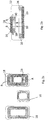
- the Figs. 1a - d show a reach truck 10 operating between a first high-bay warehouse 12 and a second high-bay warehouse 14.
- the reach truck 10 is representative of an industrial truck that is designed, for example, for a high lift.
- the reach truck 10 has an inductive charging means 16 on its underside, which interacts with an inductive charging means 18 fixed on the ground.
- Fig. 1a shows a situation in which the industrial truck 10 raises or lowers a pallet 20 in front of the shelf device 14.
- Figure 1b shows a situation in which the industrial truck 10 has moved closer to the second shelf device 14.
- the push mast 22 is in its maximally advanced position.
- Figure 1b shows how the pallet 20 is stored in the high-bay warehouse 14.
- the industrial truck 10 has moved within the aisle and relative to the inductive charging means 18.
- the reach mast 22 was pushed forward between the wheel arms.
- the comparison of the Figs. 1a and 1b clearly shows that the vehicle-mounted loading means 16 is in both positions of the vehicle, namely in the position for lifting and lowering processes Fig. 1a and in the position for storing and retrieving goods in the shelf 14, is located above the inductive charging means 18.
- Figs. 1c and 1d show the industrial truck 10 in a side facing the first shelf unit 12.
- Figure 1c shows the industrial truck 10 in a position for lifting and lowering the pallet 20 in front of the first high-bay warehouse 12. It can be clearly seen that the loading device 16 fixed to the vehicle is located above the stationary loading device 18.
- Fig. 1d shows the industrial truck 10 with the push mast 22 pushed forward when the pallet 20 is stored or removed from the first rack unit 12. It is again clear that the vehicle-mounted loading device 16 is located above the loading device 18 laid in the floor.
- Fig. 2a shows, in a schematic view, the charging means 18 laid underground, relative to the charging coil 16 that is carried along with the vehicle.
- both loading devices 16, 18 have a comparable width, but differ in the longitudinal direction. This means that the vehicle-mounted loading device 16 can move along one of the arrows A, B.
- the freedom of movement in directions A, B allows the truck to switch between a lifting and lowering position and a loading and unloading position in the aisle.
- FIG. 2b shows the schematic functionality of the inductive charging process.
- the stationary installed charging device 18 has a schematically illustrated magnetic core, which can be designed, for example, as a ferrite core or the like.
- the coil 26 is shown in section with its technical current direction.
- the vehicle-mounted loading device 16, which is also equipped with a core material 28, is located above the stationary loading device is. This vehicle-mounted loading device is also shown in cross section with its lines, the technical direction of the current being shown. Due to the same current direction in the stationary and the vehicle-mounted charging means, ring-shaped magnetic field lines 32 are formed which transfer power from the stationary charger to the vehicle-mounted charger by induction.
- Fig. 3 shows the first high rack 12 and the second high rack 14 in a schematic plan view from above.
- Each of the high racks has four vertical rack supports 34 in the corners.
- the aisle 36 with three stationary inductive charging means 18a, 18b, 18c is located between the high shelves 12, 14.
- the loading means 18 are arranged symmetrically between the high shelves 12, 14.
- a storage area 36a, 36b, 36c and 38a, 38b, 38c, respectively, are assigned to the three loading devices 18a, 18b, 18c in each high rack 12, 14.
- a distance d is provided between the storage areas.
- the distance d is also present between the outer bearing areas 38a, 38c, 36a, 36c and the carriers 34.
- the storage areas themselves have a width b which corresponds to the width B of the stationary loading means 18a, 18b, 18c.
- the width B of the stationary loading means extends in the longitudinal direction of the aisle between the shelf units 12, 14. In the longitudinal direction, the stationary loading units have a distance D from one another which is greater than the distance d between the storage areas.
- the distance A which forms the aisle width or the transverse distance between the high shelves 12 and 14, is greater than the extension a of the stationary loading means in the transverse direction between the shelves 12, 14.
- a first spacing di is provided which extends between the high-bay bay 12 and the storage unit.
- the loading unit 18a On the one from the first The side facing away from the high bay 12, the loading unit 18a has a second distance d 2 .
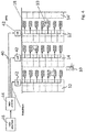
- Fig. 4 shows a high-bay warehouse 40 with its electrical connection in a schematic view.
- Various industrial trucks 10 can be seen, which transport goods between the high shelves 12, 14, 12 'and 14' and store and retrieve them.
- Stationary loading devices 18 are located between the high shelves.
- the stationary loading devices 18 in an aisle, that is to say in an area between two high-bay warehouses, are electrically supplied via a common inverter 42.
- the inverters 42 in the store 40 are fed by a common grid converter 44.
- the network converter 44 is connected to the electrical supply network 46.
- typical stacking and unstacking processes with the reach truck 10 last on average between 10 seconds and 50 seconds, depending on the height of the goods to be stacked or unstacked and the experience of the driver. During this period of time, the reach truck changes its position only slightly by driving back and forth. The change is less than 1 m. Since the height of high-bay warehouses is currently increasing on average, more goods are stored in a smaller area, the time it takes for an industrial truck to be almost stationary with inbound and outbound Outsource spends, too. However, this means that the electric charging time of the industrial truck increases in the warehouse equipped according to the invention. If one considers a high-bay warehouse in an example calculation, in which the stacking or unstacking process takes an average of 30 seconds.
Landscapes
- Engineering & Computer Science (AREA)
- Transportation (AREA)
- Structural Engineering (AREA)
- Mechanical Engineering (AREA)
- Civil Engineering (AREA)
- Life Sciences & Earth Sciences (AREA)
- Geology (AREA)
- Power Engineering (AREA)
- Chemical & Material Sciences (AREA)
- Combustion & Propulsion (AREA)
- Warehouses Or Storage Devices (AREA)
- Charge And Discharge Circuits For Batteries Or The Like (AREA)
Abstract
Description
- Die vorliegende Erfindung betrifft ein Lager mit mindestens einer Regaleinrichtung, hierbei kann es sich beispielsweise um ein Hochregallager handeln, das mit Hilfe eines oder mehrerer Flurförderzeuge bewirtschaftet wird.
- Grundsätzlich ist aus dem Stand der Technik bekannt, Flurförderzeuge induktiv zu laden. Dabei wir das Flurförderzeug über oder neben einer Ladevorrichtung abgestellt, die induktiv Energie an eine entsprechende Ladevorrichtung des Flurförderzeugs übertragen kann. Die induktive Übertragung funktioniert hierbei über Primär- und Sekundärspulen, die über einen Luftspalt hinweg elektromagnetisch gekoppelt sind. Der Vorteil des induktiven Ladens von Flurförderzeugen besteht darin, dass nicht länger ein kabelgebundenes Ladegerät eingesetzt werden muss, wodurch der Ladevorgang vereinfacht wird.
- Aus
WO 2016/014181 A1 ist bekannt, für Automobile Fahrspuren auf der Straße mit Ladevorrichtungen zum induktiven Laden während der Fahrt auszurichten. Beispielsweise kann ein Sensor vorgesehen sein, der ein heranfahrendes Automobil erkennt und entsprechend entlang der Fahrtrichtung des Autos angeordnete Ladespulen ansteuert. -
US 6,421,600 B1 betrifft vollelektrische Personenkraftwagen, die induktiv über in der Straße vorgesehene Lademittel geladen werden können. Zur Verbesserung des Ladevorgangs ist vorgesehen, ungefähr 10% der Straße mit elektrischen Lademitteln auszustatten, wobei hierzu elektrische Lademittel besonders im Bereich vom Kreuzungen und Ampeln vorgesehen werden. - Aus
DE 10 2017 107 309 A1 ist ein Energiemanagement für ein Container-Terminal bekannt, bei dem elektrifizierte Krane für das Handling der Container eingesetzt werden. Die Krane operieren unabhängig voneinander, so dass bei deren gleichzeitigen Betrieb Netzspannungen und Rückwirkungen für das Netz auftreten können. Es wird daher vorgeschlagen, einen Energiespeicher für die elektrischen Krane vorzusehen, der mit günstigem Strom geladen wird und Netzspannungsschwankungen verhindert. - Im Bereich der Logistik besteht das Bedürfnis, Lager mit Regaleinheiten bereitzustellen, die für induktiv ladbare Flurförderzeuge einen effektiven Betrieb gewährleisten.
- Erfindungsgemäß wird die Aufgabe durch ein Lager mit den Merkmalen von Anspruch 1 gelöst. Vorteilhafte Ausgestaltungen bilden die Gegenstände der Unteransprüche.
- Das erfindungsgemäße Lager ist mit mindestens einer Regaleinrichtung ausgestattet, in die mit einem Flurförderzeug Lasten eingelagert und aus der mit dem Flurförderzeug Lasten ausgelagert werden können. Bei der Regaleinrichtung kann es sich beispielsweise um ein Hochregallager handeln. Das erfindungsgemäße Lager besitzt zudem einen entlang der Regaleinrichtung verlaufenden Gang. Erfindungsgemäß ist ein induktives Lademittel für das Flurförderzeug in dem Gang vorgesehen. Das induktive Lademittel ist vorgesehen, um ein sich in der Nähe des Lademittels befindliches Flurförderzeug induktiv zu laden. Das induktive Lademittel besitzt an seiner zu der Regaleinrichtung weisenden Seite einen ersten Abstand und seiner von der Regaleinrichtung fortweisenden Seite einen zweiten Abstand zu der Regaleinrichtung. Die Differenz dieser beiden Abstände bildet dabei die Quererstreckung des induktiven Lademittels. Erfindungsgemäß ist der erste Abstand so bemessen, dass das Flurförderzeug bei einem Ein- und Auslagervorgang induktiv geladen werden kann. Bei einem Ein- und Ausladevorgang fährt das Flurförderzeug nah an die Regaleinrichtung heran, um die Last aus dem Lager herausnehmen zu können oder in dieser absetzen zu können. Das induktive Lademittel erstreckt sich nun so nah an die Regaleinrichtung heran, dass das Flurförderzeug auch bei seinen Lagervorgängen noch induktiv geladen werden kann.
- Der zweite Abstand ist erfindungsgemäß so bemessen, dass das Flurförderzeug auch bei einem Hebe- und Senkvorgang induktiv geladen werden kann. Bei dem Hebe- und Senkvorgang besitzt das Flurförderzeug einen Abstand zur Regaleinrichtung. Dieser Abstand erlaubt es, die aus der Regaleinheit entnommene Last abzusenken oder eine in die Regaleinheit einzulagernde Last anzuheben. Die erfindungsgemäße Dimensionierung des induktiven Lademittels relativ zu der Regaleinrichtung erlaubt es somit, das Flurförderzeug sowohl bei Ein- und Auslagervorgängen induktiv zu laden als auch während der Zeit, in der die Last angehoben und abgesenkt wird, das Flurförderzeug induktiv zu laden. Das mit einem solchen induktiven Lademittel ausgestattete Lager besitzt eine große Anzahl von technischen Vorteilen. Zunächst kann auf eine an sich bekannte stationäre induktive Ladetechnik zurückgegriffen werden, wobei das eingesetzte induktive Lademittel dabei entsprechend dimensioniert werden muss, um einen Ladevorgang sowohl während des Ein- und Auslagerns als auch während des Hebens und Senkens vor der Regaleinrichtung sicherzustellen. Zudem kann der hohe Wirkungsgrad des induktiven Ladevorgangs auch hier genutzt werden. Weiterhin erweist es sich als sehr vorteilhaft, dass der Ladevorgang auch gerade während der Hubvorgänge erfolgt. Hierbei wird das Flurförderzeug elektrisch stark belastet, so dass eine zusätzliche Energieversorgung über den induktiven Ladevorgang hier sehr vorteilhaft ist.
- In einer bevorzugten Weiterbildung des erfindungsgemäßen Lagers sind zwei Lagereinrichtungen vorgesehen, die einander gegenüberliegend den Gang begrenzen, wobei das Lademittel mit seiner zu einer ersten Regaleinrichtung weisenden Seite den ersten Abstand und mit seiner zu der zweiten Regaleinrichtung weisenden Seite einen dritten Abstand aufweist. Der dritte Abstand ist dabei so bemessen, dass das Flurförderzeug bei einem Ein- und Auslagervorgang in die zweite Regaleinrichtung induktiv geladen werden kann, wobei der erste Abstand so klein bemessen ist, dass das Flurförderzeug bei einem Hebe- und Senkvorgang vor der zweiten Regaleinrichtung induktiv geladen werden kann. Bei den vorstehend definierten Abständen ergibt sich die Gangbreite zwischen erster und zweiter Regaleinrichtung als die Summe aus zweitem und drittem Abstand. Grundsätzlich müssen erster und dritter Abstand nicht gleich groß sein, bevorzugt können diese jedoch bei im Wesentlichen gleich aufgebauten Regaleinrichtungen auch gleiche Abmessungen besitzen, so dass das Lademittel mittig zwischen den Regaleinrichtungen angeordnet werden kann.
- In einer weiter fortgebildeten Ausgestaltung besitzt das Lager entlang eines Ganges eine Vielzahl von induktiven Lademitteln. Die Lademittel sind dabei bevorzugt so in dem Gang verteilt, dass diese entlang der Längsrichtung des Ganges einzelnen Stellbereichen der Regaleinrichtung zugeordnet sind. Dabei ist es nicht erforderlich, dass jedem Stellbereich im Lager auch notwendig ein induktives Lademittel zugeordnet ist.
- In einer bevorzugten Weiterbildung wird die Vielzahl der induktiven Lademittel in einem Gang von einem Wechselrichter gemeinsam gespeist. Dies bedeutet, in dem Lager ist bevorzugt ein Wechselrichter pro Gang vorgesehen, wobei der Gang mehrere in Längsrichtung des Ganges hintereinander angeordnete induktive Lademittel aufweist. Bevorzugt wird eines der induktiven Lademittel von dem Wechselrichter zum Laden eines auf dem induktiven Lademittel sich befindenden Flurförderzeugs angesteuert.
- Das erfindungsgemäße Lager weist mehrere Gänge auf, die jeweils eine Vielzahl von induktiven Lademitteln mit einem Wechselrichter aufweisen. Es befinden sich also mehrere Wechselrichter in dem Lager. Bevorzugt werden die mehreren Wechselrichter von einem gemeinsamen Netzumrichter gespeist, der über einen Netzanschluss mit dem elektrischen Versorgungsnetz verbunden ist.
- In einer bevorzugten Ausgestaltung sind in dem Gang das oder die induktiven Lademittel jeweils einem Lagerplatz zugeordnet. Ein Lagerplatz ist hierbei ein zum Ein- und Ausladen von Lasten vorgesehener Bereich der Regaleinrichtung.
- In einer bevorzugten Ausgestaltung ist eine übergeordnete Steuerung für die Lagerplätze vorgesehen, die dazu ausgebildet ist, einen mit einem induktiven Lademittel ausgestatteten Lagerplatz stärker zu frequentieren als einen nicht mit einem induktiven Lademittel ausgebildeten Lagerplatz. Die übergeordnete Steuerung, beispielsweise ein Waren-Management-System, ist vorgesehen, um den eingelagerten Waren und Gütern in der Regaleinrichtung einen Platz zuzuweisen. Dabei ist die übergeordnete Steuerung bevorzugt derart ausgebildet, dass die Plätze nicht gleichmäßig über die Regaleinrichtung verteilt sind, sondern stärker frequentierte Lagerplätze geschaffen werden, an denen sich die in dem Lager eingesetzten Flurförderzeuge häufig befinden, um Waren ein- und auszulagern. Als solche Lagerplätze werden bevorzugt Lagerplätze mit induktiven Lademitteln ausgewählt. Bevorzugt sind in Ganglängsrichtung Bereiche zwischen Lagerplätzen frei von induktiven Lademitteln.
- In einer bevorzugten Weiterbildung des Lagers ist mindestens ein Flurförderzeug mit einem induktiven Lademittel vorgesehen, das ausgebildet ist, um auch während des Betriebs die Batterie induktiv zu laden.
- Die Erfindung wird an dem nachfolgenden Ausführungsbeispiel näher erläutert. Es zeigen:
- Fign. 1a-d
- die Arbeitsweise eines Flurförderzeugs in einem beidseitig durch Regale begrenzten Gang,
- Fign. 2a - b
- induktive Lademittel für den Gang sowie für das Flurförderzeug und deren Wirkweise,
- Fig. 3
- eine Draufsicht auf ein Hochregallager mit entsprechenden Bodenspulen im Gang und
- Fig. 4
- eine Gesamtansicht eines Lagers mit mehreren Gängen und Wechselrichter.
- Die
Fign. 1a - d zeigen einen Schubmaststapler 10, der zwischen einem ersten Hochregallager 12 und einem zweiten Hochregallager 14 operiert. Der Schubmaststapler 10 steht in dem Ausführungsbeispiel stellvertretend für ein Flurförderzeug, das beispielsweise für einen Hochhub ausgebildet ist. Der Schubmaststapler 10 besitzt auf seiner Unterseite ein induktives Lademittel 16, das mit einem untergrundfesten induktiven Lademittel 18 zusammenwirkt.Fig. 1a zeigt eine Situation, in der das Flurförderzeug 10 eine Palette 20 vor der Regaleinrichtung 14 anhebt oder senkt.Fig. 1b zeigt eine Situation, in der das Flurförderzeug 10 näher an die zweite Regaleinrichtung 14 herangefahren ist. Zudem ist der Schubmast 22 in seiner maximal vorgeschobenen Position.Fig. 1b zeigt, wie die Palette 20 in das Hochregallager 14 eingelagert wird. Das Flurförderzeug 10 hat sich dazu innerhalb des Gangs und relativ zu dem induktiven Lademittel 18 bewegt. Zudem wurde der Schubmast 22 zwischen den Radarmen vorgeschoben. Der Vergleich derFign. 1a und 1b zeigt bereits deutlich, dass das fahrzeugfeste Lademittel 16 sich in beiden Positionen des Fahrzeugs, nämlich in der Position für Hub- und Senkvorgänge ausFig. 1a und in der Position zum Ein- und Auslagern von Waren in das Regal 14, sich oberhalb des induktiven Lademittels 18 befindet. -
Fign. 1c und 1d zeigen das Flurförderzeug 10 in einer zu der ersten Regaleinheit 12 weisenden Seite.Fig. 1c zeigt das Flurförderzeug 10 in einer Position zum Heben und Senken der Palette 20 vor dem ersten Hochregallager 12. Deutlich zu erkennen ist, dass die fahrzeugfeste Ladeeinrichtung 16 sich oberhalb der ortsfesten Ladeeinrichtung 18 befindet.Fig. 1d zeigt das Flurförderzeug 10 mit vorgeschobenem Schubmast 22 beim Ein- oder Auslagern der Palette 20 in der ersten Regaleinheit 12. Wieder wird deutlich, dass sich das fahrzeugfeste Lademittel 16 oberhalb des im Boden verlegten Lademittels 18 befindet. -
Fig. 2a zeigt in einer schematischen Ansicht, das im Untergrund verlegte Lademittel 18, relativ zu der fahrzeugfest mitgeführten Ladespule 16. InFig. 2a ist zu erkennen, dass beide Lademittel 16, 18 eine vergleichbare Breite besitzen, sich jedoch in der Längsrichtung unterscheiden. Dies bedeutet, dass das fahrzeugfeste Lademittel 16 sich entlang einem der Pfeile A, B bewegen kann. Die Bewegungsfreiheit in den Richtungen A, B erlaubt es dem Flurförderzeug im Gang zwischen einer Hebe- und Senkenposition sowie einer Ein- und Auslageposition zu wechseln. -
Fig. 2b zeigt die schematische Funktionsweise des induktiven Ladevorgangs. Die ortsfest verlegte Ladeeinrichtung 18 besitzt einen schematisch dargestellten magnetischen Kern, der beispielsweise als ein Ferrit-Kern oder dergleichen ausgebildet sein kann. Zudem ist im Schnitt die Spule 26 mit ihrer technischen Stromrichtung dargestellt. Oberhalb des ortsfesten Lademittels befindet sich das fahrzeugfeste Lademittel 16, das ebenfalls mit einem Kernmaterial 28 ausgestattet ist. Auch dieses fahrzeugfeste Lademittel ist im Querschnitt mit seinen Leitungen dargestellt, wobei die technische Stromrichtung eingezeichnet ist. Aufgrund der gleichen Stromrichtung in dem ortsfesten und dem fahrzeugfesten Lademittel bilden sich ringförmige Magnetfeldlinien 32 aus, die per Induktion Leistung von dem ortsfesten Ladegerät zu dem fahrzeugfesten Ladegerät übertragen. -
Fig. 3 zeigt in einer schematischen Draufsicht von oben das erste Hochregal 12 und das zweite Hochregal 14. Jedes der Hochregale besitzt vier senkrecht stehende Regalträger 34 in den Ecken. Zwischen den Hochregalen 12, 14 befindet sich der Gang 36 mit drei ortsfesten induktiven Lademitteln 18a, 18b, 18c. In dem Ausführungsbeispiel ausFig. 3 sind die Lademittel 18 symmetrisch zwischen den Hochregalen 12, 14 angeordnet. - Den drei Lademitteln 18a, 18b, 18c zugeordnet sind in jedem Hochregal 12, 14 jeweils ein Lagerbereich 36a, 36b, 36c bzw. 38a, 38b, 38c. Zwischen den Lagerbereichen ist jeweils ein Abstand d vorgesehen. Der Abstand d liegt auch zwischen den äußeren Lagerbereichen 38a, 38c, 36a, 36c und den Trägern 34 vor. Die Lagerbereiche selbst besitzen eine Breite b, die der Breite B der ortsfesten Lademittel 18a, 18b, 18c entspricht. Die Breite B der ortsfesten Lademittel erstreckt sich in Längsrichtung des Ganges zwischen den Regaleinheiten 12, 14. In Längsrichtung besitzen die ortsfesten Ladeeinheiten einen Abstand D voneinander, der größer als der Abstand d zwischen den Lagerbereichen ist. Der Abstand A, der die Gangbreite bzw. den Querabstand zwischen den Hochregalen 12 und 14 bildet, ist größer als die Erstreckung a der ortsfesten Lademittel in Querrichtung zwischen den Regalen 12, 14.
- Bezogen auf das erste Hochregallager ist ein erster Abstand di vorgesehen, der sich zwischen dem Hochregal 12 und der Lagereinheit erstreckt. Auf der von dem ersten Hochregal 12 fortweisenden Seite besitzt die Ladeeinheit 18a einen zweiten Abstand d2. Bezogen auf das zweite Hochregal 14 besitzt die Ladeeinheit 18a einen dritten Abstand d3. Es ist leicht einzusehen, dass in dem dargestellten Ausführungsbeispiel mit symmetrisch angeordneten Lademitteln der Abstand d1 dem Abstand d3 entspricht. Auch folgt unmittelbar, dass die Summe aus Abstand d2 und d3 gerade der Gangbreite A entspricht. Ferner gilt im symmetrischen Fall, dass d1 + a = d3 + a = d2 ist, sich also die kurzen Abstände zu den Regaleinheiten um die Längserstreckung des ortsfesten Lademittels von dem längeren Abstandswert d2 unterscheiden.
-
Fig. 4 zeigt ein Hochregallager 40 mit seiner elektrischen Verbindung in einer schematischen Ansicht. Zu erkennen sind verschiedene Flurförderzeuge 10, die zwischen den Hochregalen 12, 14, 12' und 14' Waren transportieren und diese ein- bzw. auslagern. Zwischen den Hochregalen befinden sich stationäre Lademittel 18. Die stationären Lademittel 18 in einem Gang, also in einem Bereich zwischen zwei Hochregallagern werden über einen gemeinsamen Wechselrichter 42 elektrisch versorgt. Die Wechselrichter 42 in dem Lager 40 werden von einem gemeinsamen Netzumrichter 44 gespeist. Der Netzumrichter 44 ist an das elektrische Versorgungsnetz 46 angeschlossen. - In dem erfindungsgemäßen Regallager 40 dauern typische Ein- und Ausstapelvorgänge mit dem Schubmaststapler 10 durchschnittlich zwischen 10 Sekunden und 50 Sekunden, je nach Höhe der ein- oder auszustapelnden Ware und der Erfahrung des Fahrers. Während dieser Zeitspanne ändert der Schubmaststapler seine Position lediglich geringfügig durch ein Vor- und Zurückfahren. Die Veränderung ist dabei weniger als 1 m. Da zudem die Höhe von Hochregallagern gegenwärtig durchschnittlich zunimmt, es werden mehr Waren auf kleinerer Fläche gelagert, nimmt die Zeit, die ein Flurförderzeug fast stationär mit Ein- und Auslagern verbringt, zu. Dies bedeutet aber, dass bei dem erfindungsgemäß ausgestatteten Lager die elektrische Ladezeit des Flurförderzeugs zunimmt. Betrachtet man in einer Beispielrechnung ein Hochregallager, bei dem der Ein- oder Ausstapelvorgang durchschnittlich 30 Sekunden dauert. Bei 100 Ein-/Ausstapelvorgängen pro 8 Stundenschicht ergibt sich eine Zeitspanne von 50 Minuten pro Schicht, die zum Laden des Flurförderzeugs zur Verfügung steht. Erfolgt eine induktive Ladung des Schubmaststaplers mit 10 kW Leistung, bedeutet dies, eine Lademenge von 8,3 kWh pro Schicht. Liegt der typische Energieverbrauch des Schubmaststaplers in einer 8-Stunden-Schicht bei ca. 10 kWh, so können 83,3 % der Energie über das induktive Laden zur Verfügung gestellt werden. Mittels des erfindungsgemäßen induktiven Lademittels kann also statistisch gesehen der überwiegende Teil der für den Betrieb von Flurförderzeugen benötigten Energie während der anfallenden Ein- und Ausstapelvorgänge nachgeladen werden. Standzeiten des Flurförderzeugs am Ladegerät können hierdurch signifikant reduziert werden. Gleiches gilt für die Kapazität der im Flurförderzeug verbauten Batterie, da während des Betriebs des Flurförderzeugs regelmäßig nachgeladen wird.
-
- 10
- Flurförderzeug
- 12
- Hochregallager
- 12'
- Hochregallager
- 14
- Hochregallager
- 14'
- Hochregallager
- 16
- induktives Lademittel
- 18
- induktives Lademittel
- 18a-c
- Lademittel
- 20
- Palette
- 22
- Schubmast
- 26
- Spule
- 28
- Ferrit-Material
- 32
- Magnetfeldlinien
- 34
- Träger
- 36
- Gang
- 36a-c
- Lagerbereich
- 38a-c
- Lagerbereich
- 40
- Lager
- 42
- Wechselrichter
- 44
- Netzumrichter
- 46
- Versorgungsnetz
Claims (11)
- Lager mit mindestens einer Regaleinrichtung (12, 14), in die mit einem Flurförderzeug (10) Lasten ein- und aus der Lasten ausgelagert werden können, und mit einem entlang der Regaleinrichtung verlaufenden Gang (36), dadurch gekennzeichnet, dass ein induktives Lademittel (16, 18) für das in dem Gang (36) befindliche Flurförderzeug (10) vorgesehen ist, wobei das induktive Lademittel (16, 18) an seiner zu der Regaleinrichtung weisenden Seite einen ersten Abstand (d1) und an seiner von der Regaleinrichtung fortweisenden Seite einen zweiten Abstand (d2) zu der Regaleinrichtung aufweist, wobei der erste Abstand (d1) so bemessen ist, dass das Flurförderzeug (10) bei einem Ein- und Auslagervorgang induktiv geladen werden kann und der zweite Abstand (d2) so bemessen ist, dass das Flurförderzeug (10) auch bei einem Hebe- und Senkvorgang induktiv geladen werden kann.
- Lager nach Anspruch 1, dadurch gekennzeichnet, dass zwei Regaleinrichtungen (12, 14) vorgesehen sind, die einander gegenüberliegend den Gang (36) begrenzen, wobei das induktive Lademittel (16, 18) mit seiner zu einer ersten Regaleinrichtung (12) weisenden Seite den ersten Abstand aufweist und mit seiner zu der zweiten Regaleinrichtung (14) weisenden Seite einen dritten Abstand (d3) aufweist, wobei der dritte Abstand (d3) so bemessen ist, dass das Flurförderzeug (10) bei einem Ein- und Auslagervorgang in die zweite Regaleinrichtung (14) induktiv geladen werden und der erste Abstand (d1) so klein bemessen ist, dass das Flurförderzeug (10) auch bei einem Heben- oder Senkvorgang vor der zweiten Regaleinrichtung (14) induktiv geladen werden kann.
- Lager nach Anspruch 1 oder 2, dadurch gekennzeichnet, dass eine Vielzahl von induktiven Lademitteln (16, 18) entlang dem Gang (36) angeordnet ist.
- Lager nach einem der Ansprüche 1 bis 3, dadurch gekennzeichnet, dass die Vielzahl der induktiven Lademittel (16, 18) von einem Wechselrichter (42) gemeinsam gespeist wird.
- Lager nach Anspruch 4, dadurch gekennzeichnet, dass eines der induktiven Lademittel (16, 18) von dem Wechselrichter (42) zum Laden eines auf dem induktiven Lademittel (16, 18) sich befindenden Flurförderzeugs (10) angesteuert werden.
- Lager nach einem der Ansprüche 1 bis 5, dadurch gekennzeichnet, dass das mehrere Gänge (36a-c) in dem Lager vorgesehen sind, die jeweils eine Vielzahl von induktiven Lademitteln (16, 18) mit einem Wechselrichter (42) aufweisen.
- Lager nach Anspruch 6, dadurch gekennzeichnet, dass die Wechselrichter (42) der mehreren Gänge (36a-c) von einem gemeinsamen Netzumrichter (44) gespeist werden, der über einen Netzanschluss mit dem elektrischen Versorgungsnetz (46) verbunden ist.
- Lager nach einem der Ansprüche 1 bis 7, dadurch gekennzeichnet, dass in dem Gang (36) das oder die induktiven Lademittel (16, 18) einem Lagerplatz zugeordnet sind.
- Lager nach Anspruch 8, dadurch gekennzeichnet, dass zwischen Lagerplätzen Gangbereiche vorgesehen sind, die frei von induktiven Lademitteln sind.
- Lager nach einem der Ansprüche 1 bis 9, dadurch gekennzeichnet, dass eine übergeordnete Steuerung für die Lagerplätze dazu ausgebildet ist, einen mit einer induktiven Ladeeinheit (16, 18) ausgestatteten Lagerplatz stärker zu frequentieren als einen nicht mit einer induktiven Ladeeinheit ausgebildeten Lagerplatz.
- Lager nach einem der Ansprüche 1 bis 10, dadurch gekennzeichnet, dass mindestens ein Flurförderzeug (10) vorgesehen ist, das mit einer induktiven Ladeeinrichtung (16, 18) ausgestattet ist, über die eine Batterie des Fahrzeugs auch während des Betriebs geladen werden kann.
Applications Claiming Priority (1)
| Application Number | Priority Date | Filing Date | Title |
|---|---|---|---|
| DE102019131365.1A DE102019131365A1 (de) | 2019-11-20 | 2019-11-20 | Lager mit mindestens einer Regaleinrichtung |
Publications (2)
| Publication Number | Publication Date |
|---|---|
| EP3825163A1 true EP3825163A1 (de) | 2021-05-26 |
| EP3825163B1 EP3825163B1 (de) | 2025-12-03 |
Family
ID=72717685
Family Applications (1)
| Application Number | Title | Priority Date | Filing Date |
|---|---|---|---|
| EP20199494.4A Active EP3825163B1 (de) | 2019-11-20 | 2020-10-01 | Lager mit mindestens einer regaleinrichtung |
Country Status (2)
| Country | Link |
|---|---|
| EP (1) | EP3825163B1 (de) |
| DE (1) | DE102019131365A1 (de) |
Cited By (1)
| Publication number | Priority date | Publication date | Assignee | Title |
|---|---|---|---|---|
| EP3862212A1 (de) * | 2020-02-06 | 2021-08-11 | Jungheinrich Aktiengesellschaft | Verfahren zum anordnen von induktiven lademitteln in einem lager sowie lager mit einer anordnung von induktiven lademitteln sowie flurförderzeug für ein solches lager |
Families Citing this family (4)
| Publication number | Priority date | Publication date | Assignee | Title |
|---|---|---|---|---|
| DE102021109363A1 (de) | 2021-04-14 | 2022-10-20 | Jungheinrich Aktiengesellschaft | Induktives Ladesystem für Flurförderzeuge |
| CN113548354B (zh) * | 2021-06-23 | 2023-02-24 | 郑州铁路职业技术学院 | 一种智能物流储存系统 |
| EP4461587A1 (de) * | 2023-05-12 | 2024-11-13 | Jungheinrich Aktiengesellschaft | Flurförderzeug mit einer fahrerstandplattform |
| DE102024124775A1 (de) | 2024-08-29 | 2026-03-05 | Conductix-Wampfler Gmbh | Kontaktelement, Stromabnehmer, Kontaktstation, Kontaktladesystem und Anlage |
Citations (8)
| Publication number | Priority date | Publication date | Assignee | Title |
|---|---|---|---|---|
| US6421600B1 (en) | 1994-05-05 | 2002-07-16 | H. R. Ross Industries, Inc. | Roadway-powered electric vehicle system having automatic guidance and demand-based dispatch features |
| WO2005002998A1 (de) * | 2003-07-01 | 2005-01-13 | Sew-Eurodrive Gmbh & Co. Kg | Spurgeführtes transportsystem |
| WO2011089063A1 (de) * | 2010-01-22 | 2011-07-28 | Koruna-Lc S.R.O. | Hochregallager zur lagerung von paletten, regalbediengerät, tandemshuttle, übergaberegal sowie verfahren zur lagerung von paletten in dem hochregallager |
| WO2012083062A1 (en) * | 2010-12-15 | 2012-06-21 | Casepick Systems, Llc | Device for building a group of goods units for storage |
| WO2016014181A1 (en) | 2014-07-25 | 2016-01-28 | Qualcomm Incorporated | Devices, systems, and method for dynamic electric vehicle charging with position detection |
| WO2016137540A1 (en) * | 2015-02-26 | 2016-09-01 | Cascade Corporation | Devices and methods for inductive power transfer and power control for industrial equipment |
| DE102015122902A1 (de) * | 2015-12-29 | 2017-06-29 | Still Gmbh | System aus Batterieladevorrichtung und Flurförderzeugen |
| DE102017107309A1 (de) | 2017-04-05 | 2018-10-11 | Paul Vahle Gmbh & Co. Kg | Energiemanagement für ein Containerterminal |
Family Cites Families (3)
| Publication number | Priority date | Publication date | Assignee | Title |
|---|---|---|---|---|
| US7931431B2 (en) * | 2003-05-06 | 2011-04-26 | Bec Companies, Inc. | Automated material handling system with load transfer vehicles |
| DE102009007954A1 (de) * | 2009-02-06 | 2010-08-19 | Sew-Eurodrive Gmbh & Co. Kg | Verfahren und Vorrichtung zur Wegsteuerung eines Fahrzeuges |
| DE102012025154B4 (de) * | 2012-12-21 | 2021-07-22 | Sew-Eurodrive Gmbh & Co Kg | Lager, insbesondere Lageranordnung, insbesondere Lager für Container |
-
2019
- 2019-11-20 DE DE102019131365.1A patent/DE102019131365A1/de active Pending
-
2020
- 2020-10-01 EP EP20199494.4A patent/EP3825163B1/de active Active
Patent Citations (8)
| Publication number | Priority date | Publication date | Assignee | Title |
|---|---|---|---|---|
| US6421600B1 (en) | 1994-05-05 | 2002-07-16 | H. R. Ross Industries, Inc. | Roadway-powered electric vehicle system having automatic guidance and demand-based dispatch features |
| WO2005002998A1 (de) * | 2003-07-01 | 2005-01-13 | Sew-Eurodrive Gmbh & Co. Kg | Spurgeführtes transportsystem |
| WO2011089063A1 (de) * | 2010-01-22 | 2011-07-28 | Koruna-Lc S.R.O. | Hochregallager zur lagerung von paletten, regalbediengerät, tandemshuttle, übergaberegal sowie verfahren zur lagerung von paletten in dem hochregallager |
| WO2012083062A1 (en) * | 2010-12-15 | 2012-06-21 | Casepick Systems, Llc | Device for building a group of goods units for storage |
| WO2016014181A1 (en) | 2014-07-25 | 2016-01-28 | Qualcomm Incorporated | Devices, systems, and method for dynamic electric vehicle charging with position detection |
| WO2016137540A1 (en) * | 2015-02-26 | 2016-09-01 | Cascade Corporation | Devices and methods for inductive power transfer and power control for industrial equipment |
| DE102015122902A1 (de) * | 2015-12-29 | 2017-06-29 | Still Gmbh | System aus Batterieladevorrichtung und Flurförderzeugen |
| DE102017107309A1 (de) | 2017-04-05 | 2018-10-11 | Paul Vahle Gmbh & Co. Kg | Energiemanagement für ein Containerterminal |
Cited By (2)
| Publication number | Priority date | Publication date | Assignee | Title |
|---|---|---|---|---|
| EP3862212A1 (de) * | 2020-02-06 | 2021-08-11 | Jungheinrich Aktiengesellschaft | Verfahren zum anordnen von induktiven lademitteln in einem lager sowie lager mit einer anordnung von induktiven lademitteln sowie flurförderzeug für ein solches lager |
| US12214680B2 (en) | 2020-02-06 | 2025-02-04 | Jungheinrich Aktiengesellschaft | Method for arranging inductive chargers in a warehouse, system having an arrangement of inductive chargers, and an industrial truck for a warehouse |
Also Published As
| Publication number | Publication date |
|---|---|
| DE102019131365A1 (de) | 2021-05-20 |
| EP3825163B1 (de) | 2025-12-03 |
Similar Documents
| Publication | Publication Date | Title |
|---|---|---|
| EP3825163B1 (de) | Lager mit mindestens einer regaleinrichtung | |
| EP1254852B1 (de) | Lager- und Transportsystem in modularer Bauweise | |
| EP2607292B1 (de) | System zum Transport von auf Hilfsmitteln angeordneten Gütern | |
| EP2935052B1 (de) | Lager, insbesondere lageranordnung, insbesondere lager für container | |
| EP2440488B1 (de) | System zum wechseln einer batterie eines flurgebundenen transportfahrzeuges, insbesondere eines fahrerlosen schwerlast-transportfahrzeuges für iso-container | |
| EP3183190B1 (de) | Lager- und/oder kommissioniersysteme | |
| EP3277519B1 (de) | Lagersystem mit einem omnidirektionalen fahrzeug und verfahren zum betreiben eines solchen lagersystems | |
| DE102014003451A1 (de) | Reagalbediengerät mit hochgesetzter Fahrschiene | |
| EP2062837A1 (de) | Verfahren zum Betreiben einer Flurförderanlage und Flurförderanlage | |
| AT514710A1 (de) | Automatisches Regallagersystem mit unabhängig voneinander verfahrbaren Förderfahrzeugen, sowie Verfahren hierzu | |
| WO2011089063A1 (de) | Hochregallager zur lagerung von paletten, regalbediengerät, tandemshuttle, übergaberegal sowie verfahren zur lagerung von paletten in dem hochregallager | |
| DE102009051800A1 (de) | Lageranordnung | |
| EP3704040A1 (de) | Regalsystem mit shuttlefahrzeug | |
| EP3523221A1 (de) | Regalbediengerät und regallagersystem mit verbesserter zugänglichkeit und gewichtsverteilung | |
| EP1644274B1 (de) | Spurgeführtes transportsystem | |
| EP1763449A1 (de) | Spurgeführtes transportsystem | |
| DE102004045517A1 (de) | System mit stationären und mobilen Funktionseinrichtungen | |
| DE102014206590A1 (de) | Logistiksystem und Verfahren zur Übergabe und/oder Übernahme von Waren zwischen einem Fahrzeug und einem Warenlager | |
| EP3527507A2 (de) | Kommissioniereinrichtung und kommissionierwagen für ein wabenlager | |
| EP3924291B1 (de) | Fördereinrichtung für ladungsträger | |
| DE102021002699A1 (de) | Regalanordnung für ein Lagersystem und Lagersystem | |
| DE3631602A1 (de) | Regalanordnung | |
| DE102020122084B3 (de) | Betriebsstrategie für ein Regallager mit Regalbediengeräten | |
| EP3862212B1 (de) | Verfahren zum anordnen von induktiven lademitteln in einem lager sowie lager mit einer anordnung von induktiven lademitteln sowie flurförderzeug für ein solches lager | |
| DE2239126A1 (de) | Palettenwagen, insbesondere zur be- bzw. entladung eines hochregallagers |
Legal Events
| Date | Code | Title | Description |
|---|---|---|---|
| PUAI | Public reference made under article 153(3) epc to a published international application that has entered the european phase |
Free format text: ORIGINAL CODE: 0009012 |
|
| STAA | Information on the status of an ep patent application or granted ep patent |
Free format text: STATUS: THE APPLICATION HAS BEEN PUBLISHED |
|
| AK | Designated contracting states |
Kind code of ref document: A1 Designated state(s): AL AT BE BG CH CY CZ DE DK EE ES FI FR GB GR HR HU IE IS IT LI LT LU LV MC MK MT NL NO PL PT RO RS SE SI SK SM TR |
|
| STAA | Information on the status of an ep patent application or granted ep patent |
Free format text: STATUS: REQUEST FOR EXAMINATION WAS MADE |
|
| 17P | Request for examination filed |
Effective date: 20211116 |
|
| RBV | Designated contracting states (corrected) |
Designated state(s): AL AT BE BG CH CY CZ DE DK EE ES FI FR GB GR HR HU IE IS IT LI LT LU LV MC MK MT NL NO PL PT RO RS SE SI SK SM TR |
|
| STAA | Information on the status of an ep patent application or granted ep patent |
Free format text: STATUS: EXAMINATION IS IN PROGRESS |
|
| 17Q | First examination report despatched |
Effective date: 20220823 |
|
| P01 | Opt-out of the competence of the unified patent court (upc) registered |
Effective date: 20230628 |
|
| GRAP | Despatch of communication of intention to grant a patent |
Free format text: ORIGINAL CODE: EPIDOSNIGR1 |
|
| GRAJ | Information related to disapproval of communication of intention to grant by the applicant or resumption of examination proceedings by the epo deleted |
Free format text: ORIGINAL CODE: EPIDOSDIGR1 |
|
| GRAP | Despatch of communication of intention to grant a patent |
Free format text: ORIGINAL CODE: EPIDOSNIGR1 |
|
| STAA | Information on the status of an ep patent application or granted ep patent |
Free format text: STATUS: GRANT OF PATENT IS INTENDED |
|
| INTG | Intention to grant announced |
Effective date: 20250428 |
|
| GRAJ | Information related to disapproval of communication of intention to grant by the applicant or resumption of examination proceedings by the epo deleted |
Free format text: ORIGINAL CODE: EPIDOSDIGR1 |
|
| STAA | Information on the status of an ep patent application or granted ep patent |
Free format text: STATUS: EXAMINATION IS IN PROGRESS |
|
| GRAP | Despatch of communication of intention to grant a patent |
Free format text: ORIGINAL CODE: EPIDOSNIGR1 |
|
| STAA | Information on the status of an ep patent application or granted ep patent |
Free format text: STATUS: GRANT OF PATENT IS INTENDED |
|
| INTC | Intention to grant announced (deleted) | ||
| GRAJ | Information related to disapproval of communication of intention to grant by the applicant or resumption of examination proceedings by the epo deleted |
Free format text: ORIGINAL CODE: EPIDOSDIGR1 |
|
| STAA | Information on the status of an ep patent application or granted ep patent |
Free format text: STATUS: EXAMINATION IS IN PROGRESS |
|
| INTG | Intention to grant announced |
Effective date: 20250722 |
|
| GRAP | Despatch of communication of intention to grant a patent |
Free format text: ORIGINAL CODE: EPIDOSNIGR1 |
|
| STAA | Information on the status of an ep patent application or granted ep patent |
Free format text: STATUS: GRANT OF PATENT IS INTENDED |
|
| INTC | Intention to grant announced (deleted) | ||
| GRAS | Grant fee paid |
Free format text: ORIGINAL CODE: EPIDOSNIGR3 |
|
| INTG | Intention to grant announced |
Effective date: 20250918 |
|
| GRAA | (expected) grant |
Free format text: ORIGINAL CODE: 0009210 |
|
| STAA | Information on the status of an ep patent application or granted ep patent |
Free format text: STATUS: THE PATENT HAS BEEN GRANTED |
|
| AK | Designated contracting states |
Kind code of ref document: B1 Designated state(s): AL AT BE BG CH CY CZ DE DK EE ES FI FR GB GR HR HU IE IS IT LI LT LU LV MC MK MT NL NO PL PT RO RS SE SI SK SM TR |
|
| REG | Reference to a national code |
Ref country code: CH Ref legal event code: F10 Free format text: ST27 STATUS EVENT CODE: U-0-0-F10-F00 (AS PROVIDED BY THE NATIONAL OFFICE) Effective date: 20251203 Ref country code: GB Ref legal event code: FG4D Free format text: NOT ENGLISH |
|
| REG | Reference to a national code |
Ref country code: DE Ref legal event code: R096 Ref document number: 502020012323 Country of ref document: DE |
|
| REG | Reference to a national code |
Ref country code: IE Ref legal event code: FG4D Free format text: LANGUAGE OF EP DOCUMENT: GERMAN |
|
| REG | Reference to a national code |
Ref country code: NL Ref legal event code: MP Effective date: 20251203 |
|
| PG25 | Lapsed in a contracting state [announced via postgrant information from national office to epo] |
Ref country code: ES Free format text: LAPSE BECAUSE OF FAILURE TO SUBMIT A TRANSLATION OF THE DESCRIPTION OR TO PAY THE FEE WITHIN THE PRESCRIBED TIME-LIMIT Effective date: 20251203 |
|
| REG | Reference to a national code |
Ref country code: LT Ref legal event code: MG9D |
|
| PG25 | Lapsed in a contracting state [announced via postgrant information from national office to epo] |
Ref country code: NO Free format text: LAPSE BECAUSE OF FAILURE TO SUBMIT A TRANSLATION OF THE DESCRIPTION OR TO PAY THE FEE WITHIN THE PRESCRIBED TIME-LIMIT Effective date: 20260303 |
|
| PG25 | Lapsed in a contracting state [announced via postgrant information from national office to epo] |
Ref country code: HR Free format text: LAPSE BECAUSE OF FAILURE TO SUBMIT A TRANSLATION OF THE DESCRIPTION OR TO PAY THE FEE WITHIN THE PRESCRIBED TIME-LIMIT Effective date: 20251203 Ref country code: FI Free format text: LAPSE BECAUSE OF FAILURE TO SUBMIT A TRANSLATION OF THE DESCRIPTION OR TO PAY THE FEE WITHIN THE PRESCRIBED TIME-LIMIT Effective date: 20251203 |
|
| PG25 | Lapsed in a contracting state [announced via postgrant information from national office to epo] |
Ref country code: RS Free format text: LAPSE BECAUSE OF FAILURE TO SUBMIT A TRANSLATION OF THE DESCRIPTION OR TO PAY THE FEE WITHIN THE PRESCRIBED TIME-LIMIT Effective date: 20260303 |
|
| PG25 | Lapsed in a contracting state [announced via postgrant information from national office to epo] |
Ref country code: PL Free format text: LAPSE BECAUSE OF FAILURE TO SUBMIT A TRANSLATION OF THE DESCRIPTION OR TO PAY THE FEE WITHIN THE PRESCRIBED TIME-LIMIT Effective date: 20251203 |
|
| PG25 | Lapsed in a contracting state [announced via postgrant information from national office to epo] |
Ref country code: LV Free format text: LAPSE BECAUSE OF FAILURE TO SUBMIT A TRANSLATION OF THE DESCRIPTION OR TO PAY THE FEE WITHIN THE PRESCRIBED TIME-LIMIT Effective date: 20251203 |
|
| PG25 | Lapsed in a contracting state [announced via postgrant information from national office to epo] |
Ref country code: BG Free format text: LAPSE BECAUSE OF FAILURE TO SUBMIT A TRANSLATION OF THE DESCRIPTION OR TO PAY THE FEE WITHIN THE PRESCRIBED TIME-LIMIT Effective date: 20251203 |
|
| PG25 | Lapsed in a contracting state [announced via postgrant information from national office to epo] |
Ref country code: NL Free format text: LAPSE BECAUSE OF FAILURE TO SUBMIT A TRANSLATION OF THE DESCRIPTION OR TO PAY THE FEE WITHIN THE PRESCRIBED TIME-LIMIT Effective date: 20251203 |
|
| PG25 | Lapsed in a contracting state [announced via postgrant information from national office to epo] |
Ref country code: LT Free format text: LAPSE BECAUSE OF FAILURE TO SUBMIT A TRANSLATION OF THE DESCRIPTION OR TO PAY THE FEE WITHIN THE PRESCRIBED TIME-LIMIT Effective date: 20251203 |
|
| PG25 | Lapsed in a contracting state [announced via postgrant information from national office to epo] |
Ref country code: SM Free format text: LAPSE BECAUSE OF FAILURE TO SUBMIT A TRANSLATION OF THE DESCRIPTION OR TO PAY THE FEE WITHIN THE PRESCRIBED TIME-LIMIT Effective date: 20251203 |
|
| PG25 | Lapsed in a contracting state [announced via postgrant information from national office to epo] |
Ref country code: IT Free format text: LAPSE BECAUSE OF FAILURE TO SUBMIT A TRANSLATION OF THE DESCRIPTION OR TO PAY THE FEE WITHIN THE PRESCRIBED TIME-LIMIT Effective date: 20251203 |
|
| PG25 | Lapsed in a contracting state [announced via postgrant information from national office to epo] |
Ref country code: EE Free format text: LAPSE BECAUSE OF FAILURE TO SUBMIT A TRANSLATION OF THE DESCRIPTION OR TO PAY THE FEE WITHIN THE PRESCRIBED TIME-LIMIT Effective date: 20251203 |
|
| PG25 | Lapsed in a contracting state [announced via postgrant information from national office to epo] |
Ref country code: IS Free format text: LAPSE BECAUSE OF FAILURE TO SUBMIT A TRANSLATION OF THE DESCRIPTION OR TO PAY THE FEE WITHIN THE PRESCRIBED TIME-LIMIT Effective date: 20260403 Ref country code: PT Free format text: LAPSE BECAUSE OF FAILURE TO SUBMIT A TRANSLATION OF THE DESCRIPTION OR TO PAY THE FEE WITHIN THE PRESCRIBED TIME-LIMIT Effective date: 20260406 |
|
| PG25 | Lapsed in a contracting state [announced via postgrant information from national office to epo] |
Ref country code: CZ Free format text: LAPSE BECAUSE OF FAILURE TO SUBMIT A TRANSLATION OF THE DESCRIPTION OR TO PAY THE FEE WITHIN THE PRESCRIBED TIME-LIMIT Effective date: 20251203 |
|
| PG25 | Lapsed in a contracting state [announced via postgrant information from national office to epo] |
Ref country code: SK Free format text: LAPSE BECAUSE OF FAILURE TO SUBMIT A TRANSLATION OF THE DESCRIPTION OR TO PAY THE FEE WITHIN THE PRESCRIBED TIME-LIMIT Effective date: 20251203 |
|
| PG25 | Lapsed in a contracting state [announced via postgrant information from national office to epo] |
Ref country code: SE Free format text: LAPSE BECAUSE OF FAILURE TO SUBMIT A TRANSLATION OF THE DESCRIPTION OR TO PAY THE FEE WITHIN THE PRESCRIBED TIME-LIMIT Effective date: 20251203 |