EP3825154A1 - Pneumatic vehicle tyre with a beaded lip - Google Patents
Pneumatic vehicle tyre with a beaded lip Download PDFInfo
- Publication number
- EP3825154A1 EP3825154A1 EP20202478.2A EP20202478A EP3825154A1 EP 3825154 A1 EP3825154 A1 EP 3825154A1 EP 20202478 A EP20202478 A EP 20202478A EP 3825154 A1 EP3825154 A1 EP 3825154A1
- Authority
- EP
- European Patent Office
- Prior art keywords
- tire
- rim
- bead
- pneumatic vehicle
- bead lip
- Prior art date
- Legal status (The legal status is an assumption and is not a legal conclusion. Google has not performed a legal analysis and makes no representation as to the accuracy of the status listed.)
- Granted
Links
- 239000011324 bead Substances 0.000 claims abstract description 92
- XAGFODPZIPBFFR-UHFFFAOYSA-N aluminium Chemical compound [Al] XAGFODPZIPBFFR-UHFFFAOYSA-N 0.000 claims description 5
- 229910052782 aluminium Inorganic materials 0.000 claims description 5
- 238000005299 abrasion Methods 0.000 abstract description 9
- 239000000463 material Substances 0.000 description 4
- 239000002245 particle Substances 0.000 description 2
- 238000005096 rolling process Methods 0.000 description 2
- 239000004576 sand Substances 0.000 description 2
- 238000007789 sealing Methods 0.000 description 2
- 230000009286 beneficial effect Effects 0.000 description 1
- 230000008520 organization Effects 0.000 description 1
- 230000008092 positive effect Effects 0.000 description 1
Images

Classifications
-
- B—PERFORMING OPERATIONS; TRANSPORTING
- B60—VEHICLES IN GENERAL
- B60C—VEHICLE TYRES; TYRE INFLATION; TYRE CHANGING; CONNECTING VALVES TO INFLATABLE ELASTIC BODIES IN GENERAL; DEVICES OR ARRANGEMENTS RELATED TO TYRES
- B60C15/00—Tyre beads, e.g. ply turn-up or overlap
- B60C15/02—Seating or securing beads on rims
- B60C15/024—Bead contour, e.g. lips, grooves, or ribs
- B60C15/0242—Bead contour, e.g. lips, grooves, or ribs with bead extensions located radially outside the rim flange position, e.g. rim flange protectors
Definitions
- the invention relates to a pneumatic vehicle tire with a tread, two side walls and two bead areas, the pneumatic vehicle tire being suitable for mounting on a rim with a curved rim flange area with a rim flange radius R1 of at least 9.5 mm.
- the invention also relates to a vehicle wheel with a pneumatic vehicle tire with a tread, two side walls and two bead areas, the pneumatic vehicle tire being mounted on a rim with a curved rim flange area with a rim flange radius R1 of at least 9.5 mm.
- the rim flange in particular aluminum rims, may wear.
- the reason for this is that when the tire rolls into its contact area, relative movements take place between the tire bead strip that comes into contact with the rim flange and the rim flange. If sand has previously got between the bead strips and the rim flange, disadvantageous abrasion phenomena can occur.
- Tires are known that have a rim protection rib to protect the rim from contact with the curb. This usually projects axially beyond the rim flange on the mounted tire and is arranged at a radial distance from the rim flange.
- the object of the present invention is to enable an improved durability of the rim flange with regard to abrasion.
- a bead lip running around the circumference of the tire side wall is arranged axially on the outside at least on one tire side wall, that the bead lip has a bead lip surface axially on the outside, which is intended wholly or partially to rest on the curved rim flange area, that the bead lip surface in Tire cross-section is concavely curved and has a radius of curvature R2 of R2 ⁇ 9.5 mm.
- the bead lip surface which is wholly or partially intended to rest on a curved rim flange area, is concavely curved and has a radius of curvature R2 of R2 ⁇ 9.5 mm.
- the bead lip surface thus has a smaller radius of curvature R2 than the rim flange radius R1.
- the ratio of R2 / R1 ⁇ 1 enables the bead lip to overlap in the area of the bead lip surface and the rim flange when the contours of the rim and tire are superimposed in the unmounted state.
- the bead lip then fulfills a sealing function with respect to the rim flange, as a result of which the rim flange abrasion due to particles that get between the bead area and the rim flange during operation of the tire is reduced.
- a tire is made available which enables an improved durability of the rim flange with regard to abrasion during operation.
- the description of the tire according to the invention is based on the vulcanized tire not mounted on the rim.
- the designation of the curvature as concave or convex refers to a direction of view from the axially outside onto the tire surface.
- the rim can be a J-profile rim according to E.T.R.T.O. (European Tire and Rim Technical Organization) or in accordance with TRA (The Tire and Rim Association). These have a rim flange radius, referred to as "R1", of at least 9.5 mm.
- bead lip surface has an arc of a circle with a radius R2 of R2 ⁇ 9.5 mm.
- radius R2 fulfills a ratio R2 / 9.5 mm of 0.57 to 0.82, preferably of 0.65 to 0.73.
- radius R2 is 6.0 mm to 8.0 mm, preferably approximately 7.0 mm.
- the radius R2 has 6.0 mm to 8.0 mm, preferably approximately 7.0 mm.
- the circular arc has an opening angle of 40 ° to 55 °, preferably 43 ° to 50 °.
- the bead lip has a radial height of 13.6 mm to 18.0 mm, preferably 13.6 mm to 15.6 mm.
- Such a radial extension of the bead lip has proven to be particularly advantageous.
- the height is measured relative to the cross-sectional height of the nominal rim diameter at which the nominal rim width is measured.
- a radial height of 13.2 mm is preferred.
- a radial height of 14 mm is preferred.
- a further advantageous embodiment is given that an overlay of the cross sections of the rim and tire in the unmounted state an overlap in the area of an axially outer bead lip edge with an extension perpendicular to the rim flange surface of 0.2 mm to 0.7 mm, preferably of approximately 0 , 3 mm.
- the edge can have an angle of a maximum of 90 °.
- the edge can also be rounded, in particular convexly rounded, or beveled.
- the edge can also have a bevel.
- the concavely curved bead lip surface viewed in the tire cross-section, extends axially outward to an edge delimiting the bead lip and that the bead lip extends radially outward from the edge to the side wall of the tire and with it in alignment with the edge axially within the maximum axial width of the side wall.
- the edge can have an angle of a maximum of 90 °.
- the edge can also be rounded, in particular convexly rounded, or beveled.
- the edge can also have a bevel.
- a further advantageous embodiment is given by the fact that the bead lip, viewed in the tire cross-section, extends from the edge radially outward axially within a conical envelope surface, which rests tangentially on the bead lip in the area of the edge and the side wall, preferably that the bead lip , viewed in the tire cross-section, is arranged axially outside the edge from the edge and is designed with a concave curvature.
- a concave curvature of the bead lip cross-section enables a particularly low use of material with an advantageous noise behavior.
- the pneumatic vehicle tire is suitable for mounting on a rim with a J-profile, preferably on an aluminum rim with a J-profile.
- Such rims have a minimum rim flange radius R1 of 9.5 mm according to ETRTO or according to TRA.
- the special shape of the bead lip is particularly suitable for protecting rims with a J profile, preferably aluminum rims with a J profile.
- the tire is suitable for a van or for a passenger car, preferably for a van.
- Van tires have higher bead loads compared to tires for passenger cars. This can result in higher abrasion of the rim flange, so that the positive effect of the special contour of the bead lip is particularly noticeable here.
- An advantageous rim protection against abrasion is also given for tires for passenger cars.
- the tire is preferably suitable for a rim with a J-profile.
- the tire according to the invention can, however, also be suitable for other areas of use.
- a bead lip running around the circumference of the tire side wall is arranged axially on the outside at least on one tire side wall, that the bead lip has a bead lip surface axially on the outside that rests wholly or partially on the curved rim flange area of the rim, that the The bead lip surface is concavely curved when viewed in the tire cross-section and, in the unmounted state, has a curvature in its cross-section with a radius of curvature R2 of R2 ⁇ 9.5 mm, whereby in the assembled state there is a press fit between the bead lip and the curved rim flange area.
- the bead lip fulfills a sealing function with respect to the rim flange, as a result of which the rim flange abrasion due to particles that get between the bead area and the rim flange during operation of the tire is reduced.
- a vehicle wheel is thus made available which, during operation, has an improved durability of the rim flange with regard to abrasion.
- the tire can be a tire according to the invention in accordance with the preceding statements.
- the rim is preferably a rim with a J-profile according to E.T.R.T.O. or TRA.
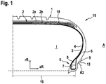
- the Fig. 1 shows a partial cross-section through a radial tire, which has a profiled tread 1, a belt 2 consisting of two layers 2a, 2b, which is covered by a bandage 18, a radial carcass 3, an airtight inner layer 4, side walls 6 and bead areas 5 with bead cores 7 and 8 core profiles.
- the pneumatic vehicle tire 10 is suitable for mounting on a rim 11 with a curved rim flange area 12 with a rim flange radius R1 of at least 9.5 mm, see for example Fig. 3 .
- a bead lip 9 running around the circumference of the tire side wall is arranged axially on the outside A of the tire 10 on at least one tire side wall 6.
- the bead lip 9 has a bead lip surface 13 axially on the outside A , which is wholly or partially intended to rest on the curved rim flange area 12.
- the bead lip surface 13 is concave when viewed in the tire cross section and has a radius of curvature R2 of R2 ⁇ 9.5 mm.
- It can be, for example, a radial tire for a van or a passenger car.
- FIG. 2 an enlargement of a partial cross-section of an exemplary embodiment of a pneumatic vehicle tire 10 according to the invention is shown at least in the area of the bead lip 9. For the sake of clarity, only the contour of the tire is shown. It can be the one in the Figure 1 act illustrated pneumatic vehicle tires 10. A contour of a rim 11 with a curved rim flange area 12 with a rim flange radius R1 of at least 9.5 mm is also shown. The two cross-sections are shown superimposed, the pneumatic vehicle tire 10 being shown in the unmounted state.
- the bead lip surface 13 has an arc of a circle 14 with a radius R2 of R2 ⁇ 9.5 mm.
- the radius R2 can meet a ratio R2 / 9.5 mm from 0.57 to 0.82, preferably from 0.65 to 0.73.
- the radius R2 can also be 6.0 mm to 8.0 mm, preferably approximately 7.0 mm.
- the circular arc 14 has an opening angle 15 of 40 ° to 55 °, preferably 43 ° to 50 °.
- the bead lip 9 begins at a radial height 16 of 13 mm to 15 mm and has a height extension 17 of 13.6 mm to 18.0 mm, preferably 13.6 mm to 15.6 mm.
- the height 16 is measured relative to the cross-sectional height of the nominal rim diameter at which the nominal rim width 19 is measured. With a rim diameter of less than or equal to 16 inches, a radial height 16 of 13.2 mm is preferred. For a rim diameter greater than 16 inches, a radial height 16 of 14 mm is preferred.
- the superimposition of the cross-sections of rim 11 and tire 10 in the unmounted state have an overlap 20 in the area of an axially outer bead lip edge 21 with an extension 22 perpendicular to the rim flange surface of 0.2 mm to 0.7 mm, preferably of approximately 0.3 mm , on.
- the superimposition of the cross-sections of rim 11 and tire 10 have, in the unmounted state, an overlap 20 in the area of an axially outer bead lip edge 21 with an axial extension 23 of 0.3 mm to 0.7 mm, preferably of approximately 0.5 mm .
- the concavely curved bead lip surface 13 extends, viewed in the tire cross section, axially outward to an edge 21 delimiting the bead lip 9.
- the bead lip 9 extends radially outward from the edge 21 to the sidewall 6 of the tire 10 and is flush with it, wherein the edge 21 is arranged axially within the maximum axial width of the side wall 6.
- the bead lip 9, viewed in the tire cross section, extends radially outward from the edge 21 axially within a conical envelope surface 24, which rests tangentially on the bead lip 9 in the area of the edge 21 and the side wall 6.
- the bead lip 9, viewed in the tire cross section, is preferably arranged axially outside the edge 21 from the edge 21 and is designed with a concave curvature 25.
- the rim is a rim 11 with a J-profile, preferably an aluminum rim with a J-profile, according to E.T.R.T.O. or according to TRA.
- the radius of curvature R1 is at least 9.5 mm.
- the Fig. 3 shows a vehicle wheel according to the invention comprising a rim 11 and a tire 10, the tire 10 being mounted on the rim 11. It can be rims and tires from the Figure 2 act. It can be the tire from the Figure 1 act.
- the pneumatic vehicle tire 10 is mounted on the rim 11 with a curved rim flange area 12 with a rim flange radius R1 of at least 9.5 mm.
- a bead lip 9 running around the circumference of the tire side wall is arranged at least on one tire side wall 6.
- the bead lip 9 has a bead lip surface 13 axially on the outside A , which rests wholly or partially on the curved rim flange area 12 of the rim 11.
- the bead lip surface 13 is concave when viewed in the tire cross-section and has a curvature in its cross-section in the unmounted state with a radius of curvature R2 of R2 ⁇ 9.5 mm, whereby in the assembled state shown there is a press fit between the bead lip 9 and the curved rim flange area 12.
Abstract
Fahrzeugluftreifen (10) geeignet zur Montage auf eine Felge (11) mit einem gekrümmten Felgenhornbereich (12) mit einem Felgenhornradius R1 von mindestens 9,5 mm. Die Erfindung betrifft weiter ein Fahrzeugrad aufweisend eine entsprechende Felge sowie einen auf der Felge montierten erfindungsgemäßen Reifen. Aufgabe der vorliegenden Erfindung ist es, eine verbesserte Haltbarkeit des Felgenhorns bezüglich Abriebs zu ermöglichen. Dies wird dadurch erreicht, dass axial außen (A) zumindest auf einer Reifenseitenwand (6) eine über den Umfang der Reifenseitenwand umlaufende Wulstlippe (9) angeordnet ist, dass die Wulstlippe (9) axial außen ( A ) eine Wulstlippenoberfläche (13) aufweist, die ganz oder teilweise zur Auflage auf den gekrümmten Felgenhornbereich (12) bestimmte ist, dass die Wulstlippenoberfläche (13) im Reifenquerschnitt betrachtet konkav gekrümmt ist und dabei einen Krümmungsradius R2 von R2 < 9,5 mm aufweist.Pneumatic vehicle tire (10) suitable for mounting on a rim (11) with a curved rim flange area (12) with a rim flange radius R1 of at least 9.5 mm. The invention further relates to a vehicle wheel having a corresponding rim and a tire according to the invention mounted on the rim. The object of the present invention is to enable an improved durability of the rim flange with regard to abrasion. This is achieved in that a bead lip (9) running around the circumference of the tire side wall is arranged axially on the outside (A) at least on one tire side wall (6), that the bead lip (9) has a bead lip surface (13) axially on the outside (A), which is intended wholly or partially to rest on the curved rim flange area (12) that the bead lip surface (13) is concave when viewed in the tire cross section and has a radius of curvature R2 of R2 <9.5 mm.
Description
Die Erfindung betrifft einen Fahrzeugluftreifen mit einem Laufstreifen, zwei Seitenwänden und zwei Wulstbereichen, wobei der Fahrzeugluftreifen geeignet ist zur Montage auf eine Felge mit einem gekrümmten Felgenhornbereich mit einem Felgenhornradius R1 von mindestens 9,5 mm.
Weiter betrifft die Erfindung ein Fahrzeugrad mit einem Fahrzeugluftreifen mit einem Laufstreifen, zwei Seitenwänden und zwei Wulstbereichen, wobei der Fahrzeugluftreifen auf einer Felge mit einem gekrümmten Felgenhornbereich mit einem Felgenhornradius R1 von mindestens 9,5 mm montiert ist.The invention relates to a pneumatic vehicle tire with a tread, two side walls and two bead areas, the pneumatic vehicle tire being suitable for mounting on a rim with a curved rim flange area with a rim flange radius R1 of at least 9.5 mm.
The invention also relates to a vehicle wheel with a pneumatic vehicle tire with a tread, two side walls and two bead areas, the pneumatic vehicle tire being mounted on a rim with a curved rim flange area with a rim flange radius R1 of at least 9.5 mm.
In Märkten mit feuchten Klimabedingungen und Sand (z.B. als Winterstreugut) auf der Fahrbahn kann es zu Abrieberscheinungen des Felgenhorns insbesondere von Aluminiumfelgen kommen. Die Ursache dafür ist, dass beim Einrollen des Reifens in seine Aufstandsfläche Relativbewegungen zwischen dem mit dem Felgenhorn in Berührung kommenden Wulststreifen des Reifens und dem Felgenhorn stattfinden. Wenn zuvor Sand zwischen den Wulststreifen und das Felgenhorn gelangt ist, können nachteilige Abrieberscheinungen auftreten.In markets with humid climatic conditions and sand (e.g. as winter grit) on the road, the rim flange, in particular aluminum rims, may wear. The reason for this is that when the tire rolls into its contact area, relative movements take place between the tire bead strip that comes into contact with the rim flange and the rim flange. If sand has previously got between the bead strips and the rim flange, disadvantageous abrasion phenomena can occur.
Bekannt sind Reifen aufweisend eine Felgenschutzrippe zum Schutz der Felge vor Bordsteinberührung. Diese steht am montierten Reifen üblicherweise axial über das Felgenhorn hinaus und ist radial beabstandet zum Felgenhorn angeordnet.Tires are known that have a rim protection rib to protect the rim from contact with the curb. This usually projects axially beyond the rim flange on the mounted tire and is arranged at a radial distance from the rim flange.
Aufgabe der vorliegenden Erfindung ist es, eine verbesserte Haltbarkeit des Felgenhorns bezüglich Abriebs zu ermöglichen.The object of the present invention is to enable an improved durability of the rim flange with regard to abrasion.
Die Aufgabe wird dadurch gelöst, dass axial außen zumindest auf einer Reifenseitenwand eine über den Umfang der Reifenseitenwand umlaufende Wulstlippe angeordnet ist, dass die Wulstlippe axial außen eine Wulstlippenoberfläche aufweist, die ganz oder teilweise zur Auflage auf den gekrümmten Felgenhornbereich bestimmte ist, dass die Wulstlippenoberfläche im Reifenquerschnitt betrachtet konkav gekrümmt ist und dabei einen Krümmungsradius R2 von R2 < 9,5 mm aufweist.The object is achieved in that a bead lip running around the circumference of the tire side wall is arranged axially on the outside at least on one tire side wall, that the bead lip has a bead lip surface axially on the outside, which is intended wholly or partially to rest on the curved rim flange area, that the bead lip surface in Tire cross-section is concavely curved and has a radius of curvature R2 of R2 <9.5 mm.
Erfindungswesentlich ist, dass die ganz oder teilweise zur Auflage auf einen gekrümmten Felgenhornbereich bestimmte Wulstlippenoberfläche konkav gekrümmt ist und dabei einen Krümmungsradius Radius R2 von R2 < 9,5 mm aufweist. Somit weist die Wulstlippenoberfläche einen geringeren Krümmungsradius R2 auf als der Felgenhornradius R1.It is essential to the invention that the bead lip surface, which is wholly or partially intended to rest on a curved rim flange area, is concavely curved and has a radius of curvature R2 of R2 <9.5 mm. The bead lip surface thus has a smaller radius of curvature R2 than the rim flange radius R1.
Durch das Verhältnis von R2/R1 < 1 ist bei einer Überlagerung der Konturen von Felge und Reifen im unmontierten Zustand eine Überschneidung der Wulstlippe im Bereich der Wulstlippenoberfläche und des Felgenhorns ermöglicht. Beim auf der Felge montierten Reifen ist somit, insbesondere beim Einrollen des Reifens in seine Aufstandsfläche, eine Presspassung ermöglicht. Die Wulstlippe erfüllt dann eine Abdichtfunktion zum Felgenhorn, wodurch der Felgenhornabrieb durch Partikel, die im Betrieb des Reifens zwischen Wulstbereich und Felgenhorn gelangen, verringert ist.The ratio of R2 / R1 <1 enables the bead lip to overlap in the area of the bead lip surface and the rim flange when the contours of the rim and tire are superimposed in the unmounted state. When the tire is mounted on the rim, a press fit is thus made possible, in particular when the tire rolls into its contact area. The bead lip then fulfills a sealing function with respect to the rim flange, as a result of which the rim flange abrasion due to particles that get between the bead area and the rim flange during operation of the tire is reduced.
Somit ist ein Reifen zur Verfügung gestellt, der im Betrieb eine verbesserte Haltbarkeit des Felgenhorns bezüglich Abriebs ermöglicht.Thus, a tire is made available which enables an improved durability of the rim flange with regard to abrasion during operation.
Der Beschreibung des erfindungsgemäßen Reifens wird der nicht auf die Felge aufgezogene vulkanisierte Reifen zugrunde gelegt. Die Bezeichnung der Krümmung als konkav oder konvex bezieht sich auf eine Blickrichtung von axial außen auf die Reifenoberfläche.The description of the tire according to the invention is based on the vulcanized tire not mounted on the rim. The designation of the curvature as concave or convex refers to a direction of view from the axially outside onto the tire surface.
Bei der Felge kann es sich um eine Felge mit J-Profil gemäß E.T.R.T.O. (European Tire and Rim Technical Organization) oder gemäß TRA (The Tire and Rim Association) handeln. Diese weisen einen als "R1" bezeichneten Felgenhornradius von mindestens 9,5 mm auf.The rim can be a J-profile rim according to E.T.R.T.O. (European Tire and Rim Technical Organization) or in accordance with TRA (The Tire and Rim Association). These have a rim flange radius, referred to as "R1", of at least 9.5 mm.
Eine vorteilhafte Ausführungsform ist dadurch gegeben, dass die Wulstlippenoberfläche einen Kreisbogen mit Radius R2 von R2 < 9,5 mm aufweist.An advantageous embodiment is given by the fact that the bead lip surface has an arc of a circle with a radius R2 of R2 <9.5 mm.
Hierdurch ist eine besonders geeignete Form der Wulstlippenoberfläche geschaffen.This creates a particularly suitable shape of the bead lip surface.
Eine weitere vorteilhafte Ausführungsform ist dadurch gegeben, dass der Radius R2 ein Verhältnis R2/9,5 mm von 0,57 bis 0,82, bevorzugt von 0,65 bis 0,73, erfüllt.A further advantageous embodiment is given by the fact that the radius R2 fulfills a ratio R2 / 9.5 mm of 0.57 to 0.82, preferably of 0.65 to 0.73.
Hierdurch kann über den gesamten Abrollzyklus eine Presspassung und damit eine Abdichtung zwischen Wulstlippe und Felgenhorn noch besser sichergestellt werden.As a result, a press fit and thus a seal between the bead lip and the rim flange can be ensured even better over the entire rolling cycle.
Eine vorteilhafte Ausführungsform ist auch dadurch gegeben, dass der Radius R2 6,0 mm bis 8,0 mm, bevorzugt in etwa 7,0 mm, beträgt.An advantageous embodiment is also given by the fact that the radius R2 is 6.0 mm to 8.0 mm, preferably approximately 7.0 mm.
Entsprechende Vorteile ergeben sich, wenn der Radius R2 6,0 mm bis 8,0 mm, bevorzugt in etwa 7,0 mm, aufweist.Corresponding advantages result if the radius R2 has 6.0 mm to 8.0 mm, preferably approximately 7.0 mm.
Als vorteilhaft hat es sich herausgestellt, wenn der Kreisbogen einen Öffnungswinkel von 40° bis 55°, bevorzugt von 43° bis 50°, aufweist.It has been found to be advantageous if the circular arc has an opening angle of 40 ° to 55 °, preferably 43 ° to 50 °.
Hierdurch steht ein für eine vorteilhafte Presspassung und damit eine Abdichtung ausreichender Bereich der Wulstlippenoberfläche zur Verfügung.This provides a sufficient area of the bead lip surface for an advantageous press fit and thus a seal.
Eine vorteilhafte Ausführungsform ist dadurch gegeben, dass die Wulstlippe auf einer radialen Höhe von 13,6 mm bis 18,0 mm, bevorzugt 13,6 mm bis 15,6 mm, aufweist.An advantageous embodiment is given by the fact that the bead lip has a radial height of 13.6 mm to 18.0 mm, preferably 13.6 mm to 15.6 mm.
Eine derartige radiale Erstreckung der Wulstlippe hat sich als besonders vorteilhaft herausgestellt.
Die Höhe bemisst sich relativ zur Querschnittshöhe des nominalen Felgendurchmessers, bei welchem die nominative Felgenbreite bemessen ist.Such a radial extension of the bead lip has proven to be particularly advantageous.
The height is measured relative to the cross-sectional height of the nominal rim diameter at which the nominal rim width is measured.
Bei einem Felgendurchmesser von kleiner gleich 16 Inch ist eine radiale Höhe von 13,2 mm bevorzugt. Für einen Felgendurchmesser von größer als 16 Inch ist eine radiale Höhe von 14 mm bevorzugt.With a rim diameter of less than or equal to 16 inches, a radial height of 13.2 mm is preferred. For a rim diameter greater than 16 inches, a radial height of 14 mm is preferred.
Eine weitere vorteilhafte Ausführungsform ist dadurch gegeben, dass eine Überlagerung der Querschnitte von Felge und Reifen in unmontiertem Zustand eine Überschneidung im Bereich einer axial äußeren Wulstlippenkante mit einer Erstreckung senkrecht zur Felgenhornoberfläche von 0,2 mm bis 0,7 mm, bevorzugt von in etwa 0,3 mm, aufweist.A further advantageous embodiment is given that an overlay of the cross sections of the rim and tire in the unmounted state an overlap in the area of an axially outer bead lip edge with an extension perpendicular to the rim flange surface of 0.2 mm to 0.7 mm, preferably of approximately 0 , 3 mm.
Hierdurch ist eine besonders vorteilhafte Presspassung ermöglicht.
Die Kante kann einen Winkel von maximal 90° aufweisen. Die Kante kann auch abgerundet, insbesondere konvex abgerundet, oder abgeschrägt sein. Die Kante kann auch eine Fase aufweisen.This enables a particularly advantageous press fit.
The edge can have an angle of a maximum of 90 °. The edge can also be rounded, in particular convexly rounded, or beveled. The edge can also have a bevel.
Entsprechende Vorteile ergeben sich, wenn eine Überlagerung der Querschnitte von Felge und Reifen in unmontiertem Zustand eine Überschneidung im Bereich einer axial äußeren Wulstlippenkante mit einer axialen Erstreckung von 0,3 mm bis 0,7 mm, bevorzugt in etwa 0,5 mm, aufweist.Corresponding advantages result when an overlay of the cross-sections of rim and tire in the unmounted state has an overlap in the area of an axially outer bead lip edge with an axial extension of 0.3 mm to 0.7 mm, preferably approximately 0.5 mm.
Eine vorteilhafte Ausführungsform ist auch dadurch gegeben, dass sich die konkav gekrümmte Wulstlippenoberfläche, im Reifenquerschnitt betrachtet, nach axial außen bis zu einer die Wulstlippe begrenzenden Kante erstreckt und dass sich die Wulstlippe von der Kante nach radial außen bis zur Seitenwand des Reifens erstreckt und mit dieser fluchtet, wobei die Kante axial innerhalb der maximalen axialen Breite der Seitenwand angeordnet ist.An advantageous embodiment is also given that the concavely curved bead lip surface, viewed in the tire cross-section, extends axially outward to an edge delimiting the bead lip and that the bead lip extends radially outward from the edge to the side wall of the tire and with it in alignment with the edge axially within the maximum axial width of the side wall.
Hierdurch ist eine Kontur ermöglicht, die bei einer Montage des Reifens auf einer Felge der die gesamte mit dem Felgenhorn in Berührung kommende Oberfläche der Wulstlippe durch die Wulstlippenoberfläche gebildet ist. Hierdurch ist eine besonders vorteilhafte Abdichtung zwischen Wulstlippe und Felgenhorn ermöglicht.This enables a contour which, when the tire is mounted on a rim, of the entire surface of the bead lip that comes into contact with the rim flange is formed by the bead lip surface. This enables a particularly advantageous seal between the bead lip and the rim flange.
Die Kante kann einen Winkel von maximal 90° aufweisen. Die Kante kann auch abgerundet, insbesondere konvex abgerundet, oder abgeschrägt sein. Die Kante kann auch eine Fase aufweisen.The edge can have an angle of a maximum of 90 °. The edge can also be rounded, in particular convexly rounded, or beveled. The edge can also have a bevel.
Eine weitere vorteilhafte Ausführungsform ist dadurch gegeben, dass sich die Wulstlippe, im Reifenquerschnitt betrachtet, von der Kante aus nach radial außen axial innerhalb einer kegelförmigen Hüllfläche erstreckt, welche tangential an der Wulstlippe im Bereich der Kante sowie der Seitenwand anliegt, bevorzugt dass sich die Wulstlippe, im Reifenquerschnitt betrachtet, von der Kante aus axial außerhalb der Kante angeordnet und mit einer konkaven Krümmung ausgebildet ist.A further advantageous embodiment is given by the fact that the bead lip, viewed in the tire cross-section, extends from the edge radially outward axially within a conical envelope surface, which rests tangentially on the bead lip in the area of the edge and the side wall, preferably that the bead lip , viewed in the tire cross-section, is arranged axially outside the edge from the edge and is designed with a concave curvature.
Hierdurch sind die Vorteile in der Haltbarkeit bei gleichzeitig geringem Materialeinsatz ermöglicht. Ein geringer Materialeinsatz wirkt sich vorteilhaft auf die Materialkosten, das Gewicht sowie den Rollwiderstand des Reifens aus.This enables the advantages in terms of durability while at the same time using little material. A low use of material has a beneficial effect on the material costs, the weight and the rolling resistance of the tire.
Eine konkave Krümmung des Wulstlippenquerschnitts ermöglicht bei vorteilhaftem Geräuschverhalten einen besonders geringen Materialeinsatz.A concave curvature of the bead lip cross-section enables a particularly low use of material with an advantageous noise behavior.
Vorteilhaft ist es, wenn sich der Fahrzeugluftreifen zur Montage auf einer Felge mit J-Profil, bevorzugt auf einer Aluminiumfelge mit J-Profil, eignet.It is advantageous if the pneumatic vehicle tire is suitable for mounting on a rim with a J-profile, preferably on an aluminum rim with a J-profile.
Derartige Felgen weisen gemäß E.T.R.T.O. oder gemäß TRA einen minimalen Felgenhornradius R1 von 9,5 mm auf. Die spezielle Form der Wulstlippe ist besonders zum Schutz von Felgen mit J-Profil, bevorzugt von Aluminiumfelgen mit J Profil, geeignet.Such rims have a minimum rim flange radius R1 of 9.5 mm according to ETRTO or according to TRA. The special shape of the bead lip is particularly suitable for protecting rims with a J profile, preferably aluminum rims with a J profile.
Eine vorteilhafte Ausführungsform ist dadurch gegeben, dass der Reifen für einen Van oder für einen Personenkraftwagen, bevorzugt für einen Van, geeignet ist.An advantageous embodiment is given by the fact that the tire is suitable for a van or for a passenger car, preferably for a van.
Van Reifen weisen im Vergleich zu Reifen für Personenkraftwagen höhere Wulstbelastungen auf. Hierdurch kann ein höherer Abrieb des Felgenhorns entstehen, sodass sich besonders hier der positive Effekt der speziellen Kontur der Wulstlippe bemerkbar macht. Ein vorteilhafter Felgenschutz gegenüber Abrieb ist aber auch für Reifen für Personenkraftwagen gegeben. Bevorzugt ist der Reifen dabei für eine Felge mit J-Profil geeignet.Van tires have higher bead loads compared to tires for passenger cars. This can result in higher abrasion of the rim flange, so that the positive effect of the special contour of the bead lip is particularly noticeable here. An advantageous rim protection against abrasion is also given for tires for passenger cars. The tire is preferably suitable for a rim with a J-profile.
Der erfindungsgemäße Reifen kann sich aber auch für andere Einsatzgebiete eignen.The tire according to the invention can, however, also be suitable for other areas of use.
Die Aufgabe wird bezüglich des Fahrzeugrades dadurch gelöst, dass axial außen zumindest auf einer Reifenseitenwand eine über den Umfang der Reifenseitenwand umlaufende Wulstlippe angeordnet ist, dass die Wulstlippe axial außen eine Wulstlippenoberfläche aufweist, die ganz oder teilweise auf dem gekrümmten Felgenhornbereich der Felge aufliegt, dass die Wulstlippenoberfläche im Reifenquerschnitt betrachtet konkav gekrümmt ist und dabei im unmontierten Zustand in ihrem Querschnitt eine Krümmung aufweisend einen Krümmungsradius R2 von R2 < 9,5 mm umfasst, wodurch im montierten Zustand eine Presspassung zwischen Wulstlippe und dem gekrümmten Felgenhornbereich erfolgt.The object is achieved with regard to the vehicle wheel in that a bead lip running around the circumference of the tire side wall is arranged axially on the outside at least on one tire side wall, that the bead lip has a bead lip surface axially on the outside that rests wholly or partially on the curved rim flange area of the rim, that the The bead lip surface is concavely curved when viewed in the tire cross-section and, in the unmounted state, has a curvature in its cross-section with a radius of curvature R2 of R2 <9.5 mm, whereby in the assembled state there is a press fit between the bead lip and the curved rim flange area.
Beim auf der Felge montierten Reifen ist somit, insbesondere beim Einrollen des Reifens in seine Aufstandsfläche, eine Presspassung ermöglicht. Die Wulstlippe erfüllt dann eine Abdichtfunktion zum Felgenhorn, wodurch der Felgenhornabrieb durch Partikel, die im Betrieb des Reifens zwischen Wulstbereich und Felgenhorn gelangen, verringert ist.When the tire is mounted on the rim, a press fit is thus made possible, in particular when the tire rolls into its contact area. The bead lip then fulfills a sealing function with respect to the rim flange, as a result of which the rim flange abrasion due to particles that get between the bead area and the rim flange during operation of the tire is reduced.
Somit ist ein Fahrzeugrad zur Verfügung gestellt, welches im Betrieb eine verbesserte Haltbarkeit des Felgenhorns bezüglich Abriebs aufweist.A vehicle wheel is thus made available which, during operation, has an improved durability of the rim flange with regard to abrasion.
Es kann sich bei dem Reifen um einen erfindungsgemäßen Reifen gemäß den vorangegangenen Ausführungen handeln. Die Felge ist bevorzugt eine Felge mit J-Profil gemäß E.T.R.T.O. oder TRA.The tire can be a tire according to the invention in accordance with the preceding statements. The rim is preferably a rim with a J-profile according to E.T.R.T.O. or TRA.
Weitere Merkmale, Vorteile und Einzelheiten der Erfindung werden anhand der Zeichnungen, die schematische Ausführungsbeispiele darstellen, näher erläutert. Es zeigen die
-
Fig. 1 einen Teilquerschnitt durch einen erfindungsgemäßen Reifen; -
Fig. 2 einen Teilquerschnitt durch einen erfindungsgemäßen Reifen und eine Felge; -
Fig. 3 einen Teilquerschnitt durch einen auf einer Felge montierten erfindungsgemäßen Reifen.
-
Fig. 1 a partial cross section through a tire according to the invention; -
Fig. 2 a partial cross section through a tire according to the invention and a rim; -
Fig. 3 a partial cross-section through a tire according to the invention mounted on a rim.
Die
Am Reifen 10 ist axial außen A zumindest auf einer Reifenseitenwand 6 eine über den Umfang der Reifenseitenwand umlaufende Wulstlippe 9 angeordnet. Die Wulstlippe 9 weist axial außen A eine Wulstlippenoberfläche 13 auf, die ganz oder teilweise zur Auflage auf den gekrümmten Felgenhornbereich 12 bestimmte ist. Die Wulstlippenoberfläche 13 ist im Reifenquerschnitt betrachtet konkav gekrümmt und weist dabei einen Krümmungsradius R2 von R2 < 9,5 mm auf.A
Es kann sich z.B. um einen Radialreifen für einen Van oder einen Personenkraftwagen handeln.It can be, for example, a radial tire for a van or a passenger car.
In der
Die Wulstlippenoberfläche 13 weist einen Kreisbogen 14 mit Radius R2 von R2 < 9,5 mm aufweist. Der Radius R2 kann ein Verhältnis R2/9,5 mm von 0,57 bis 0,82, bevorzugt von 0,65 bis 0,73, erfüllen. Der Radius R2 kann auch 6,0 mm bis 8,0 mm, bevorzugt in etwa 7,0 mm, betragen. Der Kreisbogen 14 weist einen Öffnungswinkel 15 von 40° bis 55°, bevorzugt von 43° bis 50°, auf.The
Die Wulstlippe 9 beginnt auf einer radialen Höhe 16 von 13 mm bis 15 mm und weist eine Höhenerstreckung 17 von 13,6 mm bis 18,0 mm, bevorzugt 13,6 mm bis 15,6 mm, auf. Die Höhe 16 bemisst sich relativ zur Querschnittshöhe des nominalen Felgendurchmessers, bei welchem die nominative Felgenbreite 19 bemessen ist. Bei einem Felgendurchmesser von kleiner gleich 16 Inch ist eine radiale Höhe 16 von 13,2 mm bevorzugt. Für einen Felgendurchmesser von größer als 16 Inch ist eine radiale Höhe 16 von 14 mm bevorzugt.The
Die Überlagerung der Querschnitte von Felge 11 und Reifen 10 weisen in unmontiertem Zustand eine Überschneidung 20 im Bereich einer axial äußeren Wulstlippenkante 21 mit einer Erstreckung 22 senkrecht zur Felgenhornoberfläche von 0,2 mm bis 0,7 mm, bevorzugt von in etwa 0,3 mm, auf.
Die Überlagerung der Querschnitte von Felge 11 und Reifen 10 weisen in unmontiertem Zustand eine Überschneidung 20 im Bereich einer axial äußeren Wulstlippenkante 21 mit einer axialen Erstreckung 23 von 0,3 mm bis 0,7 mm, bevorzugt von in etwa 0,5 mm, auf.The superimposition of the cross-sections of
The superimposition of the cross-sections of
Die konkav gekrümmte Wulstlippenoberfläche 13 erstreckt sich, im Reifenquerschnitt betrachtet, nach axial außen bis zu einer die Wulstlippe 9 begrenzenden Kante 21. Die Wulstlippe 9 erstreckt sich dabei von der Kante 21 nach radial außen bis zur Seitenwand 6 des Reifens 10 und fluchtet mit dieser, wobei die Kante 21 axial innerhalb der maximalen axialen Breite der Seitenwand 6 angeordnet ist.The concavely curved
Die Wulstlippe 9 erstreckt sich dabei, im Reifenquerschnitt betrachtet, von der Kante 21 aus nach radial außen axial innerhalb einer kegelförmigen Hüllfläche 24, welche tangential an der Wulstlippe 9 im Bereich der Kante 21 sowie der Seitenwand 6 anliegt. Bevorzugt ist die Wulstlippe 9, im Reifenquerschnitt betrachtet, von der Kante 21 aus axial außerhalb der Kante 21 angeordnet und mit einer konkaven Krümmung 25 ausgebildet.The
Die Felge ist eine Felge 11 mit J-Profil, bevorzugt eine Aluminiumfelge mit J-Profil, gemäß E.T.R.T.O. oder gemäß TRA. Der Krümmungsradius R1 beträgt minimal 9,5 mm.The rim is a
Die
Der Fahrzeugluftreifen 10 ist auf der Felge 11 mit einem gekrümmten Felgenhornbereich 12 mit einem Felgenhornradius R1 von mindestens 9,5 mm montiert. Axial außen A ist dabei zumindest auf einer Reifenseitenwand 6 eine über den Umfang der Reifenseitenwand umlaufende Wulstlippe 9 angeordnet. Die Wulstlippe 9 weist axial außen A eine Wulstlippenoberfläche 13 auf, die ganz oder teilweise auf dem gekrümmten Felgenhornbereich 12 der Felge 11 aufliegt. Die Wulstlippenoberfläche 13 ist im Reifenquerschnitt betrachtet konkav gekrümmt und weist dabei im unmontierten Zustand in ihrem Querschnitt eine Krümmung mit einem Krümmungsradius R2 von R2 < 9,5 mm auf, wodurch im montierten dargestellten Zustand eine Presspassung zwischen Wulstlippe 9 und dem gekrümmten Felgenhornbereich 12 erfolgt.The
- 11
- LaufstreifenTreads
- 22
- Gürtelbelt
- 33
- Karkassecarcass
- 44th
- InnenschichtInner layer
- 55
- WulstbereichBead area
- 66th
- SeitenwandSide wall
- 77th
- WulstkernBead core
- 88th
- KernreiterApex
- 99
- WulstlippeBulbous lip
- 1010
- FahrzeugluftreifenaPneumatic vehicle tires
- 1111
- Felgerim
- 1212th
- gekrümmter Felgenhornbereichcurved rim flange area
- 1313th
- WulstlippenoberflächeBulbous lip surface
- 1414th
- KreisbogenCircular arc
- 1515th
- ÖffnungswinkelOpening angle
- 1616
- Höheheight
- 1717th
- HöhenerstreckungHeight extension
- 1818th
- BandagenlageBandage layer
- 1919th
- nominative Felgenbreitenominative rim width
- 2020th
- Überschneidungoverlap
- 2121
- WulstlippenkanteBead lip edge
- 2222nd
- ErstreckungExtension
- 2323
- axiale Erstreckungaxial extension
- 2424
- HüllflächeEnvelope surface
- 2525th
- Krümmungcurvature
- R1R1
- FelgenhornradiusRim flange radius
- R2R2
- KrümmungsradiusRadius of curvature
- AA.
- axial außenaxially outside
- II.
- axial innenaxially inside
- rRrR
- radiale Richtungradial direction
- aRaR
- axiale Richtungaxial direction
Claims (13)
dadurch gekennzeichnet, dass
characterized in that
dadurch gekennzeichnet, dass der Radius R2 ein Verhältnis R2/9,5 mm von 0,57 bis 0,82, bevorzugt von 0,65 bis 0,73, erfüllt.Pneumatic vehicle tire (10) according to at least one of the preceding claims,
characterized in that the radius R2 fulfills a ratio R2 / 9.5 mm from 0.57 to 0.82, preferably from 0.65 to 0.73.
dadurch gekennzeichnet, dass der Radius R2 6,0 mm bis 8,0 mm, bevorzugt in etwa 7,0 mm, beträgt.Pneumatic vehicle tire (10) according to at least one of the preceding claims,
characterized in that the radius R2 is 6.0 mm to 8.0 mm, preferably approximately 7.0 mm.
dadurch gekennzeichnet, dass die Wulstlippe (9) auf einer radialen Höhe (16) von 13,6 mm bis 18,0 mm, bevorzugt 13,6 mm bis 15,6 mm, aufweist.Pneumatic vehicle tire (10) according to at least one of the preceding claims,
characterized in that the bead lip (9) has a radial height (16) of 13.6 mm to 18.0 mm, preferably 13.6 mm to 15.6 mm.
dadurch gekennzeichnet, dass eine Überlagerung der Querschnitte von Felge (11) und Reifen (12) in unmontiertem Zustand eine Überschneidung (20) im Bereich einer axial äußeren Wulstlippenkante (21) mit einer Erstreckung (22) senkrecht zur Felgenhornoberfläche von 0,2 mm bis 0,7 mm, bevorzugt von in etwa 0,3 mm, aufweist.Pneumatic vehicle tire (10) according to at least one of the preceding claims,
characterized in that an overlay of the cross sections of rim (11) and tire (12) in the unmounted state an overlap (20) in the area of an axially outer bead lip edge (21) with an extension (22) perpendicular to the rim flange surface of 0.2 mm to 0.7 mm, preferably of about 0.3 mm.
dadurch gekennzeichnet, dass eine Überlagerung der Querschnitte von Felge (11) und Reifen (12) in unmontiertem Zustand eine Überschneidung (20) im Bereich einer axial äußeren Wulstlippenkante (21) mit einer axialen Erstreckung (23) von 0,3 mm bis 0,7 mm, bevorzugt in etwa 0,5 mm, aufweist.Pneumatic vehicle tire (10) according to at least one of the preceding claims,
characterized in that an overlay of the cross sections of rim (11) and tire (12) in the unmounted state an overlap (20) in the area of an axially outer bead lip edge (21) with an axial extension (23) of 0.3 mm to 0, 7 mm, preferably about 0.5 mm.
dadurch gekennzeichnet, dass sich die konkav gekrümmte Wulstlippenoberfläche (13), im Reifenquerschnitt betrachtet, nach axial außen bis zu einer die Wulstlippe (9) begrenzenden Kante (21) erstreckt und dass sich die Wulstlippe (9) von der Kante (21) nach radial außen bis zur Seitenwand (6) des Reifens (10) erstreckt und mit dieser fluchtet, wobei die Kante (21) axial innerhalb der maximalen axialen Breite der Seitenwand angeordnet ist.Pneumatic vehicle tire (10) according to at least one of the preceding claims,
characterized in that the concavely curved bead lip surface (13), viewed in the tire cross section, extends axially outward to an edge (21) delimiting the bead lip (9) and that the bead lip (9) extends radially from the edge (21) extends outwardly to the sidewall (6) of the tire (10) and is in alignment therewith, the edge (21) being arranged axially within the maximum axial width of the sidewall.
dadurch gekennzeichnet, dass sich der Fahrzeugluftreifen (10) zur Montage auf einer Felge (11) mit J-Profil, bevorzugt auf einer Aluminiumfelge mit J-Profil, eignet.Pneumatic vehicle tire (10) according to at least one of the preceding claims,
characterized in that the pneumatic vehicle tire (10) is suitable for mounting on a rim (11) with a J-profile, preferably on an aluminum rim with a J-profile.
dadurch gekennzeichnet, dass der Reifen für einen Van oder für einen Personenkraftwagen, bevorzugt für einen Van, geeignet ist.Pneumatic vehicle tire (10) according to at least one of the preceding claims,
characterized in that the tire is suitable for a van or for a passenger car, preferably for a van.
dadurch gekennzeichnet, dass
characterized in that
Applications Claiming Priority (1)
| Application Number | Priority Date | Filing Date | Title |
|---|---|---|---|
| DE102019218120.1A DE102019218120A1 (en) | 2019-11-25 | 2019-11-25 | Pneumatic vehicle tires having a bead lip |
Publications (2)
| Publication Number | Publication Date |
|---|---|
| EP3825154A1 true EP3825154A1 (en) | 2021-05-26 |
| EP3825154B1 EP3825154B1 (en) | 2023-12-06 |
Family
ID=72943921
Family Applications (1)
| Application Number | Title | Priority Date | Filing Date |
|---|---|---|---|
| EP20202478.2A Active EP3825154B1 (en) | 2019-11-25 | 2020-10-19 | Pneumatic vehicle tyre with a beaded lip |
Country Status (2)
| Country | Link |
|---|---|
| EP (1) | EP3825154B1 (en) |
| DE (1) | DE102019218120A1 (en) |
Cited By (1)
| Publication number | Priority date | Publication date | Assignee | Title |
|---|---|---|---|---|
| EP4272977A1 (en) * | 2022-05-06 | 2023-11-08 | Continental Reifen Deutschland GmbH | Pneumatic tyre for vehicles |
Citations (6)
| Publication number | Priority date | Publication date | Assignee | Title |
|---|---|---|---|---|
| DE3616199A1 (en) * | 1986-05-14 | 1987-11-19 | Continental Gummi Werke Ag | Vehicle wheel consisting of pneumatic tyre and of rim |
| EP1036675A2 (en) * | 1999-03-18 | 2000-09-20 | Sumitomo Rubber Industries Limited | Pneumatic tyre |
| JP2007160983A (en) * | 2005-12-09 | 2007-06-28 | Yokohama Rubber Co Ltd:The | Pneumatic tire |
| DE102007049943A1 (en) * | 2007-10-18 | 2009-04-23 | Sumitomo Rubber Industries Ltd., Kobe | Vehicle tires |
| EP2127913A1 (en) * | 2008-05-30 | 2009-12-02 | Michele Ventrella | Vehicle tyres with side support profile |
| EP2433818A1 (en) * | 2010-09-22 | 2012-03-28 | Jonny Janus | Vehicle tyre for a multi-track vehicle |
-
2019
- 2019-11-25 DE DE102019218120.1A patent/DE102019218120A1/en active Pending
-
2020
- 2020-10-19 EP EP20202478.2A patent/EP3825154B1/en active Active
Patent Citations (6)
| Publication number | Priority date | Publication date | Assignee | Title |
|---|---|---|---|---|
| DE3616199A1 (en) * | 1986-05-14 | 1987-11-19 | Continental Gummi Werke Ag | Vehicle wheel consisting of pneumatic tyre and of rim |
| EP1036675A2 (en) * | 1999-03-18 | 2000-09-20 | Sumitomo Rubber Industries Limited | Pneumatic tyre |
| JP2007160983A (en) * | 2005-12-09 | 2007-06-28 | Yokohama Rubber Co Ltd:The | Pneumatic tire |
| DE102007049943A1 (en) * | 2007-10-18 | 2009-04-23 | Sumitomo Rubber Industries Ltd., Kobe | Vehicle tires |
| EP2127913A1 (en) * | 2008-05-30 | 2009-12-02 | Michele Ventrella | Vehicle tyres with side support profile |
| EP2433818A1 (en) * | 2010-09-22 | 2012-03-28 | Jonny Janus | Vehicle tyre for a multi-track vehicle |
Cited By (1)
| Publication number | Priority date | Publication date | Assignee | Title |
|---|---|---|---|---|
| EP4272977A1 (en) * | 2022-05-06 | 2023-11-08 | Continental Reifen Deutschland GmbH | Pneumatic tyre for vehicles |
Also Published As
| Publication number | Publication date |
|---|---|
| EP3825154B1 (en) | 2023-12-06 |
| DE102019218120A1 (en) | 2021-05-27 |
Similar Documents
| Publication | Publication Date | Title |
|---|---|---|
| DE8035189U1 (en) | WHEEL RIM | |
| DE102006002455B4 (en) | tire | |
| EP3038843B1 (en) | Pneumatic vehicle tyre | |
| EP2135753A2 (en) | Vehicle pneumatic tire with a rim protector | |
| DE69819242T2 (en) | Truck tires | |
| DE102014207771A1 (en) | Pneumatic vehicle tire with squeegee position | |
| EP3825154B1 (en) | Pneumatic vehicle tyre with a beaded lip | |
| EP2119574B1 (en) | Bearing surface profile of a vehicle tyre | |
| DE19722521A1 (en) | Pneumatic vehicle tires | |
| EP0726173B1 (en) | Wear indicator on the sidewall of motor-vehicle tyres, particularly for lorries and buses | |
| WO2012159809A1 (en) | Vehicle pneumatic tyre | |
| EP3362300B1 (en) | Commercial vehicle tires | |
| WO2006128550A1 (en) | Tread profile with asymmetric circumferential grooves for a commercial vehicle tyre | |
| EP4054866B1 (en) | Pneumatic vehicle tyre having a rim protection rib | |
| EP0131117B1 (en) | Vehicle wheel | |
| EP1346852B1 (en) | Tyre | |
| WO2019115055A1 (en) | Pneumatic tire for a vehicle | |
| DE19715866A1 (en) | Run-flat wheel for cars and lorries | |
| DE102017211125A1 (en) | bicycle tires | |
| DE102012107606A1 (en) | Self-sealing pneumatic tire for vehicle, has inner layers, where central part of inner layers is radially and circumferentially provided above sealing layer around circumference of tire, and part comprising reprocessed rubber mixture | |
| DE2414885A1 (en) | Safety wheel rim for tubeless tyre - having hard rubber layer over rim and edges attached by vulcanisation | |
| EP3564046B1 (en) | Pneumatic tyre | |
| DE102019206591A1 (en) | Pneumatic vehicle tires | |
| WO2023078513A1 (en) | Dimensionally stable pneumatic vehicle tire | |
| DE102020215727A1 (en) | commercial vehicle tires |
Legal Events
| Date | Code | Title | Description |
|---|---|---|---|
| PUAI | Public reference made under article 153(3) epc to a published international application that has entered the european phase |
Free format text: ORIGINAL CODE: 0009012 |
|
| STAA | Information on the status of an ep patent application or granted ep patent |
Free format text: STATUS: THE APPLICATION HAS BEEN PUBLISHED |
|
| AK | Designated contracting states |
Kind code of ref document: A1 Designated state(s): AL AT BE BG CH CY CZ DE DK EE ES FI FR GB GR HR HU IE IS IT LI LT LU LV MC MK MT NL NO PL PT RO RS SE SI SK SM TR |
|
| STAA | Information on the status of an ep patent application or granted ep patent |
Free format text: STATUS: REQUEST FOR EXAMINATION WAS MADE |
|
| 17P | Request for examination filed |
Effective date: 20211126 |
|
| RBV | Designated contracting states (corrected) |
Designated state(s): AL AT BE BG CH CY CZ DE DK EE ES FI FR GB GR HR HU IE IS IT LI LT LU LV MC MK MT NL NO PL PT RO RS SE SI SK SM TR |
|
| STAA | Information on the status of an ep patent application or granted ep patent |
Free format text: STATUS: EXAMINATION IS IN PROGRESS |
|
| 17Q | First examination report despatched |
Effective date: 20220901 |
|
| GRAP | Despatch of communication of intention to grant a patent |
Free format text: ORIGINAL CODE: EPIDOSNIGR1 |
|
| STAA | Information on the status of an ep patent application or granted ep patent |
Free format text: STATUS: GRANT OF PATENT IS INTENDED |
|
| INTG | Intention to grant announced |
Effective date: 20230712 |
|
| GRAS | Grant fee paid |
Free format text: ORIGINAL CODE: EPIDOSNIGR3 |
|
| P01 | Opt-out of the competence of the unified patent court (upc) registered |
Effective date: 20230911 |
|
| GRAA | (expected) grant |
Free format text: ORIGINAL CODE: 0009210 |
|
| STAA | Information on the status of an ep patent application or granted ep patent |
Free format text: STATUS: THE PATENT HAS BEEN GRANTED |
|
| AK | Designated contracting states |
Kind code of ref document: B1 Designated state(s): AL AT BE BG CH CY CZ DE DK EE ES FI FR GB GR HR HU IE IS IT LI LT LU LV MC MK MT NL NO PL PT RO RS SE SI SK SM TR |
|
| REG | Reference to a national code |
Ref country code: GB Ref legal event code: FG4D Free format text: NOT ENGLISH |
|
| REG | Reference to a national code |
Ref country code: CH Ref legal event code: EP |
|
| REG | Reference to a national code |
Ref country code: DE Ref legal event code: R096 Ref document number: 502020006288 Country of ref document: DE |
|
| REG | Reference to a national code |
Ref country code: IE Ref legal event code: FG4D Free format text: LANGUAGE OF EP DOCUMENT: GERMAN |
|
| RAP4 | Party data changed (patent owner data changed or rights of a patent transferred) |
Owner name: CONTINENTAL REIFEN DEUTSCHLAND GMBH |
|
| REG | Reference to a national code |
Ref country code: DE Ref legal event code: R081 Ref document number: 502020006288 Country of ref document: DE Owner name: CONTINENTAL REIFEN DEUTSCHLAND GMBH, DE Free format text: FORMER OWNER: CONTINENTAL REIFEN DEUTSCHLAND GMBH, 30165 HANNOVER, DE |
|
| REG | Reference to a national code |
Ref country code: LT Ref legal event code: MG9D |
|
| PG25 | Lapsed in a contracting state [announced via postgrant information from national office to epo] |
Ref country code: GR Free format text: LAPSE BECAUSE OF FAILURE TO SUBMIT A TRANSLATION OF THE DESCRIPTION OR TO PAY THE FEE WITHIN THE PRESCRIBED TIME-LIMIT Effective date: 20240307 |
|
| REG | Reference to a national code |
Ref country code: NL Ref legal event code: MP Effective date: 20231206 |
|
| PG25 | Lapsed in a contracting state [announced via postgrant information from national office to epo] |
Ref country code: LT Free format text: LAPSE BECAUSE OF FAILURE TO SUBMIT A TRANSLATION OF THE DESCRIPTION OR TO PAY THE FEE WITHIN THE PRESCRIBED TIME-LIMIT Effective date: 20231206 |