EP3825133A2 - Printing device and information processing device - Google Patents
Printing device and information processing device Download PDFInfo
- Publication number
- EP3825133A2 EP3825133A2 EP20205920.0A EP20205920A EP3825133A2 EP 3825133 A2 EP3825133 A2 EP 3825133A2 EP 20205920 A EP20205920 A EP 20205920A EP 3825133 A2 EP3825133 A2 EP 3825133A2
- Authority
- EP
- European Patent Office
- Prior art keywords
- image
- frame member
- recording medium
- printing
- placing
- Prior art date
- Legal status (The legal status is an assumption and is not a legal conclusion. Google has not performed a legal analysis and makes no representation as to the accuracy of the status listed.)
- Granted
Links
Images







Classifications
-
- H—ELECTRICITY
- H04—ELECTRIC COMMUNICATION TECHNIQUE
- H04N—PICTORIAL COMMUNICATION, e.g. TELEVISION
- H04N1/00—Scanning, transmission or reproduction of documents or the like, e.g. facsimile transmission; Details thereof
- H04N1/00567—Handling of original or reproduction media, e.g. cutting, separating, stacking
- H04N1/00663—Indicating relating to handling of media
-
- B—PERFORMING OPERATIONS; TRANSPORTING
- B41—PRINTING; LINING MACHINES; TYPEWRITERS; STAMPS
- B41J—TYPEWRITERS; SELECTIVE PRINTING MECHANISMS, i.e. MECHANISMS PRINTING OTHERWISE THAN FROM A FORME; CORRECTION OF TYPOGRAPHICAL ERRORS
- B41J3/00—Typewriters or selective printing or marking mechanisms characterised by the purpose for which they are constructed
- B41J3/407—Typewriters or selective printing or marking mechanisms characterised by the purpose for which they are constructed for marking on special material
- B41J3/4073—Printing on three-dimensional objects not being in sheet or web form, e.g. spherical or cubic objects
- B41J3/40731—Holders for objects, e. g. holders specially adapted to the shape of the object to be printed or adapted to hold several objects
-
- B—PERFORMING OPERATIONS; TRANSPORTING
- B41—PRINTING; LINING MACHINES; TYPEWRITERS; STAMPS
- B41J—TYPEWRITERS; SELECTIVE PRINTING MECHANISMS, i.e. MECHANISMS PRINTING OTHERWISE THAN FROM A FORME; CORRECTION OF TYPOGRAPHICAL ERRORS
- B41J3/00—Typewriters or selective printing or marking mechanisms characterised by the purpose for which they are constructed
- B41J3/407—Typewriters or selective printing or marking mechanisms characterised by the purpose for which they are constructed for marking on special material
- B41J3/4073—Printing on three-dimensional objects not being in sheet or web form, e.g. spherical or cubic objects
-
- B—PERFORMING OPERATIONS; TRANSPORTING
- B41—PRINTING; LINING MACHINES; TYPEWRITERS; STAMPS
- B41J—TYPEWRITERS; SELECTIVE PRINTING MECHANISMS, i.e. MECHANISMS PRINTING OTHERWISE THAN FROM A FORME; CORRECTION OF TYPOGRAPHICAL ERRORS
- B41J11/00—Devices or arrangements of selective printing mechanisms, e.g. ink-jet printers or thermal printers, for supporting or handling copy material in sheet or web form
- B41J11/20—Platen adjustments for varying the strength of impression, for a varying number of papers, for wear or for alignment, or for print gap adjustment
-
- B—PERFORMING OPERATIONS; TRANSPORTING
- B41—PRINTING; LINING MACHINES; TYPEWRITERS; STAMPS
- B41J—TYPEWRITERS; SELECTIVE PRINTING MECHANISMS, i.e. MECHANISMS PRINTING OTHERWISE THAN FROM A FORME; CORRECTION OF TYPOGRAPHICAL ERRORS
- B41J3/00—Typewriters or selective printing or marking mechanisms characterised by the purpose for which they are constructed
- B41J3/44—Typewriters or selective printing mechanisms having dual functions or combined with, or coupled to, apparatus performing other functions
- B41J3/445—Printers integrated in other types of apparatus, e.g. printers integrated in cameras
-
- B—PERFORMING OPERATIONS; TRANSPORTING
- B41—PRINTING; LINING MACHINES; TYPEWRITERS; STAMPS
- B41J—TYPEWRITERS; SELECTIVE PRINTING MECHANISMS, i.e. MECHANISMS PRINTING OTHERWISE THAN FROM A FORME; CORRECTION OF TYPOGRAPHICAL ERRORS
- B41J3/00—Typewriters or selective printing or marking mechanisms characterised by the purpose for which they are constructed
- B41J3/44—Typewriters or selective printing mechanisms having dual functions or combined with, or coupled to, apparatus performing other functions
- B41J3/46—Printing mechanisms combined with apparatus providing a visual indication
-
- G—PHYSICS
- G06—COMPUTING OR CALCULATING; COUNTING
- G06F—ELECTRIC DIGITAL DATA PROCESSING
- G06F3/00—Input arrangements for transferring data to be processed into a form capable of being handled by the computer; Output arrangements for transferring data from processing unit to output unit, e.g. interface arrangements
- G06F3/12—Digital output to print unit, e.g. line printer, chain printer
- G06F3/1201—Dedicated interfaces to print systems
- G06F3/1202—Dedicated interfaces to print systems specifically adapted to achieve a particular effect
- G06F3/1203—Improving or facilitating administration, e.g. print management
- G06F3/1208—Improving or facilitating administration, e.g. print management resulting in improved quality of the output result, e.g. print layout, colours, workflows, print preview
-
- G—PHYSICS
- G06—COMPUTING OR CALCULATING; COUNTING
- G06F—ELECTRIC DIGITAL DATA PROCESSING
- G06F3/00—Input arrangements for transferring data to be processed into a form capable of being handled by the computer; Output arrangements for transferring data from processing unit to output unit, e.g. interface arrangements
- G06F3/12—Digital output to print unit, e.g. line printer, chain printer
- G06F3/1201—Dedicated interfaces to print systems
- G06F3/1223—Dedicated interfaces to print systems specifically adapted to use a particular technique
- G06F3/1237—Print job management
- G06F3/1253—Configuration of print job parameters, e.g. using UI at the client
- G06F3/1256—User feedback, e.g. print preview, test print, proofing, pre-flight checks
-
- G—PHYSICS
- G06—COMPUTING OR CALCULATING; COUNTING
- G06F—ELECTRIC DIGITAL DATA PROCESSING
- G06F3/00—Input arrangements for transferring data to be processed into a form capable of being handled by the computer; Output arrangements for transferring data from processing unit to output unit, e.g. interface arrangements
- G06F3/12—Digital output to print unit, e.g. line printer, chain printer
- G06F3/1201—Dedicated interfaces to print systems
- G06F3/1278—Dedicated interfaces to print systems specifically adapted to adopt a particular infrastructure
- G06F3/1292—Mobile client, e.g. wireless printing
-
- H—ELECTRICITY
- H04—ELECTRIC COMMUNICATION TECHNIQUE
- H04M—TELEPHONIC COMMUNICATION
- H04M1/00—Substation equipment, e.g. for use by subscribers
- H04M1/72—Mobile telephones; Cordless telephones, i.e. devices for establishing wireless links to base stations without route selection
- H04M1/724—User interfaces specially adapted for cordless or mobile telephones
- H04M1/72403—User interfaces specially adapted for cordless or mobile telephones with means for local support of applications that increase the functionality
-
- H—ELECTRICITY
- H04—ELECTRIC COMMUNICATION TECHNIQUE
- H04M—TELEPHONIC COMMUNICATION
- H04M1/00—Substation equipment, e.g. for use by subscribers
- H04M1/72—Mobile telephones; Cordless telephones, i.e. devices for establishing wireless links to base stations without route selection
- H04M1/724—User interfaces specially adapted for cordless or mobile telephones
- H04M1/72403—User interfaces specially adapted for cordless or mobile telephones with means for local support of applications that increase the functionality
- H04M1/72409—User interfaces specially adapted for cordless or mobile telephones with means for local support of applications that increase the functionality by interfacing with external accessories
- H04M1/72412—User interfaces specially adapted for cordless or mobile telephones with means for local support of applications that increase the functionality by interfacing with external accessories using two-way short-range wireless interfaces
-
- H—ELECTRICITY
- H04—ELECTRIC COMMUNICATION TECHNIQUE
- H04N—PICTORIAL COMMUNICATION, e.g. TELEVISION
- H04N1/00—Scanning, transmission or reproduction of documents or the like, e.g. facsimile transmission; Details thereof
- H04N1/00127—Connection or combination of a still picture apparatus with another apparatus, e.g. for storage, processing or transmission of still picture signals or of information associated with a still picture
-
- H—ELECTRICITY
- H04—ELECTRIC COMMUNICATION TECHNIQUE
- H04N—PICTORIAL COMMUNICATION, e.g. TELEVISION
- H04N1/00—Scanning, transmission or reproduction of documents or the like, e.g. facsimile transmission; Details thereof
- H04N1/00127—Connection or combination of a still picture apparatus with another apparatus, e.g. for storage, processing or transmission of still picture signals or of information associated with a still picture
- H04N1/00204—Connection or combination of a still picture apparatus with another apparatus, e.g. for storage, processing or transmission of still picture signals or of information associated with a still picture with a digital computer or a digital computer system, e.g. an internet server
- H04N1/00236—Connection or combination of a still picture apparatus with another apparatus, e.g. for storage, processing or transmission of still picture signals or of information associated with a still picture with a digital computer or a digital computer system, e.g. an internet server using an image reading or reproducing device, e.g. a facsimile reader or printer, as a local input to or local output from a computer
- H04N1/00238—Connection or combination of a still picture apparatus with another apparatus, e.g. for storage, processing or transmission of still picture signals or of information associated with a still picture with a digital computer or a digital computer system, e.g. an internet server using an image reading or reproducing device, e.g. a facsimile reader or printer, as a local input to or local output from a computer using an image reproducing device as a local output from a computer
-
- H—ELECTRICITY
- H04—ELECTRIC COMMUNICATION TECHNIQUE
- H04N—PICTORIAL COMMUNICATION, e.g. TELEVISION
- H04N1/00—Scanning, transmission or reproduction of documents or the like, e.g. facsimile transmission; Details thereof
- H04N1/00127—Connection or combination of a still picture apparatus with another apparatus, e.g. for storage, processing or transmission of still picture signals or of information associated with a still picture
- H04N1/00249—Connection or combination of a still picture apparatus with another apparatus, e.g. for storage, processing or transmission of still picture signals or of information associated with a still picture with a photographic apparatus, e.g. a photographic printer or a projector
- H04N1/00251—Connection or combination of a still picture apparatus with another apparatus, e.g. for storage, processing or transmission of still picture signals or of information associated with a still picture with a photographic apparatus, e.g. a photographic printer or a projector with an apparatus for taking photographic images, e.g. a camera
-
- H—ELECTRICITY
- H04—ELECTRIC COMMUNICATION TECHNIQUE
- H04N—PICTORIAL COMMUNICATION, e.g. TELEVISION
- H04N1/00—Scanning, transmission or reproduction of documents or the like, e.g. facsimile transmission; Details thereof
- H04N1/00127—Connection or combination of a still picture apparatus with another apparatus, e.g. for storage, processing or transmission of still picture signals or of information associated with a still picture
- H04N1/00278—Connection or combination of a still picture apparatus with another apparatus, e.g. for storage, processing or transmission of still picture signals or of information associated with a still picture with a printing apparatus, e.g. a laser beam printer
-
- H—ELECTRICITY
- H04—ELECTRIC COMMUNICATION TECHNIQUE
- H04N—PICTORIAL COMMUNICATION, e.g. TELEVISION
- H04N1/00—Scanning, transmission or reproduction of documents or the like, e.g. facsimile transmission; Details thereof
- H04N1/00127—Connection or combination of a still picture apparatus with another apparatus, e.g. for storage, processing or transmission of still picture signals or of information associated with a still picture
- H04N1/00281—Connection or combination of a still picture apparatus with another apparatus, e.g. for storage, processing or transmission of still picture signals or of information associated with a still picture with a telecommunication apparatus, e.g. a switched network of teleprinters for the distribution of text-based information, a selective call terminal
- H04N1/00307—Connection or combination of a still picture apparatus with another apparatus, e.g. for storage, processing or transmission of still picture signals or of information associated with a still picture with a telecommunication apparatus, e.g. a switched network of teleprinters for the distribution of text-based information, a selective call terminal with a mobile telephone apparatus
-
- H—ELECTRICITY
- H04—ELECTRIC COMMUNICATION TECHNIQUE
- H04N—PICTORIAL COMMUNICATION, e.g. TELEVISION
- H04N1/00—Scanning, transmission or reproduction of documents or the like, e.g. facsimile transmission; Details thereof
- H04N1/0035—User-machine interface; Control console
- H04N1/00405—Output means
- H04N1/00408—Display of information to the user, e.g. menus
- H04N1/0044—Display of information to the user, e.g. menus for image preview or review, e.g. to help the user position a sheet
-
- H—ELECTRICITY
- H04—ELECTRIC COMMUNICATION TECHNIQUE
- H04N—PICTORIAL COMMUNICATION, e.g. TELEVISION
- H04N1/00—Scanning, transmission or reproduction of documents or the like, e.g. facsimile transmission; Details thereof
- H04N1/387—Composing, repositioning or otherwise geometrically modifying originals
- H04N1/3872—Repositioning or masking
-
- H—ELECTRICITY
- H04—ELECTRIC COMMUNICATION TECHNIQUE
- H04N—PICTORIAL COMMUNICATION, e.g. TELEVISION
- H04N1/00—Scanning, transmission or reproduction of documents or the like, e.g. facsimile transmission; Details thereof
- H04N1/46—Colour picture communication systems
- H04N1/56—Processing of colour picture signals
- H04N1/60—Colour correction or control
- H04N1/6097—Colour correction or control depending on the characteristics of the output medium, e.g. glossy paper, matt paper, transparency or fabrics
-
- B—PERFORMING OPERATIONS; TRANSPORTING
- B41—PRINTING; LINING MACHINES; TYPEWRITERS; STAMPS
- B41J—TYPEWRITERS; SELECTIVE PRINTING MECHANISMS, i.e. MECHANISMS PRINTING OTHERWISE THAN FROM A FORME; CORRECTION OF TYPOGRAPHICAL ERRORS
- B41J2203/00—Embodiments of or processes related to the control of the printing process
- B41J2203/01—Inspecting a printed medium or a medium to be printed using a sensing device
-
- H—ELECTRICITY
- H04—ELECTRIC COMMUNICATION TECHNIQUE
- H04M—TELEPHONIC COMMUNICATION
- H04M2250/00—Details of telephonic subscriber devices
- H04M2250/52—Details of telephonic subscriber devices including functional features of a camera
Definitions
- the disclosure relates to a printing device for performing printing on a recording medium, and an information processing device which can communicate with the printing device.
- a printing device for printing a three-dimensional object such as a nail tip (a so-called artificial nail) is known (for example, see Patent Document 1).
- a conventional printing device includes a tray for placing a three-dimensional object thereon, and a print head for performing printing on the three-dimensional object on the tray. The print head ejects ink toward a surface of the three-dimensional object placed at a predetermined position on the tray while reciprocating in a predetermined direction with respect to the tray.
- Patent Document 1 Japanese Patent Laid-Open No. 2003-226760
- the disclosure is intended to solve the above problems, and provides a printing device and an information processing device in which printing on a recording medium can be performed with high accuracy.
- a printing device for performing printing on a recording medium and includes: a frame member disposed to surround the recording medium; a printing part that performs printing on the recording medium surrounded by the frame member; an acquisition part that acquires print information which is generated based on an image obtained by capturing the frame member and the recording medium and indicates a layout of printing to be applied to the recording medium in a printable region defined by the frame member; and a print control part that controls the print part based on the acquired print information.
- the print control part since the print control part controls the print part based on the print information indicating the layout of printing to be applied to the recording medium in the printable region defined by the frame member, the print control part can recognize the layout of printing to be applied to the recording medium based on the print information, for example, even in the case in which a user places the recording medium at an arbitrary position. As a result, printing on the recording medium can be performed with high accuracy.
- the printing device may be further include a placing member having a placing surface on which the recording medium is placed, the frame member may be disposed along an outer peripheral part of the placing surface of the placing member, and the placing surface of the placing member and an end surface of the frame member may have different colors in a plan view.
- the printable region defined by the frame member can be accurately recognized based on the contrast between the placing surface of the placing member and the end surface of the frame member in an image obtained by capturing the frame member and the recording medium.
- the printing device may be configured such that the frame member is disposed to rise from the outer peripheral part of the placing surface of the placing member, and an inner peripheral surface of the frame member may have the same color as the placing surface of the placing member.
- a height position of a surface detected as the printable region (a surface defined by the end surface of the frame member) and a height position of a surface defined by the recording medium placed on the placing member can be matched with each other. As a result, print deviation on the recording medium can be inhibited.
- the printing device may further include a lifting mechanism for elevating the placing member with respect to the frame member.
- the placing member is moved up and down with respect to the frame member by the lifting mechanism in accordance with a size of the recording medium, or the like, so that a height position of the recording medium placed on the placing member can be positioned at a height position of the end surface of the frame member.
- the height position of the surface detected as the printable region the surface defined by the end surface of the frame member
- the height position of the surface defined by the recording medium placed on the placing member can be easily matched with each other.
- the printing device may be configured such that the placing surface of the placing member is formed in black, and the end surface of the frame member is formed in white.
- the contrast between the placing surface of the placing member and the end surface of the frame member in the image obtained by capturing the frame member and the recording medium can be made clearer.
- An information processing device is an information processing device which can communicate with a printing device for performing printing on a recording medium, and includes: an imaging part that captures an image including the recording medium and a frame member disposed to surround the recording medium; a generation part that generates print information indicating a layout of printing to be applied to the recording medium in a printable region defined by the frame member based on the image captured by the imaging part; and a transmission part that transmits the generated print information to the printing device.
- the printing device can recognize the layout of printing to be applied to the recording medium based on the print information from the information processing device, for example, even in the case in which a user places the recording medium at an arbitrary position in the printing device. As a result, printing on the recording medium can be performed with high accuracy in the printing device.
- the information processing device may further include a display part, and a display control part that displays the image captured by the imaging part on the display part, the generation part may further generate layout information indicating a layout of the recording medium in the printable region based on the image captured by the imaging part, and the display control part may cause the display part to display a layout image indicating the layout of the recording medium in the printable region based on the layout information when the layout information is generated by the generation part.
- the display control part causes the display part to display the layout image indicating the layout of the recording medium in the printable region
- the user can use the layout image displayed on the display part as a print preview screen.
- the information processing device may be configured such that the display control part further displays, in the layout image, a design image showing a design to be printed on the recording medium by superimposing the design image on a recording medium image showing the recording medium, and the generation part generates the print information based on the design image superimposed on the recording medium image.
- the display control part since the display control part superimposes and displays the design image on the recording medium image in the layout image, the user can easily recognize a print image of the recording medium on which the design has been printed.
- the information processing device may be configured such that the display control part further synthesizes pixels in the layout image using a subtractive color method in the design image superimposed on the recording medium image.
- the present aspect when the user views the layout image displayed on the display part as the print preview screen, by making a color of the design image in the layout image the same as a color of the design actually printed on the recording medium, it is possible to prevent the user from feeling uneasy.
- the information processing device may be configured such that the display control part further performs a masking process of masking a region of the design image projecting outside the recording medium image when the design image is displayed to be superimposed on the recording medium image in the layout image.
- wasteful printing is not performed in the projecting region so that wasteful consumption of ink or the like can be inhibited, and it is possible to prevent components (for example, a tray and the like) of the printing device from being unnecessarily soiled with ink.
- the information processing device may be configured such that the display control part further causes a notification display to be superimposed and displayed on the frame member included in the image and changes a color of the notification display in accordance with an imaging angle of the imaging part when the image captured by the imaging part is being displayed on the display part.
- the user can be urged to adjust the imaging angle of the imaging part to an appropriate imaging angle.
- the information processing device may be configured such that the frame member is formed in a U shape, and the display control part further performs predetermined image processing on an image obtained by capturing the U-shaped frame member to complement the frame member so that the frame member is recognized as a rectangular shape.
- the frame member is formed in a U shape
- the recording medium can be easily taken out.
- the display control part performs the predetermined image processing on the image obtained by capturing the U-shaped frame member to complement the frame member to be recognized as a square shape, the printable region can be easily determined.
- the printing device and the like according to one aspect of the invention, it is possible to perform printing on the recording medium with high accuracy.
- FIG. 1 is a perspective view showing a printing system 2 according to the first embodiment. Also, in FIG. 1 and the like, a width direction (a left to right direction) of a printing device 4 is defined as an X axis direction, a depth direction (a front to rear direction) of the printing device 4 is defined as a Y axis direction, and a height direction (a vertical direction) of the printing device 4 is defined as a Z axis direction.
- the printing system 2 includes the printing device 4 and a terminal device 6 (an example of an information processing device).
- the printing device 4 is, for example, an inkjet printer for printing a design on a nail tip 8 (an example of a recording medium).
- the design indicates a concept including, for example, a figure, a pattern, a shape, a color and the like.
- the terminal device 6 is a mobile terminal such as a smartphone or a tablet terminal.
- the terminal device 6 can wirelessly communicate with the printing device 4 by Bluetooth (registered trademark) or the like, for example.
- a dedicated application for operating the printing device 4 is installed in the terminal device 6.
- a user can operate the printing device 4 by using the application installed in the terminal device 6 as a user interface.
- FIG. 2 is a perspective view showing an internal structure of the printing device 4 according to the first embodiment.
- FIG. 3 is a perspective view showing an extracted state of a tray 14 of the printing device 4 according to the first embodiment.
- FIG. 4 is a cross-sectional view of the tray 14 of the printing device 4 according to the first embodiment along line IV-IV in FIG. 3 .
- the printing device 4 includes a housing 10, a cassette 12, the tray 14, and a printing unit 16 (an example of a printing part).
- the housing 10 is formed in a box shape, for example.
- An opening 18 for inserting the cassette 12 is formed on a front surface 10a of the housing 10.
- a power button 20 for turning power of the printing device 4 on or off is disposed on a top surface 10b of the housing 10.
- the cassette 12 is for putting the tray 14 into and taking it out of the housing 10.
- the cassette 12 is slidable between a received position (not shown) at which it is received inside the housing 10 and a pulled-out position at which the housing 10 is pulled out toward a front side (a minus side of the Y axis) through the opening 18 (see FIG. 1 ).
- the tray 14 is for placing one or a plurality of nail tips 8 and is detachably supported on an upper surface of the cassette 12. With the cassette 12 in the received position, the tray 14 is disposed in a printing region 21 (see FIG. 2 ) inside the housing 10. As shown in FIGS. 3 and 4 , the tray 14 has a placing member 22 and a frame member 24.
- the placing member 22 has a base 26 and a plurality of placing tables 28a, 28b, 28c, 28d, and 28e (28a to 28e).
- the base 26 is formed in a rectangular plate shape in an XY plan view.
- each of the plurality of placing tables 28a to 28e is formed to protrude upward (a plus side of the Z axis) from an upper surface (an example of a placing surface) of the base 26.
- the plurality of nail tips 8 to be printed are each placed on the plurality of placing tables 28a to 28e.
- Each upper surface (an example of the placing surface) of the plurality of placing tables 28a to 28e is formed in a convex shape corresponding to a shape of the nail tip 8.
- a height position of each upper end of the plurality of nail tips 8 placed on each of the plurality of placing tables 28a to 28e is the same height position as a height position of an end surface 24b of the frame member 24.
- the upper surface of the base 26 and each of the plurality of placing tables 28a to 28e are formed in black, for example. Also, for the convenience of explanation, expression of the black color of the placing member 22 is omitted in FIGS. 1 and 2 , and the black color of the placing member 22 is replaced with a gray color in FIG. 3 .
- the expression "formed in black (or white)” indicates a concept including all of a) a case of having been formed originally in black (or white), b) a case of being painted later in black (or white), and c) a case in which a black (or white) label or sheet is attached.
- the frame member 24 is formed in a rectangular tubular shape in an XY plan view and is disposed along an outer peripheral part of the upper surface of the base 26 of the placing member 22. Specifically, as shown in FIG. 4 , the frame member 24 is disposed to rise from the outer peripheral part of the upper surface of the base 26 of the placing member 22 and is disposed to surround one or a plurality of nail tips 8 mounted on the placing member 22.
- disposed to surround one or a plurality of nail tips 8 does not indicate only a case in which the entire circumference of one or a plurality of nail tips 8 is surrounded, but also indicates a case in which only a part of the entire circumference of one or a plurality of nail tips 8 is surrounded.
- An inner peripheral surface 24a of the frame member 24 is formed in the same color as the placing member 22, that is, in black.
- the same color indicates a concept including not only exactly the same color but also similar colors.
- the end surface 24b and an outer peripheral surface 24c of the frame member 24 in an axial direction (the Z axis direction) have a color different from the color of the placing member 22, for example, in white.
- the printing unit 16 is a part for printing the design on the nail tip 8 and is disposed inside the housing 10.
- a printing method of the printing unit 16 is an inkjet method in which printing is performed by spraying mist-like ink on the nail tip 8.
- the printing unit 16 has a carriage 30, a first drive mechanism (not shown), and a second drive mechanism (not shown).
- An ink tank (not shown) and a print head (not shown) are mounted in the carriage 30.
- the ink tank is filled with four types of ink, for example, CMYK (C: cyan, M: magenta, Y: yellow, K: black).
- CMYK C: cyan, M: magenta, Y: yellow, K: black.
- the print head discharges each color of ink from the ink tank downward (toward a minus side of the Z axis).
- the first drive mechanism is a mechanism for moving the carriage 30 in the left to right direction (X axis direction).
- the second drive mechanism is a mechanism for moving the tray 14 in the front to rear direction (Y axis direction) in the printing region 21.
- the first drive mechanism reciprocates the carriage 30 in the left to right direction, and the second drive mechanism moves the tray 14 in the printing region 21 from one side in the front to rear direction to the other side (from a plus side of the Y axis to the minus side).
- the ink from the print head mounted on the carriage 30 is sprayed toward the tray 14 disposed in the printing region 21, and thus printing is applied to one or a plurality of nail tips 8 placed on the tray 14.
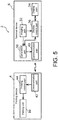
- FIG. 5 is a block diagram showing the functional configuration of the printing system 2 according to the first embodiment.
- the terminal device 6 includes an imaging part 32, a display part 34, a display control part 36, a generation part 38, and a communication part 40 (an example of a transmission part).
- the imaging part 32 is a camera for capturing an image in front of the terminal device 6 as a subject.
- the imaging part 32 is, for example, a camera that uses a complementary metal oxide semiconductor (CMOS) image sensor or a charge coupled device (CCD) image sensor.
- CMOS complementary metal oxide semiconductor
- CCD charge coupled device
- the display part 34 is, for example, a liquid crystal panel, and displays various screens. Also, the display part 34 is also a touch panel that serves as a user interface that receives various instructions from the user.
- the display control part 36 controls display content of the display part 34. Specifically, the display control part 36 causes the display part 34 to display the image being captured by the imaging part 32 in real time. In addition, the display control part 36 causes the display part 34 to display a layout image (which will be described later) showing a layout of one or more nail tips 8 in a printable region defined by the frame member 24 based on layout information (which will be described later) when the generation part 38 generates the layout information. Other functions of the display control part 36 will be described later.
- the generation part 38 generates operation information indicating various user instructions received by the display part 34 that functions as a touch panel. Further, the generation part 38 generates print information indicating a layout of printing to be applied to one or a plurality of nail tips 8 in the printable region defined by the frame member 24 based on the image captured by the imaging part 32. The generation part 38 outputs the generated operation information and print information to the communication part 40.
- the communication part 40 wirelessly communicates with a communication part 42 of the printing device 4.
- the communication part 40 transmits, for example, the operation information and the print information generated by the generation part 38 to the communication part 42 of the printing device 4.
- the printing device 4 includes the communication part 42 (an example of an acquisition part), a print control part 44, and the printing unit 16. Also, since the printing unit 16 has already been described, the description thereof will be omitted here.
- the communication part 42 wirelessly communicates with the communication part 40 of the terminal device 6.
- the communication part 42 receives (acquires) the operation information and the print information transmitted from the communication part 40 of the terminal device 6, for example.
- the communication part 42 outputs the received operation information and print information to the print control part 44.
- the print control part 44 controls the printing unit 16 based on the operation information and the print information from the communication part 42. Specifically, based on the operation information and the print information from the communication part 42, the print control part 44 controls an ink discharge timing from the print head mounted on the carriage 30 and controls driving of each of the first drive mechanism and the second drive mechanism.
- FIG. 6 is a flowchart showing a flow of the printing procedure in the printing system 2 according to the first embodiment.
- FIG. 7 is a diagram showing an example of a camera screen 46 displayed on the terminal device 6 according to the first embodiment when an imaging angle of the imaging part 32 is normal.
- FIG. 8A is a diagram showing an example of the camera screen 46 displayed on the terminal device 6 according to the first embodiment when the imaging angle of the imaging part 32 is slightly defective.
- FIG. 8B is a diagram showing an example of the camera screen 46 displayed on the terminal device 6 according to the first embodiment when the imaging angle of the imaging part 32 is defective.
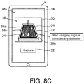
- FIG. 8C is a diagram showing an example of the camera screen 46 displayed on the terminal device 6 according to the first embodiment when the imaging angle of the imaging part 32 is considerably defective.
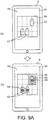
- FIG. 9A is a diagram showing an example of a print preview screen 58 displayed on the terminal device 6 according to the first embodiment.
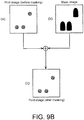
- FIG. 9B is a conceptual diagram for explaining a process of the generation part 38 of the terminal device 6 according to the first embodiment.
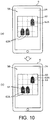
- FIG. 10 is a diagram showing another example of the print preview screen 58 displayed on the terminal device 6 according to the first embodiment.
- FIG. 11 is a diagram for explaining an example of a print result in the printing system 2 according to the first embodiment.
- the user slides the cassette 12 of the printing device 4 from the received position to the pulled-out position, and then removes the tray 14 from the cassette 12 to thereby take out the tray 14 from the inside of the housing 10 (S101).
- the user places one or a plurality of nail tips 8 to be printed on any of the plurality of placing tables 28a to 28e of the tray 14 (S102).
- S102 the user places three nail tips 8 on, for example, three placing tables 28b to 28d among the plurality of placing tables 28a to 28e of the tray 14 will be described.
- surfaces of the nail tips 8 placed on the tray 14 are configured to have white colors in advance.
- the user captures an image of the tray 14 and the three nail tips 8 placed on the tray 14 from above using the imaging part 32 of the terminal device 6 (S103).
- the display control part 36 of the terminal device 6 causes the display part 34 to display the camera screen 46.
- the camera screen 46 includes a camera window 50 for displaying the image 48 being captured by the imaging part 32 in real time, and a capture button 52 for capturing the image 48 currently displayed on the camera window 50 as a still image.
- the display control part 36 causes the camera window 50 to display a guide frame line 54.
- the guide frame line 54 is a frame line for guiding the user such that the frame member 24 included in the image 48 is displayed in the entire outer frame of the camera window 50.
- the guide frame line 54 is, for example, a rectangular red frame line and is displayed along the outer frame of the camera window 50.
- the display control part 36 switches the guide frame line 54 from display to non-display.
- the display control part 36 causes the camera window 50 to display a notification frame line 56 (an example of a notification display).
- the notification frame line 56 is a frame line for notifying the user whether the imaging angle of the imaging part 32 of the terminal device 6 is normal or not.
- the notification frame line 56 is, for example, a rectangular frame line and is displayed to be superimposed on the frame member 24 included in the image 48.
- the display control part 36 changes a color of the notification frame line 56 in accordance with the imaging angle of the imaging part 32 of the terminal device 6. Specifically, as shown in (b) of FIG. 7 , the display control part 36 determines whether the imaging angle of the imaging part 32 of the terminal device 6 is normal or not, for example, based on an absolute value (
- ) of the difference is equal to or more than 0 and less than a first threshold, and thus the display control part 36 determines that the imaging angle of the imaging part 32 of the terminal device 6 is normal.
- the display control part 36 sets the color of the notification frame line 56 to be green, which indicates that the imaging angle of the imaging part 32 of the terminal device 6 is normal.
- ) of the difference is equal to or more than the first threshold and less than a second threshold, and thus the display control part 36 determines that the imaging angle of the imaging part 32 of the terminal device 6 is slightly defective.
- the display control part 36 sets the color of the notification frame line 56 to be yellow, which indicates that the imaging angle of the imaging part 32 is slightly defective.
- ) of the difference is equal to or greater than the second threshold and less than a third threshold, and thus the display control part 36 determines that the imaging angle of the imaging part 32 of the terminal device 6 is defective.
- the display control part 36 sets the color of the notification frame line 56 to be brown, which indicates that the imaging angle of the imaging part 32 is defective.
- ) of the difference is equal to or greater than the third threshold value and less than a fourth threshold, and thus the display control part 36 determines that the imaging angle of the imaging part 32 of the terminal device 6 is considerably defective.
- the display control part 36 sets the color of the notification frame line 56 to be red, which indicates that the imaging angle of the imaging part 32 is considerably defective.
- the user can recognize that the imaging angle of the imaging part 32 of the terminal device 6 is not normal and can appropriately adjust the imaging angle of the imaging part 32 of the terminal device 6 so that the color of the notification frame line 56 changes to be green.
- notification frame line 56 has been described as a rectangular frame line in the present embodiment, it is not limited thereto, and may be, for example, a) four marks such as circles, which are respectively superimposed on four corners of the frame member 24 included in the image 48, b) a straight line connecting any four points on the frame member 24 included in the image 48 to each other, c) a specific color (for example, translucent white) having a specific transparency displayed in a region outside the frame member 24 included in the image 48, etc.
- a specific color for example, translucent white
- the user operates (taps) the capture button 52 in the state in which the color of the notification frame line 56 is green, whereby the display control part 36 captures the image 48 currently displayed in the camera window 50 as a still image.
- the display control part 36 outputs the captured image 48 to the generation part 38.
- the image 48 has been captured as a still image in the present embodiment, it is not limited thereto, and for example, the image 48 may be captured as a video, and an optimum still image may be selected from the captured video.
- the generation part 38 generates the layout information indicating the layout of the three nail tips 8 in the printable region defined by the frame member 24 included in the image 48 (S104) by executing, for example, perspective conversion processing on the image 48 from the display control part 36. At this time, the generation part 38 recognizes the printable region based on a contrast between the end surface 24b of the frame member 24 included in the image 48 and the placing member 22 included in the image 48. Further, the generation part 38 recognizes the layout of the three nail tips 8 in the printable region based on a contrast between the three nail tips 8 included in the image 48 and the placing member 22 included in the image 48. The generation part 38 outputs the generated layout information to the display control part 36 and the communication part 40. The display control part 36 causes the display part 34 to display the print preview screen 58 based on the layout information from the generation part 38 (S105).
- the placing member 22 is formed in black, and thus even when the ink discharged from the ink head adheres to the placing member 22, ink stains on the placing member 22 are hardly noticeable and hardly affect the contrast described above.
- the print preview screen 58 includes a layout image 60 showing the layout of one or more nail tips 8 in the printable region defined by the frame member 24.
- An outer frame of the layout image 60 indicates a range of the printable region defined by the inner peripheral surface of the frame member 24.
- the layout image 60 includes nail tip images 62 (an example of a recording medium image) showing the nail tips 8.
- the layout image 60 shows the layout in which three nail tips 8 are placed on the placing tables 28b to 28d in the printable region.
- the user operates the terminal device 6 such that a type of the design to be printed on the nail tips 8 is selected and a design image 64 showing the selected design is dragged and superimposed on the nail tip images 62 on the print preview screen 58.
- the display control part 36 causes the design image 64 in the layout image 60 to be superimposed and displayed on the nail tip images 62 (SI06).
- the display control part 36 displays the nail tip images 62 in original colors (colors before printing) of the nail tips 8 in the layout image 60 and displays the design image 64 in an actual print color of the design.
- the display control part 36 displays the nail tip images 62 in white and the design image 64 in yellow.
- the display control part 36 performs a masking process of masking a region of the design image 64 projecting outside the nail tip image 62. That is, as shown in (b) of FIG. 9A , in the case in which an original size of the design image 64 (shown by dashed frame lines in (b) of FIG. 9A ) is larger than a size of the nail tip image 62, the display control part 36 masks the region (shown by diagonal lines in (b) of FIG. 9A ) projecting outside a contour of the nail tip image 62 in the design image 64 through the masking process.
- wasteful discharge of ink from the ink head toward the region outside the nail tip 8 can be inhibited during printing, and wasteful consumption of ink can be inhibited. Further, it is possible to prevent the tray 14 from being unnecessarily soiled due to the ink from the ink head adhering to the tray 14.
- the generation part 38 generates print information indicating a layout of printing to be applied to the nail tips 8 based on the design image 64 superimposed on the nail tip images 62 and outputs the generated print information to the communication part 40.
- the generation part 38 generates a print image shown in (a) of FIG. 9B based on the design image 64 superimposed on the nail tip images 62.
- the generation part 38 generates a mask image having contours of the nail tips 8 disposed in the printable region as shown in (b) of FIG. 9B by binarizing the image 48 and detecting the layout of the nail tips 8.
- the generation part 38 performs the masking process (that is, masking the region outside the mask image in the design image 64 described above) on the print image shown in (a) of FIG. 9B with the mask image shown in (b) of FIG. 9B , thereby generating the print image as shown in (c) of FIG. 9B as the print information. That is, the print information is information indicating how to dispose one or a plurality of design images 64 in the printable region.
- the yellow ink of the printed design is mixed with the blue color of the nail tip 8 and becomes green.
- a color (for example, green) of the design actually printed on the nail tip 8 is different from a color (for example, yellow) of the design image 64 displayed on the print preview screen 58, the user may feel uneasy. Therefore, as shown in (a) and (b) of FIG.
- the display control part 36 synthesizes pixels using a subtractive color method in the design image 64 (for example, yellow) superimposed on a nail tip image 62A (for example, blue) in the layout image 60.
- a subtractive color method in the design image 64 for example, yellow
- a nail tip image 62A for example, blue
- the color of the design image 64 becomes the same color as the color of the design actually printed on the nail tip 8 (for example, green), it is possible to prevent the user from feeling uneasy.
- the user attaches the tray 14 to the upper surface of the cassette 12 and slides the cassette 12 from the pulled-out position to the received position to set the tray 14 inside the housing 10 (S107). Then, the user operates the terminal device 6 to instruct execution of printing, and thus the communication part 40 of the terminal device 6 transmits the operation information and the print information to the communication part 42 of the printing device 4 (S108).
- the print control part 44 recognizes the layout of the three nail tips 8 in the printable region and the design to be printed on each nail tip 8 based on the operation information and the print information from the communication part 42 and controls the printing unit 16. As a result, as shown in FIG. 11 , the printing unit 16 prints the design 66 corresponding to the design image 64 on the three nail tips 8 placed on the placing tables 28b to 28d (S109).
- the generation part 38 of the terminal device 6 generates the print information indicating the layout of printing to be applied to the nail tips 8 in the printable region defined by the frame member 24 based on the image 48 including the nail tips 8 and the frame member 24 disposed to surround the nail tips 8.
- the print control part 44 of the printing device 4 acquires the print information from the terminal device 6 and controls the printing unit 16 based on the acquired print information.
- the print control part 44 of the printing device can recognize the layout of printing to be applied to the nail tips 8 placed on the tray 14.
- the printing device 4 it is possible to perform printing on the nail tip 8 placed on an arbitrary placing table with high accuracy.
- FIG. 12 is a diagram for explaining printing in the printing system 100 according to the comparative example.
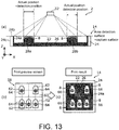
- FIG. 13 is a diagram for explaining printing in the printing system 2 according to the first embodiment. Also, in FIG. 12 , the same components as those of the first embodiment are denoted by the same reference numerals, and descriptions thereof will be omitted.
- the tray 102 has only the placing member 22 and does not have the frame member. For that reason, in the case in which the imaging part 32 captures an image including the placing member 22 and the nail tips 8 placed on the placing member 22, the generation part 38 recognizes the upper surface of the base 26 as a surface detected as the printable region (hereinafter, referred to as a "capture surface") based on a position of the outer peripheral part of the base 26 of the placing member 22 included in the image.
- a capture surface a surface detected as the printable region
- a height position of a surface defined by an upper end of the nail tip 8 placed on the placing member 22 shifts upward (to the plus side of the Z axis) with respect to a height position of the capture surface.
- a horizontal position (a position in the XY plane) of the nail tip 8 included in the image detected by the generation part 38 becomes a position displaced from an actual horizontal position of the nail tip 8.
- the design image 64 is disposed in a central part of the nail tip image 62 on the print preview screen 58 as shown in (b) of FIG. 12
- the design 66 is printed at a position displaced from a central part of the nail tip 8 in an actual print result as shown in (c) of FIG. 12 .
- the tray 14 has the frame member 24 in addition to the placing member 22.
- the inner peripheral surface of the frame member 24 is formed in black, like the placing member 22.
- the generation part 38 recognizes the surface defined by the end surface 24b of the frame member 24 as the capture surface based on the position of the upper end of the inner peripheral surface of the frame member 24 included in the image.
- the height position of the area detection surface is the same as the height position of the capture surface.
- the horizontal position of the nail tip 8 included in the image detected by the generation part 38 is the same as the actual horizontal position of the nail tip 8.
- the design image 64 is disposed in the central part of the nail tip image 62 on the print preview screen 58 as shown in (b) of FIG. 13 , the pattern 66 is printed on the central part of the nail tip 8 even in the actual print result as shown in (c) of FIG. 13 . Therefore, the design 66 can be accurately printed on the nail tip 8.
- the generation part 38 may correct the height position of the capture surface to the height position of the area detection surface based on the information.
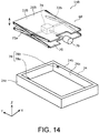
- FIG. 14 is an exploded perspective view showing the tray 14B according to the second embodiment.
- FIG. 15 is a cross-sectional view of the tray 14B according to the second embodiment. Also, in each of the following embodiments, the same components as those in the first embodiment are denoted by the same reference numerals, and descriptions thereof will be omitted.
- the tray 14B has a lifting mechanism 68 for moving a placing member 22B up and down in the vertical direction (Z axis direction) with respect to the frame member 24. Also, for the convenience of explanation, in FIG. 14 , illustration of the plurality of placing tables 28a to 28e of the placing member 22B is omitted, and in FIG. 15 , illustration of the lifting mechanism 68 (excluding a base part 70) is omitted.
- the lifting mechanism 68 has the base part 70, a pair of link mechanisms 72a and 72b, a drive mechanism 74, a drive source 76, and an upper limit sensor 78.
- the base part 70 is formed in a substantially rectangular plate shape in an XY plan view and is disposed to face a lower surface of a base 26B of the placing member 22B.
- the base part 70 is fixed to a lower end part of the inner peripheral surface 24a of the frame member 24.
- the pair of link mechanisms 72a and 72b are pantograph-like mechanisms that connect the base part 70 to the base 26B and are disposed to face each other.
- the drive mechanism 74 moves the base 26B up and down with respect to the base part 70 by extending and contracting the pair of link mechanisms 72a and 72b.
- the drive source 76 is a motor for driving the drive mechanism 74.
- the upper limit sensor 78 is configured of, for example, a transmissive photo sensor and has a light emitting element 78a and a light receiving element 78b.
- the light emitting element 78a and the light receiving element 78b are disposed to face each other at an upper end part of the inner peripheral surface 24a of the frame member 24.
- the print control part 44 drives the drive source 76 based on a detection signal from the upper limit sensor 78.
- the drive mechanism 74 moves the base 26B up with respect to the base part 70.
- the print control part 44 stops driving the drive source 76 based on the detection signal from the upper limit sensor 78.
- the drive mechanism 74 stops lifting of the base 26B at a timing when a height position of the upper end of the nail tip 8 becomes the same height position as the height position of the end surface 24b of the frame member 24.
- the lifting mechanism 68 can position the height position of the upper end of the nail tip 8 at the same height position as the height position of the end surface 24b of the frame member 24.
- the drive mechanism 76 is driven by the drive source 76 in the present embodiment, it is not limited thereto, and the drive mechanism 74 may be manually driven by the user.
- the drive source 76 may be omitted, and a plate-shaped spacer may be inserted between the base 26B of the placing member 22B and the base part 70, thereby adjusting the height position of the upper end of the nail tip 8.
- FIG. 16 is a perspective view showing the printing device 4C according to the third embodiment.
- a structure of a tray 14C is different from that of the first embodiment.
- a frame member 24C of the tray 14C is formed in a rectangular plate shape in an XY plan view.
- a rectangular recessed part 80 is formed on an upper surface of the frame member 24C in an XY plan view.
- the base 26 of the placing member 22 is supported on a bottom part of the recessed part 80.
- An inner peripheral surface of the recessed part 80 is disposed along the outer peripheral part of the upper surface of the base 26 of the placing member 22. That is, the inner peripheral surface of the recessed part 80 is disposed to rise from the outer peripheral part of the upper surface of the base 26 of the placing member 22 and is disposed to surround one or a plurality of nail tips 8 placed on the placing member 22.
- FIG. 17A is a perspective view schematically showing the printing device 4D according to the fourth embodiment.
- FIG. 17B is a cross-sectional view of a main part of a tray 14D according to the fourth embodiment along line XVII-XVII in FIG. 17A .
- a structure of the tray 14D is different from that of the first embodiment.
- the tray 14D has a placing member 22D and a frame member 24D.
- the placing member 22D also has a function as the cassette 12 described in the first embodiment. That is, the placing member 22D is slidable between the received position and the pulled-out position.
- the placing member 22D includes a base 26D, a wall part 82, and a placing part 86.
- the wall part 82 is formed in a substantially U shape in an XY plan view and is disposed to rise from an outer peripheral part of the base 26D.
- a front side of the wall part 82 (the minus side of the Y axis) is open.
- the wall part 82 has a side wall part 82a extending in the left to right direction (X axis direction), and a pair of side wall parts 82b and 82c extending in parallel with each other from both end parts of the side wall part 82a in a longitudinal direction thereof toward the front side (the minus side of the Y axis).
- a U-shaped recessed part 84 in an XY plan view is formed in each inner peripheral part of the side wall parts 82a, 82b, and 82c.
- a placing part 86 is formed on each inner peripheral part of the side wall parts 82a, 82b, and 82c by the recessed part 84.
- abutting parts 88 and 90 are respectively formed at end parts of the pair of side wall part 82b and 82c on the front side by the recessed part 84.
- the placing member 22D is formed, for example, in black. Also, for the convenience of explanation, in FIG. 17A , expression of the black color of the placing member 22D is replaced with a gray color.
- the frame member 24D is formed in a U shape in an XY plan view and is detachably supported by the placing member 22D.
- the front side (minus side of the Y axis) of the frame member 24D is open.
- widths p, q, and r of the frame member 24D may be the same or different from each other.
- the frame member 24D is supported by the placing part 86 of the placing member 22D.
- an outer peripheral surface 24Dc (see FIG. 17B ) of the frame member 24D is covered with the side wall parts 82a, 82b, and 82c.
- both end parts of the frame member 24D on the open side are covered with the abutting parts 88 and 90 of the placing member 22D, respectively.
- an outer peripheral part of an end surface 24Db of the frame member 24D is covered with the side wall parts 82a, 82b, and 82c (including the abutting parts 88 and 90) in an XY plan view.
- a height position of the end surface 24Db of the frame member 24D is the same as a height position of each upper surface of the side wall parts 82a, 82b, and 82c of the placing member 22D.
- an inner peripheral surface 24Da of the frame member 24D is exposed to the outside.
- the inner peripheral surface 24Da of the frame member 24D is configured to have the same color as that of the placing member 22D, that is, in black.
- the end surface 24Db of the frame member 24D is configured to have a color different from the color of the placing member 22D, for example, in white.
- a U-shaped region having a predetermined width for example, a width of about 3 mm
- expression of the black color of the inner peripheral surface 24Da of the frame member 24D is replaced with a gray color.
- FIG. 17C is a cross-sectional view of a main part of a tray 14E according to a modified example of the fourth embodiment.
- a U-shaped groove part 92 in an XY plan view is formed on each upper surface of the side wall parts 82a, 82b, and 82c of a wall part 82E of a placing member 22E.
- the frame member 24D is fitted in the groove part 92.
- the inner peripheral surface 24Da of the frame member 24D is covered by an inner peripheral surface of the groove part 92.
- FIG. 18 is a diagram for explaining the method of calculating the printable region according to the fourth embodiment.
- the display control part 36 (see FIG. 5 ) of the terminal device 6 recognizes all white regions (including the U-shaped region of the end surface 24Db of the frame member 24D) by binarizing the captured image.
- the display control part 36 performs Convex Hull processing (an example of predetermined image processing) on all the white regions recognized as described above, thereby converting all the white regions into a predetermined region.
- Convex Hull processing an example of predetermined image processing
- the U-shaped region of the end surface 24Db of the frame member 24D is converted into a rectangular region by complementing one open side of the U-shaped region.
- the display control part 36 narrows down only the region that satisfies all of the following three conditions, that is, a) 50% or more of a total area of the captured image is occupied, b) the number of vertices is 4, and c) the aspect ratio is close to the frame member 24D, from the regions converted as described above. Further, in the case in which the printable region from the captured image is cut off, recognition quality is reduced, and it is not suitable as the captured image, and thus, in order to recognize the capture operation as an error, it may narrow down only the region on the condition of d) not being adjacent to four sides around the captured image itself. As a result, the display control part 36 recognizes the U-shaped frame member 24D as a square frame member.
- the display control part 36 perspective-transforms the region narrowed down as described above into a size (w ⁇ h) of the frame member 24D.
- the display control part 36 determines, as the printable region (the hatched region in FIG. 18 ), a range excluding the regions a, b, c, and d of the frame member 24D from the perspective-transformed image.
- the front side of the frame member 24D is open.
- the user can place a print target (an example of the recording medium) such as the nail tip 8 on the placing member 22D through the front side of the frame member 24D.
- a print target an example of the recording medium
- the frame member 24D is removed from the placing member 22D, so that the print target can be easily taken out from the placing member 22D.
- the display control part 36 can easily determine the orientations of the frame member 24D and the placing member 22D.
- the U-shaped region having a predetermined width (for example, a width of about 3 mm) from the edge of the end surface 24Db of the frame member 24D on the inner peripheral surface 24Da side is formed in black.
- the height position of the end surface 24Db of the frame member 24D is the same as the height position of each upper surface of the side wall parts 82a, 82b, and 82c of the placing member 22D.
- the height position of the area detection surface can be set to the same height position as the height position of the capture surface, similar to that described in the first embodiment. As a result, printing accuracy can be improved.
- FIG. 19 is a diagram for explaining another method of calculating the printable region.
- the display control part 36 of the terminal device 6 recognizes all white regions (including the U-shaped region of the end surface 24Db of the frame member 24D) by binarizing the captured image.
- the display control part 36 narrows down the U-shaped region of the end surface 24Db of the frame member 24D as a region having eight vertices.
- the display control part 36 leaves four outer vertices out of the above-described eight vertices and complements the one open side of the U-shaped region to convert the region into a rectangular region.
- the display control part 36 recognizes the U-shaped frame member 24D as a square frame member.
- the display control part 36 narrows down the rectangular region converted as described above in the case in which the rectangular region satisfies all of the following three conditions, that is, a) 50% or more of a total area of the captured image is occupied, b) the number of vertices is 4, and c) the aspect ratio is close to the frame member 24D. Further, in the case in which the printable region from the captured image is cut off, recognition quality is reduced, and it is not suitable as the captured image, and thus, in order to recognize the capture operation as an error, it may narrow down only the region on the condition of d) not being adjacent to four sides around the captured image itself.
- the display control part 36 perspective-transforms the rectangular region narrowed down as described above into a size (w ⁇ h) of the frame member 24D.
- the display control part 36 determines, as the printable region, a range excluding the regions a, b, c, and d (see FIG. 18 ) of the frame member 24D from the perspective-transformed image.
- the printing method of the printing unit 16 is the ink jet method in each of the above embodiments, the printing method is not limited thereto, and other printing methods may be adopted.
- the placing member 22 (22B, 22D, and 22E) and the inner peripheral surface 24a (24Da) of the frame member 24 (24C and 24D) are each formed in black and the end surface 24b (24Db) and the outer peripheral surface 24c of the frame member 24 (24C and 24D) are formed in white in each of the above embodiments, the invention is not limited thereto, and for example, they may be configured to have different colors which are in a complementary color relationship, or may be configured to have colors in the range having different component values when color components used for discrimination are extracted.
- the information processing device is configured by the terminal device 6 in each of the above-described embodiments, the invention is not limited thereto, and the information processing device may be configured by a server, for example. In this case, for example, by transmitting an image captured by an imaging part of a mobile terminal to the server, the server generates the print information based on the received image.
- the nail tip 8 is adopted as the recording medium to be printed by the printing device 4 (4C and 4D) in each of the above-described embodiments, the invention is not limited thereto, and for example, an arbitrary three-dimensional object such as a smartphone case and a golf ball may be adopted as the recording medium.
- the imaging part 32 of the terminal device 6 is configured to capture the image in each of the above embodiments, the invention is not limited thereto, and the image may be captured by an imaging part disposed inside the housing 10 of the printing device 4 (4C and 4D).
- the tray 14 (14B, 14C, 14D, and 14E) may be omitted, and a member corresponding to the frame member 24 (24C and 24D) may be disposed inside the housing 10 of the printing device 4 (4C and 4D).
- the terminal device 6 is configured to have the display control part 36 and the generation part 38 in each of the above embodiments, the invention is not limited thereto, and the printing device 4 (4C and 4D) may be configured to perform the processes of the display control part 36 and the generation part 38. Alternatively, the printing device 4 (4C and 4D) and the terminal device 6 may be configured to perform the processes of the display control part 36 and the generation part 38 together.
- the invention can be applied as a printing device or the like for printing nail tips, for example.
Landscapes
- Engineering & Computer Science (AREA)
- Signal Processing (AREA)
- Multimedia (AREA)
- Human Computer Interaction (AREA)
- General Engineering & Computer Science (AREA)
- Theoretical Computer Science (AREA)
- Computer Networks & Wireless Communication (AREA)
- Physics & Mathematics (AREA)
- General Physics & Mathematics (AREA)
- Manufacturing & Machinery (AREA)
- Quality & Reliability (AREA)
- Computing Systems (AREA)
- Accessory Devices And Overall Control Thereof (AREA)
- Ink Jet (AREA)
- Editing Of Facsimile Originals (AREA)
- Controls And Circuits For Display Device (AREA)
Abstract
Description
- The disclosure relates to a printing device for performing printing on a recording medium, and an information processing device which can communicate with the printing device.
- For example, a printing device for printing a three-dimensional object such as a nail tip (a so-called artificial nail) is known (for example, see Patent Document 1). A conventional printing device includes a tray for placing a three-dimensional object thereon, and a print head for performing printing on the three-dimensional object on the tray. The print head ejects ink toward a surface of the three-dimensional object placed at a predetermined position on the tray while reciprocating in a predetermined direction with respect to the tray.
- [Patent Document 1] Japanese Patent Laid-Open No.
2003-226760 - In the conventional printing device described above, in the case in which a user places the three-dimensional object at an arbitrary position on the tray, there is a concern that the printing device may not be able to recognize a layout of the three-dimensional object on the tray. For that reason, there is a problem that printing on the three-dimensional object with high accuracy is difficult.
- The disclosure is intended to solve the above problems, and provides a printing device and an information processing device in which printing on a recording medium can be performed with high accuracy.
- In order to achieve the above object, a printing device according to one aspect of the disclosure is a printing device for performing printing on a recording medium and includes: a frame member disposed to surround the recording medium; a printing part that performs printing on the recording medium surrounded by the frame member; an acquisition part that acquires print information which is generated based on an image obtained by capturing the frame member and the recording medium and indicates a layout of printing to be applied to the recording medium in a printable region defined by the frame member; and a print control part that controls the print part based on the acquired print information.
- According to the present aspect, since the print control part controls the print part based on the print information indicating the layout of printing to be applied to the recording medium in the printable region defined by the frame member, the print control part can recognize the layout of printing to be applied to the recording medium based on the print information, for example, even in the case in which a user places the recording medium at an arbitrary position. As a result, printing on the recording medium can be performed with high accuracy.
- For example, the printing device according to one aspect of the invention may be further include a placing member having a placing surface on which the recording medium is placed, the frame member may be disposed along an outer peripheral part of the placing surface of the placing member, and the placing surface of the placing member and an end surface of the frame member may have different colors in a plan view.
- According to the present aspect, since the placing surface of the placing member and the end surface of the frame member have different colors in a plan view, the printable region defined by the frame member can be accurately recognized based on the contrast between the placing surface of the placing member and the end surface of the frame member in an image obtained by capturing the frame member and the recording medium.
- For example, the printing device according to one aspect of the invention may be configured such that the frame member is disposed to rise from the outer peripheral part of the placing surface of the placing member, and an inner peripheral surface of the frame member may have the same color as the placing surface of the placing member.
- According to present aspect, a height position of a surface detected as the printable region (a surface defined by the end surface of the frame member) and a height position of a surface defined by the recording medium placed on the placing member can be matched with each other. As a result, print deviation on the recording medium can be inhibited.
- For example, the printing device according to one aspect of the invention may further include a lifting mechanism for elevating the placing member with respect to the frame member.
- According to the present aspect, the placing member is moved up and down with respect to the frame member by the lifting mechanism in accordance with a size of the recording medium, or the like, so that a height position of the recording medium placed on the placing member can be positioned at a height position of the end surface of the frame member. As a result, the height position of the surface detected as the printable region (the surface defined by the end surface of the frame member) and the height position of the surface defined by the recording medium placed on the placing member can be easily matched with each other.
- For example, the printing device according to one aspect of the invention may be configured such that the placing surface of the placing member is formed in black, and the end surface of the frame member is formed in white.
- According to the present aspect, the contrast between the placing surface of the placing member and the end surface of the frame member in the image obtained by capturing the frame member and the recording medium can be made clearer.
- An information processing device according to one aspect of the invention is an information processing device which can communicate with a printing device for performing printing on a recording medium, and includes: an imaging part that captures an image including the recording medium and a frame member disposed to surround the recording medium; a generation part that generates print information indicating a layout of printing to be applied to the recording medium in a printable region defined by the frame member based on the image captured by the imaging part; and a transmission part that transmits the generated print information to the printing device.
- According to the present aspect, since the transmission part transmits the print information indicating the layout of printing to be applied to the recording medium in the printable region defined by the frame member to the printing device, the printing device can recognize the layout of printing to be applied to the recording medium based on the print information from the information processing device, for example, even in the case in which a user places the recording medium at an arbitrary position in the printing device. As a result, printing on the recording medium can be performed with high accuracy in the printing device.
- For example, the information processing device according to one aspect of the invention may further include a display part, and a display control part that displays the image captured by the imaging part on the display part, the generation part may further generate layout information indicating a layout of the recording medium in the printable region based on the image captured by the imaging part, and the display control part may cause the display part to display a layout image indicating the layout of the recording medium in the printable region based on the layout information when the layout information is generated by the generation part.
- According to the present aspect, since the display control part causes the display part to display the layout image indicating the layout of the recording medium in the printable region, the user can use the layout image displayed on the display part as a print preview screen.
- For example, the information processing device according to one aspect of the invention may be configured such that the display control part further displays, in the layout image, a design image showing a design to be printed on the recording medium by superimposing the design image on a recording medium image showing the recording medium, and the generation part generates the print information based on the design image superimposed on the recording medium image.
- According to the present aspect, since the display control part superimposes and displays the design image on the recording medium image in the layout image, the user can easily recognize a print image of the recording medium on which the design has been printed.
- For example, the information processing device according to one aspect of the invention may be configured such that the display control part further synthesizes pixels in the layout image using a subtractive color method in the design image superimposed on the recording medium image.
- According to the present aspect, when the user views the layout image displayed on the display part as the print preview screen, by making a color of the design image in the layout image the same as a color of the design actually printed on the recording medium, it is possible to prevent the user from feeling uneasy.
- For example, the information processing device according to one aspect of the invention may be configured such that the display control part further performs a masking process of masking a region of the design image projecting outside the recording medium image when the design image is displayed to be superimposed on the recording medium image in the layout image.
- According to the present aspect, by masking the region of the design image projecting outside the recording medium image through the masking process, wasteful printing is not performed in the projecting region so that wasteful consumption of ink or the like can be inhibited, and it is possible to prevent components (for example, a tray and the like) of the printing device from being unnecessarily soiled with ink.
- For example, the information processing device according to one aspect of the invention may be configured such that the display control part further causes a notification display to be superimposed and displayed on the frame member included in the image and changes a color of the notification display in accordance with an imaging angle of the imaging part when the image captured by the imaging part is being displayed on the display part.
- According to the present aspect, by changing the color of the notification display in accordance with the imaging angle of the imaging part, the user can be urged to adjust the imaging angle of the imaging part to an appropriate imaging angle.
- For example, the information processing device according to one aspect of the invention may be configured such that the frame member is formed in a U shape, and the display control part further performs predetermined image processing on an image obtained by capturing the U-shaped frame member to complement the frame member so that the frame member is recognized as a rectangular shape.
- According to the present aspect, since the frame member is formed in a U shape, the recording medium can be easily taken out. Further, since the display control part performs the predetermined image processing on the image obtained by capturing the U-shaped frame member to complement the frame member to be recognized as a square shape, the printable region can be easily determined.
- According to the printing device and the like according to one aspect of the invention, it is possible to perform printing on the recording medium with high accuracy.
-
-
FIG. 1 is a perspective view showing a printing system according to a first embodiment. -
FIG. 2 is a perspective view showing an internal structure of the printing device according to the first embodiment. -
FIG. 3 is a perspective view showing an extracted state of a tray of the printing device according to the first embodiment. -
FIG. 4 is a cross-sectional view of the tray of the printing device according to the first embodiment along line IV-IV inFIG. 3 . -
FIG. 5 is a block diagram showing a functional configuration of the printing system according to the first embodiment. -
FIG. 6 is a flowchart showing a flow of a printing procedure in the printing system according to the first embodiment. -
FIG. 7 is a diagram showing an example of a camera screen displayed on a terminal device according to the first embodiment in a case in which an imaging angle by an imaging part is normal. -
FIG. 8A is a diagram showing an example of the camera screen displayed on the terminal device according to the first embodiment in a case in which the imaging angle by the imaging part is slightly defective. -
FIG. 8B is a diagram showing an example of the camera screen displayed on the terminal device according to the first embodiment in a case in which the imaging angle by the imaging part is defective. -
FIG. 8C is a diagram showing an example of the camera screen displayed on the terminal device according to the first embodiment in a case in which the imaging angle by the imaging part is considerably defective. -
FIG. 9A is a diagram showing an example of a print preview screen displayed on the terminal device according to the first embodiment. -
FIG. 9B is a conceptual diagram for explaining a process of a generation part of the terminal device according to the first embodiment. -
FIG. 10 is a diagram showing another example of the print preview screen displayed on the terminal device according to the first embodiment. -
FIG. 11 is a diagram for explaining an example of a print result in the printing system according to the first embodiment. -
FIG. 12 is a diagram for explaining printing in a printing system according to a comparative example. -
FIG. 13 is a diagram for explaining printing in the printing system according to the first embodiment. -
FIG. 14 is an exploded perspective view showing a tray according to a second embodiment. -
FIG. 15 is a cross-sectional view of the tray according to the second embodiment. -
FIG. 16 is a perspective view showing a printing device according to a third embodiment. -
FIG. 17A is a perspective view schematically showing a printing device according to a fourth embodiment. -
FIG. 17B is a cross-sectional view of a main part of a tray according to the fourth embodiment along line XVII-XVII inFIG. 17A . -
FIG. 17C is cross-sectional view of a main part of a tray according to a modified example of the fourth embodiment. -
FIG. 18 is a diagram for explaining a method of calculating a printable region according to the fourth embodiment. -
FIG. 19 is a diagram for explaining another method of calculating the printable region. - Hereinafter, embodiments of the invention will be described in detail with reference to the drawings. Also, the embodiments described below all show comprehensive or specific examples. Numerical values, shapes, materials, constituent elements, layout positions and connected forms of the constituent elements, and the like shown in the following embodiments are examples, and are not intended to limit the invention. Further, among the constituent elements in the following embodiments, constituent elements not described in independent claims are described as arbitrary constituent elements.
- First, an outline of a
printing system 2 according to a first embodiment will be described with reference toFIG. 1. FIG. 1 is a perspective view showing aprinting system 2 according to the first embodiment. Also, inFIG. 1 and the like, a width direction (a left to right direction) of aprinting device 4 is defined as an X axis direction, a depth direction (a front to rear direction) of theprinting device 4 is defined as a Y axis direction, and a height direction (a vertical direction) of theprinting device 4 is defined as a Z axis direction. - As shown in
FIG. 1 , theprinting system 2 includes theprinting device 4 and a terminal device 6 (an example of an information processing device). - The
printing device 4 is, for example, an inkjet printer for printing a design on a nail tip 8 (an example of a recording medium). Also, in the present specification, the design indicates a concept including, for example, a figure, a pattern, a shape, a color and the like. - The
terminal device 6 is a mobile terminal such as a smartphone or a tablet terminal. Theterminal device 6 can wirelessly communicate with theprinting device 4 by Bluetooth (registered trademark) or the like, for example. A dedicated application for operating theprinting device 4 is installed in theterminal device 6. A user can operate theprinting device 4 by using the application installed in theterminal device 6 as a user interface. - Next, a structure of the
printing device 4 according to the first embodiment will be described with reference toFIGS. 1 to 4 .FIG. 2 is a perspective view showing an internal structure of theprinting device 4 according to the first embodiment.FIG. 3 is a perspective view showing an extracted state of atray 14 of theprinting device 4 according to the first embodiment.FIG. 4 is a cross-sectional view of thetray 14 of theprinting device 4 according to the first embodiment along line IV-IV inFIG. 3 . - As shown in
FIGS. 1 and2 , theprinting device 4 includes ahousing 10, acassette 12, thetray 14, and a printing unit 16 (an example of a printing part). - As shown in
FIG. 1 , thehousing 10 is formed in a box shape, for example. Anopening 18 for inserting thecassette 12 is formed on afront surface 10a of thehousing 10. Apower button 20 for turning power of theprinting device 4 on or off is disposed on atop surface 10b of thehousing 10. - As shown in
FIG. 1 , thecassette 12 is for putting thetray 14 into and taking it out of thehousing 10. Thecassette 12 is slidable between a received position (not shown) at which it is received inside thehousing 10 and a pulled-out position at which thehousing 10 is pulled out toward a front side (a minus side of the Y axis) through the opening 18 (seeFIG. 1 ). - As shown in
FIG. 1 , thetray 14 is for placing one or a plurality ofnail tips 8 and is detachably supported on an upper surface of thecassette 12. With thecassette 12 in the received position, thetray 14 is disposed in a printing region 21 (seeFIG. 2 ) inside thehousing 10. As shown inFIGS. 3 and 4 , thetray 14 has a placingmember 22 and aframe member 24. - As shown in
FIG. 3 , the placingmember 22 has abase 26 and a plurality of placing tables 28a, 28b, 28c, 28d, and 28e (28a to 28e). Thebase 26 is formed in a rectangular plate shape in an XY plan view. As shown inFIGS. 3 and 4 , each of the plurality of placing tables 28a to 28e is formed to protrude upward (a plus side of the Z axis) from an upper surface (an example of a placing surface) of thebase 26. The plurality ofnail tips 8 to be printed are each placed on the plurality of placing tables 28a to 28e. Each upper surface (an example of the placing surface) of the plurality of placing tables 28a to 28e is formed in a convex shape corresponding to a shape of thenail tip 8. A height position of each upper end of the plurality ofnail tips 8 placed on each of the plurality of placing tables 28a to 28e is the same height position as a height position of anend surface 24b of theframe member 24. The upper surface of thebase 26 and each of the plurality of placing tables 28a to 28e are formed in black, for example. Also, for the convenience of explanation, expression of the black color of the placingmember 22 is omitted inFIGS. 1 and2 , and the black color of the placingmember 22 is replaced with a gray color inFIG. 3 . In addition, in the present specification, the expression "formed in black (or white)" indicates a concept including all of a) a case of having been formed originally in black (or white), b) a case of being painted later in black (or white), and c) a case in which a black (or white) label or sheet is attached. - As shown in
FIG. 3 , theframe member 24 is formed in a rectangular tubular shape in an XY plan view and is disposed along an outer peripheral part of the upper surface of thebase 26 of the placingmember 22. Specifically, as shown inFIG. 4 , theframe member 24 is disposed to rise from the outer peripheral part of the upper surface of thebase 26 of the placingmember 22 and is disposed to surround one or a plurality ofnail tips 8 mounted on the placingmember 22. Also, in the present specification, "disposed to surround one or a plurality ofnail tips 8" does not indicate only a case in which the entire circumference of one or a plurality ofnail tips 8 is surrounded, but also indicates a case in which only a part of the entire circumference of one or a plurality ofnail tips 8 is surrounded. An innerperipheral surface 24a of theframe member 24 is formed in the same color as the placingmember 22, that is, in black. Also, in the present specification, "the same color" indicates a concept including not only exactly the same color but also similar colors. Further, theend surface 24b and an outerperipheral surface 24c of theframe member 24 in an axial direction (the Z axis direction) have a color different from the color of the placingmember 22, for example, in white. Also, for the convenience of explanation, expression of the black color of the innerperipheral surface 24a of theframe member 24 is omitted inFIGS. 1 and2 , and the black color of the innerperipheral surface 24a of theframe member 24 is replaced with a gray color inFIG. 3 . - As shown in
FIG. 2 , theprinting unit 16 is a part for printing the design on thenail tip 8 and is disposed inside thehousing 10. A printing method of theprinting unit 16 is an inkjet method in which printing is performed by spraying mist-like ink on thenail tip 8. Theprinting unit 16 has acarriage 30, a first drive mechanism (not shown), and a second drive mechanism (not shown). - An ink tank (not shown) and a print head (not shown) are mounted in the
carriage 30. The ink tank is filled with four types of ink, for example, CMYK (C: cyan, M: magenta, Y: yellow, K: black). The print head discharges each color of ink from the ink tank downward (toward a minus side of the Z axis). - The first drive mechanism is a mechanism for moving the
carriage 30 in the left to right direction (X axis direction). The second drive mechanism is a mechanism for moving thetray 14 in the front to rear direction (Y axis direction) in theprinting region 21. - When printing is performed, the first drive mechanism reciprocates the
carriage 30 in the left to right direction, and the second drive mechanism moves thetray 14 in theprinting region 21 from one side in the front to rear direction to the other side (from a plus side of the Y axis to the minus side). In this state, the ink from the print head mounted on thecarriage 30 is sprayed toward thetray 14 disposed in theprinting region 21, and thus printing is applied to one or a plurality ofnail tips 8 placed on thetray 14. - Next, a functional configuration of the
printing system 2 according to the first embodiment will be described with reference toFIG. 5. FIG. 5 is a block diagram showing the functional configuration of theprinting system 2 according to the first embodiment. - As illustrated in
FIG. 5 , theterminal device 6 includes animaging part 32, adisplay part 34, adisplay control part 36, ageneration part 38, and a communication part 40 (an example of a transmission part). - The
imaging part 32 is a camera for capturing an image in front of theterminal device 6 as a subject. Theimaging part 32 is, for example, a camera that uses a complementary metal oxide semiconductor (CMOS) image sensor or a charge coupled device (CCD) image sensor. Theimaging part 32 outputs the captured image to each of thedisplay control part 36 and thegeneration part 38. - The
display part 34 is, for example, a liquid crystal panel, and displays various screens. Also, thedisplay part 34 is also a touch panel that serves as a user interface that receives various instructions from the user. - The
display control part 36 controls display content of thedisplay part 34. Specifically, thedisplay control part 36 causes thedisplay part 34 to display the image being captured by theimaging part 32 in real time. In addition, thedisplay control part 36 causes thedisplay part 34 to display a layout image (which will be described later) showing a layout of one ormore nail tips 8 in a printable region defined by theframe member 24 based on layout information (which will be described later) when thegeneration part 38 generates the layout information. Other functions of thedisplay control part 36 will be described later. - The
generation part 38 generates operation information indicating various user instructions received by thedisplay part 34 that functions as a touch panel. Further, thegeneration part 38 generates print information indicating a layout of printing to be applied to one or a plurality ofnail tips 8 in the printable region defined by theframe member 24 based on the image captured by theimaging part 32. Thegeneration part 38 outputs the generated operation information and print information to thecommunication part 40. - The
communication part 40 wirelessly communicates with acommunication part 42 of theprinting device 4. Thecommunication part 40 transmits, for example, the operation information and the print information generated by thegeneration part 38 to thecommunication part 42 of theprinting device 4. - As shown in
FIG. 5 , theprinting device 4 includes the communication part 42 (an example of an acquisition part), aprint control part 44, and theprinting unit 16. Also, since theprinting unit 16 has already been described, the description thereof will be omitted here. - The
communication part 42 wirelessly communicates with thecommunication part 40 of theterminal device 6. Thecommunication part 42 receives (acquires) the operation information and the print information transmitted from thecommunication part 40 of theterminal device 6, for example. Thecommunication part 42 outputs the received operation information and print information to theprint control part 44. - The
print control part 44 controls theprinting unit 16 based on the operation information and the print information from thecommunication part 42. Specifically, based on the operation information and the print information from thecommunication part 42, theprint control part 44 controls an ink discharge timing from the print head mounted on thecarriage 30 and controls driving of each of the first drive mechanism and the second drive mechanism. - Next, a function of the
display control part 36 of theterminal device 6 will be described while a printing procedure in theprinting system 2 according to the first embodiment is described with reference toFIGS. 6 to 11 . -
FIG. 6 is a flowchart showing a flow of the printing procedure in theprinting system 2 according to the first embodiment.FIG. 7 is a diagram showing an example of acamera screen 46 displayed on theterminal device 6 according to the first embodiment when an imaging angle of theimaging part 32 is normal.FIG. 8A is a diagram showing an example of thecamera screen 46 displayed on theterminal device 6 according to the first embodiment when the imaging angle of theimaging part 32 is slightly defective.FIG. 8B is a diagram showing an example of thecamera screen 46 displayed on theterminal device 6 according to the first embodiment when the imaging angle of theimaging part 32 is defective.FIG. 8C is a diagram showing an example of thecamera screen 46 displayed on theterminal device 6 according to the first embodiment when the imaging angle of theimaging part 32 is considerably defective. -
FIG. 9A is a diagram showing an example of aprint preview screen 58 displayed on theterminal device 6 according to the first embodiment.FIG. 9B is a conceptual diagram for explaining a process of thegeneration part 38 of theterminal device 6 according to the first embodiment.FIG. 10 is a diagram showing another example of theprint preview screen 58 displayed on theterminal device 6 according to the first embodiment.FIG. 11 is a diagram for explaining an example of a print result in theprinting system 2 according to the first embodiment. - As shown in
FIG. 6 , first, the user slides thecassette 12 of theprinting device 4 from the received position to the pulled-out position, and then removes thetray 14 from thecassette 12 to thereby take out thetray 14 from the inside of the housing 10 (S101). Next, the user places one or a plurality ofnail tips 8 to be printed on any of the plurality of placing tables 28a to 28e of the tray 14 (S102). Here, a case in which the user places threenail tips 8 on, for example, three placing tables 28b to 28d among the plurality of placing tables 28a to 28e of thetray 14 will be described. Also, surfaces of thenail tips 8 placed on thetray 14 are configured to have white colors in advance. - Then, for example, while the
tray 14 is placed on a table or the like, the user captures an image of thetray 14 and the threenail tips 8 placed on thetray 14 from above using theimaging part 32 of the terminal device 6 (S103). At this time, as shown in (a) ofFIG. 7 , thedisplay control part 36 of theterminal device 6 causes thedisplay part 34 to display thecamera screen 46. Thecamera screen 46 includes acamera window 50 for displaying theimage 48 being captured by theimaging part 32 in real time, and acapture button 52 for capturing theimage 48 currently displayed on thecamera window 50 as a still image. - As shown in (a) of
FIG. 7 , thedisplay control part 36 causes thecamera window 50 to display aguide frame line 54. Theguide frame line 54 is a frame line for guiding the user such that theframe member 24 included in theimage 48 is displayed in the entire outer frame of thecamera window 50. Theguide frame line 54 is, for example, a rectangular red frame line and is displayed along the outer frame of thecamera window 50. As shown in (b) ofFIG. 7 , when theframe member 24 included in theimage 48 is displayed in the entire outer frame of thecamera window 50, thedisplay control part 36 switches theguide frame line 54 from display to non-display. - Further, as shown in (b) of
FIG. 7 , when theguide frame line 54 is switched from display to non-display, thedisplay control part 36 causes thecamera window 50 to display a notification frame line 56 (an example of a notification display). Thenotification frame line 56 is a frame line for notifying the user whether the imaging angle of theimaging part 32 of theterminal device 6 is normal or not. Thenotification frame line 56 is, for example, a rectangular frame line and is displayed to be superimposed on theframe member 24 included in theimage 48. - At this time, the
display control part 36 changes a color of thenotification frame line 56 in accordance with the imaging angle of theimaging part 32 of theterminal device 6. Specifically, as shown in (b) ofFIG. 7 , thedisplay control part 36 determines whether the imaging angle of theimaging part 32 of theterminal device 6 is normal or not, for example, based on an absolute value (|a-b|) of a difference between a length a of an upper side and a length b of a lower side of theframe member 24 included in theimage 48. - As shown in (b) of
FIG. 7 , in the case in which theimaging part 32 of theterminal device 6 is capturing an image from directly above thetray 14, the absolute value (|a-b|) of the difference is equal to or more than 0 and less than a first threshold, and thus thedisplay control part 36 determines that the imaging angle of theimaging part 32 of theterminal device 6 is normal. In this case, thedisplay control part 36 sets the color of thenotification frame line 56 to be green, which indicates that the imaging angle of theimaging part 32 of theterminal device 6 is normal. - Also, as shown in
FIG. 8A , in the case in which theimaging part 32 of theterminal device 6 is capturing an image slightly obliquely above thetray 14, the absolute value (|a-b|) of the difference is equal to or more than the first threshold and less than a second threshold, and thus thedisplay control part 36 determines that the imaging angle of theimaging part 32 of theterminal device 6 is slightly defective. In this case, thedisplay control part 36 sets the color of thenotification frame line 56 to be yellow, which indicates that the imaging angle of theimaging part 32 is slightly defective. - Also, as shown in
FIG. 8B , in the case in which theimaging part 32 of theterminal device 6 is capturing an image obliquely from above thetray 14, the absolute value (|a-b|) of the difference is equal to or greater than the second threshold and less than a third threshold, and thus thedisplay control part 36 determines that the imaging angle of theimaging part 32 of theterminal device 6 is defective. In this case, thedisplay control part 36 sets the color of thenotification frame line 56 to be brown, which indicates that the imaging angle of theimaging part 32 is defective. - Also, as shown in
FIG. 8C , in the case in which theimaging part 32 of theterminal device 6 is capturing an image further obliquely above thetray 14, the absolute value (|a-b|) of the difference is equal to or greater than the third threshold value and less than a fourth threshold, and thus thedisplay control part 36 determines that the imaging angle of theimaging part 32 of theterminal device 6 is considerably defective. In this case, thedisplay control part 36 sets the color of thenotification frame line 56 to be red, which indicates that the imaging angle of theimaging part 32 is considerably defective. - Therefore, in the case in which the color of the
notification frame line 56 is any one of yellow, brown, and red, the user can recognize that the imaging angle of theimaging part 32 of theterminal device 6 is not normal and can appropriately adjust the imaging angle of theimaging part 32 of theterminal device 6 so that the color of thenotification frame line 56 changes to be green. - Further, although the
notification frame line 56 has been described as a rectangular frame line in the present embodiment, it is not limited thereto, and may be, for example, a) four marks such as circles, which are respectively superimposed on four corners of theframe member 24 included in theimage 48, b) a straight line connecting any four points on theframe member 24 included in theimage 48 to each other, c) a specific color (for example, translucent white) having a specific transparency displayed in a region outside theframe member 24 included in theimage 48, etc. - As shown in (b) of
FIG. 7 , the user operates (taps) thecapture button 52 in the state in which the color of thenotification frame line 56 is green, whereby thedisplay control part 36 captures theimage 48 currently displayed in thecamera window 50 as a still image. Thedisplay control part 36 outputs the capturedimage 48 to thegeneration part 38. Also, although theimage 48 has been captured as a still image in the present embodiment, it is not limited thereto, and for example, theimage 48 may be captured as a video, and an optimum still image may be selected from the captured video. - The
generation part 38 generates the layout information indicating the layout of the threenail tips 8 in the printable region defined by theframe member 24 included in the image 48 (S104) by executing, for example, perspective conversion processing on theimage 48 from thedisplay control part 36. At this time, thegeneration part 38 recognizes the printable region based on a contrast between theend surface 24b of theframe member 24 included in theimage 48 and the placingmember 22 included in theimage 48. Further, thegeneration part 38 recognizes the layout of the threenail tips 8 in the printable region based on a contrast between the threenail tips 8 included in theimage 48 and the placingmember 22 included in theimage 48. Thegeneration part 38 outputs the generated layout information to thedisplay control part 36 and thecommunication part 40. Thedisplay control part 36 causes thedisplay part 34 to display theprint preview screen 58 based on the layout information from the generation part 38 (S105). - Also, the placing
member 22 is formed in black, and thus even when the ink discharged from the ink head adheres to the placingmember 22, ink stains on the placingmember 22 are hardly noticeable and hardly affect the contrast described above. - As shown in (a) of
FIG. 9A , theprint preview screen 58 includes alayout image 60 showing the layout of one ormore nail tips 8 in the printable region defined by theframe member 24. An outer frame of thelayout image 60 indicates a range of the printable region defined by the inner peripheral surface of theframe member 24. Thelayout image 60 includes nail tip images 62 (an example of a recording medium image) showing thenail tips 8. In the example shown in (a) ofFIG. 9A , thelayout image 60 shows the layout in which threenail tips 8 are placed on the placing tables 28b to 28d in the printable region. - Then, as shown in (b) of
FIG. 9A , the user operates theterminal device 6 such that a type of the design to be printed on thenail tips 8 is selected and adesign image 64 showing the selected design is dragged and superimposed on thenail tip images 62 on theprint preview screen 58. As a result, thedisplay control part 36 causes thedesign image 64 in thelayout image 60 to be superimposed and displayed on the nail tip images 62 (SI06). At this time, thedisplay control part 36 displays thenail tip images 62 in original colors (colors before printing) of thenail tips 8 in thelayout image 60 and displays thedesign image 64 in an actual print color of the design. For example, thedisplay control part 36 displays thenail tip images 62 in white and thedesign image 64 in yellow. - At this time, when the
design image 64 is superimposed and displayed on thenail tip images 62 in thelayout image 60, thedisplay control part 36 performs a masking process of masking a region of thedesign image 64 projecting outside thenail tip image 62. That is, as shown in (b) ofFIG. 9A , in the case in which an original size of the design image 64 (shown by dashed frame lines in (b) ofFIG. 9A ) is larger than a size of thenail tip image 62, thedisplay control part 36 masks the region (shown by diagonal lines in (b) ofFIG. 9A ) projecting outside a contour of thenail tip image 62 in thedesign image 64 through the masking process. As a result, wasteful discharge of ink from the ink head toward the region outside the nail tip 8 (such as the upper surface of the base 26) can be inhibited during printing, and wasteful consumption of ink can be inhibited. Further, it is possible to prevent thetray 14 from being unnecessarily soiled due to the ink from the ink head adhering to thetray 14. - The
generation part 38 generates print information indicating a layout of printing to be applied to thenail tips 8 based on thedesign image 64 superimposed on thenail tip images 62 and outputs the generated print information to thecommunication part 40. - Specifically, the
generation part 38 generates a print image shown in (a) ofFIG. 9B based on thedesign image 64 superimposed on thenail tip images 62. In addition, thegeneration part 38 generates a mask image having contours of thenail tips 8 disposed in the printable region as shown in (b) ofFIG. 9B by binarizing theimage 48 and detecting the layout of thenail tips 8. Further, thegeneration part 38 performs the masking process (that is, masking the region outside the mask image in thedesign image 64 described above) on the print image shown in (a) ofFIG. 9B with the mask image shown in (b) ofFIG. 9B , thereby generating the print image as shown in (c) ofFIG. 9B as the print information. That is, the print information is information indicating how to dispose one or a plurality ofdesign images 64 in the printable region. - Also, in the case in which the original color of the
nail tip 8 is, for example, blue and a yellow design is printed on theblue nail tip 8, the yellow ink of the printed design is mixed with the blue color of thenail tip 8 and becomes green. At this time, if a color (for example, green) of the design actually printed on thenail tip 8 is different from a color (for example, yellow) of thedesign image 64 displayed on theprint preview screen 58, the user may feel uneasy. Therefore, as shown in (a) and (b) ofFIG. 10 , when the original color of thenail tip 8 is a color other than white (for example, blue), thedisplay control part 36 synthesizes pixels using a subtractive color method in the design image 64 (for example, yellow) superimposed on anail tip image 62A (for example, blue) in thelayout image 60. As a result, since the color of thedesign image 64 becomes the same color as the color of the design actually printed on the nail tip 8 (for example, green), it is possible to prevent the user from feeling uneasy. - Then, the user attaches the
tray 14 to the upper surface of thecassette 12 and slides thecassette 12 from the pulled-out position to the received position to set thetray 14 inside the housing 10 (S107). Then, the user operates theterminal device 6 to instruct execution of printing, and thus thecommunication part 40 of theterminal device 6 transmits the operation information and the print information to thecommunication part 42 of the printing device 4 (S108). - The
print control part 44 recognizes the layout of the threenail tips 8 in the printable region and the design to be printed on eachnail tip 8 based on the operation information and the print information from thecommunication part 42 and controls theprinting unit 16. As a result, as shown inFIG. 11 , theprinting unit 16 prints thedesign 66 corresponding to thedesign image 64 on the threenail tips 8 placed on the placing tables 28b to 28d (S109). - As described above, the
generation part 38 of theterminal device 6 generates the print information indicating the layout of printing to be applied to thenail tips 8 in the printable region defined by theframe member 24 based on theimage 48 including thenail tips 8 and theframe member 24 disposed to surround thenail tips 8. Theprint control part 44 of theprinting device 4 acquires the print information from theterminal device 6 and controls theprinting unit 16 based on the acquired print information. - Thus, even in the case in which the user places the
nail tips 8 on any placing table of the plurality of placing tables 28a to 28e of thetray 14, theprint control part 44 of the printing device can recognize the layout of printing to be applied to thenail tips 8 placed on thetray 14. As a result, in theprinting device 4, it is possible to perform printing on thenail tip 8 placed on an arbitrary placing table with high accuracy. - Here, other effects obtained by the
printing system 2 according to the first embodiment will be described with reference toFIGS. 12 and13 while comparing with aprinting system 100 according to a comparative example.FIG. 12 is a diagram for explaining printing in theprinting system 100 according to the comparative example.FIG. 13 is a diagram for explaining printing in theprinting system 2 according to the first embodiment. Also, inFIG. 12 , the same components as those of the first embodiment are denoted by the same reference numerals, and descriptions thereof will be omitted. - As shown in (a) of
FIG. 12 , in theprinting system 100 according to the comparative example, thetray 102 has only the placingmember 22 and does not have the frame member. For that reason, in the case in which theimaging part 32 captures an image including the placingmember 22 and thenail tips 8 placed on the placingmember 22, thegeneration part 38 recognizes the upper surface of the base 26 as a surface detected as the printable region (hereinafter, referred to as a "capture surface") based on a position of the outer peripheral part of thebase 26 of the placingmember 22 included in the image. At this time, a height position of a surface defined by an upper end of thenail tip 8 placed on the placing member 22 (hereinafter referred to as an "area detection surface") shifts upward (to the plus side of the Z axis) with respect to a height position of the capture surface. As a result, a horizontal position (a position in the XY plane) of thenail tip 8 included in the image detected by thegeneration part 38 becomes a position displaced from an actual horizontal position of thenail tip 8. - For that reason, even in the case in which the
design image 64 is disposed in a central part of thenail tip image 62 on theprint preview screen 58 as shown in (b) ofFIG. 12 , thedesign 66 is printed at a position displaced from a central part of thenail tip 8 in an actual print result as shown in (c) ofFIG. 12 . - On the other hand, as shown in (a) of
FIG. 13 , in theprinting system 2 according to the first embodiment, thetray 14 has theframe member 24 in addition to the placingmember 22. Here, the inner peripheral surface of theframe member 24 is formed in black, like the placingmember 22. For that reason, in the case in which theimaging part 32 captures an image including thenail tips 8 and theframe member 24 disposed to surround thenail tips 8, thegeneration part 38 recognizes the surface defined by theend surface 24b of theframe member 24 as the capture surface based on the position of the upper end of the inner peripheral surface of theframe member 24 included in the image. At this time, the height position of the area detection surface is the same as the height position of the capture surface. As a result, the horizontal position of thenail tip 8 included in the image detected by thegeneration part 38 is the same as the actual horizontal position of thenail tip 8. - For that reason, in the case in which the
design image 64 is disposed in the central part of thenail tip image 62 on theprint preview screen 58 as shown in (b) ofFIG. 13 , thepattern 66 is printed on the central part of thenail tip 8 even in the actual print result as shown in (c) ofFIG. 13 . Therefore, thedesign 66 can be accurately printed on thenail tip 8. - Also, even with the configuration shown in
FIG. 12 , instead of the configuration shown inFIG. 13 , by storing information indicating the height position of the upper end of thenail tip 8 from the upper surface of the base 26 in a storage part in advance, thegeneration part 38 may correct the height position of the capture surface to the height position of the area detection surface based on the information. - A structure of a
tray 14B according to a second embodiment will be described with reference toFIGS. 14 and15 .FIG. 14 is an exploded perspective view showing thetray 14B according to the second embodiment.FIG. 15 is a cross-sectional view of thetray 14B according to the second embodiment. Also, in each of the following embodiments, the same components as those in the first embodiment are denoted by the same reference numerals, and descriptions thereof will be omitted. - As shown in
FIG. 14 , thetray 14B according to the second embodiment has alifting mechanism 68 for moving a placingmember 22B up and down in the vertical direction (Z axis direction) with respect to theframe member 24. Also, for the convenience of explanation, inFIG. 14 , illustration of the plurality of placing tables 28a to 28e of the placingmember 22B is omitted, and inFIG. 15 , illustration of the lifting mechanism 68 (excluding a base part 70) is omitted. - As shown in
FIG. 14 , thelifting mechanism 68 has thebase part 70, a pair oflink mechanisms drive mechanism 74, adrive source 76, and anupper limit sensor 78. - The
base part 70 is formed in a substantially rectangular plate shape in an XY plan view and is disposed to face a lower surface of a base 26B of the placingmember 22B. Thebase part 70 is fixed to a lower end part of the innerperipheral surface 24a of theframe member 24. - The pair of
link mechanisms base part 70 to thebase 26B and are disposed to face each other. - The
drive mechanism 74 moves thebase 26B up and down with respect to thebase part 70 by extending and contracting the pair oflink mechanisms drive source 76 is a motor for driving thedrive mechanism 74. - The
upper limit sensor 78 is configured of, for example, a transmissive photo sensor and has alight emitting element 78a and alight receiving element 78b. Thelight emitting element 78a and thelight receiving element 78b are disposed to face each other at an upper end part of the innerperipheral surface 24a of theframe member 24. - As shown in
FIG. 15 , while light from thelight emitting element 78a is received by thelight receiving element 78b without being blocked by thenail tips 8 with thenail tips 8 placed on each of the placing tables 28a and 28b, the print control part 44 (seeFIG. 5 ) drives thedrive source 76 based on a detection signal from theupper limit sensor 78. Thus, thedrive mechanism 74 moves thebase 26B up with respect to thebase part 70. - At a timing when the light from the
light emitting element 78a is blocked by thenail tip 8 and is not received by thelight receiving element 78b, theprint control part 44 stops driving thedrive source 76 based on the detection signal from theupper limit sensor 78. Thus, thedrive mechanism 74 stops lifting of thebase 26B at a timing when a height position of the upper end of thenail tip 8 becomes the same height position as the height position of theend surface 24b of theframe member 24. - Therefore, in the present embodiment, even in the case in which the
nail tips 8 having various sizes (thicknesses) are placed on the placingmember 22B, thelifting mechanism 68 can position the height position of the upper end of thenail tip 8 at the same height position as the height position of theend surface 24b of theframe member 24. - Also, although the
drive mechanism 76 is driven by thedrive source 76 in the present embodiment, it is not limited thereto, and thedrive mechanism 74 may be manually driven by the user. Alternatively, thedrive source 76 may be omitted, and a plate-shaped spacer may be inserted between the base 26B of the placingmember 22B and thebase part 70, thereby adjusting the height position of the upper end of thenail tip 8. - A structure of a
printing device 4C according to a third embodiment will be described with reference toFIG. 16. FIG. 16 is a perspective view showing theprinting device 4C according to the third embodiment. - As shown in
FIG. 16 , in theprinting device 4C according to the third embodiment, a structure of atray 14C is different from that of the first embodiment. Specifically, a frame member 24C of thetray 14C is formed in a rectangular plate shape in an XY plan view. A rectangular recessedpart 80 is formed on an upper surface of the frame member 24C in an XY plan view. Thebase 26 of the placingmember 22 is supported on a bottom part of the recessedpart 80. An inner peripheral surface of the recessedpart 80 is disposed along the outer peripheral part of the upper surface of thebase 26 of the placingmember 22. That is, the inner peripheral surface of the recessedpart 80 is disposed to rise from the outer peripheral part of the upper surface of thebase 26 of the placingmember 22 and is disposed to surround one or a plurality ofnail tips 8 placed on the placingmember 22. - Therefore, also in the present embodiment, the same effects as those in the first embodiment can be obtained.
- A structure of a
printing device 4D according to a fourth embodiment will be described with reference toFIGS. 17A and 17B. FIG. 17A is a perspective view schematically showing theprinting device 4D according to the fourth embodiment.FIG. 17B is a cross-sectional view of a main part of atray 14D according to the fourth embodiment along line XVII-XVII inFIG. 17A . - As shown in
FIG. 17A , in theprinting device 4D according to the fourth embodiment, a structure of thetray 14D is different from that of the first embodiment. Specifically, thetray 14D has a placingmember 22D and aframe member 24D. - As shown in
FIG. 17A , the placingmember 22D also has a function as thecassette 12 described in the first embodiment. That is, the placingmember 22D is slidable between the received position and the pulled-out position. - The placing
member 22D includes abase 26D, awall part 82, and a placingpart 86. Thewall part 82 is formed in a substantially U shape in an XY plan view and is disposed to rise from an outer peripheral part of thebase 26D. A front side of the wall part 82 (the minus side of the Y axis) is open. Thewall part 82 has aside wall part 82a extending in the left to right direction (X axis direction), and a pair ofside wall parts side wall part 82a in a longitudinal direction thereof toward the front side (the minus side of the Y axis). - As shown in
FIGS. 17A and 17B , a U-shaped recessedpart 84 in an XY plan view is formed in each inner peripheral part of theside wall parts part 86 is formed on each inner peripheral part of theside wall parts part 84. Further, abuttingparts side wall part part 84. The placingmember 22D is formed, for example, in black. Also, for the convenience of explanation, inFIG. 17A , expression of the black color of the placingmember 22D is replaced with a gray color. - As shown in
FIG. 17A , theframe member 24D is formed in a U shape in an XY plan view and is detachably supported by the placingmember 22D. The front side (minus side of the Y axis) of theframe member 24D is open. Also, widths p, q, and r of theframe member 24D may be the same or different from each other. - The
frame member 24D is supported by the placingpart 86 of the placingmember 22D. At this time, an outer peripheral surface 24Dc (seeFIG. 17B ) of theframe member 24D is covered with theside wall parts frame member 24D on the open side are covered with the abuttingparts member 22D, respectively. Thus, an outer peripheral part of an end surface 24Db of theframe member 24D is covered with theside wall parts parts 88 and 90) in an XY plan view. Further, a height position of the end surface 24Db of theframe member 24D is the same as a height position of each upper surface of theside wall parts member 22D. - As shown in
FIG. 17B , an inner peripheral surface 24Da of theframe member 24D is exposed to the outside. In addition, as shown inFIG. 17A , the inner peripheral surface 24Da of theframe member 24D is configured to have the same color as that of the placingmember 22D, that is, in black. Further, the end surface 24Db of theframe member 24D is configured to have a color different from the color of the placingmember 22D, for example, in white. At this time, although not shown inFIG. 17A , a U-shaped region having a predetermined width (for example, a width of about 3 mm) from an edge of the end surface 24Db of theframe member 24D on the inner peripheral surface 24Da side is formed in black. Also, for the convenience of explanation, inFIG. 17A , expression of the black color of the inner peripheral surface 24Da of theframe member 24D is replaced with a gray color. - Although the inner peripheral surface 24Da of the
frame member 24D is exposed to the outside in the present embodiment, it is not limited thereto and may be configured as follows, for example.FIG. 17C is a cross-sectional view of a main part of atray 14E according to a modified example of the fourth embodiment. In thetray 14E shown inFIG. 17C , aU-shaped groove part 92 in an XY plan view is formed on each upper surface of theside wall parts wall part 82E of a placingmember 22E. Theframe member 24D is fitted in thegroove part 92. Thus, the inner peripheral surface 24Da of theframe member 24D is covered by an inner peripheral surface of thegroove part 92. - Here, a method of calculating the printable region according to the present embodiment will be described with reference to
FIG. 18. FIG. 18 is a diagram for explaining the method of calculating the printable region according to the fourth embodiment. - As shown in
FIG. 18 , first, the display control part 36 (seeFIG. 5 ) of theterminal device 6 recognizes all white regions (including the U-shaped region of the end surface 24Db of theframe member 24D) by binarizing the captured image. - Next, the
display control part 36 performs Convex Hull processing (an example of predetermined image processing) on all the white regions recognized as described above, thereby converting all the white regions into a predetermined region. At this time, the U-shaped region of the end surface 24Db of theframe member 24D is converted into a rectangular region by complementing one open side of the U-shaped region. - Next, the
display control part 36 narrows down only the region that satisfies all of the following three conditions, that is, a) 50% or more of a total area of the captured image is occupied, b) the number of vertices is 4, and c) the aspect ratio is close to theframe member 24D, from the regions converted as described above. Further, in the case in which the printable region from the captured image is cut off, recognition quality is reduced, and it is not suitable as the captured image, and thus, in order to recognize the capture operation as an error, it may narrow down only the region on the condition of d) not being adjacent to four sides around the captured image itself. As a result, thedisplay control part 36 recognizes theU-shaped frame member 24D as a square frame member. - Next, the
display control part 36 perspective-transforms the region narrowed down as described above into a size (w×h) of theframe member 24D. - Finally, the
display control part 36 determines, as the printable region (the hatched region inFIG. 18 ), a range excluding the regions a, b, c, and d of theframe member 24D from the perspective-transformed image. - Hereinafter, effects obtained by the
printing device 4D of the present embodiment will be described. - As described above, the front side of the
frame member 24D is open. Thus, the user can place a print target (an example of the recording medium) such as thenail tip 8 on the placingmember 22D through the front side of theframe member 24D. In addition, when the placingmember 22D is slid from the received position to the pulled-out position after printing is completed, theframe member 24D is removed from the placingmember 22D, so that the print target can be easily taken out from the placingmember 22D. Further, in the case in which the image including theframe member 24D and the placingmember 22D is captured by the imaging part 32 (seeFIG. 5 ) of theterminal device 6, thedisplay control part 36 can easily determine the orientations of theframe member 24D and the placingmember 22D. - Also, as described above, the U-shaped region having a predetermined width (for example, a width of about 3 mm) from the edge of the end surface 24Db of the
frame member 24D on the inner peripheral surface 24Da side is formed in black. Thus, it is possible to increase printing accuracy, and, even in the case in which the print target placed on the placingmember 22D comes into contact with the inner peripheral surface 24Da of theframe member 24D, the print target can be accurately recognized. - Also, as described above, the height position of the end surface 24Db of the
frame member 24D is the same as the height position of each upper surface of theside wall parts member 22D. Thus, the height position of the area detection surface can be set to the same height position as the height position of the capture surface, similar to that described in the first embodiment. As a result, printing accuracy can be improved. - Also, instead of the above-described method of calculating the printable region, for example, the following method of calculating the printable region may be adopted.
FIG. 19 is a diagram for explaining another method of calculating the printable region. - First, the
display control part 36 of theterminal device 6 recognizes all white regions (including the U-shaped region of the end surface 24Db of theframe member 24D) by binarizing the captured image. - Next, as shown in (a) of
FIG. 19 , among all the white regions recognized as described above, thedisplay control part 36 narrows down the U-shaped region of the end surface 24Db of theframe member 24D as a region having eight vertices. - Next, as shown in (b) of
FIG. 19 , thedisplay control part 36 leaves four outer vertices out of the above-described eight vertices and complements the one open side of the U-shaped region to convert the region into a rectangular region. Thus, thedisplay control part 36 recognizes theU-shaped frame member 24D as a square frame member. - Next, the
display control part 36 narrows down the rectangular region converted as described above in the case in which the rectangular region satisfies all of the following three conditions, that is, a) 50% or more of a total area of the captured image is occupied, b) the number of vertices is 4, and c) the aspect ratio is close to theframe member 24D. Further, in the case in which the printable region from the captured image is cut off, recognition quality is reduced, and it is not suitable as the captured image, and thus, in order to recognize the capture operation as an error, it may narrow down only the region on the condition of d) not being adjacent to four sides around the captured image itself. - Next, the
display control part 36 perspective-transforms the rectangular region narrowed down as described above into a size (w×h) of theframe member 24D. - Finally, the
display control part 36 determines, as the printable region, a range excluding the regions a, b, c, and d (seeFIG. 18 ) of theframe member 24D from the perspective-transformed image. - Although the printing device and the like according to the first to fourth embodiments of the present invention have been described above, the invention is not limited to the embodiments described above. For example, the above embodiments may be combined with each other.
- Although the printing method of the
printing unit 16 is the ink jet method in each of the above embodiments, the printing method is not limited thereto, and other printing methods may be adopted. - Although the placing member 22 (22B, 22D, and 22E) and the inner
peripheral surface 24a (24Da) of the frame member 24 (24C and 24D) are each formed in black and theend surface 24b (24Db) and the outerperipheral surface 24c of the frame member 24 (24C and 24D) are formed in white in each of the above embodiments, the invention is not limited thereto, and for example, they may be configured to have different colors which are in a complementary color relationship, or may be configured to have colors in the range having different component values when color components used for discrimination are extracted. - Although the information processing device is configured by the
terminal device 6 in each of the above-described embodiments, the invention is not limited thereto, and the information processing device may be configured by a server, for example. In this case, for example, by transmitting an image captured by an imaging part of a mobile terminal to the server, the server generates the print information based on the received image. - Although the
nail tip 8 is adopted as the recording medium to be printed by the printing device 4 (4C and 4D) in each of the above-described embodiments, the invention is not limited thereto, and for example, an arbitrary three-dimensional object such as a smartphone case and a golf ball may be adopted as the recording medium. - Although the
imaging part 32 of theterminal device 6 is configured to capture the image in each of the above embodiments, the invention is not limited thereto, and the image may be captured by an imaging part disposed inside thehousing 10 of the printing device 4 (4C and 4D). In this case, the tray 14 (14B, 14C, 14D, and 14E) may be omitted, and a member corresponding to the frame member 24 (24C and 24D) may be disposed inside thehousing 10 of the printing device 4 (4C and 4D). - Although the
terminal device 6 is configured to have thedisplay control part 36 and thegeneration part 38 in each of the above embodiments, the invention is not limited thereto, and the printing device 4 (4C and 4D) may be configured to perform the processes of thedisplay control part 36 and thegeneration part 38. Alternatively, the printing device 4 (4C and 4D) and theterminal device 6 may be configured to perform the processes of thedisplay control part 36 and thegeneration part 38 together. - The invention can be applied as a printing device or the like for printing nail tips, for example.
-
- 2, 100
- Printing system
- 4, 4C, 4D
- Printing device
- 6
- Terminal device
- 8
- Nail tip
- 10
- Housing
- 10a
- Front surface
- 10b
- Top surface
- 12
- Cassette
- 14, 14B, 14C, 14D, 14E, 102
- Tray
- 16
- Printing unit
- 18
- Opening
- 20
- Power button
- 21
- Printing region
- 22, 22B, 22D, 22E
- Placing member
- 24, 24C, 24D
- Frame member
- 24a, 24Da
- Inner peripheral surface
- 24b, 24Db
- End surface
- 24c, 24Dc
- Outer peripheral surface
- 26, 26B, 26D
- Base
- 28a, 28b, 28c, 28d, 28e
- Placing table
- 30
- Carriage
- 32
- Imaging part
- 34
- Display part
- 36
- Display control part
- 38
- Generation part
- 40, 42
- Communication part
- 44
- Print control part
- 46
- Camera screen
- 48
- Image
- 50
- Camera window
- 52
- Capture button
- 54
- Guide frame line
- 56
- Notification frame line
- 58
- Print preview screen
- 60
- Layout image
- 62, 62A
- Nail tip image
- 64
- Design image
- 66
- Design
- 68
- Lifting mechanism
- 70
- Base part
- 72a, 72b
- Link mechanism
- 74
- Drive mechanism
- 76
- Drive source
- 78
- Upper limit sensor
- 78a
- Light emitting element
- 78b
- Light receiving element
- 80
- Recessed part
- 82,82E
- Wall part
- 82a, 82b, 82c
- Side wall part
- 84
- Recessed part
- 86
- Placing part
- 88, 90
- Abutting part
- 92
- Groove part
Claims (12)
- A printing device (4) for performing printing on a recording medium (8), comprising:a frame member (24) disposed to surround the recording medium (8);a printing part (16) that performs the printing on the recording medium (8) surrounded by the frame member (24);an acquisition part (42) that acquires print information which is generated based on an image obtained by capturing the frame member (24) and the recording medium (8) and indicates a layout of the printing to be applied to the recording medium (8) in a printable region (21) defined by the frame member (24); anda print control part (44) that controls the print part (16) based on the acquired print information.
- The printing device (4) according to claim 1, further comprising a placing member (22) having a placing surface on which the recording medium is placed,
wherein the frame member (24) is disposed along an outer peripheral part (24c) of the placing surface of the placing member, and
the placing surface of the placing member (22) and an end surface of the frame member (24) are configured to have different colors in a plan view. - The printing device (4) according to claim 2,
wherein the frame member (24) is disposed to rise from the outer peripheral part (24c) of the placing surface of the placing member (22), and
an inner peripheral surface (24a) of the frame member (24) is configured to have the same color as the placing surface of the placing member. - The printing device (4) according to claim 3, further comprising a lifting mechanism (68) for moving the placing member (22) up and down with respect to the frame member (24).
- The printing device (4) according to any one of claims 2 to 4,
wherein the placing surface of the placing member (22) is formed in black, and
the end surface (24b) of the frame member (24) is formed in white. - An information processing device (6) which can communicate with a printing device (4) for performing printing on a recording medium (8), comprising:an imaging part (32) that captures an image including the recording medium (8) and a frame member (24) disposed to surround the recording medium (8);a generation part (38) that generates print information indicating a layout of the printing to be applied to the recording medium (8) in a printable region (21) defined by the frame member (24) based on the image captured by the imaging part (32); anda transmission part (40) that transmits the generated print information to the printing device (4).
- The information processing device (6) according to claim 6, further comprising:a display part (34); anda display control part (36) that displays the image captured by the imaging part (32) on the display part (34),wherein the generation part (38) further generates layout information indicating a layout of the recording medium (8) in the printable region (21) based on the image captured by the imaging part (32), andthe display control part (36) causes the display part (32) to display a layout image (60) indicating the layout of the recording medium (8) in the printable region (21) based on the layout information when the layout information is generated by the generation part (38).
- The information processing device (6) according to claim 7,
wherein the display control part (36) further displays, in the layout image (60), a design image (66) showing a design to be printed on the recording medium (8) by superimposing the design image on a recording medium image (62) showing the recording medium (8), and
the generation part (38) generates the print information based on the design image (66) superimposed on the recording medium image (62). - The information processing device (6) according to claim 8, wherein the display control part (36) further synthesizes pixels in the layout image (60) using a subtractive color method in the design image superimposed on the recording medium image (62).
- The information processing device (6) according to claim 8 or 9, wherein the display control part (36) further performs a masking process of masking a region of the design image (66) projecting outside the recording medium image (62) when the design image (66) is displayed to be superimposed on the recording medium image (62) in the layout image (60).
- The information processing device (6) according to any one of claims 7 to 10, wherein the display control part (36) further causes a notification display to be superimposed and displayed on the frame member (24) included in the image and changes a color of the notification display in accordance with an imaging angle of the imaging part (32) when the image captured by the imaging part (32) is being displayed on the display part (34).
- The information processing device (6) according to any one of claims 7 to 11, wherein the frame member (24) is formed in a U shape, and the display control part (36) further performs predetermined image processing on an image obtained by capturing the U-shaped frame member to complement the frame member (24) so that the frame member (24) is recognized as a rectangular shape.
Priority Applications (1)
| Application Number | Priority Date | Filing Date | Title |
|---|---|---|---|
| EP21178694.2A EP3907084B1 (en) | 2019-11-25 | 2020-11-05 | Printer device and information processing device |
Applications Claiming Priority (1)
| Application Number | Priority Date | Filing Date | Title |
|---|---|---|---|
| JP2019212017A JP7363409B2 (en) | 2019-11-25 | 2019-11-25 | printing device |
Related Child Applications (2)
| Application Number | Title | Priority Date | Filing Date |
|---|---|---|---|
| EP21178694.2A Division EP3907084B1 (en) | 2019-11-25 | 2020-11-05 | Printer device and information processing device |
| EP21178694.2A Division-Into EP3907084B1 (en) | 2019-11-25 | 2020-11-05 | Printer device and information processing device |
Publications (3)
| Publication Number | Publication Date |
|---|---|
| EP3825133A2 true EP3825133A2 (en) | 2021-05-26 |
| EP3825133A3 EP3825133A3 (en) | 2021-08-11 |
| EP3825133B1 EP3825133B1 (en) | 2023-11-22 |
Family
ID=73138693
Family Applications (2)
| Application Number | Title | Priority Date | Filing Date |
|---|---|---|---|
| EP21178694.2A Active EP3907084B1 (en) | 2019-11-25 | 2020-11-05 | Printer device and information processing device |
| EP20205920.0A Active EP3825133B1 (en) | 2019-11-25 | 2020-11-05 | Printing device and information processing device |
Family Applications Before (1)
| Application Number | Title | Priority Date | Filing Date |
|---|---|---|---|
| EP21178694.2A Active EP3907084B1 (en) | 2019-11-25 | 2020-11-05 | Printer device and information processing device |
Country Status (4)
| Country | Link |
|---|---|
| US (1) | US11588950B2 (en) |
| EP (2) | EP3907084B1 (en) |
| JP (2) | JP7363409B2 (en) |
| CN (1) | CN112829475B (en) |
Families Citing this family (6)
| Publication number | Priority date | Publication date | Assignee | Title |
|---|---|---|---|---|
| JP7484379B2 (en) * | 2020-04-22 | 2024-05-16 | 船井電機株式会社 | Printing device |
| JP1698550S (en) * | 2021-04-16 | 2021-11-01 | printer | |
| KR102583702B1 (en) * | 2022-05-20 | 2023-10-04 | (주)글루가 | Nail sticker, method for preparing the nail sticker, and nail sticker set comprising the nail sticker |
| JP2024053340A (en) * | 2022-10-03 | 2024-04-15 | セイコーエプソン株式会社 | Image processing device, printing system, and image processing program |
| JP2024057292A (en) * | 2022-10-12 | 2024-04-24 | セイコーエプソン株式会社 | Image processing device, printing system, and image processing program |
| CN116560599B (en) * | 2023-07-11 | 2023-09-22 | 北京普云特科技有限公司 | An intelligent printing method |
Citations (1)
| Publication number | Priority date | Publication date | Assignee | Title |
|---|---|---|---|---|
| JP2003226760A (en) | 2002-02-06 | 2003-08-12 | Nippon Zeon Co Ltd | Molded body |
Family Cites Families (40)
| Publication number | Priority date | Publication date | Assignee | Title |
|---|---|---|---|---|
| JP2511731B2 (en) * | 1990-11-26 | 1996-07-03 | 大日本スクリーン製造株式会社 | Halftone image processor |
| US6286517B1 (en) * | 1998-12-22 | 2001-09-11 | Pearl Technology Holdings, Llc | Fingernail and toenail decoration using ink jets |
| US5931166A (en) * | 1998-12-22 | 1999-08-03 | Weber; Paul J. | Fingernail decorating |
| JP2000246883A (en) * | 1999-03-01 | 2000-09-12 | Topre Corp | Printing printer for optical disks |
| JP2002165632A (en) | 2000-11-30 | 2002-06-11 | Matsushita Electric Works Ltd | Nail art printer |
| JP2003072155A (en) * | 2001-08-31 | 2003-03-12 | Casio Comput Co Ltd | Printing equipment |
| US20050110877A1 (en) * | 2002-04-17 | 2005-05-26 | Seiko Epson Corporation | Digital camera |
| AU2002336372A1 (en) | 2002-08-20 | 2004-03-11 | Yuri D. Chernov | Guide unit for positioning trays in edible ink printer |
| US20050151818A1 (en) * | 2002-09-03 | 2005-07-14 | Mastermind Co., Ltd. | Printing system using ink-jet printer |
| JP2005045644A (en) * | 2003-07-24 | 2005-02-17 | Brother Ind Ltd | Inkjet recording device |
| JP2006130820A (en) * | 2004-11-08 | 2006-05-25 | Brother Ind Ltd | Data processing apparatus and pattern forming method |
| JP2006338584A (en) * | 2005-06-06 | 2006-12-14 | Ribakku:Kk | Image processing apparatus, image processing method, image processing program, image processing system and imaging apparatus |
| US20090073476A1 (en) * | 2007-09-13 | 2009-03-19 | Konica Minolta Systems Laboratory, Inc. | Printing appratus and system |
| JP2009239688A (en) * | 2008-03-27 | 2009-10-15 | Nec Access Technica Ltd | Image synthesizing device |
| JP5141742B2 (en) * | 2010-10-28 | 2013-02-13 | カシオ計算機株式会社 | Nail printing apparatus and printing control method |
| JP5732840B2 (en) * | 2010-12-14 | 2015-06-10 | カシオ計算機株式会社 | Nail printing apparatus and printing control method |
| JP5375894B2 (en) * | 2011-08-10 | 2013-12-25 | カシオ計算機株式会社 | Nail printing apparatus and printing control method |
| JP5724802B2 (en) * | 2011-09-29 | 2015-05-27 | カシオ計算機株式会社 | Nail printing apparatus and printing control method |
| JP2013094184A (en) * | 2011-10-28 | 2013-05-20 | Casio Computer Co Ltd | Nail print apparatus |
| JP2013226760A (en) | 2012-04-26 | 2013-11-07 | Eg System Inc | Printing system |
| US20130335467A1 (en) | 2012-06-18 | 2013-12-19 | Vistaprint Technologies Limited | System and method for automatically adjusting print tray position relative to print head nozzles |
| JP5853909B2 (en) * | 2012-08-31 | 2016-02-09 | カシオ計算機株式会社 | Nail printing apparatus and printing control method for nail printing apparatus |
| JP6186975B2 (en) * | 2012-09-06 | 2017-08-30 | カシオ計算機株式会社 | Nail printing apparatus and printing control method for nail printing apparatus |
| JP5831428B2 (en) | 2012-11-09 | 2015-12-09 | カシオ計算機株式会社 | Nail printing apparatus and printing control method for nail printing apparatus |
| JP5435108B2 (en) * | 2012-11-22 | 2014-03-05 | カシオ計算機株式会社 | Nail printing apparatus and printing control method |
| JP5831441B2 (en) * | 2012-12-17 | 2015-12-09 | カシオ計算機株式会社 | Nail printing apparatus and printing method for nail printing apparatus |
| JP2015076036A (en) * | 2013-10-11 | 2015-04-20 | キヤノン株式会社 | Printing system, mobile terminal, printing apparatus, mobile terminal control method, printing apparatus control method, and program |
| US9710948B2 (en) * | 2013-10-18 | 2017-07-18 | Rakuten, Inc. | Image creation device, image creation method, and image creation program |
| WO2015132734A1 (en) | 2014-03-05 | 2015-09-11 | Daniel Moyal | 3d printed nails |
| JP6128067B2 (en) * | 2014-06-27 | 2017-05-17 | カシオ計算機株式会社 | Drawing apparatus and drawing control method of drawing apparatus |
| NL2013237B1 (en) * | 2014-07-22 | 2016-08-16 | Roth & Rau B V | Inkjet printing system and method for processing wafers. |
| JP6428411B2 (en) * | 2015-03-18 | 2018-11-28 | カシオ計算機株式会社 | Drawing apparatus and nail inclination detection method |
| CN204977826U (en) * | 2015-07-22 | 2016-01-20 | 郑州乐彩科技股份有限公司 | Character spouts seal machine and off -line vision positioning system thereof |
| JP2017054254A (en) * | 2015-09-08 | 2017-03-16 | 株式会社セガゲームス | Print sheet creation program |
| US9943155B2 (en) * | 2016-03-25 | 2018-04-17 | Casio Computer Co., Ltd. | Drawing apparatus, drawing method for drawing apparatus, and computer readable recording medium |
| KR101898602B1 (en) * | 2016-08-30 | 2018-09-14 | 바이오메디칼쓰리디프린팅 주식회사 | Artificial nail and manufacturing equipment by 3d printing technology for uv-led curing |
| JP6525020B2 (en) * | 2017-03-22 | 2019-06-05 | コニカミノルタ株式会社 | Image reading apparatus and image forming system |
| US10308037B2 (en) * | 2017-04-03 | 2019-06-04 | Xerox Corporation | Thermoformed customized object holder for direct to object printers |
| JP6950280B2 (en) * | 2017-05-25 | 2021-10-13 | セイコーエプソン株式会社 | Printing device and control method of printing device |
| JP6915396B2 (en) * | 2017-06-16 | 2021-08-04 | カシオ計算機株式会社 | Drawing system, drawing device and terminal device |
-
2019
- 2019-11-25 JP JP2019212017A patent/JP7363409B2/en active Active
-
2020
- 2020-09-29 US US17/035,761 patent/US11588950B2/en active Active
- 2020-10-12 CN CN202011084316.5A patent/CN112829475B/en active Active
- 2020-11-05 EP EP21178694.2A patent/EP3907084B1/en active Active
- 2020-11-05 EP EP20205920.0A patent/EP3825133B1/en active Active
-
2023
- 2023-09-27 JP JP2023164086A patent/JP2024012284A/en active Pending
Patent Citations (1)
| Publication number | Priority date | Publication date | Assignee | Title |
|---|---|---|---|---|
| JP2003226760A (en) | 2002-02-06 | 2003-08-12 | Nippon Zeon Co Ltd | Molded body |
Also Published As
| Publication number | Publication date |
|---|---|
| JP2021084227A (en) | 2021-06-03 |
| JP7363409B2 (en) | 2023-10-18 |
| JP2024012284A (en) | 2024-01-30 |
| EP3907084A1 (en) | 2021-11-10 |
| CN112829475B (en) | 2023-06-27 |
| EP3825133A3 (en) | 2021-08-11 |
| US11588950B2 (en) | 2023-02-21 |
| CN112829475A (en) | 2021-05-25 |
| EP3825133B1 (en) | 2023-11-22 |
| US20210160390A1 (en) | 2021-05-27 |
| EP3907084B1 (en) | 2023-02-01 |
Similar Documents
| Publication | Publication Date | Title |
|---|---|---|
| US11588950B2 (en) | Printing device and information processing device | |
| JP2017170807A (en) | Printing assistance equipment, printer, printing system, notification method and program | |
| CN102442080B (en) | Printing device | |
| US8384950B2 (en) | Processing system and processing method for processing system | |
| US8368928B2 (en) | Electronic device system and control method in electronic device system in which a second device is controlled using a command from a first device | |
| US9205671B1 (en) | Printer for a mobile device | |
| JP6724464B2 (en) | Printing assistance device, printing device, printing system, printing assistance method and program | |
| EP3369576A1 (en) | Liquid droplet discharging apparatus, liquid droplet discharging method, and non-transitory computer readable medium | |
| JP2016124266A (en) | Printing control device and printing control method | |
| US20070273908A1 (en) | Image processing apparatus, printing apparatus, image processing method, color correction table setting method, and printing method. | |
| JPH04208997A (en) | Method and device for processing document | |
| JP5668781B2 (en) | Liquid ejecting apparatus and nozzle inspection pattern forming method | |
| CN116619899B (en) | Printing data correction method, storage medium, and printing device | |
| JP2007193729A (en) | Printing apparatus, image processing apparatus, printing method, and image processing method | |
| JP2008148007A (en) | Image processing apparatus, printing apparatus, image processing method, and printing method | |
| CN119636269B (en) | Printing system control method, electronic device, storage medium, and printing system | |
| JP2002361847A (en) | Printing equipment | |
| JP7439807B2 (en) | Electronic devices, determination methods and programs | |
| JP7459807B2 (en) | Printing device, printing control method and program | |
| CN120019960B (en) | Printer detection method, device, equipment and storage medium | |
| US11993077B2 (en) | Printing device, printing control method, and storage medium | |
| JP7245140B2 (en) | Printing method and printer | |
| JP7056282B2 (en) | Handy printer, printing method and program | |
| CN118494027A (en) | Printing control device, printing control method, and storage medium | |
| JP2017170669A (en) | Print control method, print control device, and computer program |
Legal Events
| Date | Code | Title | Description |
|---|---|---|---|
| PUAI | Public reference made under article 153(3) epc to a published international application that has entered the european phase |
Free format text: ORIGINAL CODE: 0009012 |
|
| STAA | Information on the status of an ep patent application or granted ep patent |
Free format text: STATUS: THE APPLICATION HAS BEEN PUBLISHED |
|
| AK | Designated contracting states |
Kind code of ref document: A2 Designated state(s): AL AT BE BG CH CY CZ DE DK EE ES FI FR GB GR HR HU IE IS IT LI LT LU LV MC MK MT NL NO PL PT RO RS SE SI SK SM TR |
|
| PUAL | Search report despatched |
Free format text: ORIGINAL CODE: 0009013 |
|
| AK | Designated contracting states |
Kind code of ref document: A3 Designated state(s): AL AT BE BG CH CY CZ DE DK EE ES FI FR GB GR HR HU IE IS IT LI LT LU LV MC MK MT NL NO PL PT RO RS SE SI SK SM TR |
|
| RIC1 | Information provided on ipc code assigned before grant |
Ipc: B41J 3/407 20060101AFI20210702BHEP Ipc: B41J 3/46 20060101ALI20210702BHEP Ipc: G06F 3/12 20060101ALI20210702BHEP Ipc: H04M 1/72403 20210101ALI20210702BHEP Ipc: H04M 1/72412 20210101ALI20210702BHEP Ipc: A45D 29/00 20060101ALI20210702BHEP Ipc: H04N 1/00 20060101ALI20210702BHEP Ipc: B41J 11/20 20060101ALI20210702BHEP |
|
| STAA | Information on the status of an ep patent application or granted ep patent |
Free format text: STATUS: REQUEST FOR EXAMINATION WAS MADE |
|
| 17P | Request for examination filed |
Effective date: 20211022 |
|
| RBV | Designated contracting states (corrected) |
Designated state(s): AL AT BE BG CH CY CZ DE DK EE ES FI FR GB GR HR HU IE IS IT LI LT LU LV MC MK MT NL NO PL PT RO RS SE SI SK SM TR |
|
| STAA | Information on the status of an ep patent application or granted ep patent |
Free format text: STATUS: EXAMINATION IS IN PROGRESS |
|
| 17Q | First examination report despatched |
Effective date: 20221017 |
|
| GRAP | Despatch of communication of intention to grant a patent |
Free format text: ORIGINAL CODE: EPIDOSNIGR1 |
|
| STAA | Information on the status of an ep patent application or granted ep patent |
Free format text: STATUS: GRANT OF PATENT IS INTENDED |
|
| RIC1 | Information provided on ipc code assigned before grant |
Ipc: H04N 1/387 20060101ALI20230831BHEP Ipc: B41J 11/20 20060101ALI20230831BHEP Ipc: H04N 1/00 20060101ALI20230831BHEP Ipc: A45D 29/00 20060101ALI20230831BHEP Ipc: H04M 1/72412 20210101ALI20230831BHEP Ipc: H04M 1/72403 20210101ALI20230831BHEP Ipc: G06F 3/12 20060101ALI20230831BHEP Ipc: B41J 3/46 20060101ALI20230831BHEP Ipc: B41J 3/407 20060101AFI20230831BHEP |
|
| GRAS | Grant fee paid |
Free format text: ORIGINAL CODE: EPIDOSNIGR3 |
|
| INTG | Intention to grant announced |
Effective date: 20230919 |
|
| GRAA | (expected) grant |
Free format text: ORIGINAL CODE: 0009210 |
|
| STAA | Information on the status of an ep patent application or granted ep patent |
Free format text: STATUS: THE PATENT HAS BEEN GRANTED |
|
| AK | Designated contracting states |
Kind code of ref document: B1 Designated state(s): AL AT BE BG CH CY CZ DE DK EE ES FI FR GB GR HR HU IE IS IT LI LT LU LV MC MK MT NL NO PL PT RO RS SE SI SK SM TR |
|
| REG | Reference to a national code |
Ref country code: GB Ref legal event code: FG4D |
|
| REG | Reference to a national code |
Ref country code: CH Ref legal event code: EP |
|
| REG | Reference to a national code |
Ref country code: DE Ref legal event code: R096 Ref document number: 602020021415 Country of ref document: DE |
|
| REG | Reference to a national code |
Ref country code: IE Ref legal event code: FG4D |
|
| REG | Reference to a national code |
Ref country code: LT Ref legal event code: MG9D |
|
| REG | Reference to a national code |
Ref country code: NL Ref legal event code: MP Effective date: 20231122 |
|
| PG25 | Lapsed in a contracting state [announced via postgrant information from national office to epo] |
Ref country code: GR Free format text: LAPSE BECAUSE OF FAILURE TO SUBMIT A TRANSLATION OF THE DESCRIPTION OR TO PAY THE FEE WITHIN THE PRESCRIBED TIME-LIMIT Effective date: 20240223 |
|
| PG25 | Lapsed in a contracting state [announced via postgrant information from national office to epo] |
Ref country code: IS Free format text: LAPSE BECAUSE OF FAILURE TO SUBMIT A TRANSLATION OF THE DESCRIPTION OR TO PAY THE FEE WITHIN THE PRESCRIBED TIME-LIMIT Effective date: 20240322 |
|
| PG25 | Lapsed in a contracting state [announced via postgrant information from national office to epo] |
Ref country code: LT Free format text: LAPSE BECAUSE OF FAILURE TO SUBMIT A TRANSLATION OF THE DESCRIPTION OR TO PAY THE FEE WITHIN THE PRESCRIBED TIME-LIMIT Effective date: 20231122 |
|
| REG | Reference to a national code |
Ref country code: AT Ref legal event code: MK05 Ref document number: 1633490 Country of ref document: AT Kind code of ref document: T Effective date: 20231122 |
|
| PG25 | Lapsed in a contracting state [announced via postgrant information from national office to epo] |
Ref country code: NL Free format text: LAPSE BECAUSE OF FAILURE TO SUBMIT A TRANSLATION OF THE DESCRIPTION OR TO PAY THE FEE WITHIN THE PRESCRIBED TIME-LIMIT Effective date: 20231122 |
|
| PG25 | Lapsed in a contracting state [announced via postgrant information from national office to epo] |
Ref country code: AT Free format text: LAPSE BECAUSE OF FAILURE TO SUBMIT A TRANSLATION OF THE DESCRIPTION OR TO PAY THE FEE WITHIN THE PRESCRIBED TIME-LIMIT Effective date: 20231122 |
|
| PG25 | Lapsed in a contracting state [announced via postgrant information from national office to epo] |
Ref country code: ES Free format text: LAPSE BECAUSE OF FAILURE TO SUBMIT A TRANSLATION OF THE DESCRIPTION OR TO PAY THE FEE WITHIN THE PRESCRIBED TIME-LIMIT Effective date: 20231122 |
|
| PG25 | Lapsed in a contracting state [announced via postgrant information from national office to epo] |
Ref country code: NL Free format text: LAPSE BECAUSE OF FAILURE TO SUBMIT A TRANSLATION OF THE DESCRIPTION OR TO PAY THE FEE WITHIN THE PRESCRIBED TIME-LIMIT Effective date: 20231122 Ref country code: LT Free format text: LAPSE BECAUSE OF FAILURE TO SUBMIT A TRANSLATION OF THE DESCRIPTION OR TO PAY THE FEE WITHIN THE PRESCRIBED TIME-LIMIT Effective date: 20231122 Ref country code: IS Free format text: LAPSE BECAUSE OF FAILURE TO SUBMIT A TRANSLATION OF THE DESCRIPTION OR TO PAY THE FEE WITHIN THE PRESCRIBED TIME-LIMIT Effective date: 20240322 Ref country code: GR Free format text: LAPSE BECAUSE OF FAILURE TO SUBMIT A TRANSLATION OF THE DESCRIPTION OR TO PAY THE FEE WITHIN THE PRESCRIBED TIME-LIMIT Effective date: 20240223 Ref country code: ES Free format text: LAPSE BECAUSE OF FAILURE TO SUBMIT A TRANSLATION OF THE DESCRIPTION OR TO PAY THE FEE WITHIN THE PRESCRIBED TIME-LIMIT Effective date: 20231122 Ref country code: BG Free format text: LAPSE BECAUSE OF FAILURE TO SUBMIT A TRANSLATION OF THE DESCRIPTION OR TO PAY THE FEE WITHIN THE PRESCRIBED TIME-LIMIT Effective date: 20240222 Ref country code: AT Free format text: LAPSE BECAUSE OF FAILURE TO SUBMIT A TRANSLATION OF THE DESCRIPTION OR TO PAY THE FEE WITHIN THE PRESCRIBED TIME-LIMIT Effective date: 20231122 Ref country code: PT Free format text: LAPSE BECAUSE OF FAILURE TO SUBMIT A TRANSLATION OF THE DESCRIPTION OR TO PAY THE FEE WITHIN THE PRESCRIBED TIME-LIMIT Effective date: 20240322 |
|
| PG25 | Lapsed in a contracting state [announced via postgrant information from national office to epo] |
Ref country code: SE Free format text: LAPSE BECAUSE OF FAILURE TO SUBMIT A TRANSLATION OF THE DESCRIPTION OR TO PAY THE FEE WITHIN THE PRESCRIBED TIME-LIMIT Effective date: 20231122 Ref country code: RS Free format text: LAPSE BECAUSE OF FAILURE TO SUBMIT A TRANSLATION OF THE DESCRIPTION OR TO PAY THE FEE WITHIN THE PRESCRIBED TIME-LIMIT Effective date: 20231122 Ref country code: PL Free format text: LAPSE BECAUSE OF FAILURE TO SUBMIT A TRANSLATION OF THE DESCRIPTION OR TO PAY THE FEE WITHIN THE PRESCRIBED TIME-LIMIT Effective date: 20231122 Ref country code: NO Free format text: LAPSE BECAUSE OF FAILURE TO SUBMIT A TRANSLATION OF THE DESCRIPTION OR TO PAY THE FEE WITHIN THE PRESCRIBED TIME-LIMIT Effective date: 20240222 Ref country code: LV Free format text: LAPSE BECAUSE OF FAILURE TO SUBMIT A TRANSLATION OF THE DESCRIPTION OR TO PAY THE FEE WITHIN THE PRESCRIBED TIME-LIMIT Effective date: 20231122 Ref country code: HR Free format text: LAPSE BECAUSE OF FAILURE TO SUBMIT A TRANSLATION OF THE DESCRIPTION OR TO PAY THE FEE WITHIN THE PRESCRIBED TIME-LIMIT Effective date: 20231122 |
|
| PG25 | Lapsed in a contracting state [announced via postgrant information from national office to epo] |
Ref country code: DK Free format text: LAPSE BECAUSE OF FAILURE TO SUBMIT A TRANSLATION OF THE DESCRIPTION OR TO PAY THE FEE WITHIN THE PRESCRIBED TIME-LIMIT Effective date: 20231122 |
|
| PG25 | Lapsed in a contracting state [announced via postgrant information from national office to epo] |
Ref country code: CZ Free format text: LAPSE BECAUSE OF FAILURE TO SUBMIT A TRANSLATION OF THE DESCRIPTION OR TO PAY THE FEE WITHIN THE PRESCRIBED TIME-LIMIT Effective date: 20231122 |
|
| PG25 | Lapsed in a contracting state [announced via postgrant information from national office to epo] |
Ref country code: SK Free format text: LAPSE BECAUSE OF FAILURE TO SUBMIT A TRANSLATION OF THE DESCRIPTION OR TO PAY THE FEE WITHIN THE PRESCRIBED TIME-LIMIT Effective date: 20231122 |
|
| PG25 | Lapsed in a contracting state [announced via postgrant information from national office to epo] |
Ref country code: SM Free format text: LAPSE BECAUSE OF FAILURE TO SUBMIT A TRANSLATION OF THE DESCRIPTION OR TO PAY THE FEE WITHIN THE PRESCRIBED TIME-LIMIT Effective date: 20231122 Ref country code: SK Free format text: LAPSE BECAUSE OF FAILURE TO SUBMIT A TRANSLATION OF THE DESCRIPTION OR TO PAY THE FEE WITHIN THE PRESCRIBED TIME-LIMIT Effective date: 20231122 Ref country code: RO Free format text: LAPSE BECAUSE OF FAILURE TO SUBMIT A TRANSLATION OF THE DESCRIPTION OR TO PAY THE FEE WITHIN THE PRESCRIBED TIME-LIMIT Effective date: 20231122 Ref country code: IT Free format text: LAPSE BECAUSE OF FAILURE TO SUBMIT A TRANSLATION OF THE DESCRIPTION OR TO PAY THE FEE WITHIN THE PRESCRIBED TIME-LIMIT Effective date: 20231122 Ref country code: EE Free format text: LAPSE BECAUSE OF FAILURE TO SUBMIT A TRANSLATION OF THE DESCRIPTION OR TO PAY THE FEE WITHIN THE PRESCRIBED TIME-LIMIT Effective date: 20231122 Ref country code: DK Free format text: LAPSE BECAUSE OF FAILURE TO SUBMIT A TRANSLATION OF THE DESCRIPTION OR TO PAY THE FEE WITHIN THE PRESCRIBED TIME-LIMIT Effective date: 20231122 Ref country code: CZ Free format text: LAPSE BECAUSE OF FAILURE TO SUBMIT A TRANSLATION OF THE DESCRIPTION OR TO PAY THE FEE WITHIN THE PRESCRIBED TIME-LIMIT Effective date: 20231122 |
|
| REG | Reference to a national code |
Ref country code: DE Ref legal event code: R097 Ref document number: 602020021415 Country of ref document: DE |
|
| PLBE | No opposition filed within time limit |
Free format text: ORIGINAL CODE: 0009261 |
|
| STAA | Information on the status of an ep patent application or granted ep patent |
Free format text: STATUS: NO OPPOSITION FILED WITHIN TIME LIMIT |
|
| PG25 | Lapsed in a contracting state [announced via postgrant information from national office to epo] |
Ref country code: SI Free format text: LAPSE BECAUSE OF FAILURE TO SUBMIT A TRANSLATION OF THE DESCRIPTION OR TO PAY THE FEE WITHIN THE PRESCRIBED TIME-LIMIT Effective date: 20231122 |
|
| 26N | No opposition filed |
Effective date: 20240823 |
|
| PG25 | Lapsed in a contracting state [announced via postgrant information from national office to epo] |
Ref country code: SI Free format text: LAPSE BECAUSE OF FAILURE TO SUBMIT A TRANSLATION OF THE DESCRIPTION OR TO PAY THE FEE WITHIN THE PRESCRIBED TIME-LIMIT Effective date: 20231122 |
|
| PGFP | Annual fee paid to national office [announced via postgrant information from national office to epo] |
Ref country code: DE Payment date: 20241001 Year of fee payment: 5 |
|
| REG | Reference to a national code |
Ref country code: CH Ref legal event code: PL |
|
| PG25 | Lapsed in a contracting state [announced via postgrant information from national office to epo] |
Ref country code: MC Free format text: LAPSE BECAUSE OF FAILURE TO SUBMIT A TRANSLATION OF THE DESCRIPTION OR TO PAY THE FEE WITHIN THE PRESCRIBED TIME-LIMIT Effective date: 20231122 |
|
| PG25 | Lapsed in a contracting state [announced via postgrant information from national office to epo] |
Ref country code: LU Free format text: LAPSE BECAUSE OF NON-PAYMENT OF DUE FEES Effective date: 20241105 |
|
| REG | Reference to a national code |
Ref country code: CH Ref legal event code: PL |
|
| REG | Reference to a national code |
Ref country code: DE Ref legal event code: R081 Ref document number: 602020021415 Country of ref document: DE Owner name: BRADY WORLDWIDE, INC., MILWAUKEE, US Free format text: FORMER OWNER: FUNAI ELECTRIC CO., LTD., DAITO, OSAKA, JP Ref country code: DE Ref legal event code: R082 Ref document number: 602020021415 Country of ref document: DE Representative=s name: BOULT WADE TENNANT LLP, DE |
|
| GBPC | Gb: european patent ceased through non-payment of renewal fee |
Effective date: 20241105 |
|
| PG25 | Lapsed in a contracting state [announced via postgrant information from national office to epo] |
Ref country code: CH Free format text: LAPSE BECAUSE OF NON-PAYMENT OF DUE FEES Effective date: 20241130 |
|
| REG | Reference to a national code |
Ref country code: BE Ref legal event code: MM Effective date: 20241130 |
|
| PG25 | Lapsed in a contracting state [announced via postgrant information from national office to epo] |
Ref country code: FI Free format text: LAPSE BECAUSE OF FAILURE TO SUBMIT A TRANSLATION OF THE DESCRIPTION OR TO PAY THE FEE WITHIN THE PRESCRIBED TIME-LIMIT Effective date: 20231122 |
|
| PG25 | Lapsed in a contracting state [announced via postgrant information from national office to epo] |
Ref country code: GB Free format text: LAPSE BECAUSE OF NON-PAYMENT OF DUE FEES Effective date: 20241105 Ref country code: BE Free format text: LAPSE BECAUSE OF NON-PAYMENT OF DUE FEES Effective date: 20241130 |
|
| PG25 | Lapsed in a contracting state [announced via postgrant information from national office to epo] |
Ref country code: FR Free format text: LAPSE BECAUSE OF NON-PAYMENT OF DUE FEES Effective date: 20241130 |
|
| PG25 | Lapsed in a contracting state [announced via postgrant information from national office to epo] |
Ref country code: IE Free format text: LAPSE BECAUSE OF NON-PAYMENT OF DUE FEES Effective date: 20241105 |
|
| PG25 | Lapsed in a contracting state [announced via postgrant information from national office to epo] |
Ref country code: HU Free format text: LAPSE BECAUSE OF FAILURE TO SUBMIT A TRANSLATION OF THE DESCRIPTION OR TO PAY THE FEE WITHIN THE PRESCRIBED TIME-LIMIT; INVALID AB INITIO Effective date: 20201105 |
|
| PG25 | Lapsed in a contracting state [announced via postgrant information from national office to epo] |
Ref country code: CY Free format text: LAPSE BECAUSE OF FAILURE TO SUBMIT A TRANSLATION OF THE DESCRIPTION OR TO PAY THE FEE WITHIN THE PRESCRIBED TIME-LIMIT; INVALID AB INITIO Effective date: 20201105 |
|
| PG25 | Lapsed in a contracting state [announced via postgrant information from national office to epo] |
Ref country code: TR Free format text: LAPSE BECAUSE OF FAILURE TO SUBMIT A TRANSLATION OF THE DESCRIPTION OR TO PAY THE FEE WITHIN THE PRESCRIBED TIME-LIMIT Effective date: 20231122 |
|
| REG | Reference to a national code |
Ref country code: DE Ref legal event code: R119 Ref document number: 602020021415 Country of ref document: DE |