JP5724802B2 - Nail printing apparatus and printing control method - Google Patents
Nail printing apparatus and printing control method Download PDFInfo
- Publication number
- JP5724802B2 JP5724802B2 JP2011215097A JP2011215097A JP5724802B2 JP 5724802 B2 JP5724802 B2 JP 5724802B2 JP 2011215097 A JP2011215097 A JP 2011215097A JP 2011215097 A JP2011215097 A JP 2011215097A JP 5724802 B2 JP5724802 B2 JP 5724802B2
- Authority
- JP
- Japan
- Prior art keywords
- nail
- fingernail
- printing
- finger
- image
- Prior art date
- Legal status (The legal status is an assumption and is not a legal conclusion. Google has not performed a legal analysis and makes no representation as to the accuracy of the status listed.)
- Expired - Fee Related
Links
Images


Classifications
-
- B—PERFORMING OPERATIONS; TRANSPORTING
- B41—PRINTING; LINING MACHINES; TYPEWRITERS; STAMPS
- B41J—TYPEWRITERS; SELECTIVE PRINTING MECHANISMS, i.e. MECHANISMS PRINTING OTHERWISE THAN FROM A FORME; CORRECTION OF TYPOGRAPHICAL ERRORS
- B41J3/00—Typewriters or selective printing or marking mechanisms characterised by the purpose for which they are constructed
- B41J3/407—Typewriters or selective printing or marking mechanisms characterised by the purpose for which they are constructed for marking on special material
Landscapes
- Ink Jet (AREA)
Description
本発明は、ネイルプリント装置および印刷制御方法に関するものである。 The present invention relates to a nail printing apparatus and a printing control method.
ネイルプリント装置は、印刷しようとする爪の指を、装置本体に設けた指配置台上に位置決めし、この位置決めされた指の爪に色や絵柄等のデザインを印刷するプリント装置であるが、こうしたネイルプリント装置では、指の爪部の領域(以下「爪領域」という。)を検出しなければ印刷位置・印刷範囲を特定することができない。
そこで、従来、印刷を施す指の爪部の画像をカメラで撮像し、撮像された指爪画像から爪領域を検出し、爪部周辺の皮膚を汚すことなく爪領域のみに印刷できるネイルプリント装置が知られている。
The nail printing apparatus is a printing apparatus that positions a finger of a nail to be printed on a finger placement table provided in the apparatus body, and prints a design such as a color or a pattern on the fingernail thus positioned. In such a nail print apparatus, the print position / print range cannot be specified unless the finger nail area (hereinafter referred to as “nail area”) is detected.
Therefore, conventionally, a nail printing apparatus that can capture an image of a fingernail portion to be printed with a camera, detect the nail region from the captured fingernail image, and print only on the nail region without staining the skin around the nail portion. It has been known.
この場合の爪領域の認識方法としては、例えば、撮像された指爪画像を画像処理して爪部の輪郭線を検出する手法が提案されている(例えば、特許文献1参照)。 As a method for recognizing the nail region in this case, for example, a method has been proposed in which a captured fingernail image is subjected to image processing to detect a contour line of the nail portion (see, for example, Patent Document 1).
しかしながら、実際には、爪部と皮膚との光学特性は非常に似ており、互いに同一の色情報を含んでいる。また、爪部及び皮膚の色や爪周辺の皮膚の肌荒れやテカリなどは個人によって様々であるため、上記特許文献1によって得られる爪領域の輪郭は多くのノイズを含むので、正確な爪領域の検出は困難であった。特に、指肉により爪領域が囲まれている場合、爪先フリーエッジ領域の検出が困難であった。爪先フリーエッジ領域とは、爪甲(ネイルプレート)が爪床(ネイルベッド)から離れている円弧状の白い部分の領域のことである。
一方、爪領域の検出方法として、蛍光剤を含ませたプレコート剤を、爪の印刷前に、ユーザが手作業で爪に塗布し、プレコート剤が塗られた領域をUVライトで照らし、発光が認められた領域を爪領域として検出する方法が提案されている。しかしながら、この方法では、プレコート剤を実際の爪部からはみ出して塗布した場合、爪領域が誤って検出されてしまうことになるため、ユーザに厳密な手作業を要求することになってしまうなど使い勝手が悪いという問題がある。
However, in practice, the optical characteristics of the nail portion and the skin are very similar and include the same color information. In addition, since the color of the nail part and skin, the rough skin of the skin around the nail, the shine and the like vary depending on the individual, the contour of the nail region obtained by the above-mentioned Patent Document 1 includes a lot of noise. Detection was difficult. In particular, when the nail region is surrounded by finger flesh, it is difficult to detect the toe free edge region. A toe free edge area | region is an area | region of the arc-shaped white part from which a nail plate | board (nail plate) is separated from the nail bed (nail bed).
On the other hand, as a method for detecting the nail region, a pre-coat agent containing a fluorescent agent is manually applied to the nail by the user before printing the nail, and the region coated with the pre-coat agent is illuminated with UV light, and light is emitted. A method for detecting the recognized area as a nail area has been proposed. However, in this method, when the precoat agent is applied so as to protrude from the actual nail portion, the nail region is erroneously detected, and thus the user is required to perform strict manual work. There is a problem that is bad.
本発明は、かかる問題点に鑑みなされたもので、爪領域を正確かつ安定的にしかも簡単に検出することができ、かつ、爪領域全域に対する印刷を確実かつ容易に行うことができるネイルプリント装置および印刷制御方法を提供することを目的とするものである。 The present invention has been made in view of such problems, and is a nail printing apparatus that can detect a nail area accurately, stably and easily, and can reliably and easily perform printing on the entire nail area. It is another object of the present invention to provide a printing control method.
本発明に係るネイルプリント装置は、
印刷指が載置される指配置台と、
前記印刷指の指爪を撮像して指爪画像を取得する撮像手段と、
前記撮像手段により撮像された前記指爪画像に基づいて爪領域を検出する爪領域検出手段と、
前記爪領域検出手段によって検出された爪領域に印刷を施すように制御する印刷制御手段と、
前記指配置台に載置された前記印刷指の指爪を当該印刷指の腹側から照明する照明手段とを備え、
前記撮像手段は、前記指爪画像として、前記照明手段により照明しない状態で前記印刷指の指爪を撮像して得られる第1指爪画像と、前記照明手段により照明した状態で前記印刷指の指爪を撮像して得られる第2指爪画像とを取得し、
前記爪領域検出手段は、前記第1指爪画像と前記第2指爪画像との間の輝度変化を検出し、この輝度変化に基づいて、前記爪領域として、前記指爪の爪先領域と爪床領域とを検出することを特徴とする。
また、本発明に係る印刷制御方法は、
印刷指が載置される指配置台と、前記印刷指の指爪を撮像して指爪画像を取得する撮像手段とを備えているネイルプリント装置に用いられる印刷制御方法において、
前記指配置台に載置された前記印刷指の指爪を当該印刷指の腹側から照明しない状態で前記印刷指の指爪を撮像して第1指爪画像を取得し、前記照明した状態で前記印刷指の指爪を撮像して第2指爪画像を取得する画像取得ステップと、
前記第1指爪画像と前記第2指爪画像との間の輝度変化を検出し、この輝度変化に基づいて、前記指爪の爪先領域と爪床領域とを爪領域として検出する爪領域検出ステップと、
この爪領域検出ステップにより検出された前記爪領域に印刷を施すように制御する印刷制御ステップと、
を備えていることを特徴とする。
The nail printing apparatus according to the present invention is
A finger placement table on which printing fingers are placed;
Imaging means for capturing a fingernail image by capturing a fingernail of the printing finger;
A nail region detection means for detecting the nail area based on the fingernail image captured by the imaging means,
Print control means for controlling to perform printing on the nail area detected by the nail area detection means;
Illuminating means for illuminating a fingernail of the printing finger placed on the finger placement table from the ventral side of the printing finger;
The imaging unit includes a first fingernail image obtained by imaging a fingernail of the printing finger without being illuminated by the illumination unit as the fingernail image, and a state of the printing finger illuminated by the illumination unit. Obtaining a second fingernail image obtained by imaging the fingernail;
Said pawl region detecting means detects a brightness change between the second nail image and the first nail image, on the basis of the brightness change, as the nail area, toe area and the claw of the nail and detecting a floor area.
In addition, a printing control method according to the present invention includes:
In a printing control method used in a nail printing apparatus including a finger placement table on which a printing finger is placed and an imaging unit that captures a fingernail of the printing finger and acquires a fingernail image,
The first fingernail image is acquired by imaging the fingernail of the printing finger without illuminating the fingernail of the printing finger placed on the finger placement base from the ventral side of the printing finger, and the illuminated state An image acquisition step of capturing a fingernail of the printing finger and acquiring a second fingernail image;
A nail region detection that detects a luminance change between the first fingernail image and the second fingernail image and detects a toe region and a nail bed region of the fingernail as a nail region based on the luminance change. Steps,
A print control step of controlling so as to perform printing on the detected said pawl regions by the nail region detection step,
It is characterized by having.
本発明によれば、印刷指の腹側から指爪を照明する前後の指爪画像の色情報の変化に基づいて、爪領域として爪先領域と爪床領域とを検出しているので、爪領域を正確かつ安定的にしかも簡単に検出することができるばかりでなく、爪領域に対する印刷を確実かつ容易に行うことができる。 According to the present invention, the nail region and the nail bed region are detected as the nail region based on the change in the color information of the fingernail image before and after illuminating the fingernail from the ventral side of the printing finger. Can be detected accurately, stably and easily, and printing on the nail region can be performed reliably and easily.
図1から図13を参照しつつ、本発明に係るネイルプリント装置の一実施形態について説明する。 An embodiment of a nail print apparatus according to the present invention will be described with reference to FIGS.
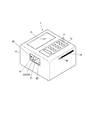
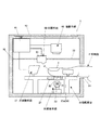
図1は、本実施形態におけるネイルプリント装置の外観を示す斜視図であり、図2は、ネイルプリント装置の内部構成を示した側断面図である。
図1及び図2に示すように、このネイルプリント装置1は、ほぼ立方体形状の筐体10を備えている。
この筐体10の上面には、各種操作ボタン11が配置された操作盤12と、液晶パネル等により構成される表示部13とを備えている。
筐体10の前面には、印刷しようとする爪部Tに対応する指F(以下「印刷指」という。)を装置内に挿入するための指挿入口14が形成されている。
また、筐体10の側面には、インターフェースとして、各種記憶媒体(メモリカード等)を挿入可能なカード挿入部15と、各種装置(携帯電話又はパソコン等)にUSBを介して接続可能なUSB接続部16とが設けられている。なお、インターフェースは、外部装置と接続可能なものであればよく、ここに示した例に限定されない。
FIG. 1 is a perspective view showing an appearance of a nail print apparatus according to the present embodiment, and FIG. 2 is a side sectional view showing an internal configuration of the nail print apparatus.
As shown in FIGS. 1 and 2, the nail print apparatus 1 includes a substantially
On the upper surface of the
A finger insertion opening 14 for inserting a finger F (hereinafter referred to as “printing finger”) corresponding to the nail portion T to be printed into the apparatus is formed on the front surface of the
Further, on the side surface of the
一方、筐体10の内部には、図2に示すように、指配置台20、照明手段30、撮像手段40、印刷手段50及び制御基板61を備えている。
On the other hand, as shown in FIG. 2, the
図3は、このうち指配置台20の斜視図を示している。
この指配置台20は、筐体10に形成された指挿入口14の内方に配置されている。この指配置台20は、筐体10の底面から隔たった指載置板21を備えている。
指載置板21は、指挿入口14から筐体10内に挿入される印刷指Fを下方から支持する。この指載置板21の上面には、印刷指Fの位置合わせを容易にするため、印刷指Fの腹に適合するような形状を有する指載置溝22が形成されている。
FIG. 3 shows a perspective view of the finger placement table 20 among them.
The finger placement table 20 is placed inside the
The
また、指載置板21の上面には、指固定機構24の一部を構成する1対の可動板23a,23bが配置されている。この1対の可動板23a、23bは、指載置溝22を間に挟んで対称となる位置に設けられ、指載置溝22に直交する方向に延在するレール部25に沿って互いに離接する方向に移動可能に設けられている。この1対の可動板23a,23bは、図示しない動力伝達手段を介してモータ26(図4参照)に連結されている。そして、モータ26の正逆回転により、レール部25に沿って互いに離接する方向に移動する。これによって、1対の可動板23a,23bは、指載置板21の上に載置された印刷指Fに対して当接する位置と、当該印刷指Fに対して離間する位置とを取り得る。1対の可動板23a,23bが印刷指Fに対して当接する位置では、印刷指Fが挟持されて固定される。
なお、可動板23a,23bは、1対に限定されず、複数対設けられていてもよい。
A pair of
The
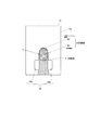
さらに、指載置板21の上面には、爪刺激機構27の一部を構成する爪刺激部材27aが配置されている。この爪刺激部材27aは、指載置溝22の奥側位置に設けられ、指載置溝22に平行な方向に延在する1対のレール部28、28に沿って移動可能に構成されている。この爪刺激部材27aは、図示しない動力伝達手段を介してモータ29(図4参照)に連結されている。そして、モータ29の正逆回転により、1対のレール部28,28に沿って移動する。これによって、爪刺激部材27aは、指載置板21の上面に載置された印刷指Fの爪先端Pに対して当接する位置と、当該爪先端Pに対して離間する位置とを取り得る。爪刺激部材27aが印刷指Fの爪先端Pに対して当接する位置では、爪先端
Pに対して圧力を加えることにより爪部Tを刺激し、この刺激により爪部Tの色を変化させる。
Further, a
この爪刺激部材27aの細部について説明すれば、爪刺激部材27aにおいて印刷指Fの爪先端Pに対向する部分は、図6(A)及び図7(A)に示すように、爪先端Pに当接する突き当て面27bを構成している。
この突き当て面27bは、鉛直方向と角度θをもって爪先端Pと接するように、指挿入口14側に向けて傾倒する傾斜面となっている。この突き当て面27bは、爪先端Pに対して突き当たった際に、上方からの押圧力を加えて爪先端Pを下方に押し下げるように機能する。これによって、爪床下部の毛細血管が圧せられて爪部Tの色を白っぽく変化させることができる。
The details of the
The
上記照明手段30は指下ライト33を備えている。この指下ライト33は、図2に示すように、指載置板21の下方に配置されている。正確には、指下ライト33は、載置板21に載置される印刷指Fの指爪の下方に配置されている。
この照明手段30は、撮像手段40による指爪の撮像の際に、指載置溝22内に固定された印刷指Fの指爪を当該印刷指Fの腹側から照明する。この照明は、主に、光透過率が比較的に低い爪先フリーエッジ領域N2(図8参照)の輪郭を明確化するために行われる。
この目的を達成するため、指載置板21の指載置溝22の底面において指爪領域に相当する部分には透光孔31が形成されている。そして、この透光孔31の上部には、アクリル板等の透明度の高い透明板32が付設されている。なお、この透明板32の上面は指載置溝22の底面の一部を形成している。
The
The
In order to achieve this object, a
上記撮像手段40は、例えばドライバーを内蔵した200万画素程度以上の画素を有するカメラ41と、このカメラ41を囲むように配置された白色LED等の照明灯42(図4参照)とを備えている。
この撮像手段40は、照明灯42によって、指配置台20の上に載置された印刷指Fを照明し、カメラ41によって印刷指Fの指爪を撮像して指爪画像を取得する。
The imaging means 40 includes a
The
上記印刷手段50は、例えばインクジェット方式の印刷ヘッド51(図4参照)を備えている。この印刷ヘッド51は、図示しない動力伝達手段を介してモータ53(図4参照)に連結され、モータ53の正逆回転によって、ガイドロッド52に沿って前後方向に移動するように構成されている。
なお、筐体10内には、印刷ヘッド51にインクを供給するための図示しないインクカートリッジが設けられ、印刷ヘッド51にインクを適宜に供給可能となっている。
The printing means 50 includes, for example, an inkjet print head 51 (see FIG. 4). The
An ink cartridge (not shown) for supplying ink to the
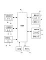
次に、図4を参照しつつ、本実施形態の制御構成について説明する。
本実施形態の制御構成の中核となる制御部60は、制御基板61上に実装されている。この制御部60は、図示しないCPU(Central Processing Unit)、ROM(Read Only
Memory)、RAM(Random Access Memory)等を備えるコンピュータである。ROMやRAM等にはネイルデザイン等のデータや印刷プログラム等の各種プログラムが格納され、制御部60は、このプログラムを実行することによって各部を制御する。
Next, the control configuration of the present embodiment will be described with reference to FIG.
A
Memory (RAM), RAM (Random Access Memory), and the like. ROM, RAM, and the like store data such as nail design and various programs such as a printing program, and the
例えば、制御部60は、印刷指Fを固定する際、指固定機構24のモータ26の動作を制御して、1対の可動板23a、23bを互いに接近する方向に移動させる。この移動によって、印刷指Fが固定された後、制御部60は、撮像手段40のカメラ41及び照明灯42の動作を制御して、撮影手段40が印刷指Fの指爪画像Iを取得する。そして、制御部60は、指爪画像IをRAM等に記憶させると共に、この指爪画像Iに基づき、爪先端位置を検出する。
次に、制御部60は、爪刺激機構27のモータ29の動作を制御して、印刷指Fの爪先端Pへ刺激を付与する。この状態で、制御部60は、撮像手段40のカメラ41及び照明灯42の動作を制御して、撮像手段40が印刷指Fの指爪画像IIを取得する。そして、制御部60は、指爪画像IIをRAMに記憶させると共に、指爪画像I及び指爪画像IIを使用して、爪床領域N1の検出を行う。つまり、制御部60は、この爪床領域N1の検出手段として機能する。この爪床領域N1の検出手法については後述する。
次に、制御部60は、爪刺激機構27のモータ29の動作を制御して、印刷指Fの爪先端Pへの刺激を解除する。その後、制御部60は、照明手段30の指下ライト33の動作を制御して、印刷指Fの指爪領域を当該印刷指Fの腹側から照射する。この状態で、制御部60は、撮像手段40のカメラ41及び照明灯42の動作を制御して、印刷指Fの指爪画像IIIを取得する。そして、制御部60は、指爪画像I及び指爪画像IIIを使用して、爪先フリーエッジ領域N2の検出を行う。この爪先フリーエッジ領域N2の検出手法については後述する。
このようにして爪先フリーエッジ領域N2の検出が終了したならば、制御部60は、検出された爪床領域N1及び爪先フリーエッジ領域N2が区分された爪領域Nを含む指爪画像を生成すると共に、表示部13の動作を制御して、当該指爪画像を表示させ、ユーザに確認の機会を与える。
また、制御部60は、ユーザによる指爪画像の確認が終了したならば、表示部13の動作を制御して、印刷可能な複数のデザインを表示させ、ここでもユーザにデザイン選択の機会を与える。
そして、ユーザによるデザインの選択が行われたならば、ユーザが選択したデザインを合わせ込んだ施術後画像を生成すると共に、表示部13の動作を制御して、当該施術後画像を表示させ、ユーザに確認の機会を与える。
そして、このユーザによる施術後画像の確認が行われたならば、制御部60は、印刷手段50の印刷ヘッド51及びモータ53の動作を制御して、デザインの印刷を行う。つまり、制御部60は印刷制御手段として機能する。
なお、制御部60は、撮像手段40で撮像された画像をリアルタイムで表示部13に表示させる。
For example, when fixing the printing finger F, the
Next, the
Next, the
When the detection of the toe free edge region N2 is completed in this way, the
In addition, when the confirmation of the fingernail image by the user is completed, the
If the user selects a design, a post-operative image is generated by combining the design selected by the user, and the operation of the
When the user confirms the post-treatment image, the
The
次に、制御部60による爪床領域N1の検出手法について説明する。
この爪床領域N1の検出は、指爪画像Iと指爪画像IIとを比較し、色変化が認められた領域を爪床領域N1と認定することによって行う。ここで「爪床領域」とは爪床に密着している爪領域をいう。
すなわち、印刷指Fの爪先端Pへ刺激を付与すると、爪床領域N1は白っぽく変色する。一方、爪床領域N1以外の部分についてはほとんど色変化が現れない。本実施形態では、このことを利用して、爪床領域N1の検出を行っている。
Next, a method for detecting the nail bed region N1 by the
The detection of the nail bed area N1 is performed by comparing the fingernail image I and the fingernail image II and identifying the area where the color change is recognized as the nail bed area N1. Here, the “nail bed area” refers to a nail area in close contact with the nail bed.
That is, when a stimulus is applied to the nail tip P of the printing finger F, the nail bed region N1 turns whitish. On the other hand, there is almost no color change in portions other than the nail bed region N1. In the present embodiment, this is utilized to detect the nail bed region N1.
図9は、図6(B)における一点鎖線部分(X−X)の横方向の輝度分布(輝度データY1)と、図7(B)における一点鎖線部分(X−X)の横方向の輝度分布(輝度データY2)とを1つのグラフ上に重ね合わせて示したものである。換言すれば、輝度データY1は指爪画像Iの輝度データ、輝度データY2は指爪画像IIの輝度データである。
この輝度データY1と輝度データY2とから制御部60は次のようにして爪床領域N1を検出する。
すなわち、制御部60は、指爪画像I及び指爪画像IIの対応する画素について、それぞれの輝度データY1、輝度データY2を比較し、第2の指爪画像IIの輝度データY2から第1の指爪画像Iの輝度データY1を差し引いた差分値(輝度差;Y2−Y1)を算出する。
そして、制御部60は、この差分値(輝度差;Y2−Y1)が、閾値a以上の場合(図9においてY2−Y1≧a)に爪床領域N1と判断する。
具体的には、輝度は、カメラで撮像されたカラー画像のR成分、B成分、G成分を元に、
0.3R+0.58B+0.11Gで求まる値とし、差分値(Y2−Y1)が、閾値a以上(図9においてY2−Y1≧a)であるか否かを判断し、そして、Y2−Y1≧aである場合には、制御部60は、爪床領域に密着した爪床領域N1と認定し、一方、Y2−Y1<aである場合には、爪床領域N1以外の領域(背景を含む)と認定する。
9 shows the luminance distribution (luminance data Y1) in the horizontal direction of the dashed-dotted line portion (XX) in FIG. 6B and the luminance in the horizontal direction of the dashed-dotted line portion (XX) in FIG. 7B. The distribution (luminance data Y2) is superimposed on one graph. In other words, the luminance data Y1 is the luminance data of the fingernail image I, and the luminance data Y2 is the luminance data of the fingernail image II.
From this luminance data Y1 and luminance data Y2, the
That is, the
And the
Specifically, the luminance is based on the R component, B component, and G component of the color image captured by the camera.
It is determined whether or not the difference value (Y2−Y1) is equal to or greater than a threshold value a (Y2−Y1 ≧ a in FIG. 9), and Y2−Y1 ≧ a. If it is, the
なお、この爪床領域N1の認定に使用される閾値aは、制御部60のROM等に予め記憶されていても、ユーザが任意に設定・調整できるものであってもよい。
爪床領域N1が実際の爪床領域よりも狭く検出されると、印刷したときに爪床領域全体に亘って印刷することができず、爪床領域の縁に空白が生じてしまう。このような場合には、閾値aを小さく設定する。例えば、ベースコートやオーバーコートを施す場合のように、爪床領域N1全体をコーティングするような印刷を行う場合、爪床領域N1が正確に検出できるように閾値aを小さく設定することが好ましい。
一方、爪床領域N1が実際の爪床領域よりも広く検出されると、印刷したときにデザインの一部が爪床領域N1からはみ出してしまい、印刷指Fの爪床領域以外を汚してしまう。このような場合には、閾値aを大きく設定する。例えば、所望のデザインが例えば花柄模様のようにワンポイント的なものである場合には、印刷が実際の爪床領域からはみ出さないように、閾値aを大きめに設定して、爪床領域N1を狭めに検出することが好ましい。
Note that the threshold value a used for recognition of the nail bed region N1 may be stored in advance in the ROM or the like of the
If the nail bed area N1 is detected to be narrower than the actual nail bed area, printing cannot be performed over the entire nail bed area, and a blank is generated at the edge of the nail bed area. In such a case, the threshold value a is set small. For example, when printing is performed so as to coat the entire nail bed region N1 as in the case of applying a base coat or overcoat, it is preferable to set the threshold value a small so that the nail bed region N1 can be accurately detected.
On the other hand, when the nail bed area N1 is detected wider than the actual nail bed area, a part of the design protrudes from the nail bed area N1 when printing is performed, and the areas other than the nail bed area of the printing finger F are stained. . In such a case, the threshold value a is set large. For example, if the desired design is a one-point design such as a floral pattern, for example, the threshold value a is set large so that printing does not protrude from the actual nail bed region, and the nail bed region It is preferable to detect N1 narrowly.
次に、制御部60による爪先フリーエッジ領域N2の検出手法について説明する。
図11は、指腹側から光の照射が行われる前の画像Iと光の照射が行われた状態での画像IIIとにおける爪床領域(爪先フリーエッジ領域を除く爪領域)N1、爪周辺皮膚及び爪先フリーエッジ領域N2のR成分の輝度値の変化の一例を示し、図11は、爪床領域N1、爪周辺皮膚及び爪先フリーエッジ領域N1のR成分の輝度値の差分値の一例を表したものである。
爪先フリーエッジ領域N2は、爪床領域N1や爪周辺の皮膚に比べて水分含有量が低く、また、爪下部の皮膚に密着しないで離れているため光の透過率が低い。その結果、爪先フリーエッジ領域N2は、他の領域に比べて、輝度値、特にR成分の変化が明らかに小さくなる。
そこで、制御部60は、指爪画像Iと指爪画像IIIについてそれぞれ対応する画素を比較し、指爪画像IのR成分をR1とし、指爪画像IIIのR成分をR3としたとき、R成分の変化が予め設定した閾値b以下であると認められた画素、即ち、R3−R1≦bを満たす画素を求め、それらの画素の集合を爪先フリーエッジ領域N2として認定する。
Next, a method for detecting the toe free edge region N2 by the
FIG. 11 shows the nail bed area (nail area excluding the toe free edge area) N1 and the periphery of the nail in the image I before light irradiation from the finger pad side and the image III in the light irradiation state FIG. 11 shows an example of a change in the luminance value of the R component of the skin and toe free edge region N2, and FIG. 11 shows an example of the difference value of the luminance value of the R component of the nail bed region N1, the skin around the nail and the toe free edge region N1. It is a representation.
The toe free edge region N2 has a lower water content than the nail bed region N1 and the skin around the nail, and has a low light transmittance because it is separated from the skin under the nail without being in close contact. As a result, in the toe free edge region N2, the change in luminance value, particularly the R component, is clearly smaller than in other regions.
Therefore, the
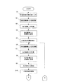
次に、図12及び図13のフローチャートを参照しつつ、本実施形態におけるネイルプリント装置1の作用を説明する。
まず、ユーザは、印刷指Fを選び、当該印刷指Fを指挿入口14から筐体10の内部に挿入して指載置板21の上面に載置する(図5及び図6参照)。この場合、印刷指Fが指載置溝22に載置され、且つ、透光孔31を印刷指Fの腹側で覆うようにする。
なお、このような状態を確実に取れるように、別途、印刷指Fの状態を検知するセンサを設けておいてもよい。
Next, the operation of the nail print apparatus 1 in the present embodiment will be described with reference to the flowcharts of FIGS.
First, the user selects the printing finger F, inserts the printing finger F into the inside of the
Note that a sensor for detecting the state of the printing finger F may be separately provided so as to ensure such a state.
次に、ユーザによる印刷処理の開始指示があると(ステップS1)、制御部60は、指固定機構24のモータ26の動作を制御し、可動板23a,23bを互いに接近する方向に移動させ、指載置溝22に載置された印刷指Fに突き当たる位置で可動板23a、23bを停止させる(図7参照)。これによって印刷指Fの左右方向の動きが規制され、印刷指Fの左右位置が固定される(ステップS2)。
その後、制御部60は、撮像手段40のカメラ41及び照明灯42の動作を制御し、撮像手段40が印刷指Fを撮像し、指爪画像Iを取得する(ステップS3)。この場合の指爪画像Iの取得は、爪刺激無し(指刺激OFF)で且つ指下ライト33が非点灯(指下ラ
イトOFF)の状態で行われる。
そして、制御部60は、指爪画像IをRAM等に記憶すると共に(ステップS4)、指爪画像Iに基づいて印刷指Fの爪先端Pの位置を検出する(ステップS5)。
Next, when there is an instruction to start the printing process by the user (step S1), the
Thereafter, the
Then, the
次に、制御部60は、爪刺激機構27のモータ29の動作を制御し、爪先端Pに突き当たる位置まで爪刺激部材27aを移動させて、爪先端Pを押圧して爪先端部に刺激を加える(ステップS6)。これによって、爪先端Pに下方向の圧力が加わり、爪床下部の毛細血管が圧せられて爪床領域N1が白く変化する。
この状態で、撮像手段40のカメラ41及び照明灯42の動作を制御し、印刷指Fを撮像し、指爪画像IIを取得する(ステップS7)。この場合の指爪画像IIの取得は、爪刺激有り(指刺激ON)で且つ指下ライト33が非点灯(指下ライトOFF)の状態で行われる。
そして、制御部60は、指爪画像IIを記憶部に記憶すると共に(ステップS8)、指爪画像IIに基づいて印刷指Fの爪床領域N1を検出する(ステップS9)。
Next, the
In this state, the operations of the
The
このようにして爪床領域N1の検出が完了すると、制御部60は、爪刺激機構27のモータ29の動作を制御し、爪先端Pから爪刺激部材27aを離間させて、爪先端Pへの刺激を解除する(ステップS10)。
次に、制御部60は、照明手段30の指下ライト33の動作を制御して、指下ライト33を点灯させ(ステップS11)、この状態で、さらに撮像手段40のカメラ41及び照明灯42の動作を制御し、撮像手段40が印刷指Fを撮像し、指爪画像IIIを取得する(ステップS12)。この場合の指爪画像IIIの取得は、爪刺激無し(指刺激OFF)で且つ指下ライト33が点灯(指下ライトON)の状態で行われる。
そして、制御部60は、取得した指爪画像IIIを記憶部に記憶すると共に(ステップS13)、指爪画像IIIに基づいて印刷指Fの爪先フリーエッジ領域N2を検出する(ステップS14)。この爪先フリーエッジ領域N2が検出されることで、爪床領域N1の境界も明瞭に検出されることになる。
When the detection of the nail bed region N1 is completed in this way, the
Next, the
And the
このようにして爪先フリーエッジ領域N2の検出が完了すると、制御部60は、照明手段30の指下ライト33の動作を制御して、指下ライト33を消灯させる(ステップS15)。
次に、制御部60は、表示部13の動作を制御して、表示部13の画面に爪領域の検出結果を表示させる(ステップS16)。この場合の表示は、例えば図8に示すように、爪領域Nと判断した領域(図8において網目で囲まれた爪床領域N1と爪先フリーエッジ領域N2)を指爪画像と重ね合わせた指爪画像13aを表示部13に表示させることによって行う
When the detection of the toe free edge region N2 is completed in this way, the
Next, the
ユーザは、この画面において、指爪画像の確認を行うことができる。そして、ユーザは、画面に表示された指爪画像が実際の指爪と対応しているか否か、つまり、画面に表示された指爪画像の適否を操作盤12から入力することができる。
制御部60は、ユーザによる適否の入力を受け付け、このユーザ入力に基づき、検出された指爪画像が適正でないと判断したならば(ステップS17でNO)、ステップS6からの工程を繰り返す。或いは、ユーザが操作盤12を操作することにより爪領域Nの修正・微調整を行うことができるようになっていてもよい。この場合の爪領域Nの修正・微調整の手法は特に限定されないが、例えば、爪領域Nの位置を縦横に僅かずつ平行移動させたり、爪領域Nを拡大・縮小させたりすることにより、好ましい位置・範囲に調整する。
一方、制御部60は、ユーザ入力に基づき、検出された指爪画像が適正であると判断したならば(ステップS17でYES)、表示部13の動作を制御して、表示部13の画面に印刷可能なデザインを複数表示させる。
The user can check the fingernail image on this screen. The user can input from the
If the
On the other hand, if the
ユーザは、この画面に表示された複数のネイルデザインの中から所望のデザインの選択を行う。このデザインの選択は、操作盤12からの入力によって行う。この場合のデザインのデータは、制御部60のROM等の記憶部に記憶されているものに限定されない。例えば、カード挿入部15に挿入されたカードに記憶されているデータを取り込んだり、外部装置において作成したりダウンロードしたデザインのデータ等を、USB接続部16を介して取り込んで用いることも可能である。
制御部60は、ユーザによるデザインの選択を受け付けると、このユーザ選択に基づき、印刷すべきデザインを抽出する(ステップS18)。
そして、制御部60は、検出された爪領域にユーザ所望のデザインを合わせ込んだ施術後画像のデータを生成し、表示部13の動作を制御して、当該施術後画像を表示部13の画面に表示させる(ステップS19)。この場合の表示は、図10に示すように、所望のデザインを実際の指爪画像と重ね合わせた施術後画像13bを表示部13に表示させることによって行う。また、この場合、検出された爪領域Nの大きさに合わせてデザインが拡大又は縮小された形で、施術後画像が表示される。
The user selects a desired design from a plurality of nail designs displayed on this screen. This design selection is performed by input from the
Upon receiving the design selection by the user, the
And the
ユーザは、この画面において、施術後画像の確認を行うことができる。そして、ユーザは、画面に表示された施術後画像が所望するものか否か、つまり、画面に表示された施術後画像の適否を操作盤12から入力することができる。
制御部60は、ユーザによる適否の入力を受け付け、このユーザ入力に基づき、検出された施術後イメージが適正でないと判断したならば(ステップS20でNO)、ステップS18からの工程を繰り返す。なお、デザインについて、操作盤12からの入力によって、拡大・縮小等ができるようになっていてもよい。
一方、制御部60は、ユーザ入力に基づき、検出された施術後画像が適正であると判断したならば(ステップS20でYES)、印刷部50の指固定機構24のモータ26の動作を制御して、可動板印刷ヘッド51及びモータ53の動作を制御して、爪領域の印刷を行う(ステップS21)。
The user can check the post-treatment image on this screen. Then, the user can input from the
When the
On the other hand, if the
このようにして、爪領域へのデザインの印刷が終了したならば、制御部60は、可動板23a,23bを互いに離間する方向に移動させ、印刷指Fの固定を解除させる(ステップS22)。これによって、印刷処理が終了する。
In this way, when the printing of the design on the nail region is completed, the
以上に説明したネイルプリント装置1によれば、次のような効果が得られる。
まず、印刷指Fの腹側から指爪を照明する前後の指爪画像I,IIIの色情報の変化に基づいて、爪領域を検出しているので、爪先フリーエッジ領域N2を検出しているので、爪領域Nを正確かつ安定的にしかも簡単に検出することができるばかりでなく、爪領域全域に対する印刷を確実かつ容易に行うことができる。
According to the nail printing apparatus 1 described above, the following effects can be obtained.
First, since the nail area is detected based on the change in color information of the fingernail images I and III before and after the fingernail is illuminated from the ventral side of the printing finger F, the nail free edge area N2 is detected. Therefore, not only the nail area N can be detected accurately and stably, but also the entire nail area can be printed reliably and easily.
また、印刷指Fの爪先端Pを爪刺激機構27によって刺激することにより爪領域Nの色を変化させるので、爪床領域N1と爪脇の皮膚との境界を確実に検出することができる。
Further, since the color of the nail region N is changed by stimulating the nail tip P of the printing finger F with the
なお、上記実施形態では、撮像手段40によって指爪画像I,II,IIIをこの順に取得しているが、その順序は問わないことは勿論である。 In the above embodiment, the fingernail images I, II, and III are acquired in this order by the imaging means 40, but the order is not limited.
以下に、この出願の願書に最初に添付した特許請求の範囲に記載した発明を付記する。付記に記載した請求項の項番は、この出願の願書に最初に添付した特許請求の範囲の通りである。
〔付記〕
<請求項1>
印刷指が載置される指配置台と、
前記印刷指の指爪を撮像して指爪画像を取得する撮像手段と、
前記撮像手段により撮像された指爪画像に基づいて爪領域を検出する爪領域検出手段と、
前記爪領域検出手段によって検出された爪領域に印刷を施すように制御する印刷制御手段と、
前記指配置台に載置された前記印刷指の指爪を当該印刷指の腹側から照明する照明手段と、を備え、
前記撮像手段は、前記指爪画像として、前記照明手段により照明しない状態で前記印刷指の指爪を撮像して得られる第1指爪画像と、前記照明手段により照明した状態で前記印刷指の指爪を撮像して得られる第2指爪画像とを取得し、
前記爪領域検出手段は、前記第1指爪画像と前記第2指爪画像との間の輝度変化を検出し、この輝度変化に基づいて、爪先フリーエッジ領域を検出する一方で、前記撮像手段により撮像された指爪画像に基づいて爪床領域を検出し、
前記印刷制御手段は、前記爪領域検出手段により検出された爪床領域と爪先フリーエッジ領域とからなる爪領域の全域に印刷を施すように制御することを特徴とするネイルプリント装置。
<請求項2>
前記爪領域検出手段は、前記第1画像及び前記第2画像であるカラー画像の中のR成分の輝度変化に基づいて、爪先フリーエッジ領域を検出することを特徴とする請求項1に記載のネイルプリント装置。
<請求項3>
前記印刷指の爪部に対して圧力を加えることにより当該爪部を刺激し、爪部の色を変化させる爪刺激機構をさらに備え、
前記撮像手段は、前記照明手段によって照射しない状態で且つ前記爪刺激機構によって前記印刷指の爪部を刺激した状態の第3指爪画像を取得し、
前記爪領域検出部は、さらに、前記第1指爪画像と前記第3指爪画像との色情報の変化に基づいて爪床領域を検出することを特徴とする請求項1または2に記載のネイルプリント装置。
<請求項4>
印刷指が載置される指配置台と、前記印刷指の指爪を撮像して指爪画像を取得する撮像手段とを備えているネイルプリント装置に用いられる印刷制御方法において、
前記指配置台に載置された前記印刷指の指爪を当該印刷指の腹側から照明しない状態で前記印刷指の指爪を撮像して第1指爪画像を取得し、前記照明した状態で前記印刷指の指爪を撮像して第2指爪画像を取得する画像取得ステップと、
前記第1指爪画像と前記第2指爪画像との間の輝度変化を検出し、この輝度変化に基づいて、爪先フリーエッジ領域を検出する一方で、前記撮像手段により撮像された指爪画像に基づいて爪床領域を検出する爪領域検出ステップと、
この爪領域検出ステップにより検出された爪床領域と爪先フリーエッジ領域とからなる爪領域の全域に印刷を施すように制御する印刷制御ステップと、
を備えていることを特徴とする印刷制御方法。
The invention described in the scope of claims attached to the application of this application will be added below. The item numbers of the claims described in the appendix are as set forth in the claims attached to the application of this application.
[Appendix]
<Claim 1>
A finger placement table on which printing fingers are placed;
Imaging means for capturing a fingernail image by capturing a fingernail of the printing finger;
Nail area detecting means for detecting a nail area based on a fingernail image imaged by the imaging means;
Print control means for controlling to perform printing on the nail area detected by the nail area detection means;
Illuminating means for illuminating the fingernail of the printing finger placed on the finger placement table from the ventral side of the printing finger,
The imaging unit includes a first fingernail image obtained by imaging a fingernail of the printing finger without being illuminated by the illumination unit as the fingernail image, and a state of the printing finger illuminated by the illumination unit. Obtaining a second fingernail image obtained by imaging the fingernail;
The nail area detecting means detects a luminance change between the first fingernail image and the second fingernail image, and detects a toe free edge area based on the luminance change, while the imaging means Detecting the nail bed area based on the fingernail image captured by
The nail printing apparatus characterized in that the printing control means controls to print over the entire nail area composed of a nail bed area and a toe free edge area detected by the nail area detecting means.
<Claim 2>
The said nail | claw area | region detection means detects a toe free edge area | region based on the luminance change of R component in the color image which is said 1st image and said 2nd image. Nail printing device.
<Claim 3>
Further comprising a nail stimulation mechanism that stimulates the nail part by applying pressure to the nail part of the printing finger and changes the color of the nail part;
The imaging unit obtains a third fingernail image in a state where the nail part of the printing finger is stimulated by the nail stimulation mechanism without being illuminated by the illumination unit,
The nail region detection unit further detects a nail bed region based on a change in color information between the first fingernail image and the third fingernail image. Nail printing device.
<Claim 4>
In a printing control method used in a nail printing apparatus including a finger placement table on which a printing finger is placed and an imaging unit that captures a fingernail of the printing finger and acquires a fingernail image,
The first fingernail image is acquired by imaging the fingernail of the printing finger without illuminating the fingernail of the printing finger placed on the finger placement base from the ventral side of the printing finger, and the illuminated state An image acquisition step of capturing a fingernail of the printing finger and acquiring a second fingernail image;
A brightness change between the first fingernail image and the second fingernail image is detected, and a toe free edge region is detected based on the brightness change, while the fingernail image captured by the imaging unit A nail area detecting step for detecting a nail bed area based on
A printing control step for controlling to perform printing on the entire area of the nail area composed of the nail bed area and the toe free edge area detected by the nail area detecting step;
A printing control method comprising:
1 ネイルプリント装置
20 指配置台
27 爪刺激機構
30 照明手段
33 指下ライト
40 撮像手段
50 印刷手段
60 制御部
F 印刷指
N 爪領域
N1 爪床領域
N2 爪先フリーエッジ領域
DESCRIPTION OF SYMBOLS 1
Claims (4)
前記印刷指の指爪を撮像して指爪画像を取得する撮像手段と、
前記撮像手段により撮像された前記指爪画像に基づいて爪領域を検出する爪領域検出手段と、
前記爪領域検出手段によって検出された前記爪領域に印刷を施すように制御する印刷制御手段と、
前記指配置台に載置された前記印刷指の指爪を当該印刷指の腹側から照明する照明手段と、を備え、
前記撮像手段は、前記指爪画像として、前記照明手段により照明しない状態で前記印刷指の指爪を撮像して得られる第1指爪画像と、前記照明手段により照明した状態で前記印刷指の指爪を撮像して得られる第2指爪画像とを取得し、
前記爪領域検出手段は、前記第1指爪画像と前記第2指爪画像との間の輝度変化を検出し、この輝度変化に基づいて、前記爪領域として、前記指爪の爪先領域と爪床領域とを検出することを特徴とするネイルプリント装置。 A finger placement table on which printing fingers are placed;
Imaging means for capturing a fingernail image by capturing a fingernail of the printing finger;
Nail area detecting means for detecting a nail area based on the fingernail image imaged by the imaging means;
Print control means for controlling to perform printing on the nail area detected by the nail area detection means;
Illuminating means for illuminating the fingernail of the printing finger placed on the finger placement table from the ventral side of the printing finger,
The imaging unit includes a first fingernail image obtained by imaging a fingernail of the printing finger without being illuminated by the illumination unit as the fingernail image, and a state of the printing finger illuminated by the illumination unit. Obtaining a second fingernail image obtained by imaging the fingernail;
The nail area detecting means detects a luminance change between the first fingernail image and the second fingernail image, and based on the luminance change, the nail area of the fingernail and the nail are used as the nail area. A nail printing apparatus for detecting a floor area.
前記撮像手段は、前記照明手段によって照射しない状態で且つ前記爪刺激機構によって前記印刷指の爪部を刺激した状態の第3指爪画像を取得し、
前記爪領域検出手段は、さらに、前記第1指爪画像と前記第3指爪画像との色情報の変化に基づいて前記爪床領域を検出することを特徴とする請求項1または2に記載のネイルプリント装置。 Further comprising a nail stimulation mechanism that stimulates the nail part by applying pressure to the nail part of the printing finger and changes the color of the nail part;
The imaging unit obtains a third fingernail image in a state where the nail part of the printing finger is stimulated by the nail stimulation mechanism without being illuminated by the illumination unit,
The nail area detection unit further detects the nail bed area based on a change in color information between the first fingernail image and the third fingernail image. Nail printing equipment.
前記指配置台に載置された前記印刷指の指爪を当該印刷指の腹側から照明しない状態で前記印刷指の指爪を撮像して第1指爪画像を取得し、前記照明した状態で前記印刷指の指爪を撮像して第2指爪画像を取得する画像取得ステップと、
前記第1指爪画像と前記第2指爪画像との間の輝度変化を検出し、この輝度変化に基づいて、前記指爪の爪先領域と爪床領域とを爪領域として検出する爪領域検出ステップと、
この爪領域検出ステップにより検出された前記爪領域に印刷を施すように制御する印刷制御ステップと、
を備えていることを特徴とする印刷制御方法。 In a printing control method used in a nail printing apparatus including a finger placement table on which a printing finger is placed and an imaging unit that captures a fingernail of the printing finger and acquires a fingernail image,
The first fingernail image is acquired by imaging the fingernail of the printing finger without illuminating the fingernail of the printing finger placed on the finger placement base from the ventral side of the printing finger, and the illuminated state An image acquisition step of capturing a fingernail of the printing finger and acquiring a second fingernail image;
A nail region detection that detects a luminance change between the first fingernail image and the second fingernail image and detects a toe region and a nail bed region of the fingernail as a nail region based on the luminance change. Steps,
A print control step for controlling to perform printing on the nail region detected by the nail region detection step;
A printing control method comprising:
Priority Applications (1)
| Application Number | Priority Date | Filing Date | Title |
|---|---|---|---|
| JP2011215097A JP5724802B2 (en) | 2011-09-29 | 2011-09-29 | Nail printing apparatus and printing control method |
Applications Claiming Priority (1)
| Application Number | Priority Date | Filing Date | Title |
|---|---|---|---|
| JP2011215097A JP5724802B2 (en) | 2011-09-29 | 2011-09-29 | Nail printing apparatus and printing control method |
Publications (3)
| Publication Number | Publication Date |
|---|---|
| JP2013074921A JP2013074921A (en) | 2013-04-25 |
| JP2013074921A5 JP2013074921A5 (en) | 2014-05-08 |
| JP5724802B2 true JP5724802B2 (en) | 2015-05-27 |
Family
ID=48478919
Family Applications (1)
| Application Number | Title | Priority Date | Filing Date |
|---|---|---|---|
| JP2011215097A Expired - Fee Related JP5724802B2 (en) | 2011-09-29 | 2011-09-29 | Nail printing apparatus and printing control method |
Country Status (1)
| Country | Link |
|---|---|
| JP (1) | JP5724802B2 (en) |
Families Citing this family (14)
| Publication number | Priority date | Publication date | Assignee | Title |
|---|---|---|---|---|
| JP6268771B2 (en) * | 2013-07-05 | 2018-01-31 | カシオ計算機株式会社 | Nail printing apparatus, printing method and program for nail printing apparatus |
| JP6128067B2 (en) * | 2014-06-27 | 2017-05-17 | カシオ計算機株式会社 | Drawing apparatus and drawing control method of drawing apparatus |
| JP6458426B2 (en) * | 2014-09-26 | 2019-01-30 | カシオ計算機株式会社 | Nail printing apparatus, nail printing apparatus operation control method, and nail printing apparatus operation control program |
| JP6476690B2 (en) * | 2014-09-26 | 2019-03-06 | カシオ計算機株式会社 | Nail printing apparatus, nail printing apparatus operation control method, and nail printing apparatus operation control program |
| JP6780320B2 (en) * | 2015-07-09 | 2020-11-04 | 船井電機株式会社 | Injection device |
| US10286683B2 (en) * | 2015-07-09 | 2019-05-14 | Funai Electric Co., Ltd. | Ejection device for applying droplets of fluid to object |
| JP6504047B2 (en) * | 2015-12-28 | 2019-04-24 | カシオ計算機株式会社 | Drawing device |
| JP6701853B2 (en) * | 2016-03-18 | 2020-05-27 | カシオ計算機株式会社 | Drawing device and drawing method of drawing device |
| JP6992367B2 (en) * | 2017-09-27 | 2022-01-13 | カシオ計算機株式会社 | Nail contour detection device, nail contour detection method and nail contour detection program |
| CN107898104A (en) * | 2017-12-29 | 2018-04-13 | 深圳市邻友通科技发展有限公司 | Finger fixed structure and nail beauty machine |
| JP6652184B2 (en) * | 2018-12-21 | 2020-02-19 | カシオ計算機株式会社 | Nail print apparatus, operation control method for nail print apparatus, and operation control program for nail print apparatus |
| JP7363409B2 (en) * | 2019-11-25 | 2023-10-18 | 船井電機株式会社 | printing device |
| KR102598081B1 (en) * | 2022-01-11 | 2023-11-03 | 김택수 | Toe fixing device |
| CN115022996A (en) * | 2022-06-29 | 2022-09-06 | 琥珀(深圳)多维科技有限公司 | Nail-beautifying lamp and nail-beautifying lamp control method |
Family Cites Families (3)
| Publication number | Priority date | Publication date | Assignee | Title |
|---|---|---|---|---|
| US6286517B1 (en) * | 1998-12-22 | 2001-09-11 | Pearl Technology Holdings, Llc | Fingernail and toenail decoration using ink jets |
| JP3016147B1 (en) * | 1998-12-25 | 2000-03-06 | 株式会社アトラス | Nail art equipment |
| JP2006255196A (en) * | 2005-03-17 | 2006-09-28 | Seiko Epson Corp | Nail drawing apparatus and nail drawing method |
-
2011
- 2011-09-29 JP JP2011215097A patent/JP5724802B2/en not_active Expired - Fee Related
Also Published As
| Publication number | Publication date |
|---|---|
| JP2013074921A (en) | 2013-04-25 |
Similar Documents
| Publication | Publication Date | Title |
|---|---|---|
| JP5724802B2 (en) | Nail printing apparatus and printing control method | |
| JP5593875B2 (en) | Nail printing device | |
| CN102948994B (en) | Nail print apparatus and printing control method | |
| CN105984213B (en) | The slant detection method of drawing apparatus and nail | |
| JP6561463B2 (en) | Drawing apparatus, drawing apparatus operation control method, and drawing apparatus operation control program | |
| JP7035405B2 (en) | Contour detection device, drawing device, contour detection method and contour detection program | |
| JP6439342B2 (en) | Nail information detection device, drawing device, and nail information detection method | |
| US20160088917A1 (en) | Nail design device, nail printing apparatus, nail design method, and computer-readable recording medium storing nail design program | |
| JP6476690B2 (en) | Nail printing apparatus, nail printing apparatus operation control method, and nail printing apparatus operation control program | |
| US10318838B2 (en) | Drawing apparatus, operation control method for drawing apparatus, and computer-readable recording medium | |
| JP2012232039A (en) | Nail printing device and printing control method thereof | |
| JP5879562B2 (en) | Mirror device with camera, fixture with mirror | |
| CN108618342B (en) | Drawing device, drawing method, and recording medium | |
| JP2019113972A (en) | Contour detection device, drawing device, contour detection method and contour detection program | |
| JP7047294B2 (en) | Contour detection device, drawing device, contour detection method and contour detection program | |
| JP6540021B2 (en) | Printing device, operation control method for printing device, and operation control program for printing device | |
| US20180343374A1 (en) | Imaging support device, and method for operating imaging support device | |
| JP2022169545A (en) | Drawing device, drawing method, and program | |
| JP2013192680A (en) | Nail printing device and print control method | |
| JP2013074923A (en) | Nail printing device, and printing control method | |
| JP2013039169A (en) | Nail printer and method for controlling print | |
| JP5104513B2 (en) | Photography editing method and apparatus | |
| JP6458426B2 (en) | Nail printing apparatus, nail printing apparatus operation control method, and nail printing apparatus operation control program | |
| JP5280996B2 (en) | Seal stamp direct reader and seal data creation method | |
| JP7334826B2 (en) | nail printing device |
Legal Events
| Date | Code | Title | Description |
|---|---|---|---|
| A521 | Written amendment |
Free format text: JAPANESE INTERMEDIATE CODE: A523 Effective date: 20140326 |
|
| A621 | Written request for application examination |
Free format text: JAPANESE INTERMEDIATE CODE: A621 Effective date: 20140326 |
|
| A131 | Notification of reasons for refusal |
Free format text: JAPANESE INTERMEDIATE CODE: A131 Effective date: 20141209 |
|
| A977 | Report on retrieval |
Free format text: JAPANESE INTERMEDIATE CODE: A971007 Effective date: 20141211 |
|
| A521 | Written amendment |
Free format text: JAPANESE INTERMEDIATE CODE: A523 Effective date: 20150209 |
|
| TRDD | Decision of grant or rejection written | ||
| A01 | Written decision to grant a patent or to grant a registration (utility model) |
Free format text: JAPANESE INTERMEDIATE CODE: A01 Effective date: 20150303 |
|
| A61 | First payment of annual fees (during grant procedure) |
Free format text: JAPANESE INTERMEDIATE CODE: A61 Effective date: 20150316 |
|
| R150 | Certificate of patent or registration of utility model |
Ref document number: 5724802 Country of ref document: JP Free format text: JAPANESE INTERMEDIATE CODE: R150 |
|
| LAPS | Cancellation because of no payment of annual fees |