EP3825023A1 - Tool for press brake - Google Patents
Tool for press brake Download PDFInfo
- Publication number
- EP3825023A1 EP3825023A1 EP19838694.8A EP19838694A EP3825023A1 EP 3825023 A1 EP3825023 A1 EP 3825023A1 EP 19838694 A EP19838694 A EP 19838694A EP 3825023 A1 EP3825023 A1 EP 3825023A1
- Authority
- EP
- European Patent Office
- Prior art keywords
- tool
- main body
- hole
- rotation
- bottomed
- Prior art date
- Legal status (The legal status is an assumption and is not a legal conclusion. Google has not performed a legal analysis and makes no representation as to the accuracy of the status listed.)
- Granted
Links
Images






Classifications
-
- B—PERFORMING OPERATIONS; TRANSPORTING
- B21—MECHANICAL METAL-WORKING WITHOUT ESSENTIALLY REMOVING MATERIAL; PUNCHING METAL
- B21D—WORKING OR PROCESSING OF SHEET METAL OR METAL TUBES, RODS OR PROFILES WITHOUT ESSENTIALLY REMOVING MATERIAL; PUNCHING METAL
- B21D5/00—Bending sheet metal along straight lines, e.g. to form simple curves
- B21D5/02—Bending sheet metal along straight lines, e.g. to form simple curves on press brakes without making use of clamping means
- B21D5/0209—Tools therefor
- B21D5/0254—Tool exchanging
-
- B—PERFORMING OPERATIONS; TRANSPORTING
- B21—MECHANICAL METAL-WORKING WITHOUT ESSENTIALLY REMOVING MATERIAL; PUNCHING METAL
- B21D—WORKING OR PROCESSING OF SHEET METAL OR METAL TUBES, RODS OR PROFILES WITHOUT ESSENTIALLY REMOVING MATERIAL; PUNCHING METAL
- B21D37/00—Tools as parts of machines covered by this subclass
- B21D37/04—Movable or exchangeable mountings for tools
-
- B—PERFORMING OPERATIONS; TRANSPORTING
- B21—MECHANICAL METAL-WORKING WITHOUT ESSENTIALLY REMOVING MATERIAL; PUNCHING METAL
- B21D—WORKING OR PROCESSING OF SHEET METAL OR METAL TUBES, RODS OR PROFILES WITHOUT ESSENTIALLY REMOVING MATERIAL; PUNCHING METAL
- B21D37/00—Tools as parts of machines covered by this subclass
- B21D37/14—Particular arrangements for handling and holding in place complete dies
- B21D37/145—Die storage magazines
-
- B—PERFORMING OPERATIONS; TRANSPORTING
- B21—MECHANICAL METAL-WORKING WITHOUT ESSENTIALLY REMOVING MATERIAL; PUNCHING METAL
- B21D—WORKING OR PROCESSING OF SHEET METAL OR METAL TUBES, RODS OR PROFILES WITHOUT ESSENTIALLY REMOVING MATERIAL; PUNCHING METAL
- B21D5/00—Bending sheet metal along straight lines, e.g. to form simple curves
- B21D5/02—Bending sheet metal along straight lines, e.g. to form simple curves on press brakes without making use of clamping means
-
- B—PERFORMING OPERATIONS; TRANSPORTING
- B21—MECHANICAL METAL-WORKING WITHOUT ESSENTIALLY REMOVING MATERIAL; PUNCHING METAL
- B21D—WORKING OR PROCESSING OF SHEET METAL OR METAL TUBES, RODS OR PROFILES WITHOUT ESSENTIALLY REMOVING MATERIAL; PUNCHING METAL
- B21D5/00—Bending sheet metal along straight lines, e.g. to form simple curves
- B21D5/02—Bending sheet metal along straight lines, e.g. to form simple curves on press brakes without making use of clamping means
- B21D5/0209—Tools therefor
-
- B—PERFORMING OPERATIONS; TRANSPORTING
- B21—MECHANICAL METAL-WORKING WITHOUT ESSENTIALLY REMOVING MATERIAL; PUNCHING METAL
- B21D—WORKING OR PROCESSING OF SHEET METAL OR METAL TUBES, RODS OR PROFILES WITHOUT ESSENTIALLY REMOVING MATERIAL; PUNCHING METAL
- B21D5/00—Bending sheet metal along straight lines, e.g. to form simple curves
- B21D5/02—Bending sheet metal along straight lines, e.g. to form simple curves on press brakes without making use of clamping means
- B21D5/0209—Tools therefor
- B21D5/0218—Length adjustment of the punch
-
- B—PERFORMING OPERATIONS; TRANSPORTING
- B21—MECHANICAL METAL-WORKING WITHOUT ESSENTIALLY REMOVING MATERIAL; PUNCHING METAL
- B21D—WORKING OR PROCESSING OF SHEET METAL OR METAL TUBES, RODS OR PROFILES WITHOUT ESSENTIALLY REMOVING MATERIAL; PUNCHING METAL
- B21D5/00—Bending sheet metal along straight lines, e.g. to form simple curves
- B21D5/02—Bending sheet metal along straight lines, e.g. to form simple curves on press brakes without making use of clamping means
- B21D5/0209—Tools therefor
- B21D5/0236—Tool clamping
-
- B—PERFORMING OPERATIONS; TRANSPORTING
- B23—MACHINE TOOLS; METAL-WORKING NOT OTHERWISE PROVIDED FOR
- B23Q—DETAILS, COMPONENTS, OR ACCESSORIES FOR MACHINE TOOLS, e.g. ARRANGEMENTS FOR COPYING OR CONTROLLING; MACHINE TOOLS IN GENERAL CHARACTERISED BY THE CONSTRUCTION OF PARTICULAR DETAILS OR COMPONENTS; COMBINATIONS OR ASSOCIATIONS OF METAL-WORKING MACHINES, NOT DIRECTED TO A PARTICULAR RESULT
- B23Q3/00—Devices holding, supporting, or positioning work or tools, of a kind normally removable from the machine
- B23Q3/155—Arrangements for automatic insertion or removal of tools, e.g. combined with manual handling
- B23Q3/1552—Arrangements for automatic insertion or removal of tools, e.g. combined with manual handling parts of devices for automatically inserting or removing tools
- B23Q3/1554—Transfer mechanisms, e.g. tool gripping arms; Drive mechanisms therefore
-
- Y—GENERAL TAGGING OF NEW TECHNOLOGICAL DEVELOPMENTS; GENERAL TAGGING OF CROSS-SECTIONAL TECHNOLOGIES SPANNING OVER SEVERAL SECTIONS OF THE IPC; TECHNICAL SUBJECTS COVERED BY FORMER USPC CROSS-REFERENCE ART COLLECTIONS [XRACs] AND DIGESTS
- Y10—TECHNICAL SUBJECTS COVERED BY FORMER USPC
- Y10T—TECHNICAL SUBJECTS COVERED BY FORMER US CLASSIFICATION
- Y10T483/00—Tool changing
- Y10T483/17—Tool changing including machine tool or component
- Y10T483/1729—Reciprocating tool machine tool [e.g., broaching machine, shaping machine, etc.]
- Y10T483/1731—Reciprocating tool machine tool [e.g., broaching machine, shaping machine, etc.] including matrix
-
- Y—GENERAL TAGGING OF NEW TECHNOLOGICAL DEVELOPMENTS; GENERAL TAGGING OF CROSS-SECTIONAL TECHNOLOGIES SPANNING OVER SEVERAL SECTIONS OF THE IPC; TECHNICAL SUBJECTS COVERED BY FORMER USPC CROSS-REFERENCE ART COLLECTIONS [XRACs] AND DIGESTS
- Y10—TECHNICAL SUBJECTS COVERED BY FORMER USPC
- Y10T—TECHNICAL SUBJECTS COVERED BY FORMER US CLASSIFICATION
- Y10T483/00—Tool changing
- Y10T483/18—Tool transfer to or from matrix
Definitions
- the present invention relates to a tool to be detachably attached to a tool installation portion of a press brake.
- Patent Literatures 1 to 3 disclose an upper tool as a tool to be automatically changed.
- the upper tool disclosed in Patent Literatures 1 to 3 comprises a tool main body.
- an attachment portion (a shank) to be detachably attached to the tool installation part of the press brake is formed.
- a tip side of the tool main body On a tip side of the tool main body, a bending portion to bend a plate-shaped workpiece is formed.
- a V-shaped groove engaged with a locking piece of the tool installation part is formed along a lateral direction.
- an accommodation depressed portion extending in a vertical direction is formed below the V-shaped groove in the surface of the attachment portion.
- an anti-drop operation member extending in the vertical direction is accommodated movably in a thickness direction (a direction along a thickness of a tool).
- a thickness direction a direction along a thickness of a tool.
- an engagement protrusion that is engageable in an engagement groove of the tool installation part is provided at an upper end of the operation member.
- a push button to release an engaged state of the engagement protrusion in the engagement groove of the tool installation part is provided.
- an elongated hole into which a hook member of the tool changer is inserted for operating the push button, extends through the tool below the push button in the thickness direction.
- the elongated hole is formed to be long in the vertical direction.
- Patent Literature 4 described below is also associated prior technical literature.
- Patent Literatures 1 and 2 as components for automatic change of the tool with respect to a tool installation portion of a press brake, an operation member extending in a vertical direction and elongated holes extending in the vertical direction and arranged in series in the vertical direction to the operation member are required. Furthermore, in a tool to be automatically changed, disclosed in Patent Literature 3, as such a component, an operation member extending in a vertical direction is required. That is, a height of the tool to be automatically changed, disclosed in Patent Literatures 1 to 3, is larger than a height of a usual tool. Therefore, the usual tool may be post-processed, and modified to obtain the tool to be automatically changed.
- the elongated hole extends through an attachment portion of the tool to be automatically changed, disclosed in Patent Literatures 1 and 2, in a thickness direction below a push button.
- a bush to which a manipulator of a tool changer is nonrotatably coupled, is mounted in the tool, and this bush is threaded (or the bush is formed to have a rectangular cross section). Therefore, the tool to be automatically changed, disclosed in Patent Literatures 1 to 3, is not easy to produce, and much time is required for the production of the tool to be automatically changed.
- An object of the present invention is to provide a tool for a press brake, which is easy to produce and is suitable for automatic change.
- a tool for a press brake including a tool main body, an attachment portion formed on a base end side of the tool main body and configured to be detachably attached to a tool installation portion of the press brake by using a tool changer, and a bending portion formed on a distal end side of the tool main body and used to bend a plate-shaped workpiece, wherein an engagement hole having a circular cross-sectional shape to be engaged with a bar-shaped finger of the tool changer extends through the tool main body in a thickness direction, and an anti-rotation bottomed depressed portion configured to receive a distal end of an anti-rotation member of the tool changer is formed in a vicinity of the engagement hole in the tool main body.
- a tool for a press brake including a tool main body, an attachment portion formed on a base end side of the tool main body and configured to be detachably attached to a tool installation portion of the press brake, and a bending portion formed on a distal end side of the tool main body and used to bend a plate-shaped workpiece, wherein a through hole having a circular cross-sectional shape is formed in a thickness direction in the tool main body, and a bottomed depressed portion is formed in a vicinity of the through hole in the tool main body.
- a tool changer includes a manipulator that performs automatic change of a tool.
- a circular cross-sectional shape is not limited to a precisely circular cross-sectional shape, and includes a substantially circular shape close to the circular cross-sectional shape.
- FF indicates a front direction
- FR indicates a rear direction
- L indicates a left direction
- R indicates a right direction
- U indicates an up direction
- D indicates a down direction.
- an upper tool (a tool) 10 is automatically changed for a plurality of upper tool holders 14 (only one is shown) as tool installation parts of a press brake by using a tool changer 12.
- the tool changer 12 is disposed on a rear side of (behind) an upper table 16 of the press brake.
- the plurality of upper tool holders 14 are provided via a space in a right-left direction at a lower end of the upper table 16. Note that a dashed-dotted line arrow in Figure 1 only indicates an installation position of the upper tool 10, and does not indicate an installation path of the upper tool 10.
- FIG 3(a) and Figure 3(b) show a standard type upper tool 10 (10A), and Figure 4(a) and Figure 4(b) show a goose-neck type upper tool 10 (10B).
- Figure 5(a) and Figure 5(b) show a goose-neck type upper tool 10 (10C) with an expanded portion. Note that in Figure 1 and Figure 7 to Figure 17 , the goose-neck type upper tool 10 (10B) is shown as a representative of the upper tool 10 according to the embodiment.
- the upper tool 10 includes a tool main body 18.
- a tool main body 18 On a base end side (an upper end side) of the tool main body 18, an attachment portion 20 to be detachably attached to the upper tool holder 14 by the tool changer 12 is formed.
- a tip side (a lower end side) of the tool main body 18 On a tip side (a lower end side) of the tool main body 18, a bending portion 22 to bend a plate-shaped workpiece (not shown) is formed.
- the attachment portion 20 includes a vertical contact surface 20c on a back side thereof.
- the contact surface 20c of the attachment portion 20 comes in contact with a front surface of a holder main body 24 of the upper tool holder 14.
- the attachment portion 20 is fixed to the holder main body 24 by a first clamp 26 of the upper tool holder 14.
- the contact surface 20c of the attachment portion 20 comes in contact with a rear surface of the holder main body 24 of the upper tool holder 14.
- an anti-drop groove 20g is formed along a lateral direction (a direction along a width of the upper tool 10).
- a portion of the tool main body 18 which is close to the attachment portion 20 is thicker than another portion of the tool main body 18.
- the tool main body 18 includes, in an upper part thereof, a pressure receiving face 18p that receives press force (pressurizing force) of the upper table 16.
- the pressure receiving face 18p of the tool main body 18 is at right angles to the contact surface 20c of the attachment portion 20.
- an engagement hole 18h having a circular cross-sectional shape to be engaged with a round-bar shaped finger 30 in the tool changer 12 extends in a thickness direction (a direction along a thickness of the upper tool 10).
- the engagement hole 18h is a through hole having a circular cross-sectional shape and formed in the thickness direction.
- the gravity-center position GP in the tool main body 18 is positioned on a center line of the tool main body 18 in the lateral direction.
- the engagement hole 18h is positioned at the correspondent position, in the lateral direction, to the gravity-center position GP
- a center of the engagement hole 18h is positioned on a vertical line passing the gravity-center position GP (i.e., a straight line at right angles to a straight line extending in the lateral direction).
- a peripheral edge portion of the engagement hole 18h on a front side is formed as an engaged portion to be engaged with an engagement piece 32 of the finger 30 (see Figure 1 ).
- a peripheral edge portion of the engagement hole 18h on a back side is formed as an engaged portion to be engaged with the engagement piece 32 of the finger 30.
- each of the respective engagement holes 18h of the upper tools 10B and 10C includes a large-diameter portion 18ha on the anterior surface AS side, and includes a small-diameter portion 18hb on the back surface BS side.
- a ring-shaped inner stepped portion 18hc is formed at an intermediate position of the engagement hole 18h (a boundary between the large-diameter portion 18ha and the small-diameter portion 18hb).
- the inner stepped portion 18hc is formed as an engaged portion to be engaged with the engagement piece 32 of the finger 30 (see Figure 2 ).
- a peripheral edge portion of the engagement hole 18h on the back side is formed as an engaged portion to be engaged with the engagement piece 32 of the finger 30.
- a plurality of conical holes 18f are formed as a plurality of anti-rotation bottomed depressed portions in a vicinity of the engagement hole 18h on each of opposite surfaces (the anterior surface AS and the back surface BS) of the tool main body 18.
- Each conical hole 18f may receive a distal end of each pin-shaped anti-rotation member 34 of the tool changer 12.
- the conical holes 18f are positioned above the engagement hole 18h of the tool main body 18.
- An opening area of each conical hole 18f is smaller than an opening area of the engagement hole 18h.
- the conical holes 18f are engageable with the distal ends of the pin-shaped anti-rotation members 34, respectively, and come in contact with line contact or surface contact with the distal ends of the anti-rotation members 34, respectively.
- the plurality of conical holes 18f are arranged in a linearly symmetrical manner to a predetermined virtual line VL.
- the predetermined virtual line VL is a virtual line passing a center of the engagement hole 18h in parallel with the vertical direction (of the upper tool 10). Note that if at least one of the plurality of conical holes 18f is engageable with the distal end of the anti-rotation member 34, the remaining conical holes 18f do not have to be engageable with the distal ends of the anti-rotation members 34.
- the upper tool holder 14 includes such a known configuration as disclosed in Patent Literature 4, and includes the holder main body 24 at the lower end of the upper table 16 as described above. Furthermore, on a front side of the holder main body 24, the first clamp 26 that is swingable in the front-rear direction to press the attachment portion 20 of the upper tool 10 onto the front surface of the holder main body 24 is provided. On a rear side of the holder main body 24, provided is the second clamp 28 that is swingable in the front-rear direction to press the attachment portion 20 of the upper tool 10 onto a rear surface of the holder main body 24.
- a pressing operation of the first clamp 26 and the second clamp 28 and an operation of releasing the pressing operation are performed by driving a clamp cylinder 36 provided above the holder main body 24.
- the first clamp 26 includes, in a lower part thereof, an engagement hook 26c that is engageable in the anti-drop groove 20g of the attachment portion 20.
- the second clamp 28 includes, in a lower part thereof, an engagement hook 28c that is engageable in the anti-drop groove 20g of the attachment portion 20.
- the tool changer 12 automatically changes (installs and removes) the upper tool 10 for a plurality of upper tool holders 14 as tool installation parts.
- the tool changer 12 automatically changes the upper tool 10 for an upper stocker (not shown) in a tool storage (not shown) disposed on a left or right side of the press brake.
- the tool changer 12 automatically changes the upper tool 10 between the plurality of upper tool holders 14 and the upper stocker.
- a beam member 38 extending in the right-left direction is provided via a plurality of connecting members 40 (only one is shown).
- the beam member 38 is provided with a rack member 42 extending in the right-left direction.
- a guide rail 44 extending in the right-left direction is attached to the rack member 42.
- the guide rail 44 is coupled to a box-shaped first slider 46 that is movable in the right-left direction, via a plurality of linear sliders 48.
- the first slider 46 includes a bracket 46b in a rear part thereof.
- a servo motor 50 is provided as an actuator that slides the first slider 46 (relative to the upper table 16) in the right-left direction.
- a pinion gear 52 is fixed to an output shaft of the servo motor 50, and the pinion gear 52 meshes with the rack member 42.
- the servo motor 50 is driven, so that the first slider 46 may slide in the right-left direction.
- a base plate 54 is attached to a right side of the first slider 46.
- the base plate 54 is coupled to a second slider 56 that is movable in the front-rear direction, via a guide member 58.
- a hydraulic cylinder 60 is provided as a moving actuator that moves the second slider 56 in the front-rear direction relative to the first slider 46 and the base plate 54.
- the hydraulic cylinder 60 includes a piston rod 60r that can make a stroke in the front-rear direction, and a rear end of the piston rod 60r is connected to a bracket 46b of the first slider 46.
- the hydraulic cylinder 60 is driven, so that the second slider 56 may slide in the front-rear direction.
- the second slider 56 is provided with a third slider 62 that is movable in the front-rear direction, via a guide member (not shown).
- a hydraulic cylinder 64 is provided as an actuator that slides the third slider 62 (relative to the second slider 56) in the front-rear direction.
- the hydraulic cylinder 64 includes a piston rod 64r that is movable in the front-rear direction, and a tip of the piston rod 64r is coupled to a suitable position of the third slider 62.
- the hydraulic cylinder 64 is driven, so that the third slider 62 may move relative to the second slider 56 in the front-rear direction.
- the third slider 62 is brought into a state shown in Figure 2 .
- the hydraulic cylinder 64 is driven to move the third slider 62 rearward from the state shown in Figure 2 .
- a support block 66 is attached to a front part of the third slider 62.
- the finger 30 that supports the upper tool 10 protrudes forward from a front surface of the support block 66.
- the finger 30 extends in the front-rear direction, and may be inserted into the engagement hole 18h of the upper tool 10.
- the finger 30 includes a large-diameter portion 30a on a base end side thereof, and includes a small-diameter portion 30b that is insertable into the engagement hole 18h, on a tip side thereof.
- a tip (a front end) of the finger 30 is formed in a conical shape (a tapered shape).
- a ring-shaped outer stepped portion 30c that is abuttable on the tool main body 18 is formed.
- a slit 30s is formed at a tip of the small-diameter portion 30b of the finger 30.
- the engagement piece 32 that is swingable in an up-down direction is attached via a pivot pin 68.
- the engagement piece 32 is a part of the finger 30, and is capable of being protruded and retracted relative to an outer peripheral surface of the finger 30 when swinging in the up-down direction.
- the engagement piece 32 protrudes from the outer peripheral surface of the finger 30, to engage with the peripheral edge portion of the engagement hole 18h or the inner stepped portion 18hc of the engagement hole 18h.
- a stopper 70 that regulates downward swinging of the engagement piece 32 is also provided in the slit 30s of the finger 30.
- an operation rod 72 extending in the front-rear direction and movable in the front-rear direction is provided.
- a cutout 72n is formed, and a tip of the engagement piece 32 is intruded in the cutout 72n.
- a push face 72na that pushes the engagement piece 32 forward to swing the piece downward is formed at a rear end of the cutout 72n.
- a pull face 72nb that pulls the engagement piece 32 rearward to swing the piece upward is formed at a front end of the cutout 72n.
- a hydraulic cylinder 74 is provided as an actuator that swings the engagement piece 32 in the up-down direction.
- the hydraulic cylinder 74 includes a piston rod 74r that is movable in the front-rear direction, and a tip of the piston rod 74r is coupled to a base end (a rear end) of the operation rod 72.
- the operation rod 72 is moved in the front-rear direction, and the engagement piece 32 is swung in the up-down direction to be capable of being protruded and retracted relative to the outer peripheral surface of the finger 30.
- the tool changer 12 clamps the upper tool 10 between the engagement piece 32 protruded from an outer peripheral surface of a tip portion of the finger 30 and the outer stepped portion 30c of the finger 30.
- a configuration where the engagement piece 32 is capable of being protruded and retracted relative to the outer peripheral surface of the finger 30 is not limited to the above described configuration, and any suitable configuration may be employed.
- a movable pin may be provided in a tip portion of the operation rod 72, and the pin may be engaged in a slot formed in the engagement piece 32, so that according to this structure, the engagement piece 32 is capable of being protruded and retracted relative to the outer peripheral surface of the finger 30.
- the operation rod 72 may be provided with a cam or wedge member, and the cam or wedge member may be brought into contact with the engagement piece 32, so that according to this structure, the engagement piece 32 is capable of being protruded and retracted relative to the outer peripheral surface of the finger 30.
- the finger 30 is not limited to the round bar shape, and may be formed in a polygonal-bar shape such as a square bar-shape.
- the large-diameter portion 30a of the finger 30 is provided with a slide block 76 that is slidable relative to the finger 30 in the front-rear direction.
- the sliding of the slide block 76 is guided by the finger 30 (the large-diameter portion 30a).
- a pair of slide rods 78 that are slidable in the front-rear direction relative to the support block 66 are supported.
- the slide block 76 is coupled integrally to tips (front ends) of the pair of slide rods 78, and a connecting member 80 is coupled to base ends (rear ends) of the pair of slide rods 78.
- the slide block 76 shown in Figure 7 and Figure 8 is different in shape from the slide block 76 shown in Figure 1 and Figure 2 , but has the same function (schematically shown in Figure 7 and Figure 8 ).
- the above described plurality of pin-shaped anti-rotation members 34 that prevent rotation of the upper tool 10 supported by the finger 30 are attached to a front surface of the slide block 76.
- the plurality of anti-rotation member 34 are arranged in a linearly symmetrical manner to a virtual vertical line passing an axial center of the finger 30 (a center line in the up-down direction).
- Each of the distal ends of the anti-rotation members 34 is formed in a conical (tapered) shape, and is engageable with the conical hole 18f.
- Each anti-rotation member 34 presses the upper tool 10 toward the engagement piece 32 protruded from the outer peripheral surface of the finger 30.
- each anti-rotation member 34 cooperates with the engagement piece 32 protruded from the outer peripheral surface of the finger 30 to clamp the upper tool 10.
- the distal end of each anti-rotation member 34 may be formed in a polygonal prism shape such as a columnar or quadrangular prism shape.
- the third slider 62 is provided with a hydraulic cylinder 82 as an actuator that moves the plurality of anti-rotation members 34 in the front-rear direction to the third slider 62.
- the hydraulic cylinder 82 includes a piston rod 82r that is movable in the front-rear direction, and a tip of the piston rod 82r is coupled to the connecting member 80.
- the hydraulic cylinder 82 is driven, so that the plurality of anti-rotation members 34 may be moved integrally with the slide block 76 in the front-rear direction to be engaged in and disengaged from the conical holes 18f.
- the first slider 46 Upon releasing the pressing of the attachment portion 20 with the first clamp 26 and the second clamp 28 (the upper tool 10 does not drop down), the first slider 46 is moved in the right-left direction, and the finger 30 is opposed to the engagement hole 18h.
- the second slider 56 moves forward to insert the finger 30 into the engagement hole 18h.
- the outer stepped portion 30c of the finger 30 abuts on the peripheral edge portion of the engagement hole 18h.
- the engagement piece 32 protrudes from the outer peripheral surface of the finger 30, to engage with the peripheral edge portion of the engagement hole 18h or the inner stepped portion 18hc of the engagement hole 18h. Consequently, the upper tool 10 is clamped between the engagement piece 32 and the outer stepped portion 30c of the finger 30.
- the anti-rotation members 34 are moved forward integrally with the slide block 76, and the distal ends of the anti-rotation members 34 engage in the conical holes 18f, respectively.
- the upper tool 10 is supported by the finger 30 in a non-rotatable state to the finger 30.
- the first slider 46 is moved to the right (or to the left), so that the upper tool 10 is removed from the upper tool holder 14 (the upper table 16) while keeping a vertical posture.
- the width of the upper tool 10 is smaller than a space between the adjacent upper tool holders 14, the following operation may be performed.
- the upper tool 10 is supported by the finger 30, and then the first slider 46 is moved in the right-left direction, to once stop the upper tool 10 between the adjacent upper tool holders 14. Then, the second slider 56 is moved rearward, so that the upper tool 10 is removed from the upper tool holder 14 (the upper table 16) while keeping the vertical posture.
- the upper tool 10 is automatically changed for the upper stocker of the tool storage, a similar operation is performed. Consequently, the upper tool 10 can be automatically changed between the plurality of upper tool holders 14 and the upper stocker.
- the engagement hole 18h having the circular cross-sectional shape to be engaged with the finger 30 extends through the tool main body 18 in the thickness direction.
- the plurality of anti-rotation bottomed depressed portions (the conical holes 18f) that receive the distal ends of the anti-rotation members 34, respectively, are formed in the vicinity of the engagement hole 18h on each of the opposite surfaces of the tool main body 18.
- the conical holes 18f are engageable with the distal ends of the anti-rotation members 34, respectively.
- the engagement piece 32 is engaged with the peripheral edge portion or the inner stepped portion 18hc of the engagement hole 18h, and the distal ends of the anti-rotation members 34 engage in the conical holes 18f, respectively.
- the posture of the upper tool 10 to the finger 30 can be stabilized, while inhibiting the rotation of the upper tool 10 to the finger 30.
- the plurality of conical holes 18f are arranged in a linearly symmetrical manner to the predetermined virtual line VL, tilting of the upper tool 10 due to resistance (inertia) during the movement of the upper tool 10 in the right-left direction can be inhibited, and the posture of the upper tool 10 to the finger 30 can be further stabilized.
- the upper tool 10 can be automatically changed for the plurality of upper tool holders 14 of the press brake by using the tool changer 12.
- the height of the upper tool 10 to be automatically changed is set to about the same as a height of a usual upper tool (not shown), and the usual upper tool is post-processed. Consequently, the tool can be used as the upper tool 10 to be automatically changed. Furthermore, difficulty in production of the upper tool 10 to be automatically changed is eliminated, while production time for the upper tool 10 to be automatically changed can be shortened. That is, the upper tool 10 of the embodiment is easy to be produced (can be produced by modifying the existing tool) and is suitable for the automatic change.
- a plurality of columnar holes 18b are formed as a plurality of anti-rotation bottomed depressed portions in a vicinity of an engagement hole 18h on each of opposite surfaces of a tool main body 18.
- the columnar holes 18b are positioned above the engagement hole 18h of the tool main body 18.
- a beveled portion 18bc is formed in a peripheral edge portion of each of the columnar holes 18b.
- An opening area of each columnar hole 18b is smaller than an opening area of the engagement hole 18h.
- the columnar holes 18b are engageable with distal ends of pin-shaped anti-rotation members 34, respectively, and come in line contact with the distal ends of the anti-rotation members 34, respectively.
- the plurality of columnar holes 18b are arranged in a linearly symmetrical manner to a predetermined virtual line VL. Note that if at least one of the plurality of columnar holes 18b is engageable with the distal end of the anti-rotation member 34, the remaining columnar holes 18b do not have to be engageable with the distal ends of the anti-rotation members 34.
- the columnar hole 18b since the beveled portion 18bc is formed in the peripheral edge portion of each columnar hole 18b, the columnar hole 18b does not have any sharp edges. Therefore, damages such as cracks of the tool main body 18 due to the contact of the tool main body 18 with the anti-rotation member 34 can be prevented.
- a through groove 18g having a V-shaped cross section or rectangular cross section and extending in a lateral direction is formed as an anti-rotation bottomed depressed portion in a vicinity of an engagement hole 18h on each of opposite surfaces of a tool main body 18.
- the through groove 18g is positioned above the engagement hole 18h.
- a beveled portion 18gc is formed in each edge portion of the through groove 18g having the rectangular cross section.
- the through groove 18g is engageable with a distal end of a flat-plate shaped anti-rotation member 34' provided on a front surface of a slide block 76, and comes in line contact or surface contact with a distal end of the anti-rotation member 34'.
- the through groove 18g may be engageable with distal ends of a plurality of pin-shaped anti-rotation members 34 (see Figure 7 and Figure 8 ) .
- the through groove 18g extends in the lateral direction, a contact area of an inner surface of the through groove 18g with the anti-rotation member 34' can be sufficiently acquired. Therefore, tilting of the upper tool 10 due to resistance (inertia) during movement of the upper tool 10 in a right-left direction can be inhibited, and the posture of the upper tool 10 to the finger 30 can be further stabilized.
- the through groove 18g since the beveled portion 18gc is formed in each edge portion of the through groove 18g having the rectangular cross section, the through groove 18g does not have any sharp edges. Therefore, damages such as cracks of the tool main body 18 due to the contact of the tool main body 18 with the anti-rotation member 34 can be prevented.
- an elongated hole 18j having a V-shaped cross section or a rectangular cross section and extending in a lateral direction is formed as an anti-rotation bottomed depressed portion in a vicinity of an engagement hole 18h on each of opposite surfaces of a tool main body 18.
- the elongated hole 18j is positioned above the engagement hole 18h.
- a beveled portion 18jc is formed in each edge portion of the elongated hole 18j having the rectangular cross section.
- the elongated hole 18j is engageable with a distal end of a flat-plate shaped anti-rotation member 34' (see Figure 14 and Figure 15 ), and comes in line contact or surface contact with a distal end of the anti-rotation member 34'.
- the elongated hole 18j may be engageable with distal ends of a plurality of pin-shaped anti-rotation members 34 (see Figure 7 and Figure 8 ).
- the present invention is not limited to the above embodiments, and can be embodied, for example, in various aspects as follows.
- the tip portion of the finger 30 may be formed in a cylindrical shape, and in the tip portion of the finger 30, a slit extending in the front-rear direction may be formed. In this case, if a tapered push rod is pushed into the finger 30, an outer diameter of the tip portion of the finger 30 is enlarged, and the tip portion is pressed onto the inner peripheral surface of the engagement hole 18h. As a result, the tool 10 is supported by the finger 30.
- a configuration applied to the upper tool 10 may be applied to a lower tool (not shown) to be detachably attached to a lower tool holder (a tool installation portion omitted from the drawings) of the press brake.
- the present invention also extends to the upper tool 10 used (for use) in a general-purpose press brake that is not equipped with the tool changer 12.
Landscapes
- Engineering & Computer Science (AREA)
- Mechanical Engineering (AREA)
- Bending Of Plates, Rods, And Pipes (AREA)
- Automatic Tool Replacement In Machine Tools (AREA)
- Mounting, Exchange, And Manufacturing Of Dies (AREA)
Abstract
Description
- The present invention relates to a tool to be detachably attached to a tool installation portion of a press brake.
- To automatically change a tool for a tool installation part of a press brake, an automatic tool changer (ATC) may be used (see Patent Literatures 1 to 3 below). Patent Literatures 1 to 3 disclose an upper tool as a tool to be automatically changed.
- The upper tool disclosed in Patent Literatures 1 to 3 comprises a tool main body. On a base end side of the tool main body, an attachment portion (a shank) to be detachably attached to the tool installation part of the press brake is formed. On a tip side of the tool main body, a bending portion to bend a plate-shaped workpiece is formed. In each of opposite surfaces (a front surface and a back surface) of the attachment portion, a V-shaped groove engaged with a locking piece of the tool installation part is formed along a lateral direction.
- Below the V-shaped groove in the surface of the attachment portion, an accommodation depressed portion extending in a vertical direction is formed. In the accommodation depressed portion, an anti-drop operation member extending in the vertical direction is accommodated movably in a thickness direction (a direction along a thickness of a tool). At an upper end of the operation member, an engagement protrusion that is engageable in an engagement groove of the tool installation part is provided. Then, at a lower end of the operation member, a push button to release an engaged state of the engagement protrusion in the engagement groove of the tool installation part is provided. Additionally, for the tool to be automatically changed as disclosed in Patent Literatures 1 and 2, an elongated hole, into which a hook member of the tool changer is inserted for operating the push button, extends through the tool below the push button in the thickness direction. The elongated hole is formed to be long in the vertical direction.
- Note that in addition to Patent Literatures 1 to 3, Patent Literature 4 described below is also associated prior technical literature.
-
- Patent Literature 1: Japanese Patent No.
4558852 - Patent Literature 2: Japanese Patent No.
4672868 - Patent Literature 3: Japanese Patent No.
5252837 - Patent Literature 4: Japanese Patent No.
5841800 - In a tool to be automatically changed, disclosed in Patent Literatures 1 and 2, as components for automatic change of the tool with respect to a tool installation portion of a press brake, an operation member extending in a vertical direction and elongated holes extending in the vertical direction and arranged in series in the vertical direction to the operation member are required. Furthermore, in a tool to be automatically changed, disclosed in Patent Literature 3, as such a component, an operation member extending in a vertical direction is required. That is, a height of the tool to be automatically changed, disclosed in Patent Literatures 1 to 3, is larger than a height of a usual tool. Therefore, the usual tool may be post-processed, and modified to obtain the tool to be automatically changed.
- Furthermore, the elongated hole extends through an attachment portion of the tool to be automatically changed, disclosed in Patent Literatures 1 and 2, in a thickness direction below a push button. In the tool to be automatically changed, disclosed in Patent Literature 3, a bush, to which a manipulator of a tool changer is nonrotatably coupled, is mounted in the tool, and this bush is threaded (or the bush is formed to have a rectangular cross section). Therefore, the tool to be automatically changed, disclosed in Patent Literatures 1 to 3, is not easy to produce, and much time is required for the production of the tool to be automatically changed.
- An object of the present invention is to provide a tool for a press brake, which is easy to produce and is suitable for automatic change.
- As a first feature of the present invention provides a tool for a press brake including a tool main body, an attachment portion formed on a base end side of the tool main body and configured to be detachably attached to a tool installation portion of the press brake by using a tool changer, and a bending portion formed on a distal end side of the tool main body and used to bend a plate-shaped workpiece, wherein an engagement hole having a circular cross-sectional shape to be engaged with a bar-shaped finger of the tool changer extends through the tool main body in a thickness direction, and an anti-rotation bottomed depressed portion configured to receive a distal end of an anti-rotation member of the tool changer is formed in a vicinity of the engagement hole in the tool main body.
- As a second feature of the present invention provides a tool for a press brake including a tool main body, an attachment portion formed on a base end side of the tool main body and configured to be detachably attached to a tool installation portion of the press brake, and a bending portion formed on a distal end side of the tool main body and used to bend a plate-shaped workpiece, wherein a through hole having a circular cross-sectional shape is formed in a thickness direction in the tool main body, and a bottomed depressed portion is formed in a vicinity of the through hole in the tool main body.
-
- [
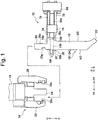
Figure 1] Figure 1 is a side view showing a standard type upper tool according to an embodiment, and an upper tool holder of a press brake. - [
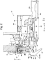
Figure 2] Figure 2 is a side view showing a goose-neck type upper tool according to the embodiment and the upper tool holder of the press brake. - [
Figure 3] Figure 3(a) is a front view of the above standard type upper tool, andFigure 3(b) is a side view of the upper tool. - [
Figure 4] Figure 4(a) is a front view of the above goose-neck type upper tool, andFigure 4(b) is a side view of the upper tool. - [
Figure 5] Figure 5(a) is a partial front view of the goose-neck type upper tool in which a plurality of anti-rotation bottomed depressed portions (conical holes) are formed in the tool main body, andFigure 5(b) is a cross-sectional view taken along the V-V line inFigure 5(a) . - [
Figure 6] Figure 6(a) is a front view of the goose-neck type upper tool (with an expanded portion) according to the embodiment, andFigure 6(b) is a side view of the upper tool. - [
Figure 7] Figure 7 is an exploded perspective view showing a relation between a peripheral configuration of a finger, including a pin-shaped anti-rotation member, and the upper tool. - [
Figure 8] Figure 8 is a side cross-sectional view showing a relation between the peripheral configuration of the finger, including the pin-shaped anti-rotation member, and the upper tool. - [
Figure 9] Figure 9(a) is a side cross-sectional view showing a behavior prior to engagement of an engagement piece in an inner stepped portion of an engagement hole, andFigure 9(b) is a perspective view showing a behavior that the engagement piece is pushed by a push face of the finger to abut on a stopper. - [
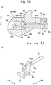
Figure 10] Figure 10(a) is a cross-sectional view showing a behavior that the engagement piece is engaged with the inner stepped portion of the engagement hole, andFigure 10(b) is a perspective view showing a behavior that the engagement piece is pulled up with a pull face of the finger. - [
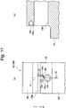
Figure 11] Figure 11(a) is a partial front view of a goose-neck type upper tool in which a plurality of anti-rotation bottomed depressed portions (columnar holes) are formed in a tool main body, andFigure 11(b) is a cross-sectional view taken along the XI-XI line inFigure 11(a) . - [
Figure 12] Figure 12(a) is a partial front view of a goose-neck type upper tool in which an anti-rotation bottomed depressed portion (a through groove having a V-shaped cross section) is formed in a tool main body, andFigure 12(b) is a cross-sectional view taken along the XII-XII line inFigure 12(a) . - [
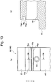
Figure 13] Figure 13(a) is a partial front view of the goose-neck type upper tool in which an anti-rotation bottomed depressed portion (a through groove having a rectangular cross section) is formed in the tool main body, andFigure 13(b) is a cross-sectional view taken along the XIII-XIII line inFigure 13(a) . - [
Figure 14] Figure 14 is an exploded perspective view showing a relation between a peripheral configuration of a finger including a flat-plate shaped anti-rotation member and the upper tool. - [
Figure 15] Figure 15 is a cross-sectional view showing a relation between the peripheral configuration of the finger including the flat-plate shaped anti-rotation member and the upper tool. - [
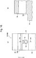
Figure 16] Figure 16(a) is a partial front view of a goose-neck type upper tool in which an anti-rotation bottomed depressed portion (an elongated hole having a V-shaped cross section) is formed in a tool main body, andFigure 16(b) is a cross-sectional view taken along the XVI-XVI line inFigure 16(a) . - [
Figure 17] Figure 17(a) is a partial front view of the goose-neck type upper tool in which an anti-rotation bottomed depressed portion (an elongated hole having a rectangular cross section) is formed in the tool main body, andFigure 17(b) is a cross-sectional view taken along the XVII-XVII line inFigure 17(a) . - Hereinafter, description will be made as to a tool for a press brake according to an embodiment with reference to the drawings.
- Note that "a tool changer" includes a manipulator that performs automatic change of a tool. "A circular cross-sectional shape" is not limited to a precisely circular cross-sectional shape, and includes a substantially circular shape close to the circular cross-sectional shape. In the drawings, "FF" indicates a front direction, "FR" indicates a rear direction, "L" indicates a left direction, "R" indicates a right direction, "U" indicates an up direction, and "D" indicates a down direction.
- As shown in
Figure 1 andFigure 2 , an upper tool (a tool) 10 according to an embodiment is automatically changed for a plurality of upper tool holders 14 (only one is shown) as tool installation parts of a press brake by using atool changer 12. Thetool changer 12 is disposed on a rear side of (behind) an upper table 16 of the press brake. The plurality ofupper tool holders 14 are provided via a space in a right-left direction at a lower end of the upper table 16. Note that a dashed-dotted line arrow inFigure 1 only indicates an installation position of theupper tool 10, and does not indicate an installation path of theupper tool 10. -
Figure 3(a) and Figure 3(b) show a standard type upper tool 10 (10A), andFigure 4(a) and Figure 4(b) show a goose-neck type upper tool 10 (10B).Figure 5(a) and Figure 5(b) show a goose-neck type upper tool 10 (10C) with an expanded portion. Note that inFigure 1 andFigure 7 toFigure 17 , the goose-neck type upper tool 10 (10B) is shown as a representative of theupper tool 10 according to the embodiment. - As shown in
Figure 3 ,Figure 4 andFigure 6 , theupper tool 10 includes a toolmain body 18. On a base end side (an upper end side) of the toolmain body 18, anattachment portion 20 to be detachably attached to theupper tool holder 14 by thetool changer 12 is formed. On a tip side (a lower end side) of the toolmain body 18, abending portion 22 to bend a plate-shaped workpiece (not shown) is formed. - As shown in
Figure 1 to Figure 4 andFigure 6 , theattachment portion 20 includes avertical contact surface 20c on a back side thereof. In a state where an anterior surface AS of theupper tool 10 faces forward, thecontact surface 20c of theattachment portion 20 comes in contact with a front surface of a holdermain body 24 of theupper tool holder 14. In a state where the anterior surface AS of theupper tool 10 faces forward, theattachment portion 20 is fixed to the holdermain body 24 by afirst clamp 26 of theupper tool holder 14. Furthermore, in a state where a back surface BS of theupper tool 10 faces forward due to a turn-over of an orientation of theupper tool 10, thecontact surface 20c of theattachment portion 20 comes in contact with a rear surface of the holdermain body 24 of theupper tool holder 14. In the state where the back surface BS of theupper tool 10 faces forward, theattachment portion 20 is fixed to the holdermain body 24 by asecond clamp 28 of theupper tool holder 14. Furthermore, on a front side of theattachment portion 20, ananti-drop groove 20g is formed along a lateral direction (a direction along a width of the upper tool 10). - A portion of the tool
main body 18 which is close to theattachment portion 20 is thicker than another portion of the toolmain body 18. The toolmain body 18 includes, in an upper part thereof, apressure receiving face 18p that receives press force (pressurizing force) of the upper table 16. Thepressure receiving face 18p of the toolmain body 18 is at right angles to thecontact surface 20c of theattachment portion 20. - As shown in
Figure 3 to Figure 6 , at a correspondent position, in the lateral direction, in the toolmain body 18 to a gravity-center position GP (of the upper tool 10), anengagement hole 18h having a circular cross-sectional shape to be engaged with a round-bar shapedfinger 30 in thetool changer 12 extends in a thickness direction (a direction along a thickness of the upper tool 10). Theengagement hole 18h is a through hole having a circular cross-sectional shape and formed in the thickness direction. Note that in a case where theupper tool 10 does not include an expandedportion 10e (seeFigure 5 ) protruded outwardly in the lateral direction, that is, in a case where a front view shape of theupper tool 10 is a rectangular shape, the gravity-center position GP in the toolmain body 18 is positioned on a center line of the toolmain body 18 in the lateral direction. When it is described that "theengagement hole 18h is positioned at the correspondent position, in the lateral direction, to the gravity-center position GP", it is indicated that in the front view, a center of theengagement hole 18h is positioned on a vertical line passing the gravity-center position GP (i.e., a straight line at right angles to a straight line extending in the lateral direction). - As shown in
Figure 1 andFigure 3 , in a case where thefinger 30 is inserted into theengagement hole 18h from a back surface BS side of theupper tool 10A with the anterior surface AS of theupper tool 10A facing forward, a peripheral edge portion of theengagement hole 18h on a front side is formed as an engaged portion to be engaged with anengagement piece 32 of the finger 30 (seeFigure 1 ). In a case where thefinger 30 is inserted into theengagement hole 18h from an anterior surface AS side of theupper tool 10A with the back surface BS of theupper tool 10A facing forward due to the turn-over of the orientation of theupper tool 10A, a peripheral edge portion of theengagement hole 18h on a back side is formed as an engaged portion to be engaged with theengagement piece 32 of thefinger 30. - As shown in
Figure 2 andFigure 4 toFigure 6 , each of therespective engagement holes 18h of theupper tools engagement hole 18h (a boundary between the large-diameter portion 18ha and the small-diameter portion 18hb), a ring-shaped inner stepped portion 18hc is formed. In a case where thefinger 30 is inserted into theengagement hole 18h from the back surface BS side of theupper tool upper tool engagement piece 32 of the finger 30 (seeFigure 2 ). In a case where thefinger 30 is inserted into theengagement hole 18h of the toolmain body 18 from the anterior surface AS side of theupper tool upper tool engagement hole 18h on the back side is formed as an engaged portion to be engaged with theengagement piece 32 of thefinger 30. - As shown in
Figure 3 to Figure 8 , a plurality ofconical holes 18f are formed as a plurality of anti-rotation bottomed depressed portions in a vicinity of theengagement hole 18h on each of opposite surfaces (the anterior surface AS and the back surface BS) of the toolmain body 18. Eachconical hole 18f may receive a distal end of each pin-shapedanti-rotation member 34 of thetool changer 12. Theconical holes 18f are positioned above theengagement hole 18h of the toolmain body 18. An opening area of eachconical hole 18f is smaller than an opening area of theengagement hole 18h. Theconical holes 18f are engageable with the distal ends of the pin-shapedanti-rotation members 34, respectively, and come in contact with line contact or surface contact with the distal ends of theanti-rotation members 34, respectively. The plurality ofconical holes 18f are arranged in a linearly symmetrical manner to a predetermined virtual line VL. The predetermined virtual line VL is a virtual line passing a center of theengagement hole 18h in parallel with the vertical direction (of the upper tool 10). Note that if at least one of the plurality ofconical holes 18f is engageable with the distal end of theanti-rotation member 34, the remainingconical holes 18f do not have to be engageable with the distal ends of theanti-rotation members 34. - Subsequently, a configuration of the
upper tool holder 14 will be described. - As shown in
Figure 1 andFigure 2 , theupper tool holder 14 includes such a known configuration as disclosed in Patent Literature 4, and includes the holdermain body 24 at the lower end of the upper table 16 as described above. Furthermore, on a front side of the holdermain body 24, thefirst clamp 26 that is swingable in the front-rear direction to press theattachment portion 20 of theupper tool 10 onto the front surface of the holdermain body 24 is provided. On a rear side of the holdermain body 24, provided is thesecond clamp 28 that is swingable in the front-rear direction to press theattachment portion 20 of theupper tool 10 onto a rear surface of the holdermain body 24. A pressing operation of thefirst clamp 26 and thesecond clamp 28 and an operation of releasing the pressing operation are performed by driving aclamp cylinder 36 provided above the holdermain body 24. Thefirst clamp 26 includes, in a lower part thereof, anengagement hook 26c that is engageable in theanti-drop groove 20g of theattachment portion 20. Thesecond clamp 28 includes, in a lower part thereof, anengagement hook 28c that is engageable in theanti-drop groove 20g of theattachment portion 20. - Subsequently, a configuration of the
tool changer 12 will be described. - As shown in
Figure 2 , thetool changer 12 automatically changes (installs and removes) theupper tool 10 for a plurality ofupper tool holders 14 as tool installation parts. Thetool changer 12 automatically changes theupper tool 10 for an upper stocker (not shown) in a tool storage (not shown) disposed on a left or right side of the press brake. In other words, thetool changer 12 automatically changes theupper tool 10 between the plurality ofupper tool holders 14 and the upper stocker. - Behind the upper table 16, a
beam member 38 extending in the right-left direction is provided via a plurality of connecting members 40 (only one is shown). Thebeam member 38 is provided with arack member 42 extending in the right-left direction. A guide rail 44 extending in the right-left direction is attached to therack member 42. The guide rail 44 is coupled to a box-shapedfirst slider 46 that is movable in the right-left direction, via a plurality of linear sliders 48. Thefirst slider 46 includes abracket 46b in a rear part thereof. At a suitable position of thefirst slider 46, aservo motor 50 is provided as an actuator that slides the first slider 46 (relative to the upper table 16) in the right-left direction. Apinion gear 52 is fixed to an output shaft of theservo motor 50, and thepinion gear 52 meshes with therack member 42. Thus, theservo motor 50 is driven, so that thefirst slider 46 may slide in the right-left direction. - A
base plate 54 is attached to a right side of thefirst slider 46. Thebase plate 54 is coupled to asecond slider 56 that is movable in the front-rear direction, via a guide member 58. At a suitable position of thesecond slider 56, ahydraulic cylinder 60 is provided as a moving actuator that moves thesecond slider 56 in the front-rear direction relative to thefirst slider 46 and thebase plate 54. Thehydraulic cylinder 60 includes apiston rod 60r that can make a stroke in the front-rear direction, and a rear end of thepiston rod 60r is connected to abracket 46b of thefirst slider 46. Thus, thehydraulic cylinder 60 is driven, so that thesecond slider 56 may slide in the front-rear direction. - The
second slider 56 is provided with athird slider 62 that is movable in the front-rear direction, via a guide member (not shown). At a suitable position of thesecond slider 56, a hydraulic cylinder 64 is provided as an actuator that slides the third slider 62 (relative to the second slider 56) in the front-rear direction. The hydraulic cylinder 64 includes apiston rod 64r that is movable in the front-rear direction, and a tip of thepiston rod 64r is coupled to a suitable position of thethird slider 62. Thus, the hydraulic cylinder 64 is driven, so that thethird slider 62 may move relative to thesecond slider 56 in the front-rear direction. - In a case where the
finger 30 is inserted into theengagement hole 18h from the back surface BS side of theupper tool 10 with the anterior surface AS of theupper tool 10 facing forward, thethird slider 62 is brought into a state shown inFigure 2 . On the other hand, in a case where thefinger 30 is inserted into theengagement hole 18h from the anterior surface AS side of theupper tool 10 with the back surface BS of theupper tool 10 facing forward, the hydraulic cylinder 64 is driven to move thethird slider 62 rearward from the state shown inFigure 2 . - As shown in
Figure 2 andFigure 7 toFigure 10 , asupport block 66 is attached to a front part of thethird slider 62. Thefinger 30 that supports theupper tool 10 protrudes forward from a front surface of thesupport block 66. Thefinger 30 extends in the front-rear direction, and may be inserted into theengagement hole 18h of theupper tool 10. Thefinger 30 includes a large-diameter portion 30a on a base end side thereof, and includes a small-diameter portion 30b that is insertable into theengagement hole 18h, on a tip side thereof. A tip (a front end) of thefinger 30 is formed in a conical shape (a tapered shape). At an intermediate position of the finger 30 (a boundary between the large-diameter portion 30a and the small-diameter portion 30b), a ring-shaped outer steppedportion 30c that is abuttable on the toolmain body 18 is formed. - A
slit 30s is formed at a tip of the small-diameter portion 30b of thefinger 30. In theslit 30s, theengagement piece 32 that is swingable in an up-down direction is attached via apivot pin 68. Theengagement piece 32 is a part of thefinger 30, and is capable of being protruded and retracted relative to an outer peripheral surface of thefinger 30 when swinging in the up-down direction. Theengagement piece 32 protrudes from the outer peripheral surface of thefinger 30, to engage with the peripheral edge portion of theengagement hole 18h or the inner stepped portion 18hc of theengagement hole 18h. Note that astopper 70 that regulates downward swinging of theengagement piece 32 is also provided in theslit 30s of thefinger 30. - In the
finger 30, anoperation rod 72 extending in the front-rear direction and movable in the front-rear direction is provided. At a tip (a front end) of theoperation rod 72, acutout 72n is formed, and a tip of theengagement piece 32 is intruded in thecutout 72n. A push face 72na that pushes theengagement piece 32 forward to swing the piece downward is formed at a rear end of thecutout 72n. On the other hand, a pull face 72nb that pulls theengagement piece 32 rearward to swing the piece upward is formed at a front end of thecutout 72n. - At a suitable position of the
third slider 62, ahydraulic cylinder 74 is provided as an actuator that swings theengagement piece 32 in the up-down direction. Thehydraulic cylinder 74 includes apiston rod 74r that is movable in the front-rear direction, and a tip of thepiston rod 74r is coupled to a base end (a rear end) of theoperation rod 72. By driving thehydraulic cylinder 74, theoperation rod 72 is moved in the front-rear direction, and theengagement piece 32 is swung in the up-down direction to be capable of being protruded and retracted relative to the outer peripheral surface of thefinger 30. Thetool changer 12 clamps theupper tool 10 between theengagement piece 32 protruded from an outer peripheral surface of a tip portion of thefinger 30 and the outer steppedportion 30c of thefinger 30. - A configuration where the
engagement piece 32 is capable of being protruded and retracted relative to the outer peripheral surface of thefinger 30 is not limited to the above described configuration, and any suitable configuration may be employed. For example, a movable pin may be provided in a tip portion of theoperation rod 72, and the pin may be engaged in a slot formed in theengagement piece 32, so that according to this structure, theengagement piece 32 is capable of being protruded and retracted relative to the outer peripheral surface of thefinger 30. Alternatively, theoperation rod 72 may be provided with a cam or wedge member, and the cam or wedge member may be brought into contact with theengagement piece 32, so that according to this structure, theengagement piece 32 is capable of being protruded and retracted relative to the outer peripheral surface of thefinger 30. Furthermore, thefinger 30 is not limited to the round bar shape, and may be formed in a polygonal-bar shape such as a square bar-shape. - As shown in
Figure 1 ,Figure 2 ,Figure 7 andFigure 8 , the large-diameter portion 30a of thefinger 30 is provided with aslide block 76 that is slidable relative to thefinger 30 in the front-rear direction. The sliding of theslide block 76 is guided by the finger 30 (the large-diameter portion 30a). In thesupport block 66 described above, a pair ofslide rods 78 that are slidable in the front-rear direction relative to thesupport block 66 are supported. Theslide block 76 is coupled integrally to tips (front ends) of the pair ofslide rods 78, and a connectingmember 80 is coupled to base ends (rear ends) of the pair ofslide rods 78. Note that theslide block 76 shown inFigure 7 andFigure 8 is different in shape from theslide block 76 shown inFigure 1 andFigure 2 , but has the same function (schematically shown inFigure 7 andFigure 8 ). - The above described plurality of pin-shaped
anti-rotation members 34 that prevent rotation of theupper tool 10 supported by thefinger 30 are attached to a front surface of theslide block 76. The plurality ofanti-rotation member 34 are arranged in a linearly symmetrical manner to a virtual vertical line passing an axial center of the finger 30 (a center line in the up-down direction). Each of the distal ends of theanti-rotation members 34 is formed in a conical (tapered) shape, and is engageable with theconical hole 18f. Eachanti-rotation member 34 presses theupper tool 10 toward theengagement piece 32 protruded from the outer peripheral surface of thefinger 30. That is, eachanti-rotation member 34 cooperates with theengagement piece 32 protruded from the outer peripheral surface of thefinger 30 to clamp theupper tool 10. Note that the distal end of eachanti-rotation member 34 may be formed in a polygonal prism shape such as a columnar or quadrangular prism shape. - The
third slider 62 is provided with ahydraulic cylinder 82 as an actuator that moves the plurality ofanti-rotation members 34 in the front-rear direction to thethird slider 62. Thehydraulic cylinder 82 includes apiston rod 82r that is movable in the front-rear direction, and a tip of thepiston rod 82r is coupled to the connectingmember 80. Thus, thehydraulic cylinder 82 is driven, so that the plurality ofanti-rotation members 34 may be moved integrally with theslide block 76 in the front-rear direction to be engaged in and disengaged from theconical holes 18f. - Subsequently, advantages of the embodiment will be described.
- Upon releasing the pressing of the
attachment portion 20 with thefirst clamp 26 and the second clamp 28 (theupper tool 10 does not drop down), thefirst slider 46 is moved in the right-left direction, and thefinger 30 is opposed to theengagement hole 18h. Next, thesecond slider 56 moves forward to insert thefinger 30 into theengagement hole 18h. The outer steppedportion 30c of thefinger 30 abuts on the peripheral edge portion of theengagement hole 18h. Theengagement piece 32 protrudes from the outer peripheral surface of thefinger 30, to engage with the peripheral edge portion of theengagement hole 18h or the inner stepped portion 18hc of theengagement hole 18h. Consequently, theupper tool 10 is clamped between theengagement piece 32 and the outer steppedportion 30c of thefinger 30. Next, theanti-rotation members 34 are moved forward integrally with theslide block 76, and the distal ends of theanti-rotation members 34 engage in theconical holes 18f, respectively. As a result, theupper tool 10 is supported by thefinger 30 in a non-rotatable state to thefinger 30. Then, thefirst slider 46 is moved to the right (or to the left), so that theupper tool 10 is removed from the upper tool holder 14 (the upper table 16) while keeping a vertical posture. - If the width of the
upper tool 10 is smaller than a space between the adjacentupper tool holders 14, the following operation may be performed. Theupper tool 10 is supported by thefinger 30, and then thefirst slider 46 is moved in the right-left direction, to once stop theupper tool 10 between the adjacentupper tool holders 14. Then, thesecond slider 56 is moved rearward, so that theupper tool 10 is removed from the upper tool holder 14 (the upper table 16) while keeping the vertical posture. - In a case where the
upper tool 10 is installed to theupper tool holder 14, an operation reverse to the above operation is performed. In this way, theupper tool 10 can be automatically changed (installed and removed) for theupper tool holder 14. - Also, in a case where the
upper tool 10 is automatically changed for the upper stocker of the tool storage, a similar operation is performed. Consequently, theupper tool 10 can be automatically changed between the plurality ofupper tool holders 14 and the upper stocker. - As described above, the
engagement hole 18h having the circular cross-sectional shape to be engaged with thefinger 30 extends through the toolmain body 18 in the thickness direction. The plurality of anti-rotation bottomed depressed portions (theconical holes 18f) that receive the distal ends of theanti-rotation members 34, respectively, are formed in the vicinity of theengagement hole 18h on each of the opposite surfaces of the toolmain body 18. Theconical holes 18f are engageable with the distal ends of theanti-rotation members 34, respectively. Consequently, if thefinger 30 is inserted into theengagement hole 18h, theengagement piece 32 is engaged with the peripheral edge portion or the inner stepped portion 18hc of theengagement hole 18h, and the distal ends of theanti-rotation members 34 engage in theconical holes 18f, respectively. As a result, the posture of theupper tool 10 to thefinger 30 can be stabilized, while inhibiting the rotation of theupper tool 10 to thefinger 30. - In particular, since the plurality of
conical holes 18f are arranged in a linearly symmetrical manner to the predetermined virtual line VL, tilting of theupper tool 10 due to resistance (inertia) during the movement of theupper tool 10 in the right-left direction can be inhibited, and the posture of theupper tool 10 to thefinger 30 can be further stabilized. - Thus, according to the embodiment, even if the
upper tool 10 is not provided with a member corresponding to an operation member extending in the vertical direction (the direction along the height of the upper tool 10) (see Patent Literatures 1 and 2) or an elongated hole, theupper tool 10 can be automatically changed for the plurality ofupper tool holders 14 of the press brake by using thetool changer 12. - Therefore, according to the embodiment, the height of the
upper tool 10 to be automatically changed is set to about the same as a height of a usual upper tool (not shown), and the usual upper tool is post-processed. Consequently, the tool can be used as theupper tool 10 to be automatically changed. Furthermore, difficulty in production of theupper tool 10 to be automatically changed is eliminated, while production time for theupper tool 10 to be automatically changed can be shortened. That is, theupper tool 10 of the embodiment is easy to be produced (can be produced by modifying the existing tool) and is suitable for the automatic change. - As shown in
Figure 11 , a plurality ofcolumnar holes 18b are formed as a plurality of anti-rotation bottomed depressed portions in a vicinity of anengagement hole 18h on each of opposite surfaces of a toolmain body 18. Thecolumnar holes 18b are positioned above theengagement hole 18h of the toolmain body 18. A beveled portion 18bc is formed in a peripheral edge portion of each of thecolumnar holes 18b. An opening area of eachcolumnar hole 18b is smaller than an opening area of theengagement hole 18h. Thecolumnar holes 18b are engageable with distal ends of pin-shapedanti-rotation members 34, respectively, and come in line contact with the distal ends of theanti-rotation members 34, respectively. The plurality ofcolumnar holes 18b are arranged in a linearly symmetrical manner to a predetermined virtual line VL. Note that if at least one of the plurality ofcolumnar holes 18b is engageable with the distal end of theanti-rotation member 34, the remainingcolumnar holes 18b do not have to be engageable with the distal ends of theanti-rotation members 34. - Also, according to the present modification 1, advantages similar to those of the above described embodiment are obtained.
- Furthermore, according to the present modification 1, since the beveled portion 18bc is formed in the peripheral edge portion of each
columnar hole 18b, thecolumnar hole 18b does not have any sharp edges. Therefore, damages such as cracks of the toolmain body 18 due to the contact of the toolmain body 18 with theanti-rotation member 34 can be prevented. - As shown in
Figure 12 to Figure 14 , a throughgroove 18g having a V-shaped cross section or rectangular cross section and extending in a lateral direction is formed as an anti-rotation bottomed depressed portion in a vicinity of anengagement hole 18h on each of opposite surfaces of a toolmain body 18. The throughgroove 18g is positioned above theengagement hole 18h. A beveled portion 18gc is formed in each edge portion of the throughgroove 18g having the rectangular cross section. The throughgroove 18g is engageable with a distal end of a flat-plate shaped anti-rotation member 34' provided on a front surface of aslide block 76, and comes in line contact or surface contact with a distal end of the anti-rotation member 34'. Note that the throughgroove 18g may be engageable with distal ends of a plurality of pin-shaped anti-rotation members 34 (seeFigure 7 andFigure 8 ) . - According to the present modification 2, if a
finger 30 is inserted into theengagement hole 18h, anengagement piece 32 is engaged with a peripheral edge portion or an inner stepped portion 18hc of theengagement hole 18h, and the distal end of the flat-plate shaped anti-rotation member 34' engages with the throughgroove 18g. As a result, a posture of anupper tool 10 to thefinger 30 can be stabilized, while inhibiting rotation of theupper tool 10 to thefinger 30. - In particular, since the through
groove 18g extends in the lateral direction, a contact area of an inner surface of the throughgroove 18g with the anti-rotation member 34' can be sufficiently acquired. Therefore, tilting of theupper tool 10 due to resistance (inertia) during movement of theupper tool 10 in a right-left direction can be inhibited, and the posture of theupper tool 10 to thefinger 30 can be further stabilized. - Also, according to the present modification 2, advantages similar to those of the above described embodiment are obtained.
- Furthermore, according to the present modification 2, since the beveled portion 18gc is formed in each edge portion of the through
groove 18g having the rectangular cross section, the throughgroove 18g does not have any sharp edges. Therefore, damages such as cracks of the toolmain body 18 due to the contact of the toolmain body 18 with theanti-rotation member 34 can be prevented. - As shown in
Figure 16 andFigure 17 , anelongated hole 18j having a V-shaped cross section or a rectangular cross section and extending in a lateral direction is formed as an anti-rotation bottomed depressed portion in a vicinity of anengagement hole 18h on each of opposite surfaces of a toolmain body 18. Theelongated hole 18j is positioned above theengagement hole 18h. A beveled portion 18jc is formed in each edge portion of theelongated hole 18j having the rectangular cross section. Theelongated hole 18j is engageable with a distal end of a flat-plate shaped anti-rotation member 34' (seeFigure 14 andFigure 15 ), and comes in line contact or surface contact with a distal end of the anti-rotation member 34'. Note that theelongated hole 18j may be engageable with distal ends of a plurality of pin-shaped anti-rotation members 34 (seeFigure 7 andFigure 8 ). - Also, according to the present modification 3, advantages similar to those of the above described modification 2 are obtained.
- The present invention is not limited to the above embodiments, and can be embodied, for example, in various aspects as follows. The tip portion of the
finger 30 may be formed in a cylindrical shape, and in the tip portion of thefinger 30, a slit extending in the front-rear direction may be formed. In this case, if a tapered push rod is pushed into thefinger 30, an outer diameter of the tip portion of thefinger 30 is enlarged, and the tip portion is pressed onto the inner peripheral surface of theengagement hole 18h. As a result, thetool 10 is supported by thefinger 30. Furthermore, a configuration applied to theupper tool 10 may be applied to a lower tool (not shown) to be detachably attached to a lower tool holder (a tool installation portion omitted from the drawings) of the press brake. The present invention also extends to theupper tool 10 used (for use) in a general-purpose press brake that is not equipped with thetool changer 12. - All contents of Japanese Patent Application Nos.
2018-134151 (filed on July 17, 2018 2018-134168 (filed on July 17, 2018 2018-140886 (filed on July 27, 2018 2018-169366 (filed on September 11, 2018 2019-87437 (filed on May 7, 2019 2019-92892 (filed on May 16, 2019 2019-109717 (filed on June 12, 2019 2019-111277 (filed on June 14, 2019 2019-126935 (filed on July 8, 2019
Claims (15)
- A tool for a press brake, comprising:a tool main body,an attachment portion formed on a base end side of the tool main body and configured to be detachably attached to a tool installation portion of the press brake by using a tool changer, anda bending portion formed on a distal end side of the tool main body and used to bend a plate-shaped workpiece, whereinan engagement hole having a circular cross-sectional shape to be engaged with a bar-shaped finger of the tool changer extends through the tool main body in a thickness direction, andan anti-rotation bottomed depressed portion configured to receive a distal end of an anti-rotation member of the tool changer is formed in a vicinity of the engagement hole in the tool main body.
- The tool according to claim 1, wherein
the anti-rotation bottomed depressed portion comprises a plurality of anti-rotation bottomed depressed portions,
the plurality of anti-rotation bottomed depressed portions are arranged in a linearly symmetrical manner to a virtual line passing a center of the engagement hole in parallel with a vertical direction, and
at least one of the plurality of anti-rotation bottomed depressed portions is engageable with the distal end of the anti-rotation member. - The tool according to claim 2, wherein each of the plurality of anti-rotation bottomed depressed portions is a conical hole or a columnar hole.
- The tool according to claim 1, wherein the anti-rotation bottomed depressed portion extends in a lateral direction and is engageable with the distal end of the anti-rotation member.
- The tool according to claim 4, wherein the anti-rotation bottomed depressed portion is a through groove having a V-shaped cross section or a rectangular cross section.
- The tool according to claim 4, wherein the anti-rotation bottomed depressed portion is an elongated hole having a V-shaped cross section or a rectangular cross section.
- A tool for a press brake, comprising:a tool main body,an attachment portion formed on a base end side of the tool main body and configured to be detachably attached to a tool installation portion of the press brake, anda bending portion formed on a distal end side of the tool main body and used to bend a plate-shaped workpiece, whereina through hole having a circular cross-sectional shape is formed in a thickness direction in the tool main body, anda bottomed depressed portion is formed in a vicinity of the through hole in the tool main body.
- The tool according to claim 7, wherein an opening area of the bottomed depressed portion is smaller than an opening area of the through hole.
- The tool according to claim 7 or 8, wherein
the bottomed depressed portion comprises a plurality of bottomed depressed portions, and
the plurality of bottomed depressed portions are arranged in a linearly symmetrical manner to a virtual line passing a center of the through hole in parallel with a vertical direction. - The tool according to claim 9, wherein each of the plurality of bottomed depressed portions is a conical hole or a columnar hole.
- The tool according to claim 9, wherein the bottomed depressed portion is a columnar hole, and
a beveled portion is formed in a peripheral edge portion of the columnar hole. - The tool according to claim 7, wherein the bottomed depressed portion is a through groove having a V-shaped cross section or a rectangular cross section and extending in a lateral direction.
- The tool according to claim 7, wherein
the bottomed depressed portion is a through groove having a rectangular cross section and extending in a lateral direction, and
a beveled portion is formed in each edge portion of the through groove. - The tool according to claim 7, wherein the bottomed depressed portion is an elongated hole having a V-shaped cross section or a rectangular cross section and extending in a lateral direction.
- The tool according to claim 7, wherein
the bottomed depressed portion is an elongated hole having a rectangular cross section and extending in a lateral direction, and
a beveled portion is formed in a peripheral edge portion of the elongated hole.
Applications Claiming Priority (10)
| Application Number | Priority Date | Filing Date | Title |
|---|---|---|---|
| JP2018134168 | 2018-07-17 | ||
| JP2018134151A JP6618576B1 (en) | 2018-07-17 | 2018-07-17 | Method of mounting split upper die on upper die holder provided on upper table in press brake, die changing device, and die stocker |
| JP2018140886 | 2018-07-27 | ||
| JP2018169366A JP6670900B2 (en) | 2018-09-11 | 2018-09-11 | Upper stocker |
| JP2019087437 | 2019-05-07 | ||
| JP2019092892 | 2019-05-16 | ||
| JP2019109717A JP6641515B1 (en) | 2018-07-27 | 2019-06-12 | Mold changing device |
| JP2019111277A JP6620259B1 (en) | 2018-07-17 | 2019-06-14 | Mold |
| JP2019126935A JP6618648B1 (en) | 2018-07-17 | 2019-07-08 | Mold |
| PCT/JP2019/028033 WO2020017539A1 (en) | 2018-07-17 | 2019-07-17 | Tool for press brake |
Publications (3)
| Publication Number | Publication Date |
|---|---|
| EP3825023A1 true EP3825023A1 (en) | 2021-05-26 |
| EP3825023A4 EP3825023A4 (en) | 2021-09-08 |
| EP3825023B1 EP3825023B1 (en) | 2026-04-15 |
Family
ID=74844173
Family Applications (5)
| Application Number | Title | Priority Date | Filing Date |
|---|---|---|---|
| EP19838058.6A Active EP3825027B1 (en) | 2018-07-17 | 2019-07-17 | Tool changer |
| EP19838694.8A Active EP3825023B1 (en) | 2018-07-17 | 2019-07-17 | Tool for press brake |
| EP19838059.4A Active EP3825028B1 (en) | 2018-07-17 | 2019-07-17 | Upper tool stocker |
| EP19837688.1A Withdrawn EP3825022A4 (en) | 2018-07-17 | 2019-07-17 | TOOL FOR A PRESS |
| EP19837570.1A Active EP3825026B1 (en) | 2018-07-17 | 2019-07-17 | Method for fitting divided upper tool to upper tool holder provided on upper table of a press brake |
Family Applications Before (1)
| Application Number | Title | Priority Date | Filing Date |
|---|---|---|---|
| EP19838058.6A Active EP3825027B1 (en) | 2018-07-17 | 2019-07-17 | Tool changer |
Family Applications After (3)
| Application Number | Title | Priority Date | Filing Date |
|---|---|---|---|
| EP19838059.4A Active EP3825028B1 (en) | 2018-07-17 | 2019-07-17 | Upper tool stocker |
| EP19837688.1A Withdrawn EP3825022A4 (en) | 2018-07-17 | 2019-07-17 | TOOL FOR A PRESS |
| EP19837570.1A Active EP3825026B1 (en) | 2018-07-17 | 2019-07-17 | Method for fitting divided upper tool to upper tool holder provided on upper table of a press brake |
Country Status (3)
| Country | Link |
|---|---|
| US (5) | US20210291252A1 (en) |
| EP (5) | EP3825027B1 (en) |
| CN (5) | CN112423908B (en) |
Families Citing this family (5)
| Publication number | Priority date | Publication date | Assignee | Title |
|---|---|---|---|---|
| US20210291252A1 (en) * | 2018-07-17 | 2021-09-23 | Amada Co., Ltd. | Tool for press brake |
| CN113751592B (en) * | 2021-09-18 | 2024-07-02 | 南京邮电大学 | Polygonal bending center die with self-locking and automatic dismounting functions |
| CN113857359B (en) * | 2021-09-18 | 2023-07-25 | 南京邮电大学 | An Automatic Die Changing System for CNC Bending Center |
| PL73784Y1 (en) * | 2022-04-08 | 2025-02-17 | Pmt Szerszamgep Kereskedelmi Es Szerviz Zarkoeruen Mukoedo Reszvenytarsasag | Press brake tool that attaches to a tool changer mounted on the robot |
| CN114888136B (en) * | 2022-07-14 | 2022-09-23 | 瑞铁机床(苏州)股份有限公司 | Automatic change quick retooling center of bending |
Family Cites Families (57)
| Publication number | Priority date | Publication date | Assignee | Title |
|---|---|---|---|---|
| US3779155A (en) * | 1970-12-31 | 1973-12-18 | Komatsu Mfg Co Ltd | Plural-slide transfer pressing apparatus |
| JPS6041292Y2 (en) | 1981-11-19 | 1985-12-16 | 丸機械工業株式会社 | folding machine |
| US4604787A (en) * | 1984-08-15 | 1986-08-12 | Transamerica Delaval Inc. | Tool changer for manipulator arm |
| JPH02251322A (en) * | 1989-03-22 | 1990-10-09 | Komatsu Ltd | Exchanging device of die for press |
| US5168745A (en) * | 1989-04-10 | 1992-12-08 | Yamazaki Mazak Kabushiki Kaisha | Die exchange apparatus for the use of a press brake |
| JPH04158926A (en) * | 1990-10-24 | 1992-06-02 | Amada Metrecs Co Ltd | Die-set system die for bending and device for automatically changing die using its die |
| JPH06234018A (en) | 1993-02-09 | 1994-08-23 | Komatsu Ltd | Automatic die changing device of press brake |
| JP3268914B2 (en) * | 1993-10-22 | 2002-03-25 | 株式会社アマダ | Mold changing method and apparatus in press brake |
| TW365857U (en) * | 1994-05-17 | 1999-08-01 | Amada Metrecs Co | Upper tool and upper tool holder apparatus for press brake |
| JPH09220618A (en) | 1996-02-13 | 1997-08-26 | Toupure Kk | Upper mold device for V-shaped bending machine |
| DE19643163A1 (en) * | 1996-10-18 | 1998-04-23 | Amada Gmbh | Tool changing device for a forming press and forming press tool changing device arrangement |
| JPH10211521A (en) | 1997-01-24 | 1998-08-11 | Murata Mach Ltd | Device for adjusting width of die of metal plate bending machine |
| JPH10263708A (en) | 1997-03-24 | 1998-10-06 | Murata Mach Ltd | Die width adjusting device in bending machine |
| JP3841923B2 (en) | 1997-06-20 | 2006-11-08 | 株式会社アマダ | Mold changing method, mold storage device and bending system in bending machine |
| JP3228902B2 (en) * | 1998-03-04 | 2001-11-12 | 株式会社アマダ | Upper die holder device |
| JP4558852B2 (en) | 1998-08-28 | 2010-10-06 | 株式会社アマダ | Mold and mold changer |
| ATE460998T1 (en) | 1999-01-13 | 2010-04-15 | Amada Co Ltd | PRESS BENDING SYSTEM |
| DE10060405B4 (en) | 2000-12-05 | 2007-03-15 | Bayerische Motoren Werke Ag | Inner gripper for pipes and bores |
| US6467327B1 (en) * | 2001-08-15 | 2002-10-22 | Wilson Tool International, Inc. | Press brake tool and tool holder |
| JP4242204B2 (en) | 2003-05-19 | 2009-03-25 | 株式会社アマダ | Bending machine |
| JP4582621B2 (en) | 2003-06-23 | 2010-11-17 | 株式会社アマダ | Bending machine |
| JP4883668B2 (en) * | 2005-06-15 | 2012-02-22 | 株式会社アマダ | Bending apparatus, mold arrangement method and mold stocker selection method |
| EP1925374B1 (en) | 2005-06-15 | 2014-05-21 | Amada Co., Ltd. | Bending device and method for managing die, method for arranging die and method for selecting die stocker |
| JP5041572B2 (en) * | 2005-06-15 | 2012-10-03 | 株式会社アマダ | Bending machine |
| US7168286B1 (en) | 2005-10-29 | 2007-01-30 | Pelech Bruno J | Device and method for securing a punch tool to a ram portion of a press brake |
| PL1862255T3 (en) | 2006-06-01 | 2011-08-31 | Wila Bv | Combination of an exchangeable tool and a manipulator |
| US7634935B2 (en) * | 2006-10-05 | 2009-12-22 | Rolleri S.P.A. | Quick upper tool coupling and uncoupling device of a press brake |
| WO2008050458A1 (en) | 2006-10-27 | 2008-05-02 | Komatsu Industries Corporation | Punch, handle usable therefor, and punch with handle |
| US8141408B2 (en) * | 2007-12-04 | 2012-03-27 | Mccauley Kirk Allen | Holder for press dies |
| AT508923B1 (en) * | 2009-11-10 | 2011-05-15 | Trumpf Maschinen Austria Gmbh | MANUFACTURING SYSTEM, ESPECIALLY FOR FREEFORM BENDING |
| JP5588819B2 (en) * | 2010-10-19 | 2014-09-10 | 株式会社アマダ | Upper mold holder device |
| AT511078B1 (en) * | 2011-05-10 | 2012-09-15 | Trumpf Maschinen Austria Gmbh | MANUFACTURING SYSTEM WITH A TOOL CHANGE SYSTEM |
| JP5759274B2 (en) * | 2011-06-06 | 2015-08-05 | 株式会社アマダホールディングス | Press brake and bending method |
| JP5841800B2 (en) | 2011-10-20 | 2016-01-13 | 株式会社アマダホールディングス | Upper mold holder |
| JP6211755B2 (en) * | 2011-11-04 | 2017-10-11 | 株式会社アマダホールディングス | Plate material processing apparatus, pressing mold and mold installation body |
| JP2013111610A (en) | 2011-11-29 | 2013-06-10 | Amada Co Ltd | Device for bending plate material |
| JP2014004604A (en) | 2012-06-25 | 2014-01-16 | Amada Co Ltd | Mold mounting stocker, mold storage device, mold and hand storage device, mold exchange method by robot and control device for the same |
| JP5970339B2 (en) * | 2012-11-01 | 2016-08-17 | 株式会社アマダホールディングス | Mold changer |
| AT514078B1 (en) * | 2013-06-20 | 2014-10-15 | Trumpf Maschinen Austria Gmbh | bending tool |
| JP2015120185A (en) | 2013-12-24 | 2015-07-02 | 株式会社アマダホールディングス | Press brake intermediate plate mounting device |
| ES2953491T3 (en) | 2014-02-10 | 2023-11-13 | Salvagnini Italia Spa | Sheet metal bending machine |
| AT515407B1 (en) * | 2014-05-13 | 2015-09-15 | Trumpf Maschinen Austria Gmbh | Bending tool and exchange unit for this |
| AT515526B1 (en) * | 2014-08-12 | 2015-10-15 | Trumpf Maschinen Austria Gmbh | Bending tool and gripping device for manipulating the bending tool |
| DE202014007901U1 (en) * | 2014-10-06 | 2016-01-08 | Bystronic Laser Ag | bending press |
| AT515781B1 (en) * | 2014-10-08 | 2015-12-15 | Trumpf Maschinen Austria Gmbh | Handling system for bending tools |
| JP5947861B2 (en) | 2014-10-24 | 2016-07-06 | 株式会社アマダホールディングス | Method of attaching / detaching mold of press brake and mold storage device |
| DE102014116386A1 (en) * | 2014-11-10 | 2016-05-12 | Trumpf Maschinen Austria Gmbh & Co.Kg. | Bending press and feeding device for a bending press |
| AT518262B1 (en) * | 2016-02-17 | 2017-09-15 | Trumpf Maschinen Austria Gmbh & Co Kg | press brake |
| ITUA20164119A1 (en) | 2016-06-06 | 2017-12-06 | Dalma Srl | Tool magazine for bending press |
| JP6701012B2 (en) | 2016-06-29 | 2020-05-27 | 株式会社アマダ | Press brake system and origin position correction method for robot device |
| IT201600100916A1 (en) | 2016-10-07 | 2018-04-07 | Andrea Argentin | Improved press brake |
| CN206139714U (en) * | 2016-10-09 | 2017-05-03 | 佛山市根号科技有限公司 | Fast clamping device for die loading in bender |
| US20180133774A1 (en) * | 2016-11-15 | 2018-05-17 | Accurpress America Inc. | System and method for bending metal including tandem press brakes |
| CN106734644A (en) * | 2016-12-22 | 2017-05-31 | 上海机床厂有限公司 | The automatic mounting mechanism of mould on numerical control bender |
| CN206662000U (en) * | 2017-03-13 | 2017-11-24 | 中国核工业第五建设有限公司 | A kind of airduct guide vane shaped device |
| US20210291252A1 (en) * | 2018-07-17 | 2021-09-23 | Amada Co., Ltd. | Tool for press brake |
| CN113784807B (en) * | 2019-05-07 | 2023-08-15 | 株式会社天田集团 | Plate bending machine |
-
2019
- 2019-07-17 US US17/259,597 patent/US20210291252A1/en not_active Abandoned
- 2019-07-17 US US17/259,226 patent/US12214406B2/en active Active
- 2019-07-17 CN CN201980047211.1A patent/CN112423908B/en active Active
- 2019-07-17 EP EP19838058.6A patent/EP3825027B1/en active Active
- 2019-07-17 EP EP19838694.8A patent/EP3825023B1/en active Active
- 2019-07-17 CN CN201980047395.1A patent/CN112512717B/en active Active
- 2019-07-17 CN CN201980047400.9A patent/CN112423909B/en active Active
- 2019-07-17 CN CN201980047154.7A patent/CN112423906B/en active Active
- 2019-07-17 US US17/259,418 patent/US12023724B2/en active Active
- 2019-07-17 CN CN201980047171.0A patent/CN112423907A/en active Pending
- 2019-07-17 US US17/259,770 patent/US11819901B2/en active Active
- 2019-07-17 EP EP19838059.4A patent/EP3825028B1/en active Active
- 2019-07-17 EP EP19837688.1A patent/EP3825022A4/en not_active Withdrawn
- 2019-07-17 US US17/259,959 patent/US12179252B2/en active Active
- 2019-07-17 EP EP19837570.1A patent/EP3825026B1/en active Active
Also Published As
| Publication number | Publication date |
|---|---|
| CN112423908B (en) | 2022-12-30 |
| EP3825027A1 (en) | 2021-05-26 |
| EP3825026A1 (en) | 2021-05-26 |
| US11819901B2 (en) | 2023-11-21 |
| EP3825026B1 (en) | 2026-04-15 |
| EP3825023A4 (en) | 2021-09-08 |
| US12023724B2 (en) | 2024-07-02 |
| CN112423909B (en) | 2022-12-30 |
| US20210291252A1 (en) | 2021-09-23 |
| US20210323046A1 (en) | 2021-10-21 |
| EP3825027A4 (en) | 2021-09-08 |
| EP3825026A4 (en) | 2021-09-15 |
| EP3825028A4 (en) | 2021-09-08 |
| EP3825022A4 (en) | 2021-09-01 |
| US20210252578A1 (en) | 2021-08-19 |
| CN112423908A (en) | 2021-02-26 |
| CN112512717A (en) | 2021-03-16 |
| US12214406B2 (en) | 2025-02-04 |
| EP3825028A1 (en) | 2021-05-26 |
| CN112423907A (en) | 2021-02-26 |
| EP3825022A1 (en) | 2021-05-26 |
| CN112423906B (en) | 2023-12-22 |
| US20210252582A1 (en) | 2021-08-19 |
| EP3825023B1 (en) | 2026-04-15 |
| EP3825028B1 (en) | 2022-09-07 |
| US20210339303A1 (en) | 2021-11-04 |
| US12179252B2 (en) | 2024-12-31 |
| EP3825027B1 (en) | 2023-05-31 |
| CN112423909A (en) | 2021-02-26 |
| CN112512717B (en) | 2023-10-20 |
| CN112423906A (en) | 2021-02-26 |
Similar Documents
| Publication | Publication Date | Title |
|---|---|---|
| EP3825023B1 (en) | Tool for press brake | |
| EP1668284B1 (en) | Pipe clamp with relesable clamp body | |
| EP2583786B1 (en) | Steady rest | |
| EP3062944A2 (en) | Hand held flaring tool | |
| CN108290194B (en) | Clamping systems for bending presses | |
| EP3769884A1 (en) | Chuck claw replacement hand, chuck claw automatic replacement method, and claw automatic replacement system | |
| CN111451368B (en) | Automatic punching device for processing holes in metal pipe walls | |
| JP6618648B1 (en) | Mold | |
| CN116967317A (en) | Metal mold changing device | |
| JP6620259B1 (en) | Mold | |
| CN211490591U (en) | Clamp for broaching steel plate pin | |
| JP6641515B1 (en) | Mold changing device | |
| CN217571927U (en) | Automatic flat head clamp | |
| JP2010214568A (en) | Unclamping device, main spindle device and machining center | |
| CN216632468U (en) | Assembling machine for sliding rod component of automobile seat | |
| US20240293873A1 (en) | Clamping device for tool holder | |
| JP6292890B2 (en) | Chuck device | |
| JPS6142647Y2 (en) | ||
| JP2000117369A (en) | Clamp device | |
| JPS6113233Y2 (en) | ||
| GB2088265A (en) | Press tool machine | |
| JPH0716807B2 (en) | Check for machine tools | |
| CZ282336B6 (en) | Device for automatic exchange of tool holders being provided with a shifting claw | |
| CS210424B1 (en) | Self-locking clamping device |
Legal Events
| Date | Code | Title | Description |
|---|---|---|---|
| STAA | Information on the status of an ep patent application or granted ep patent |
Free format text: STATUS: THE INTERNATIONAL PUBLICATION HAS BEEN MADE |
|
| PUAI | Public reference made under article 153(3) epc to a published international application that has entered the european phase |
Free format text: ORIGINAL CODE: 0009012 |
|
| STAA | Information on the status of an ep patent application or granted ep patent |
Free format text: STATUS: REQUEST FOR EXAMINATION WAS MADE |
|
| 17P | Request for examination filed |
Effective date: 20210122 |
|
| AK | Designated contracting states |
Kind code of ref document: A1 Designated state(s): AL AT BE BG CH CY CZ DE DK EE ES FI FR GB GR HR HU IE IS IT LI LT LU LV MC MK MT NL NO PL PT RO RS SE SI SK SM TR |
|
| A4 | Supplementary search report drawn up and despatched |
Effective date: 20210806 |
|
| RIC1 | Information provided on ipc code assigned before grant |
Ipc: B21D 37/14 20060101ALI20210802BHEP Ipc: B21D 37/04 20060101ALI20210802BHEP Ipc: B21D 5/02 20060101AFI20210802BHEP |
|
| DAV | Request for validation of the european patent (deleted) | ||
| DAX | Request for extension of the european patent (deleted) | ||
| P01 | Opt-out of the competence of the unified patent court (upc) registered |
Effective date: 20230527 |
|
| STAA | Information on the status of an ep patent application or granted ep patent |
Free format text: STATUS: EXAMINATION IS IN PROGRESS |
|
| 17Q | First examination report despatched |
Effective date: 20240604 |
|
| GRAP | Despatch of communication of intention to grant a patent |
Free format text: ORIGINAL CODE: EPIDOSNIGR1 |
|
| STAA | Information on the status of an ep patent application or granted ep patent |
Free format text: STATUS: GRANT OF PATENT IS INTENDED |
|
| INTG | Intention to grant announced |
Effective date: 20251208 |
|
| GRAS | Grant fee paid |
Free format text: ORIGINAL CODE: EPIDOSNIGR3 |
|
| GRAA | (expected) grant |
Free format text: ORIGINAL CODE: 0009210 |
|
| STAA | Information on the status of an ep patent application or granted ep patent |
Free format text: STATUS: THE PATENT HAS BEEN GRANTED |
|
| AK | Designated contracting states |
Kind code of ref document: B1 Designated state(s): AL AT BE BG CH CY CZ DE DK EE ES FI FR GB GR HR HU IE IS IT LI LT LU LV MC MK MT NL NO PL PT RO RS SE SI SK SM TR |
|
| REG | Reference to a national code |
Ref country code: CH Ref legal event code: F10 Free format text: ST27 STATUS EVENT CODE: U-0-0-F10-F00 (AS PROVIDED BY THE NATIONAL OFFICE) Effective date: 20260415 Ref country code: GB Ref legal event code: FG4D |
|
| REG | Reference to a national code |
Ref country code: DE Ref legal event code: R096 Ref document number: 602019083725 Country of ref document: DE |