EP3824495B1 - Kühlvorrichtung - Google Patents
Kühlvorrichtung Download PDFInfo
- Publication number
- EP3824495B1 EP3824495B1 EP19801748.5A EP19801748A EP3824495B1 EP 3824495 B1 EP3824495 B1 EP 3824495B1 EP 19801748 A EP19801748 A EP 19801748A EP 3824495 B1 EP3824495 B1 EP 3824495B1
- Authority
- EP
- European Patent Office
- Prior art keywords
- heat pipe
- heat sink
- cooling device
- cooling element
- fibres
- Prior art date
- Legal status (The legal status is an assumption and is not a legal conclusion. Google has not performed a legal analysis and makes no representation as to the accuracy of the status listed.)
- Active
Links
Images


Classifications
-
- H—ELECTRICITY
- H05—ELECTRIC TECHNIQUES NOT OTHERWISE PROVIDED FOR
- H05K—PRINTED CIRCUITS; CASINGS OR CONSTRUCTIONAL DETAILS OF ELECTRIC APPARATUS; MANUFACTURE OF ASSEMBLAGES OF ELECTRICAL COMPONENTS
- H05K7/00—Constructional details common to different types of electric apparatus
- H05K7/20—Modifications to facilitate cooling, ventilating, or heating
- H05K7/2039—Modifications to facilitate cooling, ventilating, or heating characterised by the heat transfer by conduction from the heat generating element to a dissipating body
- H05K7/20436—Inner thermal coupling elements in heat dissipating housings, e.g. protrusions or depressions integrally formed in the housing
- H05K7/20445—Inner thermal coupling elements in heat dissipating housings, e.g. protrusions or depressions integrally formed in the housing the coupling element being an additional piece, e.g. thermal standoff
-
- F—MECHANICAL ENGINEERING; LIGHTING; HEATING; WEAPONS; BLASTING
- F28—HEAT EXCHANGE IN GENERAL
- F28F—DETAILS OF HEAT-EXCHANGE AND HEAT-TRANSFER APPARATUS, OF GENERAL APPLICATION
- F28F21/00—Constructions of heat-exchange apparatus characterised by the selection of particular materials
- F28F21/08—Constructions of heat-exchange apparatus characterised by the selection of particular materials of metal
- F28F21/081—Heat exchange elements made from metals or metal alloys
- F28F21/085—Heat exchange elements made from metals or metal alloys from copper or copper alloys
-
- H—ELECTRICITY
- H05—ELECTRIC TECHNIQUES NOT OTHERWISE PROVIDED FOR
- H05K—PRINTED CIRCUITS; CASINGS OR CONSTRUCTIONAL DETAILS OF ELECTRIC APPARATUS; MANUFACTURE OF ASSEMBLAGES OF ELECTRICAL COMPONENTS
- H05K7/00—Constructional details common to different types of electric apparatus
- H05K7/20—Modifications to facilitate cooling, ventilating, or heating
- H05K7/2029—Modifications to facilitate cooling, ventilating, or heating using a liquid coolant with phase change in electronic enclosures
- H05K7/20336—Heat pipes, e.g. wicks or capillary pumps
-
- H—ELECTRICITY
- H05—ELECTRIC TECHNIQUES NOT OTHERWISE PROVIDED FOR
- H05K—PRINTED CIRCUITS; CASINGS OR CONSTRUCTIONAL DETAILS OF ELECTRIC APPARATUS; MANUFACTURE OF ASSEMBLAGES OF ELECTRICAL COMPONENTS
- H05K7/00—Constructional details common to different types of electric apparatus
- H05K7/20—Modifications to facilitate cooling, ventilating, or heating
- H05K7/2039—Modifications to facilitate cooling, ventilating, or heating characterised by the heat transfer by conduction from the heat generating element to a dissipating body
- H05K7/20409—Outer radiating structures on heat dissipating housings, e.g. fins integrated with the housing
-
- H—ELECTRICITY
- H05—ELECTRIC TECHNIQUES NOT OTHERWISE PROVIDED FOR
- H05K—PRINTED CIRCUITS; CASINGS OR CONSTRUCTIONAL DETAILS OF ELECTRIC APPARATUS; MANUFACTURE OF ASSEMBLAGES OF ELECTRICAL COMPONENTS
- H05K7/00—Constructional details common to different types of electric apparatus
- H05K7/20—Modifications to facilitate cooling, ventilating, or heating
- H05K7/2089—Modifications to facilitate cooling, ventilating, or heating for power electronics, e.g. for inverters for controlling motor
- H05K7/20936—Liquid coolant with phase change
-
- H—ELECTRICITY
- H10—SEMICONDUCTOR DEVICES; ELECTRIC SOLID-STATE DEVICES NOT OTHERWISE PROVIDED FOR
- H10W—GENERIC PACKAGES, INTERCONNECTIONS, CONNECTORS OR OTHER CONSTRUCTIONAL DETAILS OF DEVICES COVERED BY CLASS H10
- H10W40/00—Arrangements for thermal protection or thermal control
- H10W40/20—Arrangements for cooling
- H10W40/25—Arrangements for cooling characterised by their materials
-
- H—ELECTRICITY
- H10—SEMICONDUCTOR DEVICES; ELECTRIC SOLID-STATE DEVICES NOT OTHERWISE PROVIDED FOR
- H10W—GENERIC PACKAGES, INTERCONNECTIONS, CONNECTORS OR OTHER CONSTRUCTIONAL DETAILS OF DEVICES COVERED BY CLASS H10
- H10W40/00—Arrangements for thermal protection or thermal control
- H10W40/70—Fillings or auxiliary members in containers or in encapsulations for thermal protection or control
- H10W40/73—Fillings or auxiliary members in containers or in encapsulations for thermal protection or control for cooling by change of state
Definitions
- the invention relates to a cooling device for cooling an electronic component, wherein the cooling device comprises a heat pipe and a heat sink, and the heat sink has a slot recess running on a first heat sink side, which at least partially encloses the heat pipe.
- heat pipes such as e.g. heat pipes
- heat pipes are used to cool the heat loss that occurs during operation, especially from electronic components of power electronics in the medium and higher performance range, with one or more heat pipes distributing the heat loss in or on an aluminum heat sink, for example, evenly away from the heat source to cooler areas of the heat sink and thus dissipating it efficiently.
- the heat pipes are introduced into contact surfaces of the heat sink in such a way that, for example, grooves for the heat pipes are made in the Heat sinks are incorporated, i.e. often milled, which reflect the shape and cross section of the respective heat pipe.
- a thermally conductive material usually in the form of an adhesive
- the thermally conductive adhesive is dried so that this thermally conductive adhesive bond hardens.
- the surface of the heat sink is then generally milled over again with the pressed heat pipe in order to remove the material unevenness and residues of the thermally conductive adhesive.
- thermally conductive adhesive is its - in contrast to metal compounds made of copper and/or aluminum, for example - much poorer thermal conductivity, which is however better than, for example, that of enclosed air that sometimes occurs in compression cavities. Such thermal barriers for heat transport are at least reduced by the thermally conductive adhesive.
- thermally conductive adhesive placed between the heat sink and the heat pipe can clump together or become brittle.
- the thermal resistance of the heat sink will then increase considerably in some cases and endanger the operation of the electronic component to be cooled in the electrical device or destroy the electronic component and thus possibly the entire electrical device.
- the US 2016/0265857 A1 refers to radiators used in spacecraft to emit heat.
- Typical examples of heat dissipating components include electronics and traveling wave tube amplifiers (TWTAs) used in telecommunications satellites.
- the radiators have a heat supply device, which is in the form of a heat pipe, for example, and is connected to a heat-conducting layer by means of an adhesive material.
- the DE 20 2015 101 819 U1 relates to a heat pipe fixing structure by which the heat pipe can be fixed without welding.
- the mounting structure includes a heat pipe having a main body having a first side and a second side; a carrier having a groove having an open side and a closed side, the heat pipe being disposed in the groove with the first and second sides of the heat pipe facing the open side and the closed side; and a first fastener disposed on the heat pipe and the bracket, one side of the first fastener being in contact with the first side of the heat pipe.
- the invention can avoid the problems of fastening by welding and press fitting.
- the invention is therefore based on the object of providing a cooling device with a heat pipe and a heat sink, the mechanical/thermal connection of which is improved compared to the prior art.
- the object is achieved by a cooling device having the features specified in claim 1 and by a converter having the cooling device according to the features specified in claim 13.
- a cooling device which comprises a heat pipe and a heat sink for cooling an electronic component, the heat sink having a slot recess running on a first side of the heat sink, which at least partially encloses the heat pipe, a heat pipe surface of the heat pipe in the area of the enclosure by the slot recess having a fiber structure of first fibers and the first fibers of the heat pipe surface of the heat pipe in the area of the slot recess forming a mechanical connection with a heat sink surface of the heat sink .
- first fibers of the fiber structure of the heat pipe which in particular have a material like that of the heat pipe, gaps that can arise when the heat pipe is pressed into the groove recess of the heat sink, generally in the microscopic range, are filled and thus bridged.
- the compressive force exerted during the pressing has generally caused the heat pipe surface of the heat pipe to be connected to the metal heat sink surface of the heat sink by means of the metallic first fibers in a cohesive, non-detachable or at least partially detachable connection.
- the first fibers are part of the heat pipe surface of the heat pipe.
- thermally conductive adhesive for the mechanical/thermal connection between the heat pipe and the heat sink can advantageously be dispensed with, so that the well-known clumping and brittleness of thermally conductive adhesives no longer has a negative impact on the thermal resistance value of the thermal connection between the heat pipe and the heat sink and a mechanically more stable metallic connection is also implemented here.
- the first heat sink surface has a further fiber structure made of second fibers in the area of the slot recess, and the first fibers of the heat pipe surface of the heat pipe form a mechanical connection with the second fibers of the heat sink surface of the heat sink in the area of the slot recess.
- the fiber structure and the further fiber structure each have a brush-like geometry by means of the first and second fibers.
- the second fibers are part of the heat sink surface of the heat sink.
- the second fibers, which are arranged on the groove edges of the groove recess, are longer than the second fibers, which are arranged on the groove base of the groove recess.
- This embodiment advantageously takes into account that the exertion of force during the pressing of the heat pipe with the heat sink exerts its force effect mainly in the direction of the base of the groove.
- the mechanical/thermal connection of the longer second fibers at the groove edges with the first fibers arranged there is at least equivalent in terms of mechanical stability and thermal resistance value to the mechanical/thermal connection of the shorter second fibers at the bottom of the groove with the first fibers arranged there.
- the first heat sink surface has a roughened surface structure in the area of the groove recess and the first fibers of the heat pipe surface of the heat pipe form a mechanical connection with the roughened surface structure of the heat sink surface of the heat sink in the area of the groove recess.
- the first fibers of the heat pipe surface of the heat pipe wrap around the roughened surface structure or are wedged between the roughened surface structure of the heat sink surface of the heat sink and form an advantageous mechanical as well as thermal connection of the heat pipe surface with the heat sink surface and thus the heat pipe with the heat sink.
- the first fibers of the heat pipe surface of the heat pipe penetrate the heat sink surface of the heat sink in the area of the slot recess.
- the first fibers of the heat pipe surface of the heat pipe penetrate into the heat sink surface of the heat sink in such a way that they are advantageously connected to the heat sink surface in a particularly mechanically materially bonded manner. In addition, they can also penetrate deeper into the basic structure of the heat sink, which further improves the mechanical and thus also the thermal connection of the heat pipe to the heat sink.
- the first fibers of the fiber structure and, if present, the second fibers of the further fiber structure or the roughened surface structure have a nanoscale or microscale structure.
- Nanoscale or microscale structures are understood to mean dimensions of bodies or structures which are in a nanoscale range of nanometers or in a microscale range of micrometers only visible to the human eye under high magnification.
- the first fibers have barbs and, if present, the second fibers have eyelets.
- the barbs By means of the barbs, a mechanical connection of the first fibers to the surface of the heat sink is produced, which can hardly be separated without destroying it. If the second fibers are present at the heat sink surface, the barbs and the eyes in which the barbs are anchored form an improved, more stable mechanical connection. Eyelets are also understood to mean openings in the second fibers, which are formed when the heat pipe is pressed into the heat sink with barbs piercing through the second fibers. Connections that have fibers with barbs and eyelets are also referred to as hook and loop fasteners.
- the first fibers and, if present, the second fibers are formed by material coating or by material removal.
- the first fibers and, if present, the second fibers are formed by material coating, their material can deviate from the material of the heat pipe or the heat sink.
- the advantage here is that the material of the second fibers of the heat sink surface differs from the material of the heat sink, that is to say from the material of the basic structure of the heat sink.
- the heat sink can be made of aluminum or an aluminum alloy, while the heat sink surface with the second fibers is made of copper or a copper alloy, for example. If the first fibers of the heat pipe surface of the heat pipe are then also made of copper, for example, there is a very good mechanically integral connection designed with a very good thermal conductivity.
- the first fibers of the heat pipe surface of the heat pipe and, if present, the second fibers of the heat sink surface of the heat sink are made of copper or a copper alloy.
- the copper or copper alloy is a highly suitable material for the thermal connection of the first fibers of the heat pipe surface of the heat pipe with the heat sink surface of the heat sink and, if present, with the second fibers of the heat sink surface of the heat sink, since the thermal resistance of this mechanical/thermal connection is advantageously reduced here compared to, for example, a connection using a thermally conductive adhesive or compared to, for example, a connection consisting of aluminum and copper.
- the material of the first fibers of the heat pipe is mechanically harder than the material of the heat sink surface of the heat sink.
- the material of the first fibers is advantageously harder than the material of the heat sink surface of the heat sink, the heat sink surface is intensively penetrated by the first fibers, which increases the stability of the mechanical connection, especially when the first fibers have barbs. Furthermore, the first fibers can penetrate even better into the basic structure of the heat sink via the heat sink surface.
- the heat pipe is a heat pipe.
- heat pipes as a heat pipe in the cooling device has the advantage that heat pipes can be used in both horizontal and vertical installation positions, in contrast to two-phase thermosyphons, which are gravity-driven. Furthermore, the purchase costs of heat pipes for cooling electronic components of higher performance classes are also rather low, since they are mass-produced, with the cooling device then also being able to be offered at low cost.
- the heat sink has heat sink ribs on a second heat sink side facing away from the first heat sink side.
- the heat sink ribs on the heat sink in combination with the heat pipe, support the heat dissipation of electronic components during operation, in that their heat loss can be dissipated to the environment in an advantageous manner.
- a converter for operating an electrical machine on an electrical network with the cooling device according to the invention and an electronic component is also proposed, the electronic component being mechanically connected to a heat sink of the cooling device in the region of a heat pipe of the cooling device that is at least partially surrounded by the heat sink.
- the heat loss generated there is advantageously conducted away from the electronic component by means of the heat pipe integrated in the heat sink and released to the environment by the heat sink.
- the heat sink is designed as a converter housing or as part of a converter housing.
- the cooling device ie the heat sink with the integrated heat pipe
- the cooling device can be arranged here in an advantageous manner for the converter from the point of view of spatial arrangement and expansion, with existing or required structural structures of the converter, ie the converter housing, being used.
- the electronic component is a power semiconductor or a power semiconductor module.
- the power semiconductor module can thus have a large number of power semiconductors, which are cooled by means of the cooling device during operation of the converter or the power semiconductor module.
- the FIG 1 shows a schematic representation of a metal fiber structure 26 on a surface 24 of a metal body 23.
- the metal fiber structure 26 has metal fibers 25 which protrude essentially perpendicularly from the surface 24 of the metal body 23.
- the schematic representation of FIG 1 is greatly enlarged, since the metal fibers 25 of the metal fiber structure 26 are formed in the nanoscale or microscale range.
- FIGS. 2 to 7 are greatly enlarged in their schematic representation and show a cooling device 1 in an in particular nanoscale or microscale range with a mechanical/thermal connection of a heat pipe 2 with a heat sink 4.
- FIG 2 a first schematic sectional view of a cooling device 1 according to the invention with first fibers 9 of a fiber structure 8 and second fibers 12 of a further fiber structure 11 is shown.
- a heat pipe 3 of the cooling device 1 is mechanically connected to a heat sink 4 of the cooling device 1 via the first fibers 9 of the fiber structure 8 on the heat pipe surface 7 of the heat pipe 3 and the second fibers 12 of the further fiber structure 11 on the heat sink surface 10 of the heat sink 4.
- the heat pipe 3 is thereby partially surrounded by a groove recess 6, which is arranged on a first heat sink side 5 of the heat sink 4, the first and the second fibers 9, 12 being arranged in the area of the enclosure.
- the mechanical connection is essentially a material connection (shown here greatly enlarged).
- the heat pipe 3 and the heat sink 4 form a flat surface on the first heat sink side 5 of the heat sink 4 .
- the first fibers 9 also have barbs 14 and the second fibers 12 have eyelets 15, with the barbs 14 of the first fibers 9 being mechanically connected to the eyelets 15 of the second fibers 12 (here only indicated in FIG 2 visualized).
- This connection is mechanically very stable and can be described as a Velcro connection.
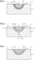
- FIG. 3 a second schematic sectional view of a cooling device 1 according to the invention with first fibers 9 of a fiber structure 8 and second fibers 12 of a further fiber structure 11 is shown.
- a heat pipe 3 of the cooling device 1 is mechanically connected to a heat sink 4 of the cooling device 1 via the first fibers 9 of the fiber structure 8 on the heat pipe surface 7 of the heat pipe 3 and the second fibers 12 of the further fiber structure 11 on the heat sink surface 10 of the heat sink 4.
- the heat pipe 3 is thereby supported by a groove recess 6, which is arranged on a first heat sink side 5 of the heat sink 4, partially enclosed, with the first and the second fibers 9,12 being arranged in the area of the enclosure.
- the mechanical connection is essentially a material connection (shown here greatly enlarged).
- the heat pipe 3 and the heat sink 4 form a flat surface on the first heat sink side 5 .
- the heat pipe 3 was mechanically connected to the heat sink 4 here by pressing the heat pipe 3 into the heat sink 4 on its first heat sink side 5, with the exertion of force during the pressing exerting its force mainly in the direction of the groove base 22 of the groove recess 6.
- In 3 shows the result of the compression in the form of an efficient mechanical/thermal connection of the heat pipe 3 to the heat sink 4, with the connection of the longer second fibers 12 at the groove edges 21 of the groove recess 6 with the first fibers 9 arranged there being at least equivalent in terms of mechanical stability and thermal resistance to the connection of the shorter second fibers 12 at the groove base 22 of the groove recess 6 with the first fibers 9 arranged there.
- FIG 4 shows a third schematic sectional view of a cooling device 1 according to the invention with a roughened surface structure 13 of a heat sink surface 10 of a heat sink 4.
- a heat pipe 3 of the cooling device 1 is mechanically connected to a heat sink 4 of the cooling device 1 via the first fibers 9 of the fiber structure 8 on the heat pipe surface 7 of the heat pipe 3 and the roughened surface structure 13 of the heat sink surface 10 of the heat sink 4 .
- the heat pipe 3 is partially surrounded by a groove recess 6, which is arranged on a first heat sink side 5 of the heat sink 4, the first fibers 9 and the roughened Surface structure 13 are arranged in the area of the enclosure.
- the mechanical connection is essentially a material connection (shown here greatly enlarged).
- the heat pipe 3 and the heat sink 4 form a flat surface on the first heat sink side 5 .
- the first fibers 9 of the heat pipe surface 7 of the heat pipe 3 have barbs 14 which further improve the enclosing or wedging of the roughened surface structure 13 of the heat sink surface 10 of the heat sink 4 .
- a fourth schematic sectional view in the 5 visualizes a cooling device 1 according to the invention with a heat sink surface 10 of a heat sink 4 penetrating first fibers 9.
- a heat pipe 3 of the cooling device 1 is mechanically connected to a heat sink 4 of the cooling device 1 via the first fibers 9 of the fiber structure 8 on the heat pipe surface 7 of the heat pipe 3, which penetrate the heat sink surface 10 of the heat sink 4.
- the heat pipe 3 is partially surrounded by a groove recess 6, which is arranged on a first heat sink side 5 of the heat sink 4, the first fibers 9 being arranged in the area of the enclosure.
- the mechanical connection is essentially a material connection (shown here greatly enlarged).
- the heat pipe 3 and the heat sink 4 form a flat surface on the first heat sink side 5 .
- the first fibers 9 of the heat pipe surface 7 of the heat pipe 3 have barbs 14 which are hooked at least in the heat sink surface 10 of the heat sink 4 .
- the first fibers 9 penetrate deeper into the basic structure of the heat sink 4 and are hooked there.
- FIG. 6 is a fifth schematic sectional view of a cooling device 1 according to the invention with a connection an electronic component 2 to the cooling device 1 is shown.
- a heat pipe 3 of the cooling device 1 is mechanically connected to a heat sink 4 of the cooling device 1 via the first fibers 9 of the fiber structure 8 on the heat pipe surface 7 of the heat pipe 3 and the second fibers 12 of the further fiber structure 11 on the heat sink surface 10 of the heat sink 4.
- the heat pipe 3 is thereby partially surrounded by a groove recess 6, which is arranged on a first heat sink side 5 of the heat sink 4, the first and the second fibers 9, 12 being arranged in the area of the enclosure.
- the mechanical connection is essentially a material connection (shown here greatly enlarged).
- the heat pipe 3 and the heat sink 4 form a flat surface on the first heat sink side 5 .
- the electronic component 2 is arranged above the heat pipe 3 on the planar surface of the first heat sink side 5 in such a way that it can be cooled during operation by means of the heat pipe 3 and the heat sink 4 .
- the heat sink 4 has heat sink ribs 20 on a second heat sink side 19 facing away from the first heat sink side 5 .
- these heat sink ribs 20 of the heat sink 4 support the heat dissipation of the electronic component 2 in combination with the heat pipe 3 by dissipating the heat loss of the electronic component 2 to the environment in an advantageous manner.
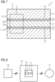
- FIG 7 shows a schematic representation of a plan view of the cooling device 1 according to the invention 6 .
- FIG 7 are the in 6 heatsink ribs shown cannot be seen, since the second heatsink side facing away from the first heatsink side 5 with those arranged there Heat sink fins are not shown for reasons of clarity.
- FIG 8 shows a converter 16 with the cooling device 1 according to the invention according to FIGS Figures 2 to 7 .
- the converter 16 is connected here to an electrical network 18 and an electrical machine 17 via three-phase electrical lines, for example, with the converter 16 supplying the electrical machine 17 with electrical energy from the electrical network 18 in general as a function of the torque and speed during operation.
- the electronic component 2 is arranged on a heat sink 4 and a heat pipe 3 integrated into the heat sink 4 of the cooling device 1 .
- the heat loss generated by the electronic component 2 during operation can then be conducted by means of the heat pipe 3 to cooler areas of the heat sink 4 and can be emitted mainly via the heat sink 4 to the environment inside or outside the converter 16 .
Landscapes
- Engineering & Computer Science (AREA)
- Microelectronics & Electronic Packaging (AREA)
- Physics & Mathematics (AREA)
- Thermal Sciences (AREA)
- Mechanical Engineering (AREA)
- General Engineering & Computer Science (AREA)
- Cooling Or The Like Of Electrical Apparatus (AREA)
- Cooling Or The Like Of Semiconductors Or Solid State Devices (AREA)
Description
- Die Erfindung betrifft eine Kühlvorrichtung zur Entwärmung eines elektronischen Bauelements, wobei die Kühlvorrichtung ein Wärmerohr und einen Kühlkörper umfasst und der Kühlkörper an einer ersten Kühlkörperseite verlaufend eine Nutaussparung aufweist, welche das Wärmerohr zumindest teilweise umschließt.
- In elektrischen Geräten der Antriebstechnik, wie beispielsweise Frequenzumrichtern, werden zur Entwärmung der im Betrieb auftretenden Verlustwärme insbesondere von elektronischen Bauelementen der Leistungselektronik im mittleren und höheren Leistungsbereich Wärmerohre, wie z.B. Heatpipes eingesetzt, wobei ein oder mehrere Wärmerohre die Verlustwärme in oder an beispielsweise einem Aluminiumkühlkörper gleichmäßig von der Wärmequelle weg an kühlere Stellen des Kühlkörpers verteilen und somit effizient abführen.
- Die Herstellung einer mechanisch stabilen und thermisch wirksamen Verbindung des Wärmerohres mit dem Kühlkörper ist ein aufwendiger und zeitintensiver Prozess. So steigen die Herstellungskosten eines Kühlkörpers mit einem implementierten Wärmerohr teilweise auf das Doppelte der Herstellung eines Kühlkörpers ohne Wärmerohr. Bei vielen elektrischen Geräten übersteigen diese Herstellungskosten des Kühlkörpers mit Wärmerohr das geplante Budget, mit der Folge, dass die Kühlkörper insbesondere bei erwartet hohen Verlustleistungen eher mit einem größeren Volumen dimensioniert werden. Die Nachteile sind jedoch, dass ein entsprechend größerer Bauraum in den elektrischen Geräten vorgehen werden muss und ein kompakterer Aufbau der elektrischen Geräte schwerer realisierbar ist.
- Um Wärmerohre in Kühlkörpern zu implementieren, werden die Wärmerohre in Kontaktflächen des Kühlkörpers derart eingebracht, dass beispielsweise für die Wärmerohre Nuten in den Kühlkörper eingearbeitet, also oftmals eingefräst werden, welche die Form und den Querschnitt des jeweiligen Wärmerohrs abbilden. Bevor das Wärmerohr unter Druck in die entsprechende Kühlkörpernut eingepresst wird, wird ein wärmeleitendes, meist als Klebstoff ausgeführtes Material in Form eines Wärmeleitklebers auf die Kühlkörpernut aufgebracht. Nach Verpressung des Wärmerohrs in die Nut des Kühlkörpers wird der Wärmeleitkleber getrocknet, damit diese wärmeleitende Klebstoffverbindung aushärtet. Anschließen wird die Oberfläche des Kühlkörpers mit dem verpressten Wärmerohr im Allgemeinen noch einmal überfräst, um die Materialunebenheiten und Reste des Wärmeleitklebers abzutragen.
- Nachteilig am Wärmeleitkleber ist seine - im Gegensatz beispielsweise zu Metallverbindungen aus Kupfer und/oder aus Aluminium - wesentlich schlechtere Wärmeleitfähigkeit, welche jedoch besser ist als beispielsweise die von teilweise in Verpressungshohlräumen auftretender eingeschlossener Luft. Derartige thermische Barrieren für einen Wärmetransport werden durch den Wärmeleitkleber zumindest verringert.
- Ein weiterer entscheidender Nachteil ist, dass nach oftmals kurzen Betriebszeiten der zwischen Kühlkörper und Wärmerohr eingebrachte Wärmeleitkleber verklumpen oder spröde werden kann. Der thermische Widerstand des Kühlkörpers wird dann zum Teil erheblich ansteigen und den Betrieb des zu entwärmenden elektronischen Bauteils in dem elektrischen Gerät gefährden bzw. das elektronische Bauteil und somit ggf. das gesamte elektrische Gerät zerstören.
- Die
US 2016/0265857 A1 bezieht sich auf Radiatoren, die in Raumfahrzeugen verwendet werden, um Wärme abzugeben. Typische Beispiele für wärmeableitende Komponenten sind beispielsweise Elektronik und Wanderfeldröhrenverstärker (TWTAs), die in Telekommunikationssatelliten verwendet werden. Die Radiatoren weisen ein Wärmeversorgungsgerät auf, welches beispielsweise als Wärmerohr ausgebildet ist, und mittels eines Klebematerials mit einer Wärmeleitschicht verbunden ist. - Die
DE 20 2015 101 819 U1 betrifft eine Befestigungsstruktur eines Wärmerohrs, mittels der das Wärmerohr ohne Schweißverbindung befestigt werden kann. Dabei umfasst die Befestigungsstruktur ein Wärmerohr, das einen Hauptkörper aufweist, der eine erste Seite und eine zweite Seite besitzt; einen Träger, der eine Nut aufweist, die eine offene Seite und eine geschlossene Seite besitzt, wobei das Wärmerohr in der Nut angeordnet ist, wobei die erste und zweite Seite des Wärmerohrs auf die offene Seite und die geschlossene Seite gerichtet sind; und ein erstes Befestigungselement, das auf dem Wärmerohr und dem Träger angeordnet ist, wobei eine Seite des ersten Befestigungselements mit der ersten Seite des Wärmerohrs in Kontakt steht. Dadurch kann die Erfindung die Probleme bei der Befestigung durch Schweißverbindung und Presspassung vermeiden. - Der Erfindung liegt daher die Aufgabe zugrunde, eine Kühlvorrichtung mit einem Wärmerohr und einem Kühlkörpern bereitzustellen, deren mechanisch/thermische Verbindung gegenüber dem Stand der Technik verbessert ist.
- Die Aufgabe wird durch eine Kühlvorrichtung mit den in Anspruch 1 angegebenen Merkmalen sowie durch einen Umrichter mit der Kühlvorrichtung nach den in Anspruch 13 angegebenen Merkmalen gelöst.
- Für die Lösung der Aufgabe wird eine Kühlvorrichtung vorgeschlagen, welche zur Entwärmung eines elektronischen Bauelements ein Wärmerohr und einen Kühlkörper umfasst, wobei der Kühlkörper an einer ersten Kühlkörperseite verlaufend eine Nutaussparung aufweist, welche das Wärmerohr zumindest teilweise umschließt, wobei eine Wärmerohroberfläche des Wärmerohrs im Bereich der Umschließung durch die Nutaussparung eine Faserstruktur aus ersten Fasern aufweist und wobei die ersten Fasern der Wärmerohroberfläche des Wärmerohrs im Bereich der Nutaussparung eine mechanische Verbindung mit einer Kühlkörperoberfläche des Kühlkörpers ausbilden.
- Durch die vorteilhafte Verwendung der ersten Fasern der Faserstruktur des Wärmerohrs, welche insbesondere ein Material wie das des Wärmerohrs aufweisen, wurden Spalten, welche bei einer Verpressung des Wärmerohrs in die Nutaussparung des Kühlkörpers im Allgemeinen im mikroskopischen Bereich entstehen können, aufgefüllt und somit überbrückt. Die während der Verpressung ausgeübte Druckkraft hat im Allgemeinen bewirkt, dass mittels der metallischen ersten Fasern die Wärmerohroberfläche des Wärmerohres mit der metallischen Kühlkörperoberfläche des Kühlkörpers in einer stoffschlüssigen unlösbaren oder zumindest eingeschränkt lösbare Verbindung verbunden ist. Die ersten Fasern sind dabei Bestandteil der Wärmerohroberfläche des Wärmerohrs.
- Somit kann auf den Einsatz eines Wärmeleitklebers für die mechanisch/thermischen Verbindung zwischen Wärmerohr und Kühlkörper in vorteilhafter Weise verzichtet werden, so dass das bekannte Verklumpen und spröde werden von Wärmeleitklebern keinen negativen Einfluss mehr auf den thermischen Widerstandswert der thermischen Verbindung zwischen Wärmerohr und Kühlkörper hat und hier auch eine mechanisch stabilere metallische Verbindung ausgeführt ist.
- Vorteilhafte Ausgestaltungsformen des modularen Umrichters sind in den abhängigen Ansprüchen angegeben.
- Bei einer ersten vorteilhaften Ausgestaltungsform der Kühlvorrichtung weist die erste Kühlkörperoberfläche im Bereich der Nutaussparung eine weitere Faserstruktur aus zweiten Fasern auf und bilden die ersten Fasern der Wärmerohroberfläche des Wärmerohrs im Bereich der Nutaussparung eine mechanische Verbindung mit den zweiten Fasern der Kühlkörperoberfläche des Kühlkörpers aus.
- Die Faserstruktur und die weitere Faserstruktur weisen jeweils mittels der ersten und zweiten Fasern eine bürstenähnliche Geometrie auf. Durch eine Verschlingung bzw. eine Verfilzung der ersten Fasern der Wärmerohroberfläche des Wärmerohrs mit den zweiten Fasern der Kühlkörperoberfläche des Kühlkörpers hat sich eine vorteilhaft mechanische wie auch thermische Verbindung der Wärmerohroberfläche mit der Kühlkörperoberfläche und somit des Wärmerohres mit dem Kühlkörper ausgebildet. Dies stärkt insbesondere die stoffschlüssige mechanische Verbindung des Wärmerohrs mit dem Kühlkörper und verbessert weiter deren thermische Kopplung.
- Die zweiten Fasern sind, soweit vorhanden, Bestandteil der Kühlkörperoberfläche des Kühlkörpers.
- Bei einer weiteren vorteilhaften Ausgestaltungsform der Kühlvorrichtung sind die zweiten Fasern, welche an den Nutränder der Nutaussparung angeordnet sind, länger, als die zweiten Fasern, welche am Nutgrund der Nutaussparung angeordnet sind.
- Diese Ausgestaltungsform berücksichtigt in vorteilhafter Weise, dass die Kraftausübung bei der Verpressung des Wärmerohrs mit dem Kühlkörper ihre Kraftwirkung hauptsächlich in Richtung Nutgrund ausübt. Damit ist die mechanisch/thermische Verbindung der längeren zweiten Fasern an den Nuträndern mit den dort angeordneten ersten Fasern zumindest gleichwertig bzgl. mechanischer Stabilität und thermischem Widerstandswert, wie die mechanisch/thermische Verbindung der kürzeren zweiten Fasern am Nutgrund mit den dort angeordneten ersten Fasern.
- Bei einer ebenfalls vorteilhaften Ausgestaltungsform der Kühlvorrichtung weist die erste Kühlkörperoberfläche im Bereich der Nutaussparung eine aufgeraute Oberflächenstruktur auf und bilden die ersten Fasern der Wärmerohroberfläche des Wärmerohrs eine mechanische Verbindung mit der aufgerauten Oberflächenstruktur der Kühlkörperoberfläche des Kühlkörpers im Bereich der Nutaussparung aus.
- Die ersten Fasern der Wärmerohroberfläche des Wärmerohrs umschlingen die aufgeraute Oberflächenstruktur bzw. verkeilen sich zwischen der aufgerauten Oberflächenstruktur der Kühlkörperoberfläche des Kühlkörpers und bilden eine vorteilhafte mechanische wie auch thermische Verbindung der Wärmerohroberfläche mit der Kühlkörperoberfläche und somit des Wärmerohres mit dem Kühlkörper.
- Bei einer weiteren vorteilhaften Ausgestaltungsform der Kühlvorrichtung durchdringen die ersten Fasern der Wärmerohroberfläche des Wärmerohrs die Kühlkörperoberfläche des Kühlkörpers im Bereich der Nutaussparung.
- Die ersten Fasern der Wärmerohroberfläche des Wärmerohrs dringen derart in die Kühlkörperoberfläche des Kühlkörpers ein, dass sie sich in vorteilhafter Weise insbesondere mechanisch stoffschlüssig mit der Kühlkörperoberfläche verbinden. Sie können darüber hinaus auch tiefer in die Grundstruktur des Kühlkörpers eindringen, was die mechanische und somit auch die thermische Verbindung des Wärmerohres mit dem Kühlkörper weiter verbessert.
- Bei einer ebenfalls vorteilhaften Ausgestaltungsform der Kühlvorrichtung weisen die ersten Fasern der Faserstruktur und, falls vorhanden, die zweiten Fasern der weiteren Faserstruktur oder die aufgeraute Oberflächenstruktur eine nanoskalige oder mikroskalige Struktur auf.
- Mittels dieser nanoskaligen oder mikroskaligen Struktur der ersten Fasern der Faserstruktur und, falls vorhanden, der zweiten Fasern der weiteren Faserstruktur sind Verpressungshohlräume mit z.B. Lufteinschlüssen, welche aufgrund der Verpressung des Wärmerohres in den Kühlkörper entstehen könnten, in vorteilhafter Weise mit metallischem Material der Fasern feingranular aufgefüllt, so dass insbesondere der thermische Widerstand der thermischen Verbindung des Wärmerohres mit dem Kühlkörper gegenüber der Einbringung eines Wärmeleitklebers weiter verbessert wird. Unter nanoskaligen oder mikroskaligen Strukturen werden Abmessungen von Körpern bzw. Strukturen verstanden, welche in einem nanoskaligen Bereich von Nanometern oder in einem mikroskaligen Bereich von Mikrometern nur unter starker Vergrößerung für das menschliche Auge sichtbar werden.
- Bei einer weiteren vorteilhaften Ausgestaltungsform der Kühlvorrichtung weisen die ersten Fasern Widerhaken und, falls vorhanden, die zweiten Fasern Ösen auf.
- Mittels der Widerhaken ist eine mechanische Verbindung der ersten Fasern mit der Kühlkörperoberfläche hergestellt, welche kaum noch zerstörungsfrei trennbar ist. Falls die zweiten Fasern an der Kühlkörperoberfläche vorhanden sind, bilden die Widerhaken und die Ösen, in welchen die Widerhaken verankert sind, eine verbesserte, stabilere mechanische Verbindung. Unter Ösen werden auch Öffnungen in den zweiten Fasern verstanden, welche bei der Verpressung des Wärmerohres in den Kühlkörper unter Durchstoßen von Widerhaken durch die zweiten Fasern ausgebildet sind. Verbindungen, welche Fasern mit Widerhaken und Ösen aufweisen, werden auch als Klettverschlüsse bezeichnet.
- Bei einer ebenfalls vorteilhaften Ausgestaltungsform der Kühlvorrichtung sind die ersten Fasern und, falls vorhanden, die zweiten Fasern durch Materialbeschichtung oder durch Materialabtrag ausgebildet.
- Sind die ersten Fasern und, falls vorhanden, die zweiten Fasern durch Materialbeschichtung ausgebildet, kann deren Material von dem Material des Wärmerohres bzw. des Kühlköpers abweichen. Vorteilhaft ist hier die Abweichung des Materials der zweiten Fasern der Kühlkörperoberfläche vom Material des Kühlkörpers, also vom Material der Grundstruktur des Kühlkörpers. Der Kühlkörper kann dazu aus Aluminium oder aus einer Aluminiumlegierung bestehen, während die Kühlkörperoberfläche mit den zweiten Fasern beispielsweise aus Kupfer oder einer Kupferlegierung besteht. Sind die ersten Fasern der Wärmerohroberfläche des Wärmerohrs dann beispielsweise ebenfalls aus Kupfer, ist eine sehr gute mechanisch stoffschlüssige Verbindung mit einer sehr guten thermischen Wärmeleitfähigkeit ausgebildet.
- Bei einer weiteren vorteilhaften Ausgestaltungsform der Kühlvorrichtung bestehen die ersten Fasern der Wärmerohroberfläche des Wärmerohrs und, falls vorhanden, die zweiten Fasern der Kühlkörperoberfläche des Kühlkörpers aus Kupfer oder aus einer Kupferlegierung.
- Das Kupfer bzw. die Kupferlegierung ist für die thermische Verbindung der ersten Fasern der Wärmerohroberfläche des Wärmerohrs mit der Kühlkörperoberfläche des Kühlkörpers und, falls vorhanden, mit den zweiten Fasern der Kühlkörperoberfläche des Kühlkörpers ein gut geeignetes Material, da hier der thermische Widerstand dieser mechanisch/thermischen Verbindung vorteilhaft reduziert ist gegenüber beispielsweise einer Verbindung unter Einsatz eines Wärmeleitklebers oder gegenüber beispielsweise einer Verbindung bestehend aus Aluminium und Kupfer.
- Bei einer ebenfalls vorteilhaften Ausgestaltungsform der Kühlvorrichtung ist das Material der ersten Fasern des Wärmerohrs mechanisch härter als das Material der Kühlkörperoberfläche des Kühlkörpers.
- Da das Material der ersten Fasern in vorteilhafter Weise härter ist, als das Material der Kühlkörperoberfläche des Kühlkörpers, ist die Kühlkörperoberfläche intensiv von den ersten Fasern durchdrungen, was die Stabilität der mechanischen Verbindung erhöht, insbesondere auch dann, wenn die ersten Fasern über Widerhaken verfügen. Ferner können die ersten Fasern noch besser über die Kühlkörperoberfläche in die Grundstruktur des Kühlkörper eindringen.
- Bei einer weiteren vorteilhaften Ausgestaltungsform der Kühlvorrichtung ist das Wärmerohr eine Heatpipe.
- Die Nutzung einer Heatpipe als Wärmerohr in der Kühlvorrichtung hat den Vorteil, dass Heatpipes sowohl in horizontaler wie auch in vertikaler Einbaulage eingesetzt werden können, im Gegensatz zu Zwei-Phasen-Thermosiphons, welche schwerkraftgetrieben sind. Ferner sind die Bezugskosten von Heatpipes auch für die Entwärmung von elektronischen Bauelementen höherer Leistungsklassen eher gering, da sie als Massenartikel hergestellt werden, wobei die Kühlvorrichtung dann ebenfalls preisgünstig angeboten werden kann.
- Bei einer ebenfalls vorteilhaften Ausgestaltungsform der Kühlvorrichtung weist der Kühlkörper an einer von der ersten Kühlkörperseite abgewandten zweiten Kühlkörperseite Kühlkörperrippen auf.
- Die Kühlkörperrippen am Kühlkörper unterstützen in Kombination mit dem Wärmerohr die Entwärmung von elektronischen Bauelementen im Betrieb, indem deren Verlustwärme in vorteilhafter Weise an die Umgebung abgegeben werden kann.
- Für die Lösung der Aufgabe wird ferner ein Umrichter zum Betrieb einer elektrischen Maschine an einem elektrischen Netz mit der erfindungsgemäßen Kühlvorrichtung und einem elektronischen Bauelement vorgeschlagen, wobei das elektronische Bauelement mit einem Kühlkörper der Kühlvorrichtung im Bereich eines von dem Kühlkörper zumindest teilweise umschlossenen Wärmerohrs der Kühlvorrichtung mechanisch verbunden ist.
- Im Betrieb des Umrichters bzw. beim Betrieb des elektronischen Bauelements wird die dort erzeugte Verlustwärme in vorteilhafter Weise mittels des in den Kühlkörper integrierten Wärmerohrs von dem elektronischen Bauelement weggeleitet und von dem Kühlkörper an die Umgebung abgegeben.
- Bei einer vorteilhaften Ausgestaltungsform des Umrichters ist der Kühlkörper als ein Umrichtergehäuse oder als ein Teil eines Umrichtergehäuses ausgebildet.
- Die Kühlvorrichtung, also der Kühlkörper mit dem integrierten Wärmerohr, kann hier aus Sicht der räumlichen Anordnung und Ausdehnung in vorteilhafter Weise für den Umrichter angeordnet werden, wobei vorhandene oder erforderliche bauliche Strukturen des Umrichters, also das Umrichtergehäuses benutzt werden.
- Bei einer weiteren vorteilhaften Ausgestaltungsform des Umrichters ist das elektronische Bauelement ein Leistungshalbleiter oder ein Leistungshalbleitermodul.
- So kann das Leistungshalbleitermodul eine Vielzahl von Leistungshalbleitern aufweisen, welche im Betrieb des Umrichters bzw. des Leistungshalbleitermoduls mittels der Kühlvorrichtung entwärmt werden.
- Die oben beschriebenen Eigenschaften, Merkmale und Vorteile dieser Erfindung sowie die Art und Weise, wie diese erreicht werden, werden klarer und deutlicher verständlich im Zusammenhang mit der folgenden Beschreibung der Ausführungsbeispiele, die im Zusammenhang mit den Figuren näher erläutert werden. Es zeigt:
- FIG 1
- eine schematische Darstellung einer Metallfaserstruktur auf einer Oberfläche eines Metallkörpers,
- FIG 2
- eine erste schematische Schnittdarstellung einer erfindungsgemäßen Kühlvorrichtung mit ersten Fasern einer Faserstruktur und zweiten Fasern einer weiteren Faserstruktur,
- FIG 3
- eine zweite schematische Schnittdarstellung einer erfindungsgemäßen Kühlvorrichtung mit ersten Fasern einer Faserstruktur und zweiten Fasern einer weiteren Faserstruktur,
- FIG 4
- eine dritte schematische Schnittdarstellung einer erfindungsgemäßen Kühlvorrichtung mit einer aufgerauten Oberflächenstruktur einer Kühlkörperoberfläche eines Kühlkörpers,
- FIG 5
- eine vierte schematische Schnittdarstellung einer erfindungsgemäßen Kühlvorrichtung mit eine Kühlkörperoberfläche eines Kühlkörpers durchdringenden ersten Fasern,
- FIG 6
- eine fünfte schematische Schnittdarstellung einer erfindungsgemäßen Kühlvorrichtung mit einer Anbindung eines elektronischen Bauelements an die Kühlvorrichtung,
- FIG 7
- eine schematische Darstellung der Draufsicht auf die erfindungsgemäße Kühlvorrichtung nach
FIG 6 und - FIG 8
- eine schematische Darstellung eines Umrichters mit der erfindungsgemäßen Kühlvorrichtung nach den Figuren 2 bis 7.
- Die
FIG 1 zeigt eine schematische Darstellung einer Metallfaserstruktur 26 auf einer Oberfläche 24 eines Metallkörpers 23. Die Metallfaserstruktur 26 weist dabei Metallfasern 25 auf, welche im Wesentlichen senkrecht von der Oberfläche 24 des Metallkörpers 23 abstehen. Die schematische Darstellung derFIG 1 ist dabei stark vergrößert, da hier die Metallfasern 25 der Metallfaserstruktur 26 im nanoskaligen oder mikroskaligen Bereich ausgebildet sind. - Alle im folgenden beschriebenen
Figuren 2 bis 7 sind in ihrer schematischen Darstellung stark vergrößert und zeigen eine Kühlvorrichtung 1 in einem insbesondere nanoskaligen oder mikroskaligen Bereich mit einer mechanischen/thermischen Verbindung eines Wärmerohres 2 mit einem Kühlkörper 4. - In
FIG 2 wird eine erste schematische Schnittdarstellung einer erfindungsgemäßen Kühlvorrichtung 1 mit ersten Fasern 9 einer Faserstruktur 8 und zweiten Fasern 12 einer weiteren Faserstruktur 11 aufgezeigt. - Ein Wärmerohr 3 der Kühlvorrichtung 1 ist mit einem Kühlkörper 4 der Kühlvorrichtung 1 über die ersten Fasern 9 der Faserstruktur 8 an der Wärmerohroberfläche 7 des Wärmerohres 3 und die zweiten Fasern 12 der weiteren Faserstruktur 11 an der Kühlkörperoberfläche 10 des Kühlkörpers 4 mechanisch verbunden. Das Wärmerohr 3 wird dabei von einer Nutaussparung 6, welche an einer ersten Kühlkörperseite 5 des Kühlkörpers 4 angeordnet ist, teilweise umschlossen, wobei die ersten und die zweiten Fasern 9,12 im Bereich der Umschließung angeordnet sind. Die mechanische Verbindung ist im Wesentlichen eine stoffschlüssige Verbindung (hier stark vergrößert dargestellt). Das Wärmerohr 3 und der Kühlkörper 4 bilden an der ersten Kühlkörperseite 5 des Kühlkörpers 4 eine plane Fläche aus.
- Die ersten Fasern 9 weisen ferner Widerhaken 14 und die zweiten Fasern 12 Ösen 15 auf, wobei sich die Widerhaken 14 der ersten Fasern 9 mit den Ösen 15 der zweiten Fasern 12 mechanisch verbinden (hier nur andeutungsweise in
FIG 2 visualisiert). Diese Verbindung ist mechanisch sehr stabil und kann als Klettverschlussverbindung bezeichnet werden. - Mit der
FIG 3 wird eine zweite schematische Schnittdarstellung einer erfindungsgemäßen Kühlvorrichtung 1 mit ersten Fasern 9 einer Faserstruktur 8 und zweiten Fasern 12 einer weiteren Faserstruktur 11 aufgezeigt. - Ein Wärmerohr 3 der Kühlvorrichtung 1 ist mit einem Kühlkörper 4 der Kühlvorrichtung 1 über die ersten Fasern 9 der Faserstruktur 8 an der Wärmerohroberfläche 7 des Wärmerohres 3 und die zweiten Fasern 12 der weiteren Faserstruktur 11 an der Kühlkörperoberfläche 10 des Kühlkörpers 4 mechanisch verbunden. Das Wärmerohr 3 wird dabei von einer Nutaussparung 6, welche an einer ersten Kühlkörperseite 5 des Kühlkörpers 4 angeordnet ist, teilweise umschlossen, wobei die ersten und die zweiten Fasern 9,12 im Bereich der Umschließung angeordnet sind. Die mechanische Verbindung ist im Wesentlichen eine stoffschlüssige Verbindung (hier stark vergrößert dargestellt). Das Wärmerohr 3 und der Kühlkörper 4 bilden an der ersten Kühlkörperseite 5 eine plane Fläche aus.
- Die mechanische Verbindung des Wärmerohrs 3 mit dem Kühlkörper 4 erfolgte hier mittels Verpressung des Wärmerohrs 3 in den Kühlkörper 4 an dessen erster Kühlkörperseite 5, wobei die Kraftausübung bei der Verpressung ihre Kraftwirkung hauptsächlich in Richtung des Nutgrunds 22 der Nutaussparung 6 ausübt.
- In
FIG 3 ist das Ergebnis der Verpressung in Form einer effizienten mechanisch/thermischen Verbindung des Wärmerohres 3 mit dem Kühlkörper 4 dargestellt, wobei die Verbindung der längeren zweiten Fasern 12 an den Nuträndern 21 der Nutaussparung 6 mit den dort angeordneten ersten Fasern 9 zumindest gleichwertig bzgl. der mechanischen Stabilität und des thermischem Widerstandswert ist, wie die Verbindung der kürzeren zweiten Fasern 12 am Nutgrund 22 der Nutaussparung 6 mit den dort angeordneten ersten Fasern 9. - Die
FIG 4 zeigt eine dritte schematische Schnittdarstellung einer erfindungsgemäßen Kühlvorrichtung 1 mit einer aufgerauten Oberflächenstruktur 13 einer Kühlkörperoberfläche 10 eines Kühlkörpers 4. - Ein Wärmerohr 3 der Kühlvorrichtung 1 ist mit einem Kühlkörper 4 der Kühlvorrichtung 1 über die ersten Fasern 9 der Faserstruktur 8 an der Wärmerohroberfläche 7 des Wärmerohres 3 und die aufgeraute Oberflächenstruktur 13 der Kühlkörperoberfläche 10 des Kühlkörpers 4 mechanisch verbunden. Das Wärmerohr 3 wird dabei von einer Nutaussparung 6, welche an einer ersten Kühlkörperseite 5 des Kühlkörpers 4 angeordnet ist, teilweise umschlossen, wobei die ersten Fasern 9 und die aufgeraute Oberflächenstruktur 13 im Bereich der Umschließung angeordnet sind. Die mechanische Verbindung ist im Wesentlichen eine stoffschlüssige Verbindung (hier stark vergrößert dargestellt). Das Wärmerohr 3 und der Kühlkörper 4 bilden an der ersten Kühlkörperseite 5 eine plane Fläche aus.
- Die ersten Fasern 9 der Wärmerohroberfläche 7 des Wärmerohrs 3 weisen Widerhaken 14 auf, welche die Umschließung bzw. die Verkeilung der aufgerauten Oberflächenstruktur 13 der Kühlkörperoberfläche 10 des Kühlkörpers 4 weiter verbessern.
- Eine vierte schematische Schnittdarstellung in der
FIG 5 visualisiert eine erfindungsgemäße Kühlvorrichtung 1 mit eine Kühlkörperoberfläche 10 eines Kühlkörpers 4 durchdringenden ersten Fasern 9. - Ein Wärmerohr 3 der Kühlvorrichtung 1 ist mit einem Kühlkörper 4 der Kühlvorrichtung 1 über die ersten Fasern 9 der Faserstruktur 8 an der Wärmerohroberfläche 7 des Wärmerohres 3, welche die Kühlkörperoberfläche 10 des Kühlkörpers 4 durchdringen, mechanisch verbunden. Das Wärmerohr 3 wird dabei von einer Nutaussparung 6, welche an einer ersten Kühlkörperseite 5 des Kühlkörpers 4 angeordnet ist, teilweise umschlossen, wobei die ersten Fasern 9 im Bereich der Umschließung angeordnet sind. Die mechanische Verbindung ist im Wesentlichen eine stoffschlüssige Verbindung (hier stark vergrößert dargestellt). Das Wärmerohr 3 und der Kühlkörper 4 bilden an der ersten Kühlkörperseite 5 eine plane Fläche aus.
- Die ersten Fasern 9 der Wärmerohroberfläche 7 des Wärmerohrs 3 weisen Widerhaken 14 auf, welche zumindest in der Kühlkörperoberfläche 10 des Kühlkörpers 4 verhakt sind. In der
FIG 5 ist darüber hinaus dargestellt, dass die ersten Fasern 9 tiefer in die Grundstruktur des Kühlkörpers 4 eindringen und dort verhakt sind. - In der
FIG 6 wird eine fünfte schematische Schnittdarstellung einer erfindungsgemäßen Kühlvorrichtung 1 mit einer Anbindung eines elektronischen Bauelements 2 an die Kühlvorrichtung 1 dargestellt. - Ein Wärmerohr 3 der Kühlvorrichtung 1 ist mit einem Kühlkörper 4 der Kühlvorrichtung 1 über die ersten Fasern 9 der Faserstruktur 8 an der Wärmerohroberfläche 7 des Wärmerohres 3 und die zweiten Fasern 12 der weiteren Faserstruktur 11 an der Kühlkörperoberfläche 10 des Kühlkörpers 4 mechanisch verbunden. Das Wärmerohr 3 wird dabei von einer Nutaussparung 6, welche an einer ersten Kühlkörperseite 5 des Kühlkörpers 4 angeordnet ist, teilweise umschlossen, wobei die ersten und die zweiten Fasern 9,12 sind im Bereich der Umschließung angeordnet sind. Die mechanische Verbindung ist im Wesentlichen eine stoffschlüssige Verbindung (hier stark vergrößert dargestellt). Das Wärmerohr 3 und der Kühlkörper 4 bilden an der ersten Kühlkörperseite 5 eine plane Fläche aus.
- An der planen Fläche der ersten Kühlkörperseite 5 ist das elektronische Bauelement 2 über dem Wärmerohr 3 derart anordnet, damit es im Betrieb mittels des Wärmerohrs 3 und des Kühlkörpers 4 entwärmbar ist.
- Der Kühlkörper 4 weist an einer von der ersten Kühlkörperseite 5 abgewandten zweiten Kühlkörperseite 19 Kühlkörperrippen 20 auf. Diese Kühlkörperrippen 20 des Kühlkörpers 4 unterstützen im Betrieb die Entwärmung des elektronischen Bauelements 2 in Kombination mit dem Wärmerohr 3, indem sie die Verlustwärme des elektronischen Bauelements 2 in vorteilhafter Weise an die Umgebung abgegeben.
- Die
FIG 7 zeigt in einer schematischen Darstellung eine Draufsicht auf die erfindungsgemäße Kühlvorrichtung 1 nachFIG 6 . - Der
FIG 7 sind jedoch die inFIG 6 gezeigten Kühlkörperrippen nicht zu entnehmen, da die von der ersten Kühlkörperseite 5 abgewandte zweite Kühlkörperseite mit den dort angeordneten Kühlkörperrippen aus Gründen der Übersichtlichkeit nicht dargestellt werden. - In
FIG 8 zeigt in einer schematischen Darstellung einen Umrichter 16 mit der erfindungsgemäßen Kühlvorrichtung 1 nach denFiguren 2 bis 7 . - Der Umrichter 16 ist hier beispielhaft über jeweils dreiphasige elektrische Drehstromleitungen mit einem elektrischen Netz 18 und einer elektrischen Maschine 17 verbunden, wobei der Umrichter 16 im Betrieb die elektrische Maschine 17 im Allgemeinen moment- und drehzahlabhängig mit elektrischer Energie aus dem elektrischen Netz 18 versorgt.
- Das elektronische Bauelement 2 ist an einem Kühlkörper 4 und einem in den Kühlkörper 4 integrierten Wärmerohr 3 der Kühlvorrichtung 1 angeordnet. Die im Betrieb von dem elektronischen Bauelement 2 erzeugte Verlustwärme ist dann mittels des Wärmerohrs 3 an kühlere Bereiche des Kühlkörpers 4 leitbar und hauptsächlich über den Kühlkörper 4 an die Umgebung innerhalb oder außerhalb des Umrichters 16 abgebbar.
Claims (15)
- Kühlvorrichtung (1) zur Entwärmung eines elektronischen Bauelements (2), umfassend ein Wärmerohr (3) und einen Kühlkörper (4), wobei- der Kühlkörper (4) an einer ersten Kühlkörperseite (5) verlaufend eine Nutaussparung (6) aufweist, welche das Wärmerohr (3) zumindest teilweise umschließt, dadurch gekennzeichnet dass- eine Wärmerohroberfläche (7) des Wärmerohrs (3) im Bereich der Umschließung durch die Nutaussparung (6) eine Faserstruktur (8) aus ersten Fasern (9) aufweist und- die ersten Fasern (9) der Wärmerohroberfläche (7) des Wärmerohrs (3) im Bereich der Nutaussparung (6) eine mechanische Verbindung mit einer Kühlkörperoberfläche (10) des Kühlkörpers (4) ausbilden.
- Kühlvorrichtung (1) nach Anspruch 1, wobei die erste Kühlkörperoberfläche (10) im Bereich der Nutaussparung (6) eine weitere Faserstruktur (11) aus zweiten Fasern (12) aufweist und die ersten Fasern (9) der Wärmerohroberfläche (7) des Wärmerohrs (3) im Bereich der Nutaussparung (6) eine mechanische Verbindung mit den zweiten Fasern (12) der Kühlkörperoberfläche (10) des Kühlkörpers (4) ausbilden.
- Kühlvorrichtung (1) nach Anspruch 2, wobei die zweiten Fasern (12), welche an den Nutränder (21) der Nutaussparung (6) angeordnet sind, länger sind, als die zweiten Fasern (12), welche am Nutgrund (22) der Nutaussparung (6) angeordnet sind.
- Kühlvorrichtung (1) nach Anspruch 1, wobei die erste Kühlkörperoberfläche (10) im Bereich der Nutaussparung (6) eine aufgeraute Oberflächenstruktur (13) aufweist und die ersten Fasern (9) der Wärmerohroberfläche (7) des Wärmerohrs (3) eine mechanische Verbindung mit der aufgerauten Oberflächenstruktur (13) der Kühlkörperoberfläche (10) des Kühlkörpers (4) im Bereich der Nutaussparung (6) ausbilden.
- Kühlvorrichtung (1) nach Anspruch 1, wobei die ersten Fasern (9) der Wärmerohroberfläche (7) des Wärmerohrs (3) die Kühlkörperoberfläche (10) des Kühlkörpers (4) im Bereich der Nutaussparung (6) durchdringen.
- Kühlvorrichtung (1) nach einem der vorhergehenden Ansprüche, wobei die ersten Fasern (9) der Faserstruktur und, falls vorhanden, die zweiten Fasern (12) der weiteren Faserstruktur oder die aufgeraute Oberflächenstruktur (13) eine nanoskalige oder mikroskalige Struktur aufweisen.
- Kühlvorrichtung (1) nach einem der vorhergehenden Ansprüche, wobei die ersten Fasern (9) Widerhaken (14) und, falls vorhanden, die zweiten Fasern (12) Ösen (15) aufweisen.
- Kühlvorrichtung (1) nach einem der vorhergehenden Ansprüche, wobei die ersten Fasern (9) und, falls vorhanden, die zweiten Fasern (12) durch Materialbeschichtung oder durch Materialabtrag ausgebildet sind.
- Kühlvorrichtung (1) nach einem der vorhergehenden Ansprüche, wobei ersten Fasern (9) der Wärmerohroberfläche (7) des Wärmerohrs (3) und, falls vorhanden, die zweiten Fasern (12) der Kühlkörperoberfläche (10) des Kühlkörpers (4) aus Kupfer oder aus einer Kupferlegierungen bestehen.
- Kühlvorrichtung (1) nach einem der vorhergehenden Ansprüche, wobei das Material der ersten Fasern (9) des Wärmerohrs (3) mechanisch härter ist als das Material der Kühlkörperoberfläche (10) des Kühlkörpers (4).
- Kühlvorrichtung (1) nach einem der vorhergehenden Ansprüche, wobei das Wärmerohr (3) eine Heatpipe ist.
- Kühlvorrichtung (1) nach einem der vorhergehenden Ansprüche, wobei der Kühlkörper (4) an einer von der ersten Kühlkörperseite (5) abgewandten zweiten Kühlkörperseite (19) Kühlkörperrippen (20) aufweist.
- Umrichter (16) zum Betrieb einer elektrischen Maschine (17) an einem elektrischen Netz (18) mit einer Kühlvorrichtung (1) nach einem der Ansprüche 1 bis 12 und einem elektronischen Bauelement (2), wobei das elektronische Bauelement (2) mit einem Kühlkörper (4) der Kühlvorrichtung (1) im Bereich eines von dem Kühlkörper (4) zumindest teilweise umschlossenen Wärmerohrs (3) der Kühlvorrichtung (1) mechanisch verbunden ist.
- Umrichter (16) nach Anspruch 13, wobei der Kühlkörper (4) als Umrichtergehäuse oder als Teil eines Umrichtergehäuses ausgebildet ist.
- Umrichter (16) nach Anspruch 13 oder 14, wobei das elektronische Bauelement (2) ein Leistungshalbleiter oder ein Leistungshalbleitermodul ist.
Applications Claiming Priority (2)
| Application Number | Priority Date | Filing Date | Title |
|---|---|---|---|
| EP18204081.6A EP3648157A1 (de) | 2018-11-02 | 2018-11-02 | Kühlvorrichtung |
| PCT/EP2019/079796 WO2020089377A1 (de) | 2018-11-02 | 2019-10-31 | Kühlvorrichtung |
Publications (2)
| Publication Number | Publication Date |
|---|---|
| EP3824495A1 EP3824495A1 (de) | 2021-05-26 |
| EP3824495B1 true EP3824495B1 (de) | 2023-07-26 |
Family
ID=64183856
Family Applications (2)
| Application Number | Title | Priority Date | Filing Date |
|---|---|---|---|
| EP18204081.6A Withdrawn EP3648157A1 (de) | 2018-11-02 | 2018-11-02 | Kühlvorrichtung |
| EP19801748.5A Active EP3824495B1 (de) | 2018-11-02 | 2019-10-31 | Kühlvorrichtung |
Family Applications Before (1)
| Application Number | Title | Priority Date | Filing Date |
|---|---|---|---|
| EP18204081.6A Withdrawn EP3648157A1 (de) | 2018-11-02 | 2018-11-02 | Kühlvorrichtung |
Country Status (4)
| Country | Link |
|---|---|
| US (1) | US11723177B2 (de) |
| EP (2) | EP3648157A1 (de) |
| CN (1) | CN112997302B (de) |
| WO (1) | WO2020089377A1 (de) |
Family Cites Families (19)
| Publication number | Priority date | Publication date | Assignee | Title |
|---|---|---|---|---|
| US3585569A (en) * | 1969-09-02 | 1971-06-15 | Gen Electric | Electrical contact closure |
| JPS56138688A (en) * | 1980-03-31 | 1981-10-29 | Sumitomo Electric Ind Ltd | Heat pipe and manufacture thereof |
| CA2120645C (en) * | 1993-12-21 | 2004-02-10 | Andrew Scott Burnes | Compressively resilient loop structure for hook and loop fastener systems |
| AU2001234851A1 (en) * | 2000-03-08 | 2001-09-17 | Thermal Corp. | Matrix heat sink with extending fibers |
| CN2648603Y (zh) * | 2003-08-28 | 2004-10-13 | 李非亚 | 一种新型散热器 |
| US20050167083A1 (en) * | 2004-01-29 | 2005-08-04 | Belady Christian L. | Heat sink including redundant fan sinks |
| JP4714638B2 (ja) * | 2006-05-25 | 2011-06-29 | 富士通株式会社 | ヒートシンク |
| US8353334B2 (en) * | 2007-12-19 | 2013-01-15 | Teledyne Scientific & Imaging, Llc | Nano tube lattice wick system |
| EP2209173B1 (de) * | 2009-01-20 | 2012-06-06 | Innovavent GmbH | Lasergehäuse mit einem zu kühlenden Körper |
| EP2398132B1 (de) * | 2010-06-18 | 2019-02-20 | Grundfos Management A/S | Pumpenaggregat |
| JP5772614B2 (ja) * | 2011-06-27 | 2015-09-02 | 東芝ホームテクノ株式会社 | 冷却器 |
| DE202014101286U1 (de) * | 2014-03-20 | 2014-05-16 | Wischemann Kunststoff Gmbh | Flauschfolie einer Flächenheizung |
| CN203984869U (zh) * | 2014-08-11 | 2014-12-03 | 惠州智科实业有限公司 | 一种太阳花型热管散热器 |
| US10101099B2 (en) * | 2015-03-12 | 2018-10-16 | Airbus Defence And Space Netherlands B.V. | Radiator, as well as space vehicle structure comprising such radiator |
| DE202015101819U1 (de) * | 2015-04-14 | 2015-07-01 | Asia Vital Components Co., Ltd. | Befestigungsstruktur eines Wärmerohrs |
| DE102015219867A1 (de) * | 2015-10-13 | 2017-04-13 | Lenze Drives Gmbh | Platine, B-Lagerschild, Motorbausatz und Elektromotor |
| US20170156240A1 (en) * | 2015-11-30 | 2017-06-01 | Abb Technology Oy | Cooled power electronic assembly |
| US10012445B2 (en) * | 2016-09-08 | 2018-07-03 | Taiwan Microloops Corp. | Vapor chamber and heat pipe combined structure |
| EP3367431A1 (de) * | 2017-02-28 | 2018-08-29 | Siemens Aktiengesellschaft | Kühlvorrichtung zur entwärmung eines leistungshalbleitermoduls |
-
2018
- 2018-11-02 EP EP18204081.6A patent/EP3648157A1/de not_active Withdrawn
-
2019
- 2019-10-31 CN CN201980072572.1A patent/CN112997302B/zh active Active
- 2019-10-31 WO PCT/EP2019/079796 patent/WO2020089377A1/de not_active Ceased
- 2019-10-31 US US17/290,587 patent/US11723177B2/en active Active
- 2019-10-31 EP EP19801748.5A patent/EP3824495B1/de active Active
Also Published As
| Publication number | Publication date |
|---|---|
| CN112997302B (zh) | 2025-02-14 |
| EP3824495A1 (de) | 2021-05-26 |
| WO2020089377A1 (de) | 2020-05-07 |
| US20220007543A1 (en) | 2022-01-06 |
| EP3648157A1 (de) | 2020-05-06 |
| CN112997302A (zh) | 2021-06-18 |
| US11723177B2 (en) | 2023-08-08 |
Similar Documents
| Publication | Publication Date | Title |
|---|---|---|
| DE3932079C2 (de) | Kühlvorrichtung für elektronische Einrichtungen | |
| DE69922838T2 (de) | Kühlkörper für ein elektronisches bauelement,vorrichtung und verfahren zu dessen herstellung | |
| DE102008016960B4 (de) | Leistungshalbleitervorrichtung mit einem darin befestigten Modul | |
| DE102006001792B4 (de) | Halbleitermodul mit Halbleiterchipstapel und Verfahren zur Herstellung desselben | |
| DE4445541A1 (de) | Kühlkörperbefestigungseinrichtung | |
| DE19715001A1 (de) | Kühleinrichtung für einen Montagemodul | |
| EP3565394B1 (de) | Elektronikeinheit | |
| DE112014005694T5 (de) | Halbleitermodul | |
| EP0718886B1 (de) | Leistungshalbleitermodul | |
| DE202013002411U1 (de) | Wärmeverteiler mit Flachrohrkühlelement | |
| EP2439775B1 (de) | Wärmeverteiler mit mechanisch gesichertem Wärmekopplungselement | |
| EP3611779A1 (de) | Batteriesystem für ein kraftfahrzeug | |
| EP3459110A1 (de) | Kühldoseneinheit und leistungselektronische einrichtung mit kühldoseneinheit | |
| DE60020509T2 (de) | Elektronische baugruppe mit einer wärmeplatte | |
| DE102004035810A1 (de) | Kondensatormodul | |
| DE4311839A1 (de) | Mikrokühleinrichtung für eine Elektronik-Komponente | |
| DE19860322B4 (de) | Anordnung zur Abführung von in einem PTC-Element entstehender Wärme | |
| DE102005051269B3 (de) | Verbundwerkstoff und Bodenplatte | |
| EP3648157A1 (de) | Kühlvorrichtung | |
| DE112020004722T5 (de) | Leistungshalbleitervorrichtung und herstellungsverfahren für leistungshalbleitervorrichtung | |
| DE602004002249T2 (de) | Gestapelter Speicher und Herstellungsverfahren | |
| DE19904279B4 (de) | Halbleitervorrichtung | |
| DE102015120100B4 (de) | Elektronisches Modul, Verfahren zur Herstellung eines elektronischen Moduls und Zusammenstellung von übereinandergestapelten elektronischen Modulen | |
| DE202004006870U1 (de) | Leiterplatte | |
| DE102010002434B4 (de) | Temperiersystem |
Legal Events
| Date | Code | Title | Description |
|---|---|---|---|
| STAA | Information on the status of an ep patent application or granted ep patent |
Free format text: STATUS: UNKNOWN |
|
| STAA | Information on the status of an ep patent application or granted ep patent |
Free format text: STATUS: THE INTERNATIONAL PUBLICATION HAS BEEN MADE |
|
| PUAI | Public reference made under article 153(3) epc to a published international application that has entered the european phase |
Free format text: ORIGINAL CODE: 0009012 |
|
| STAA | Information on the status of an ep patent application or granted ep patent |
Free format text: STATUS: REQUEST FOR EXAMINATION WAS MADE |
|
| 17P | Request for examination filed |
Effective date: 20210222 |
|
| AK | Designated contracting states |
Kind code of ref document: A1 Designated state(s): AL AT BE BG CH CY CZ DE DK EE ES FI FR GB GR HR HU IE IS IT LI LT LU LV MC MK MT NL NO PL PT RO RS SE SI SK SM TR |
|
| DAV | Request for validation of the european patent (deleted) | ||
| DAX | Request for extension of the european patent (deleted) | ||
| GRAP | Despatch of communication of intention to grant a patent |
Free format text: ORIGINAL CODE: EPIDOSNIGR1 |
|
| STAA | Information on the status of an ep patent application or granted ep patent |
Free format text: STATUS: GRANT OF PATENT IS INTENDED |
|
| INTG | Intention to grant announced |
Effective date: 20230330 |
|
| GRAS | Grant fee paid |
Free format text: ORIGINAL CODE: EPIDOSNIGR3 |
|
| GRAA | (expected) grant |
Free format text: ORIGINAL CODE: 0009210 |
|
| STAA | Information on the status of an ep patent application or granted ep patent |
Free format text: STATUS: THE PATENT HAS BEEN GRANTED |
|
| AK | Designated contracting states |
Kind code of ref document: B1 Designated state(s): AL AT BE BG CH CY CZ DE DK EE ES FI FR GB GR HR HU IE IS IT LI LT LU LV MC MK MT NL NO PL PT RO RS SE SI SK SM TR |
|
| REG | Reference to a national code |
Ref country code: CH Ref legal event code: EP |
|
| REG | Reference to a national code |
Ref country code: DE Ref legal event code: R096 Ref document number: 502019008700 Country of ref document: DE |
|
| REG | Reference to a national code |
Ref country code: IE Ref legal event code: FG4D Free format text: LANGUAGE OF EP DOCUMENT: GERMAN |
|
| REG | Reference to a national code |
Ref country code: LT Ref legal event code: MG9D |
|
| REG | Reference to a national code |
Ref country code: NL Ref legal event code: MP Effective date: 20230726 |
|
| PG25 | Lapsed in a contracting state [announced via postgrant information from national office to epo] |
Ref country code: NL Free format text: LAPSE BECAUSE OF FAILURE TO SUBMIT A TRANSLATION OF THE DESCRIPTION OR TO PAY THE FEE WITHIN THE PRESCRIBED TIME-LIMIT Effective date: 20230726 |
|
| PG25 | Lapsed in a contracting state [announced via postgrant information from national office to epo] |
Ref country code: GR Free format text: LAPSE BECAUSE OF FAILURE TO SUBMIT A TRANSLATION OF THE DESCRIPTION OR TO PAY THE FEE WITHIN THE PRESCRIBED TIME-LIMIT Effective date: 20231027 |
|
| PG25 | Lapsed in a contracting state [announced via postgrant information from national office to epo] |
Ref country code: IS Free format text: LAPSE BECAUSE OF FAILURE TO SUBMIT A TRANSLATION OF THE DESCRIPTION OR TO PAY THE FEE WITHIN THE PRESCRIBED TIME-LIMIT Effective date: 20231126 |
|
| PG25 | Lapsed in a contracting state [announced via postgrant information from national office to epo] |
Ref country code: SE Free format text: LAPSE BECAUSE OF FAILURE TO SUBMIT A TRANSLATION OF THE DESCRIPTION OR TO PAY THE FEE WITHIN THE PRESCRIBED TIME-LIMIT Effective date: 20230726 Ref country code: RS Free format text: LAPSE BECAUSE OF FAILURE TO SUBMIT A TRANSLATION OF THE DESCRIPTION OR TO PAY THE FEE WITHIN THE PRESCRIBED TIME-LIMIT Effective date: 20230726 Ref country code: PT Free format text: LAPSE BECAUSE OF FAILURE TO SUBMIT A TRANSLATION OF THE DESCRIPTION OR TO PAY THE FEE WITHIN THE PRESCRIBED TIME-LIMIT Effective date: 20231127 Ref country code: NO Free format text: LAPSE BECAUSE OF FAILURE TO SUBMIT A TRANSLATION OF THE DESCRIPTION OR TO PAY THE FEE WITHIN THE PRESCRIBED TIME-LIMIT Effective date: 20231026 Ref country code: LV Free format text: LAPSE BECAUSE OF FAILURE TO SUBMIT A TRANSLATION OF THE DESCRIPTION OR TO PAY THE FEE WITHIN THE PRESCRIBED TIME-LIMIT Effective date: 20230726 Ref country code: LT Free format text: LAPSE BECAUSE OF FAILURE TO SUBMIT A TRANSLATION OF THE DESCRIPTION OR TO PAY THE FEE WITHIN THE PRESCRIBED TIME-LIMIT Effective date: 20230726 Ref country code: IS Free format text: LAPSE BECAUSE OF FAILURE TO SUBMIT A TRANSLATION OF THE DESCRIPTION OR TO PAY THE FEE WITHIN THE PRESCRIBED TIME-LIMIT Effective date: 20231126 Ref country code: HR Free format text: LAPSE BECAUSE OF FAILURE TO SUBMIT A TRANSLATION OF THE DESCRIPTION OR TO PAY THE FEE WITHIN THE PRESCRIBED TIME-LIMIT Effective date: 20230726 Ref country code: GR Free format text: LAPSE BECAUSE OF FAILURE TO SUBMIT A TRANSLATION OF THE DESCRIPTION OR TO PAY THE FEE WITHIN THE PRESCRIBED TIME-LIMIT Effective date: 20231027 Ref country code: FI Free format text: LAPSE BECAUSE OF FAILURE TO SUBMIT A TRANSLATION OF THE DESCRIPTION OR TO PAY THE FEE WITHIN THE PRESCRIBED TIME-LIMIT Effective date: 20230726 |
|
| PG25 | Lapsed in a contracting state [announced via postgrant information from national office to epo] |
Ref country code: PL Free format text: LAPSE BECAUSE OF FAILURE TO SUBMIT A TRANSLATION OF THE DESCRIPTION OR TO PAY THE FEE WITHIN THE PRESCRIBED TIME-LIMIT Effective date: 20230726 |
|
| PG25 | Lapsed in a contracting state [announced via postgrant information from national office to epo] |
Ref country code: ES Free format text: LAPSE BECAUSE OF FAILURE TO SUBMIT A TRANSLATION OF THE DESCRIPTION OR TO PAY THE FEE WITHIN THE PRESCRIBED TIME-LIMIT Effective date: 20230726 |
|
| REG | Reference to a national code |
Ref country code: DE Ref legal event code: R097 Ref document number: 502019008700 Country of ref document: DE |
|
| PG25 | Lapsed in a contracting state [announced via postgrant information from national office to epo] |
Ref country code: SM Free format text: LAPSE BECAUSE OF FAILURE TO SUBMIT A TRANSLATION OF THE DESCRIPTION OR TO PAY THE FEE WITHIN THE PRESCRIBED TIME-LIMIT Effective date: 20230726 Ref country code: RO Free format text: LAPSE BECAUSE OF FAILURE TO SUBMIT A TRANSLATION OF THE DESCRIPTION OR TO PAY THE FEE WITHIN THE PRESCRIBED TIME-LIMIT Effective date: 20230726 Ref country code: ES Free format text: LAPSE BECAUSE OF FAILURE TO SUBMIT A TRANSLATION OF THE DESCRIPTION OR TO PAY THE FEE WITHIN THE PRESCRIBED TIME-LIMIT Effective date: 20230726 Ref country code: EE Free format text: LAPSE BECAUSE OF FAILURE TO SUBMIT A TRANSLATION OF THE DESCRIPTION OR TO PAY THE FEE WITHIN THE PRESCRIBED TIME-LIMIT Effective date: 20230726 Ref country code: DK Free format text: LAPSE BECAUSE OF FAILURE TO SUBMIT A TRANSLATION OF THE DESCRIPTION OR TO PAY THE FEE WITHIN THE PRESCRIBED TIME-LIMIT Effective date: 20230726 Ref country code: CZ Free format text: LAPSE BECAUSE OF FAILURE TO SUBMIT A TRANSLATION OF THE DESCRIPTION OR TO PAY THE FEE WITHIN THE PRESCRIBED TIME-LIMIT Effective date: 20230726 Ref country code: SK Free format text: LAPSE BECAUSE OF FAILURE TO SUBMIT A TRANSLATION OF THE DESCRIPTION OR TO PAY THE FEE WITHIN THE PRESCRIBED TIME-LIMIT Effective date: 20230726 |
|
| PG25 | Lapsed in a contracting state [announced via postgrant information from national office to epo] |
Ref country code: MC Free format text: LAPSE BECAUSE OF FAILURE TO SUBMIT A TRANSLATION OF THE DESCRIPTION OR TO PAY THE FEE WITHIN THE PRESCRIBED TIME-LIMIT Effective date: 20230726 |
|
| PLBE | No opposition filed within time limit |
Free format text: ORIGINAL CODE: 0009261 |
|
| REG | Reference to a national code |
Ref country code: CH Ref legal event code: PL |
|
| STAA | Information on the status of an ep patent application or granted ep patent |
Free format text: STATUS: NO OPPOSITION FILED WITHIN TIME LIMIT |
|
| REG | Reference to a national code |
Ref country code: BE Ref legal event code: MM Effective date: 20231031 |
|
| PG25 | Lapsed in a contracting state [announced via postgrant information from national office to epo] |
Ref country code: LU Free format text: LAPSE BECAUSE OF NON-PAYMENT OF DUE FEES Effective date: 20231031 |
|
| GBPC | Gb: european patent ceased through non-payment of renewal fee |
Effective date: 20231031 |
|
| PG25 | Lapsed in a contracting state [announced via postgrant information from national office to epo] |
Ref country code: LU Free format text: LAPSE BECAUSE OF NON-PAYMENT OF DUE FEES Effective date: 20231031 |
|
| 26N | No opposition filed |
Effective date: 20240429 |
|
| PG25 | Lapsed in a contracting state [announced via postgrant information from national office to epo] |
Ref country code: GB Free format text: LAPSE BECAUSE OF NON-PAYMENT OF DUE FEES Effective date: 20231031 |
|
| PG25 | Lapsed in a contracting state [announced via postgrant information from national office to epo] |
Ref country code: CH Free format text: LAPSE BECAUSE OF NON-PAYMENT OF DUE FEES Effective date: 20231031 |
|
| PG25 | Lapsed in a contracting state [announced via postgrant information from national office to epo] |
Ref country code: GB Free format text: LAPSE BECAUSE OF NON-PAYMENT OF DUE FEES Effective date: 20231031 Ref country code: FR Free format text: LAPSE BECAUSE OF NON-PAYMENT OF DUE FEES Effective date: 20231031 Ref country code: CH Free format text: LAPSE BECAUSE OF NON-PAYMENT OF DUE FEES Effective date: 20231031 Ref country code: SI Free format text: LAPSE BECAUSE OF FAILURE TO SUBMIT A TRANSLATION OF THE DESCRIPTION OR TO PAY THE FEE WITHIN THE PRESCRIBED TIME-LIMIT Effective date: 20230726 |
|
| PG25 | Lapsed in a contracting state [announced via postgrant information from national office to epo] |
Ref country code: BE Free format text: LAPSE BECAUSE OF NON-PAYMENT OF DUE FEES Effective date: 20231031 |
|
| PG25 | Lapsed in a contracting state [announced via postgrant information from national office to epo] |
Ref country code: IE Free format text: LAPSE BECAUSE OF NON-PAYMENT OF DUE FEES Effective date: 20231031 |
|
| PG25 | Lapsed in a contracting state [announced via postgrant information from national office to epo] |
Ref country code: IE Free format text: LAPSE BECAUSE OF NON-PAYMENT OF DUE FEES Effective date: 20231031 |
|
| PG25 | Lapsed in a contracting state [announced via postgrant information from national office to epo] |
Ref country code: BG Free format text: LAPSE BECAUSE OF FAILURE TO SUBMIT A TRANSLATION OF THE DESCRIPTION OR TO PAY THE FEE WITHIN THE PRESCRIBED TIME-LIMIT Effective date: 20230726 |
|
| PG25 | Lapsed in a contracting state [announced via postgrant information from national office to epo] |
Ref country code: BG Free format text: LAPSE BECAUSE OF FAILURE TO SUBMIT A TRANSLATION OF THE DESCRIPTION OR TO PAY THE FEE WITHIN THE PRESCRIBED TIME-LIMIT Effective date: 20230726 |
|
| PG25 | Lapsed in a contracting state [announced via postgrant information from national office to epo] |
Ref country code: CY Free format text: LAPSE BECAUSE OF FAILURE TO SUBMIT A TRANSLATION OF THE DESCRIPTION OR TO PAY THE FEE WITHIN THE PRESCRIBED TIME-LIMIT; INVALID AB INITIO Effective date: 20191031 |
|
| PG25 | Lapsed in a contracting state [announced via postgrant information from national office to epo] |
Ref country code: HU Free format text: LAPSE BECAUSE OF FAILURE TO SUBMIT A TRANSLATION OF THE DESCRIPTION OR TO PAY THE FEE WITHIN THE PRESCRIBED TIME-LIMIT; INVALID AB INITIO Effective date: 20191031 |
|
| REG | Reference to a national code |
Ref country code: DE Ref legal event code: R079 Ref document number: 502019008700 Country of ref document: DE Free format text: PREVIOUS MAIN CLASS: H01L0023373000 Ipc: H10W0040250000 |
|
| PG25 | Lapsed in a contracting state [announced via postgrant information from national office to epo] |
Ref country code: TR Free format text: LAPSE BECAUSE OF FAILURE TO SUBMIT A TRANSLATION OF THE DESCRIPTION OR TO PAY THE FEE WITHIN THE PRESCRIBED TIME-LIMIT Effective date: 20230726 |
|
| REG | Reference to a national code |
Ref country code: AT Ref legal event code: MM01 Ref document number: 1592955 Country of ref document: AT Kind code of ref document: T Effective date: 20241031 |
|
| PG25 | Lapsed in a contracting state [announced via postgrant information from national office to epo] |
Ref country code: AT Free format text: LAPSE BECAUSE OF NON-PAYMENT OF DUE FEES Effective date: 20241031 |
|
| PGFP | Annual fee paid to national office [announced via postgrant information from national office to epo] |
Ref country code: IT Payment date: 20251027 Year of fee payment: 7 |
|
| PGFP | Annual fee paid to national office [announced via postgrant information from national office to epo] |
Ref country code: DE Payment date: 20251219 Year of fee payment: 7 |
|
| PGFP | Annual fee paid to national office [announced via postgrant information from national office to epo] |
Ref country code: AT Payment date: 20260410 Year of fee payment: 5 |