EP3824223B1 - Method and system for treating cooking smoke emissions using a transient pulsed plasma - Google Patents
Method and system for treating cooking smoke emissions using a transient pulsed plasma Download PDFInfo
- Publication number
- EP3824223B1 EP3824223B1 EP19838770.6A EP19838770A EP3824223B1 EP 3824223 B1 EP3824223 B1 EP 3824223B1 EP 19838770 A EP19838770 A EP 19838770A EP 3824223 B1 EP3824223 B1 EP 3824223B1
- Authority
- EP
- European Patent Office
- Prior art keywords
- tper
- reactor
- high voltage
- nanosecond
- pulse
- Prior art date
- Legal status (The legal status is an assumption and is not a legal conclusion. Google has not performed a legal analysis and makes no representation as to the accuracy of the status listed.)
- Active
Links
Images






Classifications
-
- B—PERFORMING OPERATIONS; TRANSPORTING
- B01—PHYSICAL OR CHEMICAL PROCESSES OR APPARATUS IN GENERAL
- B01D—SEPARATION
- B01D53/00—Separation of gases or vapours; Recovering vapours of volatile solvents from gases; Chemical or biological purification of waste gases, e.g. engine exhaust gases, smoke, fumes, flue gases, aerosols
- B01D53/34—Chemical or biological purification of waste gases
- B01D53/346—Controlling the process
-
- B—PERFORMING OPERATIONS; TRANSPORTING
- B01—PHYSICAL OR CHEMICAL PROCESSES OR APPARATUS IN GENERAL
- B01D—SEPARATION
- B01D53/00—Separation of gases or vapours; Recovering vapours of volatile solvents from gases; Chemical or biological purification of waste gases, e.g. engine exhaust gases, smoke, fumes, flue gases, aerosols
- B01D53/32—Separation of gases or vapours; Recovering vapours of volatile solvents from gases; Chemical or biological purification of waste gases, e.g. engine exhaust gases, smoke, fumes, flue gases, aerosols by electrical effects other than those provided for in group B01D61/00
-
- F—MECHANICAL ENGINEERING; LIGHTING; HEATING; WEAPONS; BLASTING
- F24—HEATING; RANGES; VENTILATING
- F24C—DOMESTIC STOVES OR RANGES ; DETAILS OF DOMESTIC STOVES OR RANGES, OF GENERAL APPLICATION
- F24C15/00—Details
- F24C15/20—Removing cooking fumes
-
- F—MECHANICAL ENGINEERING; LIGHTING; HEATING; WEAPONS; BLASTING
- F24—HEATING; RANGES; VENTILATING
- F24C—DOMESTIC STOVES OR RANGES ; DETAILS OF DOMESTIC STOVES OR RANGES, OF GENERAL APPLICATION
- F24C15/00—Details
- F24C15/20—Removing cooking fumes
- F24C15/2021—Arrangement or mounting of control or safety systems
-
- B—PERFORMING OPERATIONS; TRANSPORTING
- B01—PHYSICAL OR CHEMICAL PROCESSES OR APPARATUS IN GENERAL
- B01D—SEPARATION
- B01D2258/00—Sources of waste gases
- B01D2258/02—Other waste gases
- B01D2258/0275—Other waste gases from food processing plants or kitchens
-
- B—PERFORMING OPERATIONS; TRANSPORTING
- B01—PHYSICAL OR CHEMICAL PROCESSES OR APPARATUS IN GENERAL
- B01D—SEPARATION
- B01D2259/00—Type of treatment
- B01D2259/80—Employing electric, magnetic, electromagnetic or wave energy, or particle radiation
- B01D2259/818—Employing electrical discharges or the generation of a plasma
-
- B—PERFORMING OPERATIONS; TRANSPORTING
- B01—PHYSICAL OR CHEMICAL PROCESSES OR APPARATUS IN GENERAL
- B01D—SEPARATION
- B01D53/00—Separation of gases or vapours; Recovering vapours of volatile solvents from gases; Chemical or biological purification of waste gases, e.g. engine exhaust gases, smoke, fumes, flue gases, aerosols
- B01D53/34—Chemical or biological purification of waste gases
- B01D53/74—General processes for purification of waste gases; Apparatus or devices specially adapted therefor
- B01D53/76—Gas phase processes, e.g. by using aerosols
Definitions
- This description relates to systems and methods that employ high voltage, high power nanosecond pulses in treating cooking smoke.
- Smoke emissions from chain-driven (i.e. , conveyor-belt) charbroilers has been regulated by the air quality management district (SC-AQMD) in southern California since 1997 (see RULE 1138).
- SC-AQMD air quality management district
- This "smoke” consists of oil particles (particulate matter) typically around 150nm in diameter.
- This problem has been "solved” using high temperature catalysts that cost $1500-$2000, are stable for more than 10 years, and are nearly maintenance-free. These catalyst-based systems make use of the high temperatures within a few inches of the cooking surface.
- these relatively large chain-driven charbroilers are only found in large fast food restaurants and comprise a relatively small fraction of total restaurant smoke emissions.
- Open-underfire broilers (the kind most people are familiar with) are found in thousands of restaurants in the southern California area alone. These emissions are currently not regulated but account for 85% of all restaurant emissions in the South Coast region of California. Typical mass flow rates for these charbroilers are around 10 lbs/day or volumetric flow rates of 1600 ft 3 /min and higher. This corresponds to approximately 5 grams of particulate matter (PM) per hamburger.
- PM particulate matter
- the same high temperature catalysts used for the chain-driven broilers are not applicable here, because the exhaust is cold by the time it reaches the hood approximately 1m away.
- CN 201 715 597 U teaches an air sterilization system which has a plasma purification function, an anode and a cathode in a plasma reactor.
- WO 2004/049769 A1 discloses an industrial equipment for generation of streamer discharge plasmas, which comprises a power source, a reactor and a chemical physical technological processing system.
- WO 2008/055337 A1 discloses a non-thermal plasma and integral catalyst system used to neutralize organic particulate emissions released into the environment by commercial and/or industrial air streams.
- the present disclosure is directed toward a system and method to remove and reduce particular matter from commercial charbroiling processes. This is achieved by means of treating the smoke produced by the charbroiling process as it flows through the exhaust system and into a Transient Plasma Emission Remediation (TPER) Reactor, where it is treated with a non-equilibrated transient plasma that is generated by high voltage electrical pulses, each with a duration of nanoseconds.
- TPER Transient Plasma Emission Remediation
- the system substantially reduces particulate matter produced in cooking, for example in commercial charbroiling processes (e.g., cooking / grilling of hamburger meat). Both a reduction in the size distribution and total particulate mass is advantageously achieved using the methods and systems described herein.
- the system includes a DC voltage source to supplement the TPER reactor.
- a DC voltage is connected to a center conductor of a TPER reactor.
- the high voltage nanosecond pulses are coupled onto the center conductor of the TPER reactor and are superimposed on top of the DC voltage. This may be done either to produce a static electric field that lowers the electric field required to be generated by the high voltage, nanosecond duration pulse that is required to strike a non-equilibrated transient plasma.
- the DC voltage may also be used to produce a static electric field that behaves like an electrostatic precipitator (ESP) and serves to precipitate particulate matter out of the gas flow.
- ESP electrostatic precipitator
- Figure 1 shows a system 100 to treat cooking smoke emissions using a transient pulsed plasma, according to one illustrated implementation.
- the system 100 includes a Transient Plasma Emission Remediation (TPER) reactor 102 and a nanosecond pulse generator 104 coupled to drive that TPER reactor 102.
- the TPER reactor 102 is designed to connect to an exhaust system 106, for example in series with one or more ducts 108a, 108b, 108c (three shown, collectively 108) that are part of the exhaust system 106 that vents the cooking emissions (e . g ., smoke) 109 generated by a cooking appliance 110 (e.g., charbroiler) out of a building and into the atmosphere.
- the exhaust system 106 may include one or more hoods 112 positioned relatively above the cooking appliance 110 to capture the cooking emissions (e.g., smoke) 109 produced by the cooking process.
- the hood 112 can take a variety of forms.
- the hood 1 12 will typically comprise a stainless steel sheet metal enclosure with a relative large hood input vent at one end, and a relatively smaller hood output vent at another end.
- the exhaust system 106 may include one or more blowers (e.g., fans) 114 positioned to draw and, or push the cooking emissions (e.g., smoke) 109 through the duct(s) 108 from the hood 112 to an exhaust outlet vent 116.
- the hood 112 and the ducts 108 define a fluid flow path (represented by arrows )113 to constrain and guide passage of the capture the cooking emissions (e.g., smoke) 109.
- the TPER reactor 102 for particulate matter remediation is comprised of a stainless steel cylindrical reactor anode 102a with a coaxial electrode 102b.
- This coaxial TPER reactor 102 comprises a thin wire, between 0.001 inch and 1 inch in diameter that is centered inside of an electrically conductive tube with an inner diameter between 1 inch and 24 inches, where the inner diameter is determined by the maximum voltage of die nanosecond pulse generator 104 that is driving the plasma generating reactor 102.
- An impedance of TPER reactor 102 is matched with a source cable 126 in order to reduce voltage reflections.
- the TPER reactor 102 provides a corona discharge in a coaxial cell geometry.
- Figure 1 also shows the resulting transient plasma (i . e ., high electron energy, low-temperature plasma) 118, as well as the shape of a typical high voltage pulse 120 produced by the nanosecond pulse generator and supplied to the TPER reactor 102.
- the plasma 118 is generated inside the TPER reactor 102 by driving a high voltage, nanosecond duration electrical pulse 120 onto the center conductor 102a or conductors of the TPER reactor(s) 102.
- the nanosecond duration electrical pulse 120 may have a duration of approximately equal to or less than 100 ns and may have a magnitude of approximately equal to or greater than >1 kV.
- values for the nanosecond duration electrical pulse 120 may be a duration in a range of 0.1 ns to 100 ns, inclusive, and a magnitude in a range of 1 kV to 100 kV, inclusive.
- a 4-electrode geometry is utilized for the plasma generating reactor 102, where the diameter of the wire generating the plasma and the outer tube are sized similarly to the ones described for the single wire geometry.
- the system 100 may take the form of a retro-fit system, for example sized and dimensioned or shaped to be installed as part of a previously installed exhaust system that draws smoke from a vicinity of a cooking appliance and venting such into the atmosphere, typically with one or more filters.
- the retro-fit system may allow for the removal of one or more filters, for example including a replacement section or piece of duct to replace a section in which filters are mounted, or to provide a bypass fluid path around pre-existing filters or pre-existing filter section.
- one or more TPER reactors 102 could be installed on a roof of a building, for example connected in series with existing exhaust ducts.
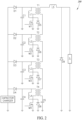
- FIG 2 shows a circuit 200 that is operable to generate a high voltage pulse to drive a TPER reactor 102, for example the TPER reactor 102 illustrated in Figure 1 .
- a series of inductively coupled switching stages 202a, 202b, 202c, 202d (only four shown, collectively 202) discharge capacitors C1, C2, C3, C4 in series to achieve voltage multiplication.
- Operating switches M1, M2, M3, M4 causes energy to flow from these capacitors C1, C2, C3, C4 to energize a drift step recovery diode D9, which rapidly interrupts energy stored by a charge circuit inductor L5 to produce a high power, high voltage electrical pulse, which is transmitted to the anode or anodes of the TPER reactor 102.
- FIG 3 shows a system 300 to treat cooking smoke emissions using a transient pulsed plasma, according to another illustrated implementation.
- the system 300 is similar to the system 100 ( Figure 1 ), and similar or even identical structures are identified in Figure 3 with the same reference numbers as employed in Figure 1 . In the interest of conciseness, only significant differences are discussed below.
- a DC voltage source 302 may also be connected to the TPER reactor 102, in addition to the high voltage nanosecond pulse generator (e.g., power supply) 104.
- the nanosecond duration pulses 120 are coupled onto the anode or anodes of the TPER reactor 102, which is biased to a set DC voltage via the DC voltage source 302. The voltage of the nanosecond duration pulses 120 adds to the DC voltage.
- Figure 4 shows a portion of a system 400 to treat cooking smoke emissions using a transient pulsed plasma, according to one illustrated implementation.
- the nanosecond pulses 120 ( Figs. 1 and 3 ) are capacitively coupled onto the anode or anodes 102a ( Figs. 1 and 3 ) of the TPER reactor 102 through a DC coupling capacitor C 1 .
- a low pass filter (illustrated enclosed in broken-line box) 402 is used to isolate the DC supply (e.g., DC voltage source 302) from the high voltage, nanosecond duration pulse generator 104.
- the system shows one implementation of how a DC voltage source 302 and a high voltage, nanosecond duration pulse generator (e.g., power supply) 104 may be connected to a TPER reactor 102. Both the DC voltage source 302 and the high voltage, nanosecond duration pulse generator 104 are electrically coupled to the anode or anodes of the TPER reactor 102.
- the DC voltage source 302 is electrically isolated from the high voltage, nanosecond pulse generator 104 by a low pass filter, comprised of inductor L 1 , resistor R 2 , and capacitor C 2 .
- the high voltage, nanosecond pulse generator 104 is electrically isolated from the DC voltage source 302 by a coupling capacitor C 1 .
- a resistor R 1 provides a DC path to allow the DC voltage source 302 to fully charge the coupling capacitor C 1 .
- the values of coupling capacitor C 1 , inductor L 1 , and capacitor C 2 are determined by the desired or defined pulse parameters of the high voltage, nanosecond pulse generator 104.
- Capacitor C 1 and capacitor C 2 are chosen to provide low impedance to the nanosecond duration pulse; whereas, inductor L 1 is chosen to appear as a high impedance.
- the value of resistor R 1 is chosen to be sufficiently large so as to avoid excessive heating when the high voltage nanosecond pulse generator 104 is running at maximum or rated power.
- Resistor R 2 is chosen to sufficiently damp the resonance of inductor L 1 , coupling capacitor C 1 , and capacitor C 2 .
- a proof-of-principle experiment of this method and system has been performed in which a TPER reactor based system was tested in a test kitchen facility.
- Two TREP reactors were installed in parallel to a kitchen ventilation system including a charbroiler, hood, duct, and blower. Only a fraction of the full flow was passed through the TPER reactors.
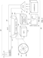
- FIG. 5 shows a system 500 used to perform the experiment referred to immediately above.
- the system 500 is similar to the system 100 ( Figure 1 ), and similar or even identical structures are identified in Figure 5 with the same reference numbers as employed in Figure 1 . In the interest of conciseness, only significant differences are discussed below.
- the system 500 includes a main duct 502 and a tap duct 504.
- the tap duct 504 is used to tap or exhaust a slip stream of the smoke exhaust 506 from the main duct 502 and treated the slip stream of the smoke exhaust 506 by a pair of TPER reactors 508.
- the TPER reactors 508 comprise two 3" diameter TPER reactors, each 3 feet in length, and arranged in parallel with one another.
- Each TPER reactor 508 was powered by a nanosecond pulse generator 104, in particular a TPS Model 201 nanosecond pulse generator.
- the system 500 includes a spectrometer 510.
- the treated smoke exhaust 512 returns to the main duct 502 after being subjected to the non-equilibrated transient plasma.
- SMPS Scanning Mobility Particle Sizer
- TTI Model 3776 Scanning Mobility Particle Sizer
- Hamburgers (75% lean, 25% fat) were cooked for 4.5 minutes per side continuously for 3 hours during this study, as shown in Figure 3 .
- 15 patties were cooked at a time on a grill that was 25 ⁇ 30" in area.
- a total of 375 patties were cooked during this study.
- the cooking emissions (e.g., smoke) 109 collected by the hood 112 was then treated with the TPER reactors.
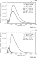
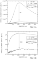
- Figure 6A is a graph 600a that shows the particle number densities measured with and without the plasma treatment via the experimental system 500 ( Figure 5 ) described above at a reactor flow condition of 2.5m/s.
- Figure 6B is a graph 600b that shows the particle number densities measured with and without the plasma treatment via the experimental system 500 ( Figure 5 ) described above for a reactor flow condition of 0.25m/s.
- the integrated peak areas are indicated in Figures 6A and 6B .
- the original untreated particle distributions are peaked around 125-150nm diameter. With plasma treatment, a significant drop in the particle number was observed along with the emergence of a narrow distribution centered around 30-40nm.
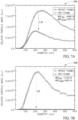
- Figures 7A and 7B are graphs 700a, 700b, respectively, that show the "Relative Particle Mass" in arbitrary units obtained by multiplying the number densities in Figures 3 and 4 , respectively, by the diameter cubed.
- the integrated peak areas are indicated in Figures 7A and 7B .
- 2.4X and 55X-fold reductions in total PM mass were observed for flow rates of 2.5 and 0.25 m/s, respectively.
- Figure 8 is a graph 800 that shows the integrated particle number plotted as a function of pulse repetition rate, which decreases linearly with increasing repetition rate. Here, the total particle number decreases linearly with increasing repetition rate.
- Figure 9A is a graph 900a that shows the particle distributions as a function of voltage dependence.
- Figure 9B is a graph 900b that shows a plot of integrated peak areas ( i . e ., total particle mass) plotted as a function of pulser input voltage for the particle distributions of Figure 9A .
- integrated peak areas i . e ., total particle mass
- a monotonic decrease is observed in the integrated area of the PM peak distribution ( i . e ., total PM mass), with an overall reduction of 40X observed at a pulser input voltage of 400 VDC.
- These input voltages correspond to pulse energies of approximately 10, 20, 40, and 50mJ.
- This plasma-based approach provides a fundamentally different mechanism for breaking down oil-based particulate matter that cannot be achieved with conventional UV and/or ozone approaches, both of which are present in the plasma.
- highly reactive chemical radical species including atomic oxygen, are largely responsible for the effective breakdown of these oil aerosol particles.
- the plasma discharge is produced in a 4" diameter cylindrical reactor (illustrated in Figures 10A and 10B ) with a 5-10 nanosecond high voltage (30 kV) pulse generator together with applied DC bias voltages up to 20 kV.
- the distribution of nanoparticle sizes is centered around 225 nm in diameter, as measured using a scanning mobility particle sizer (SMPS) spectrometer and follows a log-normal distribution.
- SMPS scanning mobility particle sizer
- the plasma-based flow reactor used comprises a 4 foot-long, 4 inch-diameter stainless steel cylindrical anode with a 25mil single-wire cathode arranged in a coaxial geometry, as illustrated in Figures 10A and 10B .
- This plasma-based flow system has electrical feedthroughs on either end of the reactor, one for supplying high DC voltages and the other for high voltage nanosecond pulses, as indicated in Figure 10A .
- AC and DC filters have been built into these feedthroughs in order to protect the nanosecond pulse generator from the high voltage DC bias and vice versa.
- the plasma is produced using a TPS Model 30X pulse generator operating at a peak voltage of 30kV. a pulse repetition rate of 200Hz, and a continuous power of 30W.
- the generation of plasma is assisted by 20kV DC power supply capable of supplying up to 30W of continuous power.
- Baseline particle distributions i.e., histograms
- SMPS scanning mobility particle sizer
- Figure 12A shows particle size distributions taken under an applied DC voltage of 5kV both with and without the nanosecond pulse generator running at a peak voltage of 30kV, pulse repetition rate of 200Hz, and continuous electrical power of 30W. A comparison of these two distributions shows a more than 12-fold reduction of total PM concentration (i.e., 92% remediation).
- the integrated areas are indicated in the plot corresponding to the total particle concentrations both with and without the transient pulsed plasma.
- Figure 12B shows particle size distributions taken with an applied DC voltage of 10kV both with and without a nanosecond pulse generator, exhibiting a more than 1500-fold reduction in PM concentration (i.e., 99.9% remediation). It should be noted that the particle distributions taken with 5kVDC and 10kVDC only, without the nanosecond pulse generator, are nearly identical to the untreated baseline data (i.e., no remediation) plotted in Figure 11 .
- soybean oil rather than PAO-4.
- the soybean oil more closely resembles the oil-based nanoparticles that are generated by the charbroiling of hamburger meat and is often used as a surrogate grease generator following the UL 1046 standard method.
- these soybean oil grease aerosol particles are generated at room temperature and do not contain any carbonaceous particles, such as those produced in the combustion of natural gas.
- Figure 13A shows particle size distributions taken with an applied DC voltage of 2.5kV both with and without the nanosecond pulsed plasma.
- Figure 13B shows particle size distributions taken with an applied DC voltage of 5kV both with and without the nanosecond pulsed plasma.
- logic or information can be stored on any nontransitory computer-readable medium for use by or in connection with any computer and/or processor related system or method.
- a memory is a computer-readable medium that is an electronic, magnetic, optical, or other another physical device or means that contains or stores a computer and/or processor program.
- Logic and/or the information can be embodied in any computer-readable medium for use by or in connection with an instruction execution system, apparatus, or device, such as a computer-based system, processor-containing system, or other system that can fetch the instructions from the instruction execution system, apparatus, or device and execute the instructions associated with logic and/or information.
- a "computer-readable medium” can be any means that can store, communicate, propagate, or transport the program associated with logic and/or information for use by or in connection with the instruction execution system, apparatus, and/or device.
- the computer-readable medium can be, for example, but not limited to, an electronic, magnetic, optical, electromagnetic, infrared, or semiconductor system, apparatus, device, or propagation medium.
- the computer-readable medium could even be paper or another suitable medium upon which the program associated with logic and/or information is printed, as the program can be electronically captured, via for instance optical scanning of the paper or other medium, then compiled, interpreted or otherwise processed in a suitable manner if necessary, and then stored in memory.
- nontransitory signal bearing media include, but are not limited to, the following: recordable type media such as floppy disks, hard disk drives, CD ROMs, digital tape, and computer memory.
Landscapes
- Engineering & Computer Science (AREA)
- Chemical & Material Sciences (AREA)
- Combustion & Propulsion (AREA)
- General Engineering & Computer Science (AREA)
- Mechanical Engineering (AREA)
- General Chemical & Material Sciences (AREA)
- Chemical Kinetics & Catalysis (AREA)
- Oil, Petroleum & Natural Gas (AREA)
- Analytical Chemistry (AREA)
- Health & Medical Sciences (AREA)
- Biomedical Technology (AREA)
- Environmental & Geological Engineering (AREA)
- Physical Or Chemical Processes And Apparatus (AREA)
Description
- This description relates to systems and methods that employ high voltage, high power nanosecond pulses in treating cooking smoke.
- Smoke emissions from chain-driven (i.e., conveyor-belt) charbroilers has been regulated by the air quality management district (SC-AQMD) in southern California since 1997 (see RULE 1138). This "smoke" consists of oil particles (particulate matter) typically around 150nm in diameter. This problem has been "solved" using high temperature catalysts that cost $1500-$2000, are stable for more than 10 years, and are nearly maintenance-free. These catalyst-based systems make use of the high temperatures within a few inches of the cooking surface. However, these relatively large chain-driven charbroilers are only found in large fast food restaurants and comprise a relatively small fraction of total restaurant smoke emissions.
- Open-underfire broilers (the kind most people are familiar with) are found in thousands of restaurants in the southern California area alone. These emissions are currently not regulated but account for 85% of all restaurant emissions in the South Coast region of California. Typical mass flow rates for these charbroilers are around 10 lbs/day or volumetric flow rates of 1600 ft3/min and higher. This corresponds to approximately 5 grams of particulate matter (PM) per hamburger. The same high temperature catalysts used for the chain-driven broilers are not applicable here, because the exhaust is cold by the time it reaches the hood approximately 1m away.
CN 201 715 597 U teaches an air sterilization system which has a plasma purification function, an anode and a cathode in a plasma reactor.
WO 2004/049769 A1 discloses an industrial equipment for generation of streamer discharge plasmas, which comprises a power source, a reactor and a chemical physical technological processing system.
WO 2008/055337 A1 discloses a non-thermal plasma and integral catalyst system used to neutralize organic particulate emissions released into the environment by commercial and/or industrial air streams. - The present disclosure is directed toward a system and method to remove and reduce particular matter from commercial charbroiling processes. This is achieved by means of treating the smoke produced by the charbroiling process as it flows through the exhaust system and into a Transient Plasma Emission Remediation (TPER) Reactor, where it is treated with a non-equilibrated transient plasma that is generated by high voltage electrical pulses, each with a duration of nanoseconds.
- In particular, a method and system for treating cooking smoke emissions as defined in the claims that follow is provided. The system substantially reduces particulate matter produced in cooking, for example in commercial charbroiling processes (e.g., cooking / grilling of hamburger meat). Both a reduction in the size distribution and total particulate mass is advantageously achieved using the methods and systems described herein.
- The system includes a DC voltage source to supplement the TPER reactor. According to the invention, a DC voltage is connected to a center conductor of a TPER reactor. In this configuration, the high voltage nanosecond pulses are coupled onto the center conductor of the TPER reactor and are superimposed on top of the DC voltage. This may be done either to produce a static electric field that lowers the electric field required to be generated by the high voltage, nanosecond duration pulse that is required to strike a non-equilibrated transient plasma. The DC voltage may also be used to produce a static electric field that behaves like an electrostatic precipitator (ESP) and serves to precipitate particulate matter out of the gas flow.
- In the drawings, identical reference numbers identify similar elements or acts. The sizes and relative positions of elements in the drawings are not necessarily drawn to scale. For example, the shapes of various elements and angles are not drawn to scale, and some of these elements are arbitrarily enlarged and positioned to improve drawing legibility. Further, the particular shapes of the elements as drawn, are not intended to convey any information regarding the actual shape of the particular elements, and have been solely selected for ease of recognition in the drawings.
-
Figure 1 is a schematic diagram showing a system to treat cooking emissions according to at least one illustrated implementation, the system including a kitchen ventilation system including a charbroiler, hood, duct, and blower, and the system also including a Transient Plasma Emission Remediation (TPER) reactor installed in a flow path of the kitchen ventilation system, and a nanosecond pulse generator coupled to drive the TPER reactor. -
Figure 2 is a circuit diagram showing a circuit suitable for inclusion in the a nanosecond pulse generator ofFigure 1 , according to at least one illustrated implementation, the illustrated circuit operable to generate the high voltage, nanosecond duration electrical pulses to generate plasma in the TPER reactor. -
Figure 3 is a schematic diagram showing a system to treat cooking emissions according to at least another illustrated implementation, the system including a kitchen ventilation system including a charbroiler, hood, duct, and blower, and the system also including a Transient Plasma Emission Remediation (TPER) reactor installed in a flow path of the kitchen ventilation system, and a DC bias voltage in addition to a nanosecond pulse generator coupled to drive the TPER reactor. -
Figure 4 is a circuit diagram showing both a DC voltage supply and the high voltage nanosecond supply coupled to drive the TPER reactor ofFigure 3 . -
Figure 5 is a schematic diagram of an experimental setup used to test a TPER reactor and nanosecond pulse generator. -
Figure 6A is a graph that shows plots of a set of particle number densities versus particle size measured (using an SMPS) with and without the plasma treatment for a flow conditions of 2.5m/s. -
Figure 6B is a graph that shows plots of a set of particle number densities versus particle size measured (using an SMPS) with and without the plasma treatment for a flow conditions of 0.25m/s. -
Figure 7A is a graph that shows plots of a relative particle mass measured versus particle size with and without the plasma treatment for a flow condition of 2.5m/s. -
Figure 7B is a graph that shows plots of a relative particle mass versus particle size measured with and without the plasma treatment for a flow condition of 0.25m/s. -
Figure 8 is a graph that shows an integrated particle numbers (i.e., total particle number) plotted as a function of pulse repetition rate. -
Figure 9A is a graph that shows a set of plots of a set of particle number densities for various sized particles measured for various respective pulser input voltages. -
Figure 9B is a graph that shows a plot of integrated peak areas (i.e., total particle mass) plotted as a function of pulser input voltage. -
Figure 10A is an isometric view of a plasma-based reactor for treating restaurant particulate emissions remediation, according to at least one illustrated implementation. -
Figure 10B is a photograph of a plasma discharge at the output port of the reactor system ofFigure 10A . -
Figure 11 is a graph showing plots of a particle size distributions produced using POA-4 oil in an aerosol particle generator, with spectra captured 30 minutes apart using a scanning mobility particle sizer (SMPS). -
Figure 12A is a graph showing a plot of a particle size distribution obtained with PAO-4 under an applied DC voltage of 5kV, both with and without a 30kV nanosecond pulsed plasma (pulse repetition rate of 200Hz and electrically continuous power of 30W). -
Figure 12B is a graph showing a plot of a particle size distribution obtained with PAO-4 under an applied DC voltage 10kV, both with and without a 30kV nanosecond pulsed plasma (pulse repetition rate of 200Hz and electrically continuous power of 30W). -
Figure 13A is a graph showing a particle size distribution obtained with soybean oil under an applied DC voltage of 2.5kV, both with and without the nanosecond pulsed plasma running at a peak voltage of 30kV, pulse repetition rate of 200Hz, and continuous power of 30W. -
Figure 13B is a graph showing a particle size distribution obtained with soybean oil under an applied DC voltage of 5kV, both with and without the nanosecond pulsed plasma running at a peak voltage of 30kV, pulse repetition rate of 2.00Hz, and continuous power of 30W. - Reference throughout this specification to "one embodiment" or "an embodiment" means that a particular feature, structure or characteristic described in connection with the embodiment is included in at least one embodiment. Thus, the appearances of the phrases "in one embodiment" or "in an embodiment" in various places throughout this specification are not necessarily all referring to the same embodiment. Furthermore, the particular features, structures, or characteristics may be combined in any suitable manner in one or more embodiments.
- As used in this specification and the appended claims, the singular forms "a," "an," and "the" include plural referents unless the content clearly dictates otherwise. It should also be noted that the term "or" is generally employed in its sense including "and/or" unless the content clearly dictates otherwise.
-
Figure 1 shows asystem 100 to treat cooking smoke emissions using a transient pulsed plasma, according to one illustrated implementation. - The
system 100 includes a Transient Plasma Emission Remediation (TPER)reactor 102 and ananosecond pulse generator 104 coupled to drive thatTPER reactor 102. TheTPER reactor 102 is designed to connect to anexhaust system 106, for example in series with one ormore ducts exhaust system 106 that vents the cooking emissions (e.g., smoke) 109 generated by a cooking appliance 110 (e.g., charbroiler) out of a building and into the atmosphere. Theexhaust system 106 may include one ormore hoods 112 positioned relatively above thecooking appliance 110 to capture the cooking emissions (e.g., smoke) 109 produced by the cooking process. Thehood 112 can take a variety of forms. Thehood 1 12 will typically comprise a stainless steel sheet metal enclosure with a relative large hood input vent at one end, and a relatively smaller hood output vent at another end. Theexhaust system 106 may include one or more blowers (e.g., fans) 114 positioned to draw and, or push the cooking emissions (e.g., smoke) 109 through the duct(s) 108 from thehood 112 to anexhaust outlet vent 116. Thehood 112 and the ducts 108 define a fluid flow path (represented by arrows )113 to constrain and guide passage of the capture the cooking emissions (e.g., smoke) 109. - In one embodiment, the
TPER reactor 102 for particulate matter remediation is comprised of a stainless steelcylindrical reactor anode 102a with acoaxial electrode 102b. Thiscoaxial TPER reactor 102 comprises a thin wire, between 0.001 inch and 1 inch in diameter that is centered inside of an electrically conductive tube with an inner diameter between 1 inch and 24 inches, where the inner diameter is determined by the maximum voltage of dienanosecond pulse generator 104 that is driving theplasma generating reactor 102. An impedance ofTPER reactor 102 is matched with a source cable 126 in order to reduce voltage reflections. TheTPER reactor 102 provides a corona discharge in a coaxial cell geometry. -
Figure 1 also shows the resulting transient plasma (i.e., high electron energy, low-temperature plasma) 118, as well as the shape of a typicalhigh voltage pulse 120 produced by the nanosecond pulse generator and supplied to theTPER reactor 102. Theplasma 118 is generated inside theTPER reactor 102 by driving a high voltage, nanosecond durationelectrical pulse 120 onto thecenter conductor 102a or conductors of the TPER reactor(s) 102. In some implementations, the nanosecond durationelectrical pulse 120 may have a duration of approximately equal to or less than 100 ns and may have a magnitude of approximately equal to or greater than >1 kV. According to the invention, values for the nanosecond durationelectrical pulse 120 may be a duration in a range of 0.1 ns to 100 ns, inclusive, and a magnitude in a range of 1 kV to 100 kV, inclusive. - In another implementation, a 4-electrode geometry is utilized for the
plasma generating reactor 102, where the diameter of the wire generating the plasma and the outer tube are sized similarly to the ones described for the single wire geometry. - The
system 100 may take the form of a retro-fit system, for example sized and dimensioned or shaped to be installed as part of a previously installed exhaust system that draws smoke from a vicinity of a cooking appliance and venting such into the atmosphere, typically with one or more filters. The retro-fit system may allow for the removal of one or more filters, for example including a replacement section or piece of duct to replace a section in which filters are mounted, or to provide a bypass fluid path around pre-existing filters or pre-existing filter section. In some implementations, one ormore TPER reactors 102 could be installed on a roof of a building, for example connected in series with existing exhaust ducts. -
Figure 2 shows acircuit 200 that is operable to generate a high voltage pulse to drive aTPER reactor 102, for example theTPER reactor 102 illustrated inFigure 1 . A series of inductively coupled switching stages 202a, 202b, 202c, 202d (only four shown, collectively 202) discharge capacitors C1, C2, C3, C4 in series to achieve voltage multiplication. Operating switches M1, M2, M3, M4 causes energy to flow from these capacitors C1, C2, C3, C4 to energize a drift step recovery diode D9, which rapidly interrupts energy stored by a charge circuit inductor L5 to produce a high power, high voltage electrical pulse, which is transmitted to the anode or anodes of theTPER reactor 102. -
Figure 3 shows asystem 300 to treat cooking smoke emissions using a transient pulsed plasma, according to another illustrated implementation. Thesystem 300 is similar to the system 100 (Figure 1 ), and similar or even identical structures are identified inFigure 3 with the same reference numbers as employed inFigure 1 . In the interest of conciseness, only significant differences are discussed below. - In the
system 300, aDC voltage source 302 may also be connected to theTPER reactor 102, in addition to the high voltage nanosecond pulse generator (e.g., power supply) 104. In this implementation, thenanosecond duration pulses 120 are coupled onto the anode or anodes of theTPER reactor 102, which is biased to a set DC voltage via theDC voltage source 302. The voltage of thenanosecond duration pulses 120 adds to the DC voltage. -
Figure 4 shows a portion of asystem 400 to treat cooking smoke emissions using a transient pulsed plasma, according to one illustrated implementation. In this implementation, the nanosecond pulses 120 (Figs. 1 and3 ) are capacitively coupled onto the anode oranodes 102a (Figs. 1 and3 ) of theTPER reactor 102 through a DC coupling capacitor C1. A low pass filter (illustrated enclosed in broken-line box) 402 is used to isolate the DC supply (e.g., DC voltage source 302) from the high voltage, nanosecondduration pulse generator 104. - In particular, the system shows one implementation of how a
DC voltage source 302 and a high voltage, nanosecond duration pulse generator (e.g., power supply) 104 may be connected to aTPER reactor 102. Both theDC voltage source 302 and the high voltage, nanosecondduration pulse generator 104 are electrically coupled to the anode or anodes of theTPER reactor 102. TheDC voltage source 302 is electrically isolated from the high voltage,nanosecond pulse generator 104 by a low pass filter, comprised of inductor L1, resistor R2, and capacitor C2. The high voltage,nanosecond pulse generator 104 is electrically isolated from theDC voltage source 302 by a coupling capacitor C1. A resistor R1 provides a DC path to allow theDC voltage source 302 to fully charge the coupling capacitor C1. The values of coupling capacitor C1, inductor L1, and capacitor C2 are determined by the desired or defined pulse parameters of the high voltage,nanosecond pulse generator 104. Capacitor C1 and capacitor C2 are chosen to provide low impedance to the nanosecond duration pulse; whereas, inductor L1 is chosen to appear as a high impedance. The value of resistor R1 is chosen to be sufficiently large so as to avoid excessive heating when the high voltagenanosecond pulse generator 104 is running at maximum or rated power. Resistor R2 is chosen to sufficiently damp the resonance of inductor L1, coupling capacitor C1, and capacitor C2. - A proof-of-principle experiment of this method and system has been performed in which a TPER reactor based system was tested in a test kitchen facility. Two TREP reactors were installed in parallel to a kitchen ventilation system including a charbroiler, hood, duct, and blower. Only a fraction of the full flow was passed through the TPER reactors.
-
Figure 5 shows asystem 500 used to perform the experiment referred to immediately above. Thesystem 500 is similar to the system 100 (Figure 1 ), and similar or even identical structures are identified inFigure 5 with the same reference numbers as employed inFigure 1 . In the interest of conciseness, only significant differences are discussed below. - In contrast to the system 100 (
Figure 1 ), thesystem 500 includes amain duct 502 and atap duct 504. Thetap duct 504 is used to tap or exhaust a slip stream of thesmoke exhaust 506 from themain duct 502 and treated the slip stream of thesmoke exhaust 506 by a pair ofTPER reactors 508. TheTPER reactors 508 comprise two 3" diameter TPER reactors, each 3 feet in length, and arranged in parallel with one another. EachTPER reactor 508 was powered by ananosecond pulse generator 104, in particular a TPS Model 201 nanosecond pulse generator. Thesystem 500 includes aspectrometer 510. The treatedsmoke exhaust 512 returns to themain duct 502 after being subjected to the non-equilibrated transient plasma. - In particular, particle distributions were collected using a Scanning Mobility Particle Sizer (SMPS) spectrometer (TSI Model 3776) over the range from 14-650nm. Hamburgers (75% lean, 25% fat) were cooked for 4.5 minutes per side continuously for 3 hours during this study, as shown in
Figure 3 . 15 patties were cooked at a time on a grill that was 25×30" in area. A total of 375 patties were cooked during this study. The cooking emissions (e.g., smoke) 109 collected by thehood 112 was then treated with the TPER reactors. -
Figure 6A is agraph 600a that shows the particle number densities measured with and without the plasma treatment via the experimental system 500 (Figure 5 ) described above at a reactor flow condition of 2.5m/s.Figure 6B is agraph 600b that shows the particle number densities measured with and without the plasma treatment via the experimental system 500 (Figure 5 ) described above for a reactor flow condition of 0.25m/s. The integrated peak areas are indicated inFigures 6A and 6B . For these datasets, the original untreated particle distributions are peaked around 125-150nm diameter. With plasma treatment, a significant drop in the particle number was observed along with the emergence of a narrow distribution centered around 30-40nm. The integrated area of the dominant peak shows a factor of 1.7X reduction in PM number density (i.e., 4.62/2.71=1.7X) at high flow rates (2.5m/s) and a 10-fold reduction in PM at low flow rates (0.25m/s). - Since smaller diameter nanoparticles have substantially lower mass than larger diameter nanoparticles, it may be more appropriate to plot the particle mass instead of number density.
Figures 7A and 7B aregraphs Figures 3 and4 , respectively, by the diameter cubed. The integrated peak areas are indicated inFigures 7A and 7B . Here, 2.4X and 55X-fold reductions in total PM mass were observed for flow rates of 2.5 and 0.25 m/s, respectively. - The particle distributions were also measured as a function of the pulse repetition rate.
Figure 8 is agraph 800 that shows the integrated particle number plotted as a function of pulse repetition rate, which decreases linearly with increasing repetition rate. Here, the total particle number decreases linearly with increasing repetition rate. These results demonstrate the scalability of this approach for treating higher flow rates and larger systems at higher repetition rates. -
Figure 9A is agraph 900a that shows the particle distributions as a function of voltage dependence.Figure 9B is a graph 900b that shows a plot of integrated peak areas (i.e., total particle mass) plotted as a function of pulser input voltage for the particle distributions ofFigure 9A . Here, again, a monotonic decrease is observed in the integrated area of the PM peak distribution (i.e., total PM mass), with an overall reduction of 40X observed at a pulser input voltage of 400 VDC. These input voltages correspond to pulse energies of approximately 10, 20, 40, and 50mJ. These results demonstrate the scalability of this approach for treating higher flow rates and larger systems with higher pulse powers. - These measurements demonstrate the effectiveness of transient pulsed plasmas to provide substantial remediation of particulate matter (PM) produced by commercial charbroiling processes (e.g., cooking of hamburger meat). The scalability of this approach for treating higher flow rates and larger systems is also demonstrated as a function of both pulse repetition rate and pulse energy.
- This plasma-based approach provides a fundamentally different mechanism for breaking down oil-based particulate matter that cannot be achieved with conventional UV and/or ozone approaches, both of which are present in the plasma. Here, highly reactive chemical radical species, including atomic oxygen, are largely responsible for the effective breakdown of these oil aerosol particles.
- One possible advantage of this plasma-based approach lies in the substantially improved flow through the system, which reduces the power requirements associated with the fan or blower. Typically, with filter-based approaches, 2-3 filters are configured in series, resulting in a considerable pressure drop which, in turn, requires high power blowers to be utilized in order to achieve the necessary flow rates for kitchen ventilation compliance. Since there is essential no pressure drop across the plasma-based reactor, significantly lower blower powers can be used to achieve the same flow rates, enabling the overall system (including the nanosecond pulse generator) to consume less power than current filter-based systems.
- Other features of the disclosed embodiments will become apparent from the following detailed description, taken in conjunction with the accompanying drawings, which illustrate, by way of example, the principles of the disclosed embodiments.
- Another proof-of-principle experiment of the method by which a DC bias is applied together with the nanosecond pulse is shown in
Figures 10A, 10B ,11 ,12A, 12B ,13A and 13B . Here, both polyaromatic olefin PAO-4 and soybean oil particulates created by an oil aerosol generator are treated. As illustrated by the data, a more than three-order-of-magnitude reduction in particulates (i.e., 99.9% remediation) can be achieved with the treatment system described herein. In these tests, the plasma discharge is produced in a 4" diameter cylindrical reactor (illustrated inFigures 10A and 10B ) with a 5-10 nanosecond high voltage (30 kV) pulse generator together with applied DC bias voltages up to 20 kV. The distribution of nanoparticle sizes is centered around 225 nm in diameter, as measured using a scanning mobility particle sizer (SMPS) spectrometer and follows a log-normal distribution. - In this experiment, an oil aerosol generator from Aerosol Technologies International (ATI, Inc.) was employed, which creates an oil aerosol by forcing compressed air through a Laskin nozzle. The plasma-based flow reactor used comprises a 4 foot-long, 4 inch-diameter stainless steel cylindrical anode with a 25mil single-wire cathode arranged in a coaxial geometry, as illustrated in
Figures 10A and 10B . This plasma-based flow system has electrical feedthroughs on either end of the reactor, one for supplying high DC voltages and the other for high voltage nanosecond pulses, as indicated inFigure 10A . AC and DC filters have been built into these feedthroughs in order to protect the nanosecond pulse generator from the high voltage DC bias and vice versa. The plasma is produced using a TPS Model 30X pulse generator operating at a peak voltage of 30kV. a pulse repetition rate of 200Hz, and a continuous power of 30W. Here, the generation of plasma is assisted by 20kV DC power supply capable of supplying up to 30W of continuous power. Baseline particle distributions (i.e., histograms) were measured using a scanning mobility particle sizer (SMPS) without a plasma or DC bias and exhibit highly stable distributions, as show inFigure 11 . -
Figure 12A shows particle size distributions taken under an applied DC voltage of 5kV both with and without the nanosecond pulse generator running at a peak voltage of 30kV, pulse repetition rate of 200Hz, and continuous electrical power of 30W. A comparison of these two distributions shows a more than 12-fold reduction of total PM concentration (i.e., 92% remediation). Here, the integrated areas are indicated in the plot corresponding to the total particle concentrations both with and without the transient pulsed plasma. Similarly,Figure 12B shows particle size distributions taken with an applied DC voltage of 10kV both with and without a nanosecond pulse generator, exhibiting a more than 1500-fold reduction in PM concentration (i.e., 99.9% remediation). It should be noted that the particle distributions taken with 5kVDC and 10kVDC only, without the nanosecond pulse generator, are nearly identical to the untreated baseline data (i.e., no remediation) plotted inFigure 11 . - A separate set of measurements was taken using soybean oil rather than PAO-4. The soybean oil more closely resembles the oil-based nanoparticles that are generated by the charbroiling of hamburger meat and is often used as a surrogate grease generator following the UL 1046 standard method. However, it is also worth noting that these soybean oil grease aerosol particles are generated at room temperature and do not contain any carbonaceous particles, such as those produced in the combustion of natural gas.
Figure 13A shows particle size distributions taken with an applied DC voltage of 2.5kV both with and without the nanosecond pulsed plasma.Figure 13B shows particle size distributions taken with an applied DC voltage of 5kV both with and without the nanosecond pulsed plasma. For a DC bias of 2.5kV, a 21-fold reduction in PM concentration (i.e., 96% remediation) was observed. For a DC bias of SkVDC, a more than 1260-fold reduction in PM concentration (i.e., 99.9% remediation) was observed. Without being bound by theory, the improved remediation obtained with a DC bias of 5kV compared to that of 2.5kVDC can be attributed to the increased electric fields that are achieved when adding the 30kV peak pulse voltage. At higher DC biases, the plasma density is higher and fills a more substantial volume of the reactor. It should, again, be noted that the distributions observed with 2.5 and 5kVDC bias only (i.e., without the nanosecond pulse generator) are nearly identical to the untreated data (i.e., no remediation). - Various embodiments of the devices and/or processes via the use of block diagrams, schematics, and examples have been set forth herein. Insofar as such block diagrams, schematics, and examples contain one or more functions and/or operations, it will be understood by those skilled in the art that each function and/or operation within such block diagrams, flowcharts, or examples can be implemented, individually and/or collectively, by a wide range of hardware, software, firmware, or virtually any combination thereof. In one implementation, the present subject matter may be implemented via Application Specific Integrated Circuits (ASICs). However, those skilled in the art will recognize that the embodiments disclosed herein, in whole or in part, can be equivalently implemented in standard integrated circuits, as one or more computer programs running on one or more computers (e.g., as one or more programs running on one or more computer systems), as one or more programs running on one or more controllers (e.g., microcontrollers) as one or more programs running on one or more processors (e.g., microprocessors), as firmware, or as virtually any combination thereof, and that designing the circuitry and/or writing the code for the software and or firmware would be well within the skill of one of ordinary skill in the art in light of this disclosure.
- When logic is implemented as software and stored in memory, one skilled in the art will appreciate that logic or information, can be stored on any nontransitory computer-readable medium for use by or in connection with any computer and/or processor related system or method. In the context of this document, a memory is a computer-readable medium that is an electronic, magnetic, optical, or other another physical device or means that contains or stores a computer and/or processor program. Logic and/or the information can be embodied in any computer-readable medium for use by or in connection with an instruction execution system, apparatus, or device, such as a computer-based system, processor-containing system, or other system that can fetch the instructions from the instruction execution system, apparatus, or device and execute the instructions associated with logic and/or information. In the context of this specification, a "computer-readable medium" can be any means that can store, communicate, propagate, or transport the program associated with logic and/or information for use by or in connection with the instruction execution system, apparatus, and/or device. The computer-readable medium can be, for example, but not limited to, an electronic, magnetic, optical, electromagnetic, infrared, or semiconductor system, apparatus, device, or propagation medium. More specific examples (a non-exhaustive list) of the computer-readable medium would include the following: an electrical connection having one or more wires, a portable computer diskette (magnetic, compact flash card, secure digital, or the like), a random access memory (RAM), a read-only memory (ROM), an erasable programmable read-only memory (EPROM, EEPROM, or Flash memory), an optical fiber, and a portable compact disc read-only memory (CDROM). Note that the computer-readable medium, could even be paper or another suitable medium upon which the program associated with logic and/or information is printed, as the program can be electronically captured, via for instance optical scanning of the paper or other medium, then compiled, interpreted or otherwise processed in a suitable manner if necessary, and then stored in memory.
- In addition, those skilled in the art will appreciate that certain mechanisms of taught herein are capable of being distributed as a program product in a variety of forms, and that an illustrative embodiment applies equally regardless of the particular type of nontransitory signal bearing media used to actually carry out the distribution. Examples of nontransitory signal bearing media include, but are not limited to, the following: recordable type media such as floppy disks, hard disk drives, CD ROMs, digital tape, and computer memory.
Claims (15)
- A method to remove and reduce particulate matter from cooking exhaust streams, the method comprising:capturing a cooking exhaust stream (109) via a hood (112);passing the captured cooking exhaust stream through a transient plasma emission remediation, TPER, reactor (102);applying a DC bias voltage by a DC voltage source (302) to an energized conductor (102) of the TPER reactor, the energized conductor (102) being a center conductor of the TPER reactor; anddriving the TPER reactor with a high voltage pulse (120) with a duration of nanoseconds to generate a non-equilibrated transient plasma (118) in a portion of the TPER reactor through which the captured cooking exhaust stream passes, wherein the high voltage, nanosecond duration pulse is coupled onto the DC biased conductor of the TPER reactor;characterized in thatthe high voltage, nanosecond duration pulse is coupled onto the center conductor of the TPER reactor and is superimposed on top of the DC bias voltage;and wherein the high voltage pulse (120) has a magnitude in a range of 1 kV to 100 kV, inclusive and a duration in a range of 0.1 nanosecond to 100 nanoseconds, inclusive.
- The method of claim 1 wherein the hood is positioned over a cooking appliance and capturing a cooking exhaust stream via a hood includes capturing smoke generated by cooking of food by the cooking appliance.
- The method of claim 1 wherein the cooking appliance is a charbroiler (110), the hood is positioned over the charbroiler, and capturing a cooking exhaust stream via a hood includes capturing smoke generated by charbroiling of meat by the charbroiler.
- The method of any of claims 1 through 3 wherein driving the TPER reactor with a high voltage pulse with a duration of nanoseconds includes applying a fast rising, high voltage pulse with a duration of nanoseconds to at least one electrode (102a, 102b) of the TPER reactor.
- The method of any of claims 1 through 3 wherein passing the captured cooking exhaust stream through a TPER reactor includes passing the captured cooking exhaust stream through a TPER reactor that is coupled serially in a fluid flow path (113) between the hood and an exhaust outlet vent (116).
- The method of any of claims 1 through 3 wherein passing the captured cooking exhaust stream through a TPER reactor includes operating at least one blower (114) that is coupled to a fluid flow path to move the captured cooking exhaust stream from the hood toward an exhaust outlet vent.
- The method of claim 1 wherein driving the TPER reactor with a high voltage pulse with a duration of nanoseconds includes applying an electric field of the high voltage pulse with the nanosecond duration on top of a static electric field produced by the DC bias voltage, wherein the high voltage pulse with the nanosecond duration is coupled onto the DC biased conductor of the TPER reactor through a coupling capacitor, and the DC high voltage source (302) is isolated from a high voltage pulse with a nanosecond duration source by means of a low pass filter (402).
- The method of claim 1 wherein applying a DC bias voltage by a DC voltage source to an energized conductor of the TPER reactor includes applying a DC bias that produces a static electric field that does not produce an electrical discharge.
- The method of claim 1 wherein applying a DC bias voltage by a DC voltage source to an energized conductor of the TPER reactor includes applying a DC bias that lowers a field generated by the high voltage pulse with the nanosecond duration that is required to strike a non-equilibrated transient plasma.
- The method of claim 1 wherein applying a DC bias voltage by a DC voltage source to an energized conductor of the TPER reactor includes applying a DC bias voltage that produces a static electric field that precipitates particulate matter out of the gas flow.
- A system (100) to remove and reduce particulate matter from cooking exhaust streams, the system comprising:at least one a transient plasma emission remediation, TPER, reactor (102), the at least one a TPER reactor including an electrically conductive tube that forms a first electrode and at least a second electrode position in an interior of the electrically conductive tube, the electrically conductive tube sized to be serially coupled in a flow path formed by one or more ducts (108a, 108b, 108c);a DC high voltage source (302) electrically coupled to apply a DC bias voltage to at least one conductor (102) of the at least one TPER reactor, the at least one conductor (102) being a center conductor of the at least one TPER reactor; andat least one nanosecond pulse generator (104) coupled to drive the at least one TPER reactor, wherein the high voltage, nanosecond duration pulse is coupled onto a DC biased conductor of the TPER reactor;characterized in thatthe high voltage, nanosecond duration pulse is coupled onto the center conductor of the TPER reactor and is superimposed on top of the DC bias voltage;wherein the high voltage nanosecond duration pulse (120) has a magnitude in a range of 1 kV to 100 kV, inclusive and has a duration in a range of 0.1 nanosecond to 100 nanoseconds, inclusive.
- The system of claim 11, further comprising:a hood positioned with respect to at least one cooking appliance to capture a cooking exhaust stream, wherein the cooking appliance is a charbroiler, the cooking exhaust stream is smoke created by cooking of meat by the charbroiler, and the hood is positioned above the charbroiler to capture the smoke created by cooking of meat by the charbroiler;one or more ducts that provide a fluid path been the hood and an exhaust outlet vent, wherein the at least one TPER reactor is positioned in the fluid path between the hood and the exhaust outlet vent.
- The system of claim 11 wherein the at least one TPER reactor is coaxial, comprising an electrically conductive tube and a center conductor that is centered inside of the electrically conductive tube.
- The system of any of claims 11 through 13 wherein the at least one nanosecond pulse generator coupled to drive the at least one TPER reactor is operable to supply a fast rising, high voltage pulse with a duration of nanoseconds to produce a non-equilibrated transient plasma inside at least a portion of the at least one TPER reactor.
- The system of claim 11, further comprising:a coupling capacitor through which a high voltage, nanosecond duration pulse is coupled onto the at least one conductor to which the DC bias voltage is applied; anda low pass filter (402) that isolates the DC high voltage source from the at least one nanosecond pulse generator that generates high voltage, nanosecond duration.
Applications Claiming Priority (2)
| Application Number | Priority Date | Filing Date | Title |
|---|---|---|---|
| US201862699475P | 2018-07-17 | 2018-07-17 | |
| PCT/US2019/041228 WO2020018327A1 (en) | 2018-07-17 | 2019-07-10 | Method and system for treating cooking smoke emissions using a transient pulsed plasma |
Publications (4)
| Publication Number | Publication Date |
|---|---|
| EP3824223A1 EP3824223A1 (en) | 2021-05-26 |
| EP3824223A4 EP3824223A4 (en) | 2021-08-18 |
| EP3824223C0 EP3824223C0 (en) | 2024-03-06 |
| EP3824223B1 true EP3824223B1 (en) | 2024-03-06 |
Family
ID=69161428
Family Applications (1)
| Application Number | Title | Priority Date | Filing Date |
|---|---|---|---|
| EP19838770.6A Active EP3824223B1 (en) | 2018-07-17 | 2019-07-10 | Method and system for treating cooking smoke emissions using a transient pulsed plasma |
Country Status (3)
| Country | Link |
|---|---|
| US (1) | US11478746B2 (en) |
| EP (1) | EP3824223B1 (en) |
| WO (1) | WO2020018327A1 (en) |
Families Citing this family (2)
| Publication number | Priority date | Publication date | Assignee | Title |
|---|---|---|---|---|
| US11629860B2 (en) | 2018-07-17 | 2023-04-18 | Transient Plasma Systems, Inc. | Method and system for treating emissions using a transient pulsed plasma |
| US11696388B2 (en) * | 2019-05-07 | 2023-07-04 | Transient Plasma Systems, Inc. | Pulsed non-thermal atmospheric pressure plasma processing system |
Family Cites Families (64)
| Publication number | Priority date | Publication date | Assignee | Title |
|---|---|---|---|---|
| US3660685A (en) | 1971-02-25 | 1972-05-02 | Pioneer Magnetics Inc | Pulse generating transformer circuit |
| US3832568A (en) | 1973-08-10 | 1974-08-27 | Sperry Rand Corp | Circuit for generating a single high voltage subnanosecond pulse from a step recovery diode |
| JPS57198372U (en) | 1981-06-12 | 1982-12-16 | ||
| US4677960A (en) | 1984-12-31 | 1987-07-07 | Combustion Electromagnetics, Inc. | High efficiency voltage doubling ignition coil for CD system producing pulsed plasma type ignition |
| JPH02259277A (en) | 1989-03-31 | 1990-10-22 | Isuzu Motors Ltd | Engine starter device |
| KR950010380B1 (en) | 1993-07-27 | 1995-09-16 | 엘지전자주식회사 | Deodorizing apparatus and method with using plazma for an electronic range |
| US5563780A (en) | 1993-12-08 | 1996-10-08 | International Power Systems, Inc. | Power conversion array applying small sequentially switched converters in parallel |
| US6235249B1 (en) * | 1997-04-01 | 2001-05-22 | Engelhard Corporation | Rotary oxidizer systems for control of restaurant emissions |
| JP2002533868A (en) | 1997-10-14 | 2002-10-08 | アドバンスト・エナジー・インダストリーズ・インコーポレイテッド | System for plasma ignition with fast voltage increase |
| US6426666B1 (en) | 1999-11-10 | 2002-07-30 | Virginia Tech Intellectual Properties, Inc. | Diode-assisted gate turn-off thyristor |
| US6474060B2 (en) | 1999-11-17 | 2002-11-05 | Southwest Research Institute | Exhaust gas recirculation filtration system |
| US6831377B2 (en) | 2000-05-03 | 2004-12-14 | University Of Southern California | Repetitive power pulse generator with fast rising pulse |
| US6317341B1 (en) | 2000-11-09 | 2001-11-13 | Simon Fraidlin | Switching circuit, method of operation thereof and single stage power factor corrector employing the same |
| US6779517B2 (en) | 2001-11-29 | 2004-08-24 | Ngk Spark Plug Co., Ltd. | Ignition device for internal combustion engine |
| US20030170898A1 (en) | 2001-12-04 | 2003-09-11 | Gundersen Martin A. | Method for intracellular modifications within living cells using pulsed electric fields |
| CN1266988C (en) | 2002-11-26 | 2006-07-26 | 广东杰特科技发展有限公司 | Industrial apparatus for plasma capable of generating random streamer discharge and application thereof |
| US6906280B2 (en) | 2003-03-21 | 2005-06-14 | The Regents Of The University Of California | Fast pulse nonthermal plasma reactor |
| JP2005235448A (en) | 2004-02-17 | 2005-09-02 | Pearl Kogyo Co Ltd | Plasma processing method and apparatus |
| JP4803965B2 (en) | 2004-03-18 | 2011-10-26 | 日本碍子株式会社 | Junction gate type static induction thyristor and high voltage pulse generator using the junction gate type static induction thyristor |
| SE527259C2 (en) | 2004-06-22 | 2006-01-31 | Mecel Ab | Method and apparatus for controlling the current in a spark plug |
| JP4113170B2 (en) | 2004-09-08 | 2008-07-09 | 株式会社東芝 | Semiconductor device |
| US7767433B2 (en) | 2005-04-22 | 2010-08-03 | University Of Southern California | High voltage nanosecond pulse generator using fast recovery diodes for cell electro-manipulation |
| US7648499B2 (en) | 2006-03-21 | 2010-01-19 | Covidien Ag | System and method for generating radio frequency energy |
| US8922102B2 (en) | 2006-05-12 | 2014-12-30 | Enerpulse, Inc. | Composite spark plug |
| EP2083934A4 (en) * | 2006-11-08 | 2011-02-02 | Air Phaser Environmental Ltd | Apparatus and method for destroying organic compounds in commercial and industrial large volume air emissions |
| KR100872682B1 (en) | 2007-02-02 | 2008-12-10 | 강방권 | Apparatus for uniformly generating atmospheric pressure plasma |
| WO2008118393A1 (en) | 2007-03-23 | 2008-10-02 | University Of Southern California | Compact subnanosecond high voltage pulse generation system for cell electro-manipulation |
| US8066520B2 (en) | 2007-05-01 | 2011-11-29 | Honda Motor Co., Ltd. | Spark plug terminal connection apparatuses and methods |
| US8226901B2 (en) | 2007-07-12 | 2012-07-24 | Imagineering, Inc. | Ignition or plasma generation apparatus |
| US7817396B2 (en) | 2007-10-25 | 2010-10-19 | General Electric Company | High efficiency and high bandwidth plasma generator system for flow control and noise reduction |
| JP5119879B2 (en) | 2007-11-16 | 2013-01-16 | 日産自動車株式会社 | Non-equilibrium plasma discharge control device and non-equilibrium plasma discharge control method for internal combustion engine |
| JP5228450B2 (en) | 2007-11-16 | 2013-07-03 | 日産自動車株式会社 | Operation control device and operation control method for internal combustion engine |
| US8212541B2 (en) | 2008-05-08 | 2012-07-03 | Massachusetts Institute Of Technology | Power converter with capacitive energy transfer and fast dynamic response |
| EP2294693B1 (en) | 2008-05-23 | 2018-08-08 | University of Southern California | Nanosecond pulse generator |
| WO2010009760A1 (en) | 2008-07-22 | 2010-01-28 | Aps Electronic Ag | Multiphase soft-switched dc-dc converter |
| KR100986183B1 (en) | 2008-08-21 | 2010-10-07 | 엘지이노텍 주식회사 | DC / DC converter |
| US8854019B1 (en) | 2008-09-25 | 2014-10-07 | Rf Micro Devices, Inc. | Hybrid DC/DC power converter with charge-pump and buck converter |
| US8329055B2 (en) | 2008-10-02 | 2012-12-11 | Varian Semiconductor Equipment Associates, Inc. | Plasma uniformity control using biased array |
| KR101486585B1 (en) * | 2008-10-28 | 2015-01-26 | 엘지전자 주식회사 | Cooker and method for controlling the same |
| EP2223704A1 (en) | 2009-02-17 | 2010-09-01 | Max-Planck-Gesellschaft zur Förderung der Wissenschaften e.V. | Treating device for treating a body part of a patient with a non-thermal plasma |
| JP2011034953A (en) | 2009-02-26 | 2011-02-17 | Ngk Insulators Ltd | Plasma igniter, and ignition device of internal combustion engine |
| JP2011072076A (en) | 2009-09-24 | 2011-04-07 | Sanken Electric Co Ltd | Dc conversion device |
| CN201715597U (en) | 2009-12-31 | 2011-01-19 | 周云正 | Range hood with plasma purification function |
| US20110267113A1 (en) | 2010-04-28 | 2011-11-03 | International Business Machines Corporation | Frequency multiplier |
| JP5691662B2 (en) | 2011-03-07 | 2015-04-01 | 株式会社デンソー | Non-thermal equilibrium plasma ignition device |
| WO2013096956A1 (en) | 2011-12-23 | 2013-06-27 | University Of Florida Research Foundation, Inc. | Method and apparatus for providing power |
| CN202524634U (en) | 2012-01-10 | 2012-11-07 | 中国科学院西安光学精密机械研究所 | Dielectric Barrier Discharge Enhanced Low Temperature Plasma Brush Generator |
| US10090772B2 (en) | 2012-03-08 | 2018-10-02 | Massachusetts Institute Of Technology | Resonant power converters using impedance control networks and related techniques |
| US8938902B2 (en) | 2012-06-05 | 2015-01-27 | Steven Craig Atwood | System and method for connecting advertising to footwear |
| US20140109886A1 (en) | 2012-10-22 | 2014-04-24 | Transient Plasma Systems, Inc. | Pulsed power systems and methods |
| CN104756385B (en) | 2012-10-31 | 2018-07-06 | 麻省理工学院 | For the system and method for variable frequency multiplier power converter |
| WO2014130697A1 (en) | 2013-02-20 | 2014-08-28 | University Of Southern California | Transient plasma electrode for radical generation |
| US9617965B2 (en) | 2013-12-16 | 2017-04-11 | Transient Plasma Systems, Inc. | Repetitive ignition system for enhanced combustion |
| US10128745B2 (en) | 2014-03-14 | 2018-11-13 | Psemi Corporation | Charge balanced charge pump control |
| KR101846046B1 (en) * | 2014-04-03 | 2018-04-06 | 건국대학교 산학협력단 | Using a heat source of grilled dust removal system |
| US9970407B2 (en) | 2014-09-08 | 2018-05-15 | GM Global Technology Operations LLC | Method and apparatus for controlling operation of an internal combustion engine |
| WO2016101058A1 (en) | 2014-12-23 | 2016-06-30 | The Governing Council Of The University Of Toronto | Flyback converter |
| CN105207256B (en) | 2015-09-16 | 2019-02-22 | 国网智能电网研究院 | A photovoltaic micro-inverter |
| CN105673139A (en) * | 2016-03-21 | 2016-06-15 | 东北电力大学 | Automobile exhaust treatment device and method based on dielectric barrier discharge plasma |
| CN108779754A (en) | 2016-03-31 | 2018-11-09 | 通用汽车环球科技运作有限责任公司 | Internal combustion engine and method of igniting fuel |
| US9831776B1 (en) | 2016-06-16 | 2017-11-28 | Google Inc. | DC-DC converter |
| JP6521187B2 (en) | 2016-10-06 | 2019-05-29 | 株式会社村田製作所 | DC-DC converter |
| WO2019143992A1 (en) | 2018-01-22 | 2019-07-25 | Transient Plasma Systems, Inc. | Inductively coupled pulsed rf voltage multiplier |
| WO2019144037A1 (en) | 2018-01-22 | 2019-07-25 | Transient Plasma Systems, Inc. | Resonant pulsed voltage multiplier and capacitor charger |
-
2019
- 2019-07-10 WO PCT/US2019/041228 patent/WO2020018327A1/en not_active Ceased
- 2019-07-10 US US16/508,069 patent/US11478746B2/en active Active
- 2019-07-10 EP EP19838770.6A patent/EP3824223B1/en active Active
Also Published As
| Publication number | Publication date |
|---|---|
| EP3824223A4 (en) | 2021-08-18 |
| WO2020018327A1 (en) | 2020-01-23 |
| US20200023308A1 (en) | 2020-01-23 |
| EP3824223C0 (en) | 2024-03-06 |
| US11478746B2 (en) | 2022-10-25 |
| EP3824223A1 (en) | 2021-05-26 |
Similar Documents
| Publication | Publication Date | Title |
|---|---|---|
| US11629860B2 (en) | Method and system for treating emissions using a transient pulsed plasma | |
| JP5546630B2 (en) | Microbe / virus capture / inactivation equipment | |
| Wen et al. | Novel electrodes of an electrostatic precipitator for air filtration | |
| Byeon et al. | Removal of gaseous toluene and submicron aerosol particles using a dielectric barrier discharge reactor | |
| US8105546B2 (en) | Apparatus and method for destroying volatile organic compounds and/or halogenic volatile organic compounds that may be odorous and/or organic particulate contaminants in commercial and industrial air and/or gas emissions | |
| JPWO2013065497A1 (en) | Microbe / virus capture / inactivation apparatus and method thereof | |
| US11478746B2 (en) | Method and system for treating emissions using a transient pulsed plasma | |
| US20100170392A1 (en) | Apparatus and Method for Enhancing Filtration | |
| US12447477B2 (en) | Electrostatic precipitator assembly and electrostatic air cleaner with conducting synthetic polymer plates | |
| JP2010510871A (en) | Apparatus and method for destroying organic compounds in large volumes of exhaust in commercial and industrial applications | |
| Mohapatro et al. | Nanosecond pulse discharge based nitrogen oxides treatment using different electrode configurations | |
| CN106907215A (en) | A kind of apparatus and method for processing engine discharging tail gas | |
| Yang et al. | Transient plasma-enhanced remediation of nanoscale particulate matter in restaurant smoke emissions via electrostatic precipitation | |
| Jidenko et al. | Self-cleaning, maintenance-free aerosol filter by non-thermal plasma at atmospheric pressure | |
| US12528090B2 (en) | Spark tolerant electrostatic precipitator | |
| EP3798431A1 (en) | Method and system for treating emissions using a transient pulsed plasma | |
| Adnan et al. | Exhaust gases depletion using non-thermal plasma (NTP) | |
| US11117138B2 (en) | Systems and methods for gas cleaning using electrostatic precipitation and photoionization | |
| Shimizu et al. | Basic study of indoor air quality improvement by atmospheric plasma | |
| Yang et al. | First results on transient plasma-based remediation of nanoscale particulate matter in restaurant smoke emissions | |
| Adabara et al. | Design and implementation of an electrostatic precipitator and its cleaning system for small scale combustion | |
| US20130259741A1 (en) | Multi-stage non-thermal plasma apparatus and method for treating fluid flows | |
| KR101174137B1 (en) | A device treating air pollutants with plasma | |
| CN110449264B (en) | Electric purification equipment, air purifier and purification method | |
| US9050556B1 (en) | Plasma injection air filtration system |
Legal Events
| Date | Code | Title | Description |
|---|---|---|---|
| STAA | Information on the status of an ep patent application or granted ep patent |
Free format text: STATUS: THE INTERNATIONAL PUBLICATION HAS BEEN MADE |
|
| PUAI | Public reference made under article 153(3) epc to a published international application that has entered the european phase |
Free format text: ORIGINAL CODE: 0009012 |
|
| STAA | Information on the status of an ep patent application or granted ep patent |
Free format text: STATUS: REQUEST FOR EXAMINATION WAS MADE |
|
| 17P | Request for examination filed |
Effective date: 20210212 |
|
| AK | Designated contracting states |
Kind code of ref document: A1 Designated state(s): AL AT BE BG CH CY CZ DE DK EE ES FI FR GB GR HR HU IE IS IT LI LT LU LV MC MK MT NL NO PL PT RO RS SE SI SK SM TR |
|
| A4 | Supplementary search report drawn up and despatched |
Effective date: 20210716 |
|
| RIC1 | Information provided on ipc code assigned before grant |
Ipc: F24C 15/20 20060101AFI20210712BHEP Ipc: B01D 53/32 20060101ALI20210712BHEP |
|
| DAV | Request for validation of the european patent (deleted) | ||
| DAX | Request for extension of the european patent (deleted) | ||
| STAA | Information on the status of an ep patent application or granted ep patent |
Free format text: STATUS: EXAMINATION IS IN PROGRESS |
|
| 17Q | First examination report despatched |
Effective date: 20221104 |
|
| GRAP | Despatch of communication of intention to grant a patent |
Free format text: ORIGINAL CODE: EPIDOSNIGR1 |
|
| STAA | Information on the status of an ep patent application or granted ep patent |
Free format text: STATUS: GRANT OF PATENT IS INTENDED |
|
| INTG | Intention to grant announced |
Effective date: 20231005 |
|
| GRAS | Grant fee paid |
Free format text: ORIGINAL CODE: EPIDOSNIGR3 |
|
| GRAA | (expected) grant |
Free format text: ORIGINAL CODE: 0009210 |
|
| STAA | Information on the status of an ep patent application or granted ep patent |
Free format text: STATUS: THE PATENT HAS BEEN GRANTED |
|
| AK | Designated contracting states |
Kind code of ref document: B1 Designated state(s): AL AT BE BG CH CY CZ DE DK EE ES FI FR GB GR HR HU IE IS IT LI LT LU LV MC MK MT NL NO PL PT RO RS SE SI SK SM TR |
|
| REG | Reference to a national code |
Ref country code: CH Ref legal event code: EP |
|
| REG | Reference to a national code |
Ref country code: DE Ref legal event code: R096 Ref document number: 602019047951 Country of ref document: DE |
|
| REG | Reference to a national code |
Ref country code: IE Ref legal event code: FG4D |
|
| U01 | Request for unitary effect filed |
Effective date: 20240405 |
|
| U07 | Unitary effect registered |
Designated state(s): AT BE BG DE DK EE FI FR IT LT LU LV MT NL PT SE SI Effective date: 20240430 |
|
| PG25 | Lapsed in a contracting state [announced via postgrant information from national office to epo] |
Ref country code: GR Free format text: LAPSE BECAUSE OF FAILURE TO SUBMIT A TRANSLATION OF THE DESCRIPTION OR TO PAY THE FEE WITHIN THE PRESCRIBED TIME-LIMIT Effective date: 20240607 |
|
| PG25 | Lapsed in a contracting state [announced via postgrant information from national office to epo] |
Ref country code: HR Free format text: LAPSE BECAUSE OF FAILURE TO SUBMIT A TRANSLATION OF THE DESCRIPTION OR TO PAY THE FEE WITHIN THE PRESCRIBED TIME-LIMIT Effective date: 20240306 Ref country code: RS Free format text: LAPSE BECAUSE OF FAILURE TO SUBMIT A TRANSLATION OF THE DESCRIPTION OR TO PAY THE FEE WITHIN THE PRESCRIBED TIME-LIMIT Effective date: 20240606 |
|
| PG25 | Lapsed in a contracting state [announced via postgrant information from national office to epo] |
Ref country code: ES Free format text: LAPSE BECAUSE OF FAILURE TO SUBMIT A TRANSLATION OF THE DESCRIPTION OR TO PAY THE FEE WITHIN THE PRESCRIBED TIME-LIMIT Effective date: 20240306 |
|
| PG25 | Lapsed in a contracting state [announced via postgrant information from national office to epo] |
Ref country code: RS Free format text: LAPSE BECAUSE OF FAILURE TO SUBMIT A TRANSLATION OF THE DESCRIPTION OR TO PAY THE FEE WITHIN THE PRESCRIBED TIME-LIMIT Effective date: 20240606 Ref country code: NO Free format text: LAPSE BECAUSE OF FAILURE TO SUBMIT A TRANSLATION OF THE DESCRIPTION OR TO PAY THE FEE WITHIN THE PRESCRIBED TIME-LIMIT Effective date: 20240606 Ref country code: HR Free format text: LAPSE BECAUSE OF FAILURE TO SUBMIT A TRANSLATION OF THE DESCRIPTION OR TO PAY THE FEE WITHIN THE PRESCRIBED TIME-LIMIT Effective date: 20240306 Ref country code: GR Free format text: LAPSE BECAUSE OF FAILURE TO SUBMIT A TRANSLATION OF THE DESCRIPTION OR TO PAY THE FEE WITHIN THE PRESCRIBED TIME-LIMIT Effective date: 20240607 Ref country code: ES Free format text: LAPSE BECAUSE OF FAILURE TO SUBMIT A TRANSLATION OF THE DESCRIPTION OR TO PAY THE FEE WITHIN THE PRESCRIBED TIME-LIMIT Effective date: 20240306 |
|
| PG25 | Lapsed in a contracting state [announced via postgrant information from national office to epo] |
Ref country code: IS Free format text: LAPSE BECAUSE OF FAILURE TO SUBMIT A TRANSLATION OF THE DESCRIPTION OR TO PAY THE FEE WITHIN THE PRESCRIBED TIME-LIMIT Effective date: 20240706 |
|
| PG25 | Lapsed in a contracting state [announced via postgrant information from national office to epo] |
Ref country code: SM Free format text: LAPSE BECAUSE OF FAILURE TO SUBMIT A TRANSLATION OF THE DESCRIPTION OR TO PAY THE FEE WITHIN THE PRESCRIBED TIME-LIMIT Effective date: 20240306 |
|
| U21 | Renewal fee for the european patent with unitary effect paid with additional fee |
Year of fee payment: 6 Effective date: 20240911 |
|
| PG25 | Lapsed in a contracting state [announced via postgrant information from national office to epo] |
Ref country code: CZ Free format text: LAPSE BECAUSE OF FAILURE TO SUBMIT A TRANSLATION OF THE DESCRIPTION OR TO PAY THE FEE WITHIN THE PRESCRIBED TIME-LIMIT Effective date: 20240306 |
|
| PG25 | Lapsed in a contracting state [announced via postgrant information from national office to epo] |
Ref country code: PL Free format text: LAPSE BECAUSE OF FAILURE TO SUBMIT A TRANSLATION OF THE DESCRIPTION OR TO PAY THE FEE WITHIN THE PRESCRIBED TIME-LIMIT Effective date: 20240306 |
|
| PG25 | Lapsed in a contracting state [announced via postgrant information from national office to epo] |
Ref country code: SK Free format text: LAPSE BECAUSE OF FAILURE TO SUBMIT A TRANSLATION OF THE DESCRIPTION OR TO PAY THE FEE WITHIN THE PRESCRIBED TIME-LIMIT Effective date: 20240306 |
|
| PG25 | Lapsed in a contracting state [announced via postgrant information from national office to epo] |
Ref country code: SM Free format text: LAPSE BECAUSE OF FAILURE TO SUBMIT A TRANSLATION OF THE DESCRIPTION OR TO PAY THE FEE WITHIN THE PRESCRIBED TIME-LIMIT Effective date: 20240306 Ref country code: SK Free format text: LAPSE BECAUSE OF FAILURE TO SUBMIT A TRANSLATION OF THE DESCRIPTION OR TO PAY THE FEE WITHIN THE PRESCRIBED TIME-LIMIT Effective date: 20240306 Ref country code: RO Free format text: LAPSE BECAUSE OF FAILURE TO SUBMIT A TRANSLATION OF THE DESCRIPTION OR TO PAY THE FEE WITHIN THE PRESCRIBED TIME-LIMIT Effective date: 20240306 Ref country code: PL Free format text: LAPSE BECAUSE OF FAILURE TO SUBMIT A TRANSLATION OF THE DESCRIPTION OR TO PAY THE FEE WITHIN THE PRESCRIBED TIME-LIMIT Effective date: 20240306 Ref country code: IS Free format text: LAPSE BECAUSE OF FAILURE TO SUBMIT A TRANSLATION OF THE DESCRIPTION OR TO PAY THE FEE WITHIN THE PRESCRIBED TIME-LIMIT Effective date: 20240706 Ref country code: CZ Free format text: LAPSE BECAUSE OF FAILURE TO SUBMIT A TRANSLATION OF THE DESCRIPTION OR TO PAY THE FEE WITHIN THE PRESCRIBED TIME-LIMIT Effective date: 20240306 |
|
| REG | Reference to a national code |
Ref country code: DE Ref legal event code: R097 Ref document number: 602019047951 Country of ref document: DE |
|
| PLBE | No opposition filed within time limit |
Free format text: ORIGINAL CODE: 0009261 |
|
| STAA | Information on the status of an ep patent application or granted ep patent |
Free format text: STATUS: NO OPPOSITION FILED WITHIN TIME LIMIT |
|
| PG25 | Lapsed in a contracting state [announced via postgrant information from national office to epo] |
Ref country code: MC Free format text: LAPSE BECAUSE OF FAILURE TO SUBMIT A TRANSLATION OF THE DESCRIPTION OR TO PAY THE FEE WITHIN THE PRESCRIBED TIME-LIMIT Effective date: 20240306 |
|
| 26N | No opposition filed |
Effective date: 20241209 |
|
| REG | Reference to a national code |
Ref country code: CH Ref legal event code: PL |
|
| GBPC | Gb: european patent ceased through non-payment of renewal fee |
Effective date: 20240710 |
|
| PG25 | Lapsed in a contracting state [announced via postgrant information from national office to epo] |
Ref country code: CH Free format text: LAPSE BECAUSE OF NON-PAYMENT OF DUE FEES Effective date: 20240731 |
|
| PG25 | Lapsed in a contracting state [announced via postgrant information from national office to epo] |
Ref country code: GB Free format text: LAPSE BECAUSE OF NON-PAYMENT OF DUE FEES Effective date: 20240710 |
|
| U20 | Renewal fee for the european patent with unitary effect paid |
Year of fee payment: 7 Effective date: 20250606 |
|
| PG25 | Lapsed in a contracting state [announced via postgrant information from national office to epo] |
Ref country code: IE Free format text: LAPSE BECAUSE OF NON-PAYMENT OF DUE FEES Effective date: 20240710 |
|
| PG25 | Lapsed in a contracting state [announced via postgrant information from national office to epo] |
Ref country code: CY Free format text: LAPSE BECAUSE OF FAILURE TO SUBMIT A TRANSLATION OF THE DESCRIPTION OR TO PAY THE FEE WITHIN THE PRESCRIBED TIME-LIMIT; INVALID AB INITIO Effective date: 20190710 |
|
| PG25 | Lapsed in a contracting state [announced via postgrant information from national office to epo] |
Ref country code: HU Free format text: LAPSE BECAUSE OF FAILURE TO SUBMIT A TRANSLATION OF THE DESCRIPTION OR TO PAY THE FEE WITHIN THE PRESCRIBED TIME-LIMIT; INVALID AB INITIO Effective date: 20190710 |