EP3823764B1 - Housing for a pressurised container - Google Patents
Housing for a pressurised container Download PDFInfo
- Publication number
- EP3823764B1 EP3823764B1 EP19739993.4A EP19739993A EP3823764B1 EP 3823764 B1 EP3823764 B1 EP 3823764B1 EP 19739993 A EP19739993 A EP 19739993A EP 3823764 B1 EP3823764 B1 EP 3823764B1
- Authority
- EP
- European Patent Office
- Prior art keywords
- housing
- stopper
- opening
- retaining means
- channel
- Prior art date
- Legal status (The legal status is an assumption and is not a legal conclusion. Google has not performed a legal analysis and makes no representation as to the accuracy of the status listed.)
- Active
Links
- 238000007789 sealing Methods 0.000 claims description 49
- 238000004519 manufacturing process Methods 0.000 claims description 27
- 230000004913 activation Effects 0.000 claims description 19
- 238000003466 welding Methods 0.000 claims description 18
- 238000000034 method Methods 0.000 claims description 9
- 238000000071 blow moulding Methods 0.000 claims description 6
- 239000000463 material Substances 0.000 claims description 4
- 239000004033 plastic Substances 0.000 claims description 4
- 230000003213 activating effect Effects 0.000 claims description 3
- 238000009434 installation Methods 0.000 claims description 3
- 239000004677 Nylon Substances 0.000 claims description 2
- 239000013536 elastomeric material Substances 0.000 claims description 2
- 239000000203 mixture Substances 0.000 claims description 2
- 150000002825 nitriles Chemical class 0.000 claims description 2
- 229920001778 nylon Polymers 0.000 claims description 2
- 229920001169 thermoplastic Polymers 0.000 claims description 2
- 239000004416 thermosoftening plastic Substances 0.000 claims description 2
- 239000000243 solution Substances 0.000 description 5
- 239000000443 aerosol Substances 0.000 description 4
- 230000000694 effects Effects 0.000 description 4
- 229920001971 elastomer Polymers 0.000 description 2
- 239000000806 elastomer Substances 0.000 description 2
- 238000002347 injection Methods 0.000 description 2
- 239000007924 injection Substances 0.000 description 2
- 238000003780 insertion Methods 0.000 description 2
- 230000037431 insertion Effects 0.000 description 2
- 238000000465 moulding Methods 0.000 description 2
- 235000011837 pasties Nutrition 0.000 description 2
- 230000002093 peripheral effect Effects 0.000 description 2
- 239000003380 propellant Substances 0.000 description 2
- 101100536354 Drosophila melanogaster tant gene Proteins 0.000 description 1
- 230000015572 biosynthetic process Effects 0.000 description 1
- 230000000903 blocking effect Effects 0.000 description 1
- 238000010276 construction Methods 0.000 description 1
- 229940082150 encore Drugs 0.000 description 1
- 238000010102 injection blow moulding Methods 0.000 description 1
- NJPPVKZQTLUDBO-UHFFFAOYSA-N novaluron Chemical compound C1=C(Cl)C(OC(F)(F)C(OC(F)(F)F)F)=CC=C1NC(=O)NC(=O)C1=C(F)C=CC=C1F NJPPVKZQTLUDBO-UHFFFAOYSA-N 0.000 description 1
- 238000005070 sampling Methods 0.000 description 1
- 238000002604 ultrasonography Methods 0.000 description 1
- XLYOFNOQVPJJNP-UHFFFAOYSA-N water Substances O XLYOFNOQVPJJNP-UHFFFAOYSA-N 0.000 description 1
Images

Classifications
-
- B—PERFORMING OPERATIONS; TRANSPORTING
- B65—CONVEYING; PACKING; STORING; HANDLING THIN OR FILAMENTARY MATERIAL
- B65D—CONTAINERS FOR STORAGE OR TRANSPORT OF ARTICLES OR MATERIALS, e.g. BAGS, BARRELS, BOTTLES, BOXES, CANS, CARTONS, CRATES, DRUMS, JARS, TANKS, HOPPERS, FORWARDING CONTAINERS; ACCESSORIES, CLOSURES, OR FITTINGS THEREFOR; PACKAGING ELEMENTS; PACKAGES
- B65D83/00—Containers or packages with special means for dispensing contents
- B65D83/14—Containers or packages with special means for dispensing contents for delivery of liquid or semi-liquid contents by internal gaseous pressure, i.e. aerosol containers comprising propellant for a product delivered by a propellant
- B65D83/42—Filling or charging means
-
- B—PERFORMING OPERATIONS; TRANSPORTING
- B05—SPRAYING OR ATOMISING IN GENERAL; APPLYING FLUENT MATERIALS TO SURFACES, IN GENERAL
- B05B—SPRAYING APPARATUS; ATOMISING APPARATUS; NOZZLES
- B05B11/00—Single-unit hand-held apparatus in which flow of contents is produced by the muscular force of the operator at the moment of use
- B05B11/0005—Components or details
- B05B11/0037—Containers
- B05B11/0056—Containers with an additional opening for filling or refilling
-
- B—PERFORMING OPERATIONS; TRANSPORTING
- B29—WORKING OF PLASTICS; WORKING OF SUBSTANCES IN A PLASTIC STATE IN GENERAL
- B29D—PRODUCING PARTICULAR ARTICLES FROM PLASTICS OR FROM SUBSTANCES IN A PLASTIC STATE
- B29D22/00—Producing hollow articles
- B29D22/003—Containers for packaging, storing or transporting, e.g. bottles, jars, cans, barrels, tanks
-
- B—PERFORMING OPERATIONS; TRANSPORTING
- B65—CONVEYING; PACKING; STORING; HANDLING THIN OR FILAMENTARY MATERIAL
- B65D—CONTAINERS FOR STORAGE OR TRANSPORT OF ARTICLES OR MATERIALS, e.g. BAGS, BARRELS, BOTTLES, BOXES, CANS, CARTONS, CRATES, DRUMS, JARS, TANKS, HOPPERS, FORWARDING CONTAINERS; ACCESSORIES, CLOSURES, OR FITTINGS THEREFOR; PACKAGING ELEMENTS; PACKAGES
- B65D1/00—Containers having bodies formed in one piece, e.g. by casting metallic material, by moulding plastics, by blowing vitreous material, by throwing ceramic material, by moulding pulped fibrous material, by deep-drawing operations performed on sheet material
- B65D1/02—Bottles or similar containers with necks or like restricted apertures, designed for pouring contents
- B65D1/06—Bottles or similar containers with necks or like restricted apertures, designed for pouring contents with closable apertures at bottom
-
- B—PERFORMING OPERATIONS; TRANSPORTING
- B65—CONVEYING; PACKING; STORING; HANDLING THIN OR FILAMENTARY MATERIAL
- B65D—CONTAINERS FOR STORAGE OR TRANSPORT OF ARTICLES OR MATERIALS, e.g. BAGS, BARRELS, BOTTLES, BOXES, CANS, CARTONS, CRATES, DRUMS, JARS, TANKS, HOPPERS, FORWARDING CONTAINERS; ACCESSORIES, CLOSURES, OR FITTINGS THEREFOR; PACKAGING ELEMENTS; PACKAGES
- B65D83/00—Containers or packages with special means for dispensing contents
- B65D83/14—Containers or packages with special means for dispensing contents for delivery of liquid or semi-liquid contents by internal gaseous pressure, i.e. aerosol containers comprising propellant for a product delivered by a propellant
- B65D83/38—Details of the container body
-
- B—PERFORMING OPERATIONS; TRANSPORTING
- B29—WORKING OF PLASTICS; WORKING OF SUBSTANCES IN A PLASTIC STATE IN GENERAL
- B29K—INDEXING SCHEME ASSOCIATED WITH SUBCLASSES B29B, B29C OR B29D, RELATING TO MOULDING MATERIALS OR TO MATERIALS FOR MOULDS, REINFORCEMENTS, FILLERS OR PREFORMED PARTS, e.g. INSERTS
- B29K2101/00—Use of unspecified macromolecular compounds as moulding material
- B29K2101/12—Thermoplastic materials
Definitions
- the invention relates to a housing for a pressurized container such as an aerosol generator or a dispenser for pasty products.
- Housings for pressure vessels are known, for example from US 3356257A .
- the object of the invention is to produce a casing, in particular made of plastic material, which can be pressurized by a route other than the valve.
- the box according to claim 1 is composed in particular of a bottom comprising an opening intended to be closed directly or indirectly by a stopper, sealing means to ensure the seal between the stopper and the box when the housing is provided with a stopper, and retaining means for retaining, when the container is under pressure, a stopper directly or indirectly closing said opening.
- the retaining means are separate from the plug and are in an inactive initial form and must, to fulfill their function, be activated after the opening has been closed directly or indirectly by a plug.
- the retaining means are preferably placed on the face of the bottom located outside the case, and this both before and after their activation.
- the opening comprises a hole preferably surrounded by a channel extending towards the inside and/or the outside of the casing.
- the seal between the plug and the housing can be achieved by a tight fit of the plug in the opening, in particular in the hole and/or in the channel. It is also possible, instead of and/or in addition to tight mounting, to produce the sealing means in the form of a sealing rib placed in the channel, in particular at the end of the channel located furthest towards inside the case, or at the hole.
- the retaining means can be constituted by a deformation zone placed in the extension of the opening, on the side of the face of the bottom directed towards the exterior of the case.
- the deformation zone is designed to be deformed, after introduction of a plug into the opening, to form an abutment surface for the plug to prevent the latter from moving out of the housing.
- Another solution consists in making the retaining means in the form of a washer intended to be fixed to the casing, preferably welded, in the extension of the opening on the side of the face of the bottom directed towards the outside of the casing after inserting a plug into the opening.
- the washer is designed to form after attachment to the housing an abutment surface for the plug to prevent the latter from moving out of the housing.
- the retaining means constitute a separate part before they are fixed to the bottom of the case.
- the deformation of the deformation zone or the attachment of the washer to the housing constitutes the activation of the retaining means.
- the opening is provided with a stopper and it is the housing/stopper assembly which is used for the manufacture of a pressure vessel.
- the deformation zone is preferably deformed directly after introduction of the plug, forming an abutment surface for the latter.
- the opening is closed directly by the plug.
- the opening comprises a hole and the casing comprises a pre-assembled unit separated from the casing, and intended to be introduced into the hole and to be fixed to the casing, preferably welded.
- the pre-assembled unit consists of a channel provided with the sealing means and the retaining means, and of a plug introduced into the channel and cooperating with the sealing means and the retaining means.
- the retaining means may include an attachment surface for securing the pre-assembled unit to the housing. Activation of the retaining means is achieved by attaching the pre-assembled unit to the housing.
- the opening is closed indirectly by the stopper due to the interposition of the channel.
- the pre-assembled unit is initially a separate piece before being attached to the housing.
- the conditioner receives on the one hand a box provided with an opening, and on the other hand a pre-assembled unit ready to be introduced into the opening in order to be fixed there.
- the sealing means can be constituted by a sealing rib placed in the channel of the preassembled unit, in particular at the end of the channel located furthest towards the inside of the casing.
- the retaining means may consist of an abutment surface preventing the plug from moving out of the housing when the pre-assembled unit is attached to the housing.
- Another solution consists in designing the retaining means in the form of a washer fixed to the casing, preferably welded, in the extension of the channel, on the side of the face of the bottom directed towards the outside of the casing, the washer being designed to form, after fixing, an abutment surface for the stopper in order to prevent the latter from move out of the enclosure when the pre-assembled unit is attached to the enclosure.
- the stopper can be made of an elastomeric material, preferably nitrile. In this case, the filling is done for example using a needle passing through the stopper. Rather than an elastomeric plug, a non-return type plug can also be used. It is then no longer necessary to use a needle for pressurizing.
- the casing may consist of a part made of plastic, preferably thermoplastic, in particular PET, PEN or nylon, or a mixture of these materials.
- the housing is obtained for example by blow molding, in particular by injection blow molding.
- the opening and the retaining means can be arranged at an off-centre point of the bottom, indexing means then being able to be provided to facilitate the orientation of the case when the opening is closed by a stopper.
- the bottom of the case may have in its central part the shape of a curved dome preferably towards the inside of the case.
- the opening and the retaining means can be placed in a recess made in the bottom, in particular in the bottom dome.
- the bottom can also be flat, petaloid in shape (like some water bottles having several lobes forming feet for the bottom) or be curved outwards by being provided with a pedestal, preferably attached.
- the general shape of the housing can be very varied. It can be substantially spherical. Generally, it will rather have a tubular shape, the first end of which is closed by the bottom provided with the opening and the second end of which is intended to receive sampling means, such as a valve.
- the cross section of the tubular wall can be circular, for example forming a simple cylinder of revolution. It can also be oval or have more complex shapes (eg star). It is not necessary for the central part of the housing to be cylindrical.
- the tubular wall may have bulges or depressions to make the case more aesthetic or more convenient to hold.
- the housing is preferably made by blow molding.
- a hole can be made in the bottom, and during step a) or a later step, a channel can be placed around the hole, which channel extends inwards and/or towards the exterior of the casing.
- the bottom and the hole can be made in the same step or in two successive steps and/or the hole can be made during the installation of the channel.
- Another solution consists in introducing a pre-assembled unit into the bottom hole and then fixing it to the casing, preferably by welding, in particular by circular friction (spin welding), so that the pre-assembled unit with the plug placed in it closes the hole.
- the pre-assembled unit consists of a channel provided with means sealing and an abutment surface, and a plug introduced into the channel and cooperating with the sealing means.
- the housing (1) of the invention is intended to be closed by a valve and to be pressurized by introducing a propellant gas after filling in order to form a pressurized container such as an aerosol generator or a distributor of pasty products.
- the case (1) consists of a tubular wall (11), a bottom (12) closing the tubular wall in its lower part, and a neck (13) placed in the extension of the upper part of the tubular wall.
- the housing has, with few exceptions, rotational symmetry around a central axis (A). It could also not be circular, and in particular have an oval or star-shaped cross-section.
- the generatrix of the tubular wall is a curve so that the tubular wall is not quite cylindrical.
- the tubular wall can have any shape adapted to the needs specific to the intended use. It could simply be cylindrical. It could also be ellipsoidal or conical. It could have a more complex shape with bulges and/or depressions. However, it practically always has a certain symmetry around an axis passing through it from the bottom (12) to the neck (13).
- the bottom (12) can have in its central part the shape of a dome (121) curved towards the inside of the case as in the present example.
- a hole (122) is made in the bottom, for example in this dome.
- This hole is intended to be closed directly ( Fig. 4 ) or indirectly ( Fig. 6 ) by a stopper (2) made of elastomer (plug) which will be used, after filling, to pressurize the container by introducing a propellant gas, for example by means of a needle passing through the stopper.
- This plug when it is placed in the housing, has a front face (21) accessible from outside the housing.
- a non-return type stopper could be provided which allows pressurization without using a needle.
- the hole (122) can be made directly during the formation of the casing, or it can be made later. It may be surrounded by a channel (123) which extends inward and/or outward from the housing. This channel (123) is preferably of the same internal cross-section as the hole. The diameter of the channel is chosen so that the stopper (2) can be easily introduced therein.
- This channel can be made by inserting a tube into the hole which is then fixed, preferably by welding, in particular by ultrasound or by welding by circular friction (spin welding), thus arranging the internal channel (and the deformation zone which will be discussed below).
- the hole (122) and the channel (123), when present, form an opening.
- Sealing means are provided in the channel or at the level of the hole to ensure sealing between the plug and the housing.
- the sealing means consist of the hole and/or the channel themselves, the dimensions of which are chosen so that the stopper is received tight therein.
- This solution can be replaced or supplemented by a sealing rib (124) placed for example at the end of the channel located furthest towards the inside of the casing.
- This sealing rib (124) is of a substantially smaller diameter than the diameter of the stopper (2) so that, even after pressurization, sealing is ensured at least at the level of this rib.
- the diameter of the rib is certainly chosen to be substantially smaller than that of the stopper, but not too small either to allow the easy introduction of the latter.
- a deformation zone (125) placed either directly adjacent to the hole (122), or following the channel, if the latter extends towards the exterior of the casing.
- the cross section of this deformation zone (125) is preferably identical to that of the hole (122) and/or the channel (123). It can also be chosen larger so that it does not encroach on the hole (122) and/or on the channel (123).
- This deformation zone serves, after deformation, to hold the stopper (2) in place. Indeed, the retaining effect obtained at the level of the sealing rib (124) makes it possible under normal conditions before pressurization to hold the stopper (2) in place without there being any risk of it moving, in particular during introduction of the filling needle.
- the deformed zone (126) forms an open ring at its center (127), leaving the center of the front face (21) of the stopper accessible to pressurizing means, such as a needle.
- the deformation zone and the abutment surface that results from its deformation are designed to be perpendicular to the axis of the channel (123) and/or parallel to the hole (122).
- Another solution consists not in providing a deformation zone which is deformed after introduction of the stopper, but in molding the abutment on the hole or on the part of the channel projecting outside the housing after introduction of the stopper.
- the housing has axial symmetry around the vertical axis (A).
- the opening, formed by the hole (122) and the channel (123), is made off-center with respect to this axis in order to leave the center of the dome free for injection, which center of the dome coincides with the axis of symmetry (A). If there is no constraint imposing an injection point at the center of the dome, it is of course possible to place the hole (122) and the channel (123) in alignment with the axis of symmetry ( HAS).
- the channel of the embodiment shown here extends only towards the inside of the housing and parallel to the axis of symmetry (A). Only the deformation part protrudes from the dome towards the outside of the case.
- the hole (122) and the deformation part (125) are placed in a recess (128) formed in the dome (121).
- the wall of the recess at the level of the opening (122, 123) is perpendicular to the axis of symmetry (A).
- the stopper when the opening is not centered on the axis (A), it is possible to provide indexing means making it possible to correctly orient the case so that the hole and the channel are aligned with the plug fitting tool.
- the recess (128) can perform this function.
- the deformation of the deformation zone (125) is replaced by the attachment to the housing, in particular by welding, of a washer whose outer diameter is greater than the diameter of the opening (hole and/ or channel) and whose internal diameter is less than the diameter of the plug.
- the peripheral edge of the washer is attached to the housing around the opening.
- the inner edge of the washer constitutes the retaining means.
- the opening consists of a hole (122') in which is inserted a pre-assembled unit which is then attached to the housing (1').
- the pre-assembled unit consists of a channel (123') fitted with a plug (2').
- the channel is provided with sealing means (124'), a deformed deformation zone to form the abutment surface (126') and an annular fixing surface (129') wider than the channel (123 ') and the opening (122').
- the pre-assembled unit is fixed to the housing preferably by welding, in particular by spin welding.
- the abutment (126') can also be formed at the same time as the channel (123'), even before the introduction of the stopper.
- the assembly consisting of the channel (123'), the abutment surface (126') and the fixing surface (129') can be made in one piece by molding or by fixing on one end of a channel (123') of a washer (126', 129') whose outside diameter is larger than that of the opening (122') and the channel (123') and whose inside diameter is smaller than the diameter of the cap.
- the stopper (2') is in the opening (122').
- preassembled units with which, in the fixed state of the preassembled unit, only the channel (123') is in the opening, the plug being offset in the channel to be above or below. below the opening (122').
- the sealing means and the retaining means are separate elements.
- the retaining means overcome the risk of deformation, even minimal, of the bottom under the effect of the pressure prevailing in the aerosol container.
- the sealing means therefore do not have to additionally perform the function of retaining the stopper against the effect of the pressure prevailing in the container.
- the invention is intended primarily for a housing made of plastic material. It is particularly interesting for multi-compartment pressure vessels, in particular in the case of pocket valves, double pocket valves or piston containers. It is also possible, especially in the case of high viscosity products, to fill the container via the opening before placing the cap (or the pre-assembled unit) and activating the retaining means and pressurizing, allowing thus avoiding filling via the valve with narrow passages.
Description
L'invention concerne un boîtier pour un récipient sous pression tel qu'un générateur d'aérosol ou un distributeur de produits pâteux.The invention relates to a housing for a pressurized container such as an aerosol generator or a dispenser for pasty products.
Des boîtiers pour récipients sous pression sont connus, par exemple de
L'invention a pour objectif de réaliser un boîtier, notamment en matière plastique, qui puisse être mis sous pression par une autre voie que la valve.The object of the invention is to produce a casing, in particular made of plastic material, which can be pressurized by a route other than the valve.
Conformément à l'invention, le boîtier selon la revendication 1 se compose notamment d'un fond comprenant une ouverture destinée à être fermée directement ou indirectement par un bouchon, des moyens d'étanchéité pour assurer l'étanchéité entre le bouchon et le boîtier lorsque le boîtier est muni d'un bouchon, et de moyens de retenue pour retenir, lorsque le récipient est sous pression, un bouchon fermant directement ou indirectement ladite ouverture. Les moyens de retenue sont distincts du bouchon et se présentent sous une forme initiale inactive et doivent, pour remplir leur fonction, être activés après que l'ouverture a été fermée directement ou indirectement par un bouchon. Bien que les moyens d'étanchéité et les moyens de retenue puissent être confondus, ils sont de préférence distincts.In accordance with the invention, the box according to
Les moyens de retenue sont de préférence placés sur la face du fond située à l'extérieur du boîtier, et ce aussi bien avant qu'après leur activation.The retaining means are preferably placed on the face of the bottom located outside the case, and this both before and after their activation.
Dans une variante privilégiée de l'invention, l'ouverture comprend un trou de préférence entouré d'un canal s'étendant vers l'intérieur et/ou vers l'extérieur du boîtier.In a preferred variant of the invention, the opening comprises a hole preferably surrounded by a channel extending towards the inside and/or the outside of the casing.
L'étanchéité entre le bouchon et le boîtier peut être réalisée par un montage serré du bouchon dans l'ouverture, en particulier dans le trou et/ou dans le canal. Il est également possible, à la place et/ou en plus du montage serré, de réaliser les moyens d'étanchéité sous la forme d'une nervure d'étanchéité placée dans le canal, notamment à l'extrémité du canal située le plus vers l'intérieur du boîtier, ou au niveau du trou.The seal between the plug and the housing can be achieved by a tight fit of the plug in the opening, in particular in the hole and/or in the channel. It is also possible, instead of and/or in addition to tight mounting, to produce the sealing means in the form of a sealing rib placed in the channel, in particular at the end of the channel located furthest towards inside the case, or at the hole.
Les moyens de retenue peuvent être constitués par une zone de déformation placée dans le prolongement de l'ouverture, du côté de la face du fond dirigée vers l'extérieur du boîtier. La zone de déformation est conçue pour être déformée, après introduction d'un bouchon dans l'ouverture, pour former une surface de butée pour le bouchon en vue d'empêcher ce dernier de se déplacer vers l'extérieur du boîtier. Une autre solution consiste à réaliser les moyens de retenue sous la forme d'une rondelle destinée à être fixée au boîtier, de préférence soudée, dans le prolongement de l'ouverture du côté de la face du fond dirigée vers l'extérieur du boîtier après introduction d'un bouchon dans l'ouverture. La rondelle est conçue pour former après fixation au boîtier une surface de butée pour le bouchon en vue d'empêcher ce dernier de se déplacer vers l'extérieur du boîtier. Dans le cas de la rondelle, les moyens de retenue constituent une pièce séparée avant leur fixation sur le fond du boîtier. La déformation de la zone de déformation ou la fixation de la rondelle au boîtier constitue l'activation des moyens de retenue.The retaining means can be constituted by a deformation zone placed in the extension of the opening, on the side of the face of the bottom directed towards the exterior of the case. The deformation zone is designed to be deformed, after introduction of a plug into the opening, to form an abutment surface for the plug to prevent the latter from moving out of the housing. Another solution consists in making the retaining means in the form of a washer intended to be fixed to the casing, preferably welded, in the extension of the opening on the side of the face of the bottom directed towards the outside of the casing after inserting a plug into the opening. The washer is designed to form after attachment to the housing an abutment surface for the plug to prevent the latter from moving out of the housing. In the case of the washer, the retaining means constitute a separate part before they are fixed to the bottom of the case. The deformation of the deformation zone or the attachment of the washer to the housing constitutes the activation of the retaining means.
En général, l'ouverture est munie d'un bouchon et c'est l'ensemble boîtier/bouchon qui est utilisé pour la fabrication d'un récipient sous pression. La zone de déformation est de préférence déformée directement après introduction du bouchon en formant une surface de butée pour ce dernier. Quand le bouchon est introduit directement dans le trou, l'ouverture est fermée directement par le bouchon.In general, the opening is provided with a stopper and it is the housing/stopper assembly which is used for the manufacture of a pressure vessel. The deformation zone is preferably deformed directly after introduction of the plug, forming an abutment surface for the latter. When the plug is inserted directly into the hole, the opening is closed directly by the plug.
Dans une autre variante de réalisation, l'ouverture comprend un trou et le boîtier comprend une unité préassemblée séparée du boîtier, et destinée à être introduite dans le trou et à être fixée au boîtier, de préférence soudée. L'unité préassemblée est constituée d'un canal muni des moyens d'étanchéité et des moyens de retenue, et d'un bouchon introduit dans le canal et coopérant avec les moyens d'étanchéité et les moyens de retenue. Les moyens de retenue peuvent comprendre une surface de fixation pour fixer l'unité préassemblée au boîtier. L'activation des moyens de retenue est réalisée par la fixation de l'unité préassemblée au boîtier. Dans cette variante de réalisation, l'ouverture est fermée indirectement par le bouchon en raison de l'interposition du canal. L'unité préassemblée constitue initialement une pièce séparée avant sa fixation au boîtier. Elle peut être mise en place lors de la fabrication du boîtier, ou après remplissage du récipient avant sa mise sous pression. Dans ce dernier cas, le conditionneur reçoit d'une part un boîtier muni d'une ouverture, et d'autre part une unité préassemblée prête à être introduite dans l'ouverture pour y être fixée. Les moyens d'étanchéité peuvent être constitués par une nervure d'étanchéité placée dans le canal de l'unité préassemblée, notamment à l'extrémité du canal située le plus vers l'intérieur du boîtier. Les moyens de retenue peuvent être constitués par une surface de butée empêchant le bouchon de se déplacer vers l'extérieur du boîtier quand l'unité préassemblée est fixée au boîtier. Une autre solution consiste à concevoir les moyens de retenue sous la forme d'une rondelle fixée au boîtier, de préférence soudée, dans le prolongement du canal, du côté de la face du fond dirigée vers l'extérieur du boîtier, la rondelle étant conçue pour former après fixation une surface de butée pour le bouchon en vue d'empêcher ce dernier de se déplacer vers l'extérieur du boîtier quand l'unité préassemblée est fixée au boîtier.In another alternative embodiment, the opening comprises a hole and the casing comprises a pre-assembled unit separated from the casing, and intended to be introduced into the hole and to be fixed to the casing, preferably welded. The pre-assembled unit consists of a channel provided with the sealing means and the retaining means, and of a plug introduced into the channel and cooperating with the sealing means and the retaining means. The retaining means may include an attachment surface for securing the pre-assembled unit to the housing. Activation of the retaining means is achieved by attaching the pre-assembled unit to the housing. In this alternative embodiment, the opening is closed indirectly by the stopper due to the interposition of the channel. The pre-assembled unit is initially a separate piece before being attached to the housing. It can be put in place during the manufacture of the casing, or after filling the container before pressurizing it. In the latter case, the conditioner receives on the one hand a box provided with an opening, and on the other hand a pre-assembled unit ready to be introduced into the opening in order to be fixed there. The sealing means can be constituted by a sealing rib placed in the channel of the preassembled unit, in particular at the end of the channel located furthest towards the inside of the casing. The retaining means may consist of an abutment surface preventing the plug from moving out of the housing when the pre-assembled unit is attached to the housing. Another solution consists in designing the retaining means in the form of a washer fixed to the casing, preferably welded, in the extension of the channel, on the side of the face of the bottom directed towards the outside of the casing, the washer being designed to form, after fixing, an abutment surface for the stopper in order to prevent the latter from move out of the enclosure when the pre-assembled unit is attached to the enclosure.
Le bouchon peut être réalisé dans une matière élastomère, de préférence du nitrile. Dans ce cas, le remplissage se fait par exemple à l'aide d'une aiguille traversant le bouchon. Plutôt qu'un bouchon élastomère, on peut également utiliser un bouchon de type antiretour. Il n'est alors plus nécessaire d'utiliser une aiguille pour la mise sous pression.The stopper can be made of an elastomeric material, preferably nitrile. In this case, the filling is done for example using a needle passing through the stopper. Rather than an elastomeric plug, a non-return type plug can also be used. It is then no longer necessary to use a needle for pressurizing.
Le boîtier peut être constitué par une pièce en matière plastique, de préférence en thermoplastique, notamment en PET, PEN ou nylon, ou un mélange de ces matières. Le boîtier est obtenu par exemple par soufflage, notamment par injection-soufflage.The casing may consist of a part made of plastic, preferably thermoplastic, in particular PET, PEN or nylon, or a mixture of these materials. The housing is obtained for example by blow molding, in particular by injection blow molding.
L'ouverture et les moyens de retenue peuvent être disposés en un point décentré du fond, des moyens d'indexage pouvant alors être prévus pour faciliter l'orientation du boîtier lors de la fermeture de l'ouverture par un bouchon.The opening and the retaining means can be arranged at an off-centre point of the bottom, indexing means then being able to be provided to facilitate the orientation of the case when the opening is closed by a stopper.
Le fond du boîtier peut présenter dans sa partie centrale la forme d'un dôme incurvé de préférence vers l'intérieur du boîtier. L'ouverture et les moyens de retenue peuvent être placés dans un retrait réalisé dans le fond, notamment dans le dôme du fond. Le fond peut également être plan, de forme pétaloïde (comme certaines bouteilles d'eau présentant plusieurs lobes formant des pieds pour le fond) ou être incurvé vers l'extérieur en étant muni d'un piédestal, de préférence rapporté.The bottom of the case may have in its central part the shape of a curved dome preferably towards the inside of the case. The opening and the retaining means can be placed in a recess made in the bottom, in particular in the bottom dome. The bottom can also be flat, petaloid in shape (like some water bottles having several lobes forming feet for the bottom) or be curved outwards by being provided with a pedestal, preferably attached.
La forme générale du boîtier peut être très variée. Il peut être sensiblement sphérique. Généralement, il aura plutôt une forme tubulaire dont la première extrémité est fermée par le fond muni de l'ouverture et dont la deuxième extrémité est destinée à recevoir des moyens de prélèvement, tels qu'une valve. La section transversale de la paroi tubulaire peut être circulaire en formant par exemple un simple cylindre de révolution. Elle peut aussi être ovale ou présenter des formes plus complexes (par exemple en étoile). Il n'est pas nécessaire que la partie centrale du boîtier soit cylindrique. La paroi tubulaire peut présenter des bombements ou des enfoncements pour rendre le boîtier plus esthétique ou plus commode à tenir.The general shape of the housing can be very varied. It can be substantially spherical. Generally, it will rather have a tubular shape, the first end of which is closed by the bottom provided with the opening and the second end of which is intended to receive sampling means, such as a valve. The cross section of the tubular wall can be circular, for example forming a simple cylinder of revolution. It can also be oval or have more complex shapes (eg star). It is not necessary for the central part of the housing to be cylindrical. The tubular wall may have bulges or depressions to make the case more aesthetic or more convenient to hold.
L'invention concerne également un procédé selon la revendication 16 pour fabriquer un boîtier selon l'invention. Ce procédé se caractérise par les étapes suivantes :
- a) Réalisation d'un fond muni d'une ouverture destinée à être fermée directement ou indirectement par un bouchon ;
- b) Réalisation de moyens d'étanchéité pour assurer l'étanchéité entre le bouchon et le boîtier lorsque le boîtier est muni d'un bouchon ; et
- c) Réalisation de moyens de retenue pour retenir, lorsque le récipient est sous pression, un bouchon fermant l'ouverture.
- a) Realization of a bottom provided with an opening intended to be closed directly or indirectly by a stopper;
- b) Realization of sealing means to ensure sealing between the plug and the housing when the housing is provided with a plug; and
- c) Production of retaining means for retaining, when the container is under pressure, a stopper closing the opening.
Le boîtier est réalisé de préférence par soufflage.The housing is preferably made by blow molding.
Lors de l'étape a), un trou peut être réalisé dans le fond, et lors de l'étape a) ou d'une étape ultérieure, un canal peut être placé autour du trou, lequel canal s'étend vers l'intérieur et/ou vers l'extérieur du boîtier. Le fond et le trou peuvent être réalisés dans une même étape ou dans deux étapes successives et/ou le trou peut être réalisé lors de de la mise en place du canal.During step a), a hole can be made in the bottom, and during step a) or a later step, a channel can be placed around the hole, which channel extends inwards and/or towards the exterior of the casing. The bottom and the hole can be made in the same step or in two successive steps and/or the hole can be made during the installation of the channel.
Dans un premier mode de réalisation du procédé, il est préférable de placer le bouchon et de le bloquer directement après la fabrication du boîtier pour former une unité qui est ensuite utilisée pour la fabrication des récipients sous pression. Il est également possible de placer le bouchon et de déformer la zone de déformation sur la ligne de remplissage, avant la mise sous pression. Pour cela, les étapes supplémentaires suivantes sont prévues
- d) introduction d'un bouchon dans le boîtier pour fermer directement ou indirectement l'ouverture ;
- e) puis activation des moyens de retenue pour former une surface de butée empêchant le bouchon de sortir du boîtier lorsqu'une pression est exercée à l'intérieur du boîtier, l'activation pouvant consister en la déformation d'une zone de déformation ou en la fixation, de préférence la soudure, d'une rondelle.
- d) introduction of a plug in the housing to directly or indirectly close the opening;
- e) then activation of the retaining means to form an abutment surface preventing the plug from coming out of the casing when pressure is exerted inside the casing, the activation possibly consisting of the deformation of a deformation zone or in fixing, preferably welding, of a washer.
Une autre solution consiste à introduire dans le trou du fond une unité préassemblée puis à la fixer au boîtier, de préférence par soudage, notamment par friction circulaire (spin welding), de sorte que l'unité préassemblée avec le bouchon placé dedans ferme le trou. L'unité préassemblée est constituée d'un canal muni de moyens d'étanchéité et d'une surface de butée, et d'un bouchon introduit dans le canal et coopérant avec les moyens d'étanchéité.Another solution consists in introducing a pre-assembled unit into the bottom hole and then fixing it to the casing, preferably by welding, in particular by circular friction (spin welding), so that the pre-assembled unit with the plug placed in it closes the hole. . The pre-assembled unit consists of a channel provided with means sealing and an abutment surface, and a plug introduced into the channel and cooperating with the sealing means.
L'invention est expliquée ci-dessous à l'aide de deux exemples de réalisation. Les figures montrent :
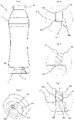
- Figure 1 :
- vue en coupe verticale d'un boîtier selon un premier exemple de réalisation de l'invention ;
- Figure 2 :
- vue en coupe du boîtier de la
figure 1 au niveau de l'ouverture ; - Figure 3 :
- la même vue que la
figure 2 , un bouchon étant introduit dans l'ouverture ; - Figure 4 :
- la même vue que la
figure 3 , les moyens de déformation étant déformés ; - Figure 5 :
- vue en perspective du fond du boîtier ;
- Figure 6 :
- une vue en coupe d'un boîtier selon un deuxième exemple de réalisation de l'invention.
- Figure 1 :
- vertical sectional view of a box according to a first embodiment of the invention;
- Figure 2:
- sectional view of the housing of the
figure 1 at the level of the opening; - Figure 3:
- the same view as
figure 2 , a plug being introduced into the opening; - Figure 4:
- the same view as
picture 3 , the deformation means being deformed; - Figure 5:
- perspective view of the case back;
- Figure 6:
- a sectional view of a box according to a second embodiment of the invention.
Le boîtier (1) de l'invention est destiné à être fermé par une valve et à être mis sous pression par introduction d'un gaz propulseur après remplissage en vue de former un récipient sous pression tel qu'un générateur d'aérosol ou un distributeur de produits pâteux.The housing (1) of the invention is intended to be closed by a valve and to be pressurized by introducing a propellant gas after filling in order to form a pressurized container such as an aerosol generator or a distributor of pasty products.
Pour des raisons de clarté de la description, il est fait appel à des références spatiales telles qu' « inférieur » et « supérieur ». Ces références se rapportent au boîtier lorsqu'il est dans la position représentée à la
Comme le montre la
Le fond (12) peut avoir dans sa partie centrale la forme d'un dôme (121) bombé vers l'intérieur du boîtier comme dans le présent exemple. Un trou (122) est réalisé dans le fond, par exemple dans ce dôme. Ce trou est destiné à être fermé directement (
Le trou (122) peut être réalisé directement lors de la formation du boîtier, ou bien être réalisé plus tard. Il peut être entouré d'un canal (123) qui s'étend vers l'intérieur et/ou vers l'extérieur du boîtier. Ce canal (123) est de préférence de même section transversale intérieure que le trou. Le diamètre du canal est choisi de telle sorte que le bouchon (2) peut y être facilement introduit. Ce canal peut être réalisé par introduction dans le trou d'un tube qui est ensuite fixé, de préférence par soudage, notamment par ultrason ou par soudage par friction circulaire (spin welding), aménageant ainsi le canal intérieur (et la zone de déformation qui sera évoquée plus bas). Le trou (122) et le canal (123), quand il est présent, forment une ouverture.The hole (122) can be made directly during the formation of the casing, or it can be made later. It may be surrounded by a channel (123) which extends inward and/or outward from the housing. This channel (123) is preferably of the same internal cross-section as the hole. The diameter of the channel is chosen so that the stopper (2) can be easily introduced therein. This channel can be made by inserting a tube into the hole which is then fixed, preferably by welding, in particular by ultrasound or by welding by circular friction (spin welding), thus arranging the internal channel (and the deformation zone which will be discussed below). The hole (122) and the channel (123), when present, form an opening.
Des moyens d'étanchéité sont prévus dans le canal ou au niveau du trou pour assurer l'étanchéité entre le bouchon et le boîtier. Dans une version simple, les moyens d'étanchéité sont constitués par le trou et/ou le canal eux-mêmes dont les dimensions sont choisies de telle sorte que le bouchon y est reçu serré. Cette solution peut être remplacée ou complétée par une nervure d'étanchéité (124) placée par exemple à l'extrémité du canal située le plus vers l'intérieur du boîtier. Cette nervure d'étanchéité (124) est d'un diamètre sensiblement plus petit que le diamètre du bouchon (2) de sorte que, même après mise sous pression, l'étanchéité soit assurée au moins au niveau de cette nervure. Le diamètre de la nervure est choisi certes sensiblement plus petit que celui du bouchon, mais pas trop petit non plus pour permettre l'introduction facile de celui-ci.Sealing means are provided in the channel or at the level of the hole to ensure sealing between the plug and the housing. In a simple version, the sealing means consist of the hole and/or the channel themselves, the dimensions of which are chosen so that the stopper is received tight therein. This solution can be replaced or supplemented by a sealing rib (124) placed for example at the end of the channel located furthest towards the inside of the casing. This sealing rib (124) is of a substantially smaller diameter than the diameter of the stopper (2) so that, even after pressurization, sealing is ensured at least at the level of this rib. The diameter of the rib is certainly chosen to be substantially smaller than that of the stopper, but not too small either to allow the easy introduction of the latter.
Du côté extérieur du boîtier, on a prévu une zone de déformation (125) placée soit directement adjacente au trou (122), soit à la suite du canal, si celui-ci s'étend vers l'extérieur du boîtier. La section transversale de cette zone de déformation (125) est de préférence identique à celle du trou (122) et/ou du canal (123). Elle peut également être choisie plus grande de telle sorte qu'elle n'empiète pas sur le trou (122) et/ou sur le canal (123). Cette zone de déformation sert, après déformation, à maintenir en place le bouchon (2). En effet, l'effet de retenue obtenu au niveau de la nervure d'étanchéité (124) permet dans des conditions normales avant mise sous pression de maintenir le bouchon (2) en place sans qu'il risque de se déplacer, notamment lors de l'introduction de l'aiguille de remplissage. Par contre, après mise sous pression, il peut régner à l'intérieur du récipient une pression pouvant dépasser 10 bars. La friction exercée par la nervure d'étanchéité (124) sur le bouchon ne serait pas suffisante pour empêcher ce dernier d'être expulsé du trou ou du canal. Après que le bouchon a été introduit dans le trou et/ou dans le canal, cette zone de déformation est déformée pour recouvrir le bord périphérique de la face frontale (21) du bouchon et former ainsi une surface de butée contre laquelle vient s'appuyer le bouchon lorsque le générateur d'aérosol est sous pression. Dans cette position, le bouchon est toujours en contact avec les moyens d'étanchéité, lorsqu'il y en a. La déformation peut être obtenue par exemple par déformation à chaud ou par tout autre moyen approprié. La zone déformée (126) forme un anneau ouvert en son centre (127), laissant le centre de la face frontale (21) du bouchon accessible aux moyens de mise sous pression, tels qu'une aiguille. La zone de déformation et la surface de butée qui résulte de sa déformation sont conçues de sorte à être perpendiculaires à l'axe du canal (123) et/ou parallèles au trou (122).On the outside of the casing, there is provided a deformation zone (125) placed either directly adjacent to the hole (122), or following the channel, if the latter extends towards the exterior of the casing. The cross section of this deformation zone (125) is preferably identical to that of the hole (122) and/or the channel (123). It can also be chosen larger so that it does not encroach on the hole (122) and/or on the channel (123). This deformation zone serves, after deformation, to hold the stopper (2) in place. Indeed, the retaining effect obtained at the level of the sealing rib (124) makes it possible under normal conditions before pressurization to hold the stopper (2) in place without there being any risk of it moving, in particular during introduction of the filling needle. On the other hand, after pressurization, there may prevail inside the container a pressure which may exceed 10 bars. The friction exerted by the sealing rib (124) on the plug would not be sufficient to prevent the latter from being expelled from the hole or channel. After the stopper has been introduced into the hole and/or into the channel, this deformation zone is deformed to cover the peripheral edge of the front face (21) of the stopper and thus form an abutment surface against which the cap when the aerosol generator is under pressure. In this position, the plug is still in contact with the sealing means, when there are any. The deformation can be obtained for example by hot deformation or by any other appropriate means. The deformed zone (126) forms an open ring at its center (127), leaving the center of the front face (21) of the stopper accessible to pressurizing means, such as a needle. The deformation zone and the abutment surface that results from its deformation are designed to be perpendicular to the axis of the channel (123) and/or parallel to the hole (122).
Une autre solution consiste non pas à prévoir une zone de déformation qui est déformée après introduction du bouchon, mais à surmouler la butée sur le trou ou sur la partie du canal saillant hors du boîtier après introduction du bouchon.Another solution consists not in providing a deformation zone which is deformed after introduction of the stopper, but in molding the abutment on the hole or on the part of the channel projecting outside the housing after introduction of the stopper.
Dans l'exemple illustré ici, le boîtier présente une symétrie axiale autour de l'axe vertical (A). L'ouverture, formée par le trou (122) et le canal (123), est réalisée de façon décentrée par rapport à cet axe afin de laisser libre le centre du dôme pour l'injection, lequel centre du dôme coïncide avec l'axe de symétrie (A). S'il n'y a pas de contrainte imposant un point d'injection au centre du dôme, il est bien sûr possible de placer le trou (122) et le canal (123) dans l'alignement de l'axe de symétrie (A).In the example illustrated here, the housing has axial symmetry around the vertical axis (A). The opening, formed by the hole (122) and the channel (123), is made off-center with respect to this axis in order to leave the center of the dome free for injection, which center of the dome coincides with the axis of symmetry (A). If there is no constraint imposing an injection point at the center of the dome, it is of course possible to place the hole (122) and the channel (123) in alignment with the axis of symmetry ( HAS).
Le canal de l'exemple de réalisation présenté ici s'étend uniquement vers l'intérieur du boîtier et parallèlement à l'axe de symétrie (A). Seule la partie de déformation dépasse du dôme vers l'extérieur du boîtier. Le trou (122) et la partie de déformation (125) sont placés dans un retrait (128) formé dans le dôme (121). La paroi du retrait au niveau de l'ouverture (122, 123) est perpendiculaire à l'axe de symétrie (A). En plaçant le canal parallèlement à l'axe de symétrie (A) du boîtier, on facilite la mise en place du bouchon (2) durant l'assemblage et la mise sous pression, notamment lorsque cette mise sous pression est réalisée par introduction d'une aiguille à travers le plug. Il serait cependant également envisageable que l'axe du canal soit par exemple perpendiculaire à la tangente au dôme au niveau du trou (122).The channel of the embodiment shown here extends only towards the inside of the housing and parallel to the axis of symmetry (A). Only the deformation part protrudes from the dome towards the outside of the case. The hole (122) and the deformation part (125) are placed in a recess (128) formed in the dome (121). The wall of the recess at the level of the opening (122, 123) is perpendicular to the axis of symmetry (A). By placing the channel parallel to the axis of symmetry (A) of the housing, it facilitates the installation of the plug (2) during assembly and pressurization, in particular when this pressurization is carried out by introducing a needle through the plug. However, it would also be possible for the axis of the channel to be, for example, perpendicular to the tangent to the dome at the level of the hole (122).
Le boîtier muni de son bouchon selon le premier exemple de réalisation peut être fabriqué de la façon suivante :
- A Fabrication du boîtier :
- a) fabrication du boîtier, par exemple par soufflage, avec réalisation du fond (12), de la paroi tubulaire (11) et du col (13), une ouverture constituée d'au moins un trou (122) étant réalisée dans le fond, soit directement, soit lors d'une sous-étape ultérieure. L'ouverture peut être complétée par le canal (123) ;
- b) réalisation de moyens d'étanchéité (124) placés dans le trou (122) ou le canal (123) s'il y en a un, ces moyens d'étanchéité assurant l'étanchéité entre le bouchon (2) et le boîtier (1) après que le bouchon a été introduit ; et
- c) réalisation du côté de la face du fond (12) dirigée vers l'extérieur du boîtier (1) d'une zone de déformation (125) placée dans le prolongement soit du trou (122) soit du canal (123) s'il y en a un qui saille hors du boîtier. La zone de déformation est conçue pour être déformée après introduction d'un bouchon dans l'ouverture pour former une surface de butée (126) pour le bouchon en vue d'empêcher ce dernier de se déplacer vers l'extérieur du boîtier. Cette zone de déformation constitue les moyens de retenue quand ils sont dans leur forme initiale inactive.
- B Mise en place et blocage du bouchon, soit directement lors de la fabrication du boîtier, soit ultérieurement, notamment lors du remplissage du boîtier en vue de former un flacon sous pression :
- d) introduction du bouchon dans le trou (122) et/ou le canal (123) pour fermer l'ouverture ;
- e) puis activation des moyens de retenue par déformation de la zone de déformation en bloquant le bouchon de sorte qu'il ne puisse pas ressortir après mise sous pression du flacon.
- A Construction of the case:
- a) manufacture of the case, for example by blow molding, with production of the bottom (12), of the tubular wall (11) and of the neck (13), an opening consisting of at least one hole (122) being made in the bottom , either directly or in a later sub-step. The opening can be completed by the channel (123);
- b) production of sealing means (124) placed in the hole (122) or the channel (123) if there is one, these sealing means providing sealing between the plug (2) and the housing (1) after the plug has been inserted; and
- c) realization on the side of the face of the bottom (12) directed towards the exterior of the casing (1) of a deformation zone (125) placed in the extension either of the hole (122) or of the channel (123) s' there is one sticking out of the case. The deformation zone is designed to be deformed after inserting a plug into the opening to form an abutment surface (126) for the plug to prevent the plug from moving out of the housing. This deformation zone constitutes the retaining means when they are in their initial inactive form.
- B Fitting and locking the stopper, either directly during manufacture of the case, or later, in particular when filling the case in order to form a pressurized bottle:
- d) inserting the plug into the hole (122) and/or the channel (123) to close the opening;
- e) then activation of the retaining means by deformation of the deformation zone by blocking the stopper so that it cannot come out after the bottle has been pressurized.
Pour faciliter l'étape d'introduction du bouchon lorsque l'ouverture n'est pas centrée sur l'axe (A), il est possible de prévoir des moyens d'indexage permettant d'orienter correctement le boîtier afin que le trou et le canal soient dans l'alignement de l'outil de mise en place du bouchon. Le retrait (128) peut remplir cette fonction. Il est cependant également possible de prévoir dans le fond (12) un retrait ou une saillie spécifique, non représenté dans les figures.To facilitate the step of inserting the stopper when the opening is not centered on the axis (A), it is possible to provide indexing means making it possible to correctly orient the case so that the hole and the channel are aligned with the plug fitting tool. The recess (128) can perform this function. However, it is also possible to provide in the bottom (12) a specific recess or projection, not shown in the figures.
Dans une variante de réalisation non représentée, la déformation de la zone de déformation (125) est remplacée par la fixation au boîtier, notamment par soudage, d'une rondelle dont le diamètre extérieur est supérieur au diamètre de l'ouverture (trou et/ou canal) et dont le diamètre intérieur est inférieur au diamètre du bouchon. Le bord périphérique de la rondelle est fixé au boîtier autour de l'ouverture. Le bord intérieur de la rondelle constitue les moyens de retenue.In a variant embodiment not shown, the deformation of the deformation zone (125) is replaced by the attachment to the housing, in particular by welding, of a washer whose outer diameter is greater than the diameter of the opening (hole and/ or channel) and whose internal diameter is less than the diameter of the plug. The peripheral edge of the washer is attached to the housing around the opening. The inner edge of the washer constitutes the retaining means.
Dans le deuxième exemple de réalisation présenté à la
Le procédé de fabrication de cette variante de boîtier peut être le suivant :
- A' Fabrication du boîtier :
a') fabrication du boîtier, par exemple par soufflage, avec réalisation du fond (12), de la paroi tubulaire (11) et du col (13), un trou (122') étant réalisé dans le fond, soit directement, soit lors d'une sous-étape ultérieure ; - B' Fabrication de l'unité préassemblée :
- b') réalisation de moyens d'étanchéité (124') dans le canal (123'), ces moyens d'étanchéité assurant l'étanchéité entre le bouchon (2') et le boîtier (1') après que l'unité préassemblée a été fixée au boîtier et le bouchon introduit dans le canal ; et
- c') réalisation des moyens de retenue placés dans le prolongement du canal (123'). Ils forment une surface de butée (126') pour le bouchon en vue d'empêcher ce dernier de se déplacer vers l'extérieur du boîtier. Les moyens de retenue (126') peuvent être obtenus par déformation d'une zone de déformation comme dans le cas du premier exemple de réalisation, cette déformation (qui n'est pas l'activation à proprement parler) pouvant être réalisée après introduction du bouchon dans le canal. Les moyens de retenue peuvent également être directement formés en même temps que le canal (123'), sans qu'il soit nécessaire que le bouchon soit déjà introduit dans le canal.
- d1') introduction du bouchon (2') dans le canal (123') de sorte qu'il coopère au moins avec les moyens d'étanchéité. S'il ne coopère pas encore avec les moyens de retenue, le bouchon sera déplacé jusqu'à la butée (126') au plus tard lors de la mise sous pression du récipient.
- C' Insertion et fixation de l'unité préassemblée dans le trou
- d2') Insertion de l'unité préassemblée dans le trou (122'). L'ouverture est ainsi fermée indirectement par le bouchon contenu dans l'unité préassemblée.
- e') Fixation de l'unité préassemblée sur le boîtier, par exemple par soudage, de préférence par spin welding. Cette étape peut être réalisée avant remplissage du flacon, ou après remplissage. Le soudage de l'unité préassemblée sur le boîtier active les moyens de retenue (surface de butée) jusque-là inactifs.
- A' Manufacture of the case:
a') manufacture of the case, for example by blow molding, with production of the bottom (12), of the tubular wall (11) and of the neck (13), a hole (122') being made in the bottom, either directly or during a subsequent sub-step; - B' Manufacture of the pre-assembled unit:
- b') production of sealing means (124') in the channel (123'), these sealing means ensuring the sealing between the plug (2') and the casing (1') after the preassembled unit was attached to the housing and the plug introduced into the channel; and
- c') production of retaining means placed in the extension of the channel (123'). They form an abutment surface (126') for the cap to prevent the cap from moving out of the housing. The retaining means (126') can be obtained by deformation of a deformation zone as in the case of the first exemplary embodiment, this deformation (which is not activation strictly speaking) being able to be carried out after introduction of the plug in the channel. The retaining means can also be formed directly at the same time as the channel (123'), without it being necessary for the plug to be already introduced into the channel.
- d1') introduction of the plug (2') into the channel (123') so that it cooperates at least with the sealing means. If it does not yet cooperate with the retaining means, the stopper will be moved as far as the stop (126') at the latest when the container is pressurized.
- C' Inserting and fixing the pre-assembled unit in the hole
- d2') Inserting the pre-assembled unit into the hole (122'). The opening is thus closed indirectly by the plug contained in the pre-assembled unit.
- e′) Fixing the pre-assembled unit to the casing, for example by welding, preferably by spin welding. This step can be carried out before filling the bottle, or after filling. Welding the pre-assembled unit to the housing activates the previously inactive retaining means (stop surface).
Comme on le voit, que ce soit dans le premier exemple de réalisation ou dans le second, on obtient un boîtier (1, 1') qui se compose notamment
- d'un fond (12) comprenant :
- ∘ une ouverture (122, 123, 122', 123') destinée à être fermée directement ou indirectement par un bouchon (2, 2') ;
- ∘ des moyens d'étanchéité (124, 124') pour assurer l'étanchéité entre le bouchon (2, 2') et le boîtier (1, 1') lorsque le boîtier est muni d'un bouchon ; et
- de moyens de retenue (126, 126') pour retenir, lorsque le récipient est sous pression, un bouchon (2, 2') fermant ladite ouverture, les moyens de retenue se présentant sous une forme initiale inactive (125) et devant, pour remplir leur fonction, être activés (126) après que l'ouverture a été fermée directement ou indirectement par un bouchon. Les moyens de retenue (126, 126') sont distincts du bouchon. En effet, tant que le récipient n'est pas sous pression, il serait possible de repousser le bouchon vers l'intérieur du récipient en surmontant les effets des moyens d'étanchéité (124, 124'). Quand le bouchon (2) est introduit dans le trou (122) et/ou le canal (123), l'ouverture est fermée directement par le bouchon. Par contre, quand le bouchon est intégré dans une unité préassemblée, c'est toute l'unité préassemblée qui ferme l'ouverture : l'ouverture est indirectement fermée par le bouchon avec interposition du canal (123').
- a bottom (12) comprising:
- ∘ an opening (122, 123, 122', 123') intended to be closed directly or indirectly by a plug (2, 2');
- ∘ sealing means (124, 124') to ensure sealing between the cap (2, 2') and the box (1, 1') when the box is provided with a plug; and
- retaining means (126, 126') for retaining, when the container is under pressure, a stopper (2, 2') closing said opening, the retaining means being in an inactive initial form (125) and in front, for perform their function, be activated (126) after the opening has been closed directly or indirectly by a plug. The retaining means (126, 126') are separate from the plug. Indeed, as long as the container is not under pressure, it would be possible to push the stopper towards the interior of the container by overcoming the effects of the sealing means (124, 124'). When the plug (2) is introduced into the hole (122) and/or the channel (123), the opening is closed directly by the plug. On the other hand, when the stopper is integrated into a preassembled unit, it is the entire preassembled unit which closes the opening: the opening is indirectly closed by the stopper with the interposition of the channel (123').
De même pour le procédé, on retrouve dans tous les cas les étapes de
- a) réalisation d'un fond (12) muni d'une ouverture (122, 123, 122') destinée à être fermée directement ou indirectement par un bouchon (2, 2');
- b) réalisation de moyens d'étanchéité (124, 124') pour assurer l'étanchéité entre le bouchon (2, 2') et le boîtier (1, 1') lorsque le boîtier est muni d'un bouchon ;
- c) réalisation de moyens de retenue (125, 126') pour retenir, lorsque le récipient est sous pression, un bouchon (2, 2') fermant ladite ouverture,
les moyens de retenue se présentant sous une forme initiale inactive (125) ; - d) introduction d'un bouchon (2, 2') dans le boîtier pour fermer l'ouverture (122, 123 ; 122') ;
- e) puis activation des moyens de retenue (125) pour former une surface de butée (126, 126') empêchant le bouchon de sortir du boîtier.
- a) production of a bottom (12) provided with an opening (122, 123, 122') intended to be closed directly or indirectly by a stopper (2, 2');
- b) production of sealing means (124, 124') to provide sealing between the plug (2, 2') and the housing (1, 1') when the housing is fitted with a plug;
- c) production of retaining means (125, 126') for retaining, when the container is under pressure, a stopper (2, 2') closing said opening,
the retaining means being in an inactive initial form (125); - d) inserting a plug (2, 2') into the housing to close the opening (122, 123; 122');
- e) then activation of the retaining means (125) to form an abutment surface (126, 126') preventing the plug from coming out of the housing.
Dans les exemples présentés ici, les moyens d'étanchéité et les moyens de retenue sont des éléments distincts. Les moyens de retenue pallient le risque de déformation, même minime, du fond sous l'effet de la pression régnant dans le récipient aérosol. Les moyens d'étanchéité n'ont donc pas à remplir en plus la fonction de retenir le bouchon contre l'effet de la pression régnant dans le récipient.In the examples presented here, the sealing means and the retaining means are separate elements. The retaining means overcome the risk of deformation, even minimal, of the bottom under the effect of the pressure prevailing in the aerosol container. The sealing means therefore do not have to additionally perform the function of retaining the stopper against the effect of the pressure prevailing in the container.
L'invention est destinée en premier lieu à un boîtier en matière plastique. Elle est particulièrement intéressante pour les récipients sous pression multicompartiment, notamment dans le cas des valves à poche, les valves à double poche ou les récipients à piston. On peut également envisager, notamment dans le cas des produits à haute viscosité, de remplir le récipient via l'ouverture avant de placer le bouchon (ou l'unité préassemblée) et d'activer les moyens de retenue et de mettre sous pression, permettant ainsi d'éviter un remplissage via la valve aux passages étroits.The invention is intended primarily for a housing made of plastic material. It is particularly interesting for multi-compartment pressure vessels, in particular in the case of pocket valves, double pocket valves or piston containers. It is also possible, especially in the case of high viscosity products, to fill the container via the opening before placing the cap (or the pre-assembled unit) and activating the retaining means and pressurizing, allowing thus avoiding filling via the valve with narrow passages.
Dans la présente invention, les moyens de retenue du bouchon dans le boîtier se présentent d'abord sous forme inactive et doivent être activés après introduction du bouchon dans le boîtier pour remplir leur fonction :
- 1 ère variante : le bouchon (2) introduit dans le trou (122) ou dans le canal (123) ne résisterait pas à la pression régnant dans le récipient sous pression. Il faut donc, pour activer les moyens de retenue, déformer la zone de déformation (125) ou fixer une rondelle autour du trou (122) ou à l'extrémité inférieure du canal (123) de sorte que la zone déformée (126) ou la rondelle empiète sur le trou et/ou le canal en formant une surface de butée pour le bouchon (2).
- 2 ème variante : le bouchon (2') introduit dans le trou (122') via l'unité préassemblée serait expulsé hors du boîtier sous pression si l'unité préassemblée n'est pas préalablement solidarisée avec le boîtier, et ce, bien que l'unité préassemblée soit déjà munie de la surface de butée (126'). Ce n'est qu'après fixation sur le boîtier (= activation) de l'unité préassemblée que cette surface de butée (126') peut remplir sa fonction.
- 1st variant: the stopper (2) introduced into the hole (122) or into the channel (123) would not resist the pressure prevailing in the pressure vessel. It is therefore necessary, to activate the retaining means, to deform the deformation zone (125) or to fix a washer around the hole (122) or at the lower end of the channel (123) so that the deformed zone (126) or the washer impinges on the hole and/or the channel forming an abutment surface for the plug (2).
- 2 nd variant: the plug (2') introduced into the hole (122') via the preassembled unit would be expelled from the box under pressure if the preassembled unit is not secured to the box beforehand, and this, although the pre-assembled unit is already provided with the abutment surface (126'). It is only after attachment to the housing (= activation) of the pre-assembled unit that this abutment surface (126') can fulfill its function.
- 1, 1'1, 1'
-
Boîtier
11 Paroi tubulaire
12 Fond
121, 121' Dôme
122, 122' Trou
123, 123' Canal
124, 124' Nervure d'étanchéité
125 Zone de déformation
126, 126' Zone déformée/surface de butée
127, 127' Centre de la zone déformée/surface de butée
128, 128' Retrait
129' Surface de fixation
13 ColHousing
11 Tubular wall
12 Background
121, 121' Dome
122, 122' Hole
123, 123' Channel
124, 124' Sealing Rib
125 Crumple Zone
126, 126' Deformed area/abutment surface
127, 127' Center of deformed area/abutment surface
128, 128' Withdrawal
129' Mounting area
13 Pass - 22
-
Bouchon élastomère (plug)
21, 21' Face frontale du bouchonElastomeric plug (plug)
21, 21' End face of plug - AHAS
- Axe de symétrieAxis of symmetry
Claims (21)
- Housing (1, 1') for a pressurized container, comprising in particular:- a bottom (12) comprising:∘ an opening (122, 123, 122') intended to be closed by a stopper (2, 2');∘ sealing means (124, 124') to ensure sealing between the stopper (2, 2') and the housing (1, 1') when the housing is provided with a stopper; and- retaining means (125, 126, 126') to retain, when the container is pressurized, a stopper (2, 2') closing the opening,wherein the retaining means (125, 126, 126') are distinct from the stopper (2) and are in an inactive initial form (125) and must, in order to fulfill their function, be activated (126, 126') after the opening has been closed with a stopper, characterized in that the activation of the retaining means is carried out either by deformation of the retaining means or by welding.
- Housing (1, 1') according to claim 1, characterized in that, before and after their activation, the retaining means (125, 126, 126') are located on a face of the bottom (12) located outside the housing.
- Housing (1) according to claim 1 or 2, characterized in that the opening comprises a hole (122) preferably surrounded by a channel (123) extending toward the inside and/or toward the outside of the housing (1).
- Housing (1) according to claim 3, characterized in that the sealing means are constituted by a sealing rib (124) placed in the channel (123), in particular at an end of the channel located the most toward the inside of the housing (1), and/or placed at the hole (122).
- Housing (1) according to one of the preceding claims, characterized in that the retaining means are constituted by- a deformation zone (125) placed in the extension of the opening, on the side of a face of the bottom (12) oriented toward the outside of the housing (1), the deformation zone being designed to be deformed, after introduction of a stopper (2) in the opening, to form an abutment surface (126) for the stopper to prevent the latter from moving toward the outside of the housing, or by- a washer intended to be fixed, preferably welded, to the housing in the extension of the opening on the side of the face of the bottom oriented toward the outside of the housing after introduction of a stopper (2) into the opening, the washer being designed to form, after being fixed, an abutment surface for the stopper in order to prevent the latter from moving toward the outside of the housing.
- Housing (1) according to one of the preceding claims, characterized in that the opening (122, 123) is provided with a stopper (2) and in that the retaining means (126) are activated.
- Housing (1') according to claim 1 or 2, characterized in that the opening comprises a hole (122'), and in that the housing comprises a preassembled unit separate from the housing, and intended to be introduced into the hole and to be fixed, preferably welded, to the housing, said preassembled unit being constituted by a channel (123') provided with sealing means (124') and retaining means (126'), and a stopper (2') introduced into the channel and cooperating with the sealing means and the retaining means (126'), the retaining means preferably comprising a fixing surface (129') for fixing the preassembled unit to the housing.
- Housing (1') according to the preceding claim, characterized in that the sealing means are constituted by a sealing rib (124') placed in the channel (123'), in particular at an end of the channel located the most toward the inside of the housing (1'), and/or the retaining means are constituted by an abutment surface (126') preventing the stopper from moving toward the outside of the housing when the preassembled unit is fixed to the housing, and/or in that the retaining means are constituted by a washer fixed, preferably welded, in the extension of the channel, on the side of a face of the bottom oriented toward the outside of the housing, the washer being designed to form, after being fixed, an abutment surface for the stopper in order to prevent the latter from moving toward the outside of the housing.
- Housing (1') according to one of claims 7 or 8, characterized in that the preassembled unit (123', 124', 126', 129', 2') is introduced into the hole (122') and is fixed, preferably welded, to the housing (1').
- Housing (1, 1') according to one of claims 6 to 9, characterized in that the stopper (2, 2') is made in an elastomeric material, preferably nitrile.
- Housing (1, 1') according to one of claims 6 to 9, characterized in that the stopper is a stopper of the non-return type.
- Housing (1, 1') according to one of the preceding claims, characterized in that the housing, with the exception of the stopper if the housing is fitted with a stopper, is constituted by a part in plastic material, preferably thermoplastic, in particular PET, PEN or nylon, or a mixture thereof, said part preferably being obtained by blow molding.
- Housing (1, 1') according to one of the preceding claims, characterized in that the opening (122, 123, 122') and the retaining means (125, 126, 126') are arranged at an offcenter point of the bottom (12), indexing means preferably being provided to facilitate the orientation of the housing (1, 1') when closing the opening with a stopper (2, 2').
- Housing (1, 1') according to one of the preceding claims, characterized in that the bottom (12) has, in its central portion, the shape of a dome (121, 121') curved preferably toward the inside of the housing.
- Housing (1, 1') according to one of the preceding claims, characterized in that the opening (122, 123, 122') and the retaining means (125, 126, 126') are placed in a recess (128, 128') made in the bottom (12), the recess preferably being made in a dome (121, 121') forming the central portion of the bottom.
- Method of manufacturing a housing (1, 1') according to one of the preceding claims, comprising the following steps:a) making a bottom (12) provided with an opening (122, 123, 122') intended to be closed by a stopper (2, 2');b) making sealing means (124, 124') to ensure sealing between the stopper (2, 2') and the housing (1, 1') when the housing is provided with a stopper; andc) making retaining means (125, 126, 126') to retain, when the container is pressurized, a stopper (2, 2') closing the opening,and including the steps consisting of- closing the opening by a stopper (2, 2'),- then activating the retaining means (126, 126'), which are in an inactive initial form (125), wherein the activation of the retaining means is carried out either by deformation of the retaining means or by welding.
- Method according to claim 16, characterized in that during step a), a hole (122, 122') is made in the bottom (12), wherein the bottom (12) and the hole (122, 122') can be made in the same step or in two successive steps.
- Method according to claim 16 or 17, characterized in that during step a) or in a subsequent step, a channel (123) is placed around the hole (122), which channel extends toward the inside and/or the outside of the housing, wherein the hole (122) can be made during the installation of the channel (123).
- Method according to one of claims 16 to 18, characterized by the following additional steps:d) introducing a stopper (2) into the housing to close the opening (122, 123);e) then activating the initially inactive retaining means (125) to form an abutment surface (126) preventing the stopper from coming out of the housing (1, 1'), wherein the activation can consist in deforming a deformation zone (125) or in fixing, preferably welding, a washer.
- Method according to one of claims 16 to 17, characterized in that a preassembled unit, constituted by a channel (123') provided with sealing means (124') and an abutment surface, and a stopper (2) introduced into the channel and cooperating with the sealing means, is introduced into the hole (122'), then fixed to the housing, preferably by welding, in particular by spin welding, so that the preassembled unit with the stopper placed therein closes the hole (122').
- Method according to one of claims 16 to 20, characterized in that the housing is made by blow molding.
Applications Claiming Priority (2)
| Application Number | Priority Date | Filing Date | Title |
|---|---|---|---|
| FR1856672A FR3084065B1 (en) | 2018-07-18 | 2018-07-18 | CASE FOR PRESSURE CONTAINER |
| PCT/EP2019/069053 WO2020016199A1 (en) | 2018-07-18 | 2019-07-15 | Housing for a pressurised container |
Publications (2)
| Publication Number | Publication Date |
|---|---|
| EP3823764A1 EP3823764A1 (en) | 2021-05-26 |
| EP3823764B1 true EP3823764B1 (en) | 2022-08-17 |
Family
ID=63684132
Family Applications (1)
| Application Number | Title | Priority Date | Filing Date |
|---|---|---|---|
| EP19739993.4A Active EP3823764B1 (en) | 2018-07-18 | 2019-07-15 | Housing for a pressurised container |
Country Status (7)
| Country | Link |
|---|---|
| US (1) | US20210292080A1 (en) |
| EP (1) | EP3823764B1 (en) |
| AR (1) | AR115810A1 (en) |
| CA (1) | CA3107149C (en) |
| FR (1) | FR3084065B1 (en) |
| MX (1) | MX2020014133A (en) |
| WO (1) | WO2020016199A1 (en) |
Citations (1)
| Publication number | Priority date | Publication date | Assignee | Title |
|---|---|---|---|---|
| FR2789662B1 (en) * | 1999-02-11 | 2001-03-16 | Cebal | TWO-CHAMBER ALUMINUM ALLOY PRESSURE DISTRIBUTOR HOUSING |
Family Cites Families (12)
| Publication number | Priority date | Publication date | Assignee | Title |
|---|---|---|---|---|
| US3131828A (en) * | 1961-10-18 | 1964-05-05 | Waldherr Wilhelm | Refillable container having filling plug improvement |
| US3356257A (en) * | 1965-09-16 | 1967-12-05 | Midwest Consultants Inc | Safety plug for pressure vessels |
| US3422837A (en) * | 1966-12-27 | 1969-01-21 | Eaton Yale & Towne | Filling valve structure for pressurized containers |
| AU425398B2 (en) * | 1970-03-09 | 1972-06-21 | Trenton (Aust) Pty. Limited | An aerosol container |
| JPS60110669A (en) * | 1983-11-12 | 1985-06-17 | 株式会社林原生物化学研究所 | Pressure discharging vessel and manufacture thereof |
| US4658979A (en) * | 1986-01-13 | 1987-04-21 | American Can Company | Propellant filling and sealing valve |
| US4993602A (en) * | 1989-06-07 | 1991-02-19 | Prd, Inc. | Pressure relief device for a pressurized container |
| JPH03162273A (en) * | 1989-11-09 | 1991-07-12 | Yoshida Kogyo Kk <Ykk> | Pressure-discharge container for fluid substance |
| US5279907A (en) * | 1992-05-11 | 1994-01-18 | Emerson Electric Co. | Safety vent for a container and method of making the same |
| US5944211A (en) * | 1997-08-26 | 1999-08-31 | Anchor Hocking Plastics/Plastics Inc. | Container system including an air evacuation valve |
| US8925579B2 (en) * | 2006-03-02 | 2015-01-06 | Pacific Bag, Inc. | Pressure relief valve |
| EP2998241A1 (en) * | 2014-09-18 | 2016-03-23 | Thomas GmbH | Attachment of a valve body in the valve cup of an aerosol container |
-
2018
- 2018-07-18 FR FR1856672A patent/FR3084065B1/en not_active Expired - Fee Related
-
2019
- 2019-07-15 WO PCT/EP2019/069053 patent/WO2020016199A1/en active Application Filing
- 2019-07-15 US US17/260,785 patent/US20210292080A1/en active Pending
- 2019-07-15 EP EP19739993.4A patent/EP3823764B1/en active Active
- 2019-07-15 CA CA3107149A patent/CA3107149C/en active Active
- 2019-07-15 MX MX2020014133A patent/MX2020014133A/en unknown
- 2019-07-18 AR ARP190102025A patent/AR115810A1/en active IP Right Grant
Patent Citations (1)
| Publication number | Priority date | Publication date | Assignee | Title |
|---|---|---|---|---|
| FR2789662B1 (en) * | 1999-02-11 | 2001-03-16 | Cebal | TWO-CHAMBER ALUMINUM ALLOY PRESSURE DISTRIBUTOR HOUSING |
Also Published As
| Publication number | Publication date |
|---|---|
| BR112021000238A2 (en) | 2021-04-06 |
| CA3107149C (en) | 2021-07-06 |
| EP3823764A1 (en) | 2021-05-26 |
| US20210292080A1 (en) | 2021-09-23 |
| CA3107149A1 (en) | 2020-01-23 |
| AR115810A1 (en) | 2021-03-03 |
| FR3084065B1 (en) | 2021-10-01 |
| WO2020016199A1 (en) | 2020-01-23 |
| MX2020014133A (en) | 2021-11-22 |
| FR3084065A1 (en) | 2020-01-24 |
Similar Documents
| Publication | Publication Date | Title |
|---|---|---|
| EP3310690B1 (en) | Method for manufacturing an aerosol valve, and aerosol valve | |
| EP2822873B1 (en) | Insert for fixing a bag within a bottle | |
| EP2024256B1 (en) | Two-way valve | |
| WO2011154666A1 (en) | Two-material capsule | |
| FR2465655A1 (en) | RAPID COUPLING AND CONNECTING TUBE FOR VALVE DEFORMABLE BY CRUSHING | |
| WO2007074274A1 (en) | Ring for aerosol dispenser valve | |
| EP3253685B1 (en) | Fitting member for fixing a pouch within a pressurized dispenser and method for charging a pressurized dispenser comprising such a pouch | |
| FR2776991A1 (en) | Fluid container and dispenser pump | |
| EP3823764B1 (en) | Housing for a pressurised container | |
| WO2015049429A1 (en) | Measuring cap | |
| FR2913677A1 (en) | DECAPSULATOR FOR BOTTLE CAPSULE OF A BOTTLE. | |
| WO2003074373A1 (en) | Package comprising a pressure-deformable container and method for making same | |
| CA3143113C (en) | Valve for pressurised container | |
| EP4244157A1 (en) | Diffuser for aerosol generator | |
| CA2422754A1 (en) | Pourer with improved locking and cap equipped with same | |
| EP3917683B1 (en) | Fluid product reservoir | |
| FR3037048B1 (en) | DOSING VALVE | |
| FR2886924A1 (en) | IRREMPLISSABILITY DEVICE FOR RECOVERY TUBE, TYPICALLY BOTTLE, AND COMPOSITE BUCKET CAPSULE COMPRISING SAID DEVICE | |
| EP4116216A1 (en) | Device for sealing a tank of a liquid product | |
| EP2774865B1 (en) | System for attaching an ornamental element to the neck of a carafe | |
| EP2146923A2 (en) | Closure cover for container designed for storing carbonate liquids, and container provided with such a cover |
Legal Events
| Date | Code | Title | Description |
|---|---|---|---|
| STAA | Information on the status of an ep patent application or granted ep patent |
Free format text: STATUS: UNKNOWN |
|
| STAA | Information on the status of an ep patent application or granted ep patent |
Free format text: STATUS: THE INTERNATIONAL PUBLICATION HAS BEEN MADE |
|
| STAA | Information on the status of an ep patent application or granted ep patent |
Free format text: STATUS: THE INTERNATIONAL PUBLICATION HAS BEEN MADE |
|
| PUAI | Public reference made under article 153(3) epc to a published international application that has entered the european phase |
Free format text: ORIGINAL CODE: 0009012 |
|
| STAA | Information on the status of an ep patent application or granted ep patent |
Free format text: STATUS: REQUEST FOR EXAMINATION WAS MADE |
|
| 17P | Request for examination filed |
Effective date: 20210202 |
|
| AK | Designated contracting states |
Kind code of ref document: A1 Designated state(s): AL AT BE BG CH CY CZ DE DK EE ES FI FR GB GR HR HU IE IS IT LI LT LU LV MC MK MT NL NO PL PT RO RS SE SI SK SM TR |
|
| DAV | Request for validation of the european patent (deleted) | ||
| DAX | Request for extension of the european patent (deleted) | ||
| GRAP | Despatch of communication of intention to grant a patent |
Free format text: ORIGINAL CODE: EPIDOSNIGR1 |
|
| STAA | Information on the status of an ep patent application or granted ep patent |
Free format text: STATUS: GRANT OF PATENT IS INTENDED |
|
| INTG | Intention to grant announced |
Effective date: 20211105 |
|
| GRAJ | Information related to disapproval of communication of intention to grant by the applicant or resumption of examination proceedings by the epo deleted |
Free format text: ORIGINAL CODE: EPIDOSDIGR1 |
|
| STAA | Information on the status of an ep patent application or granted ep patent |
Free format text: STATUS: REQUEST FOR EXAMINATION WAS MADE |
|
| GRAP | Despatch of communication of intention to grant a patent |
Free format text: ORIGINAL CODE: EPIDOSNIGR1 |
|
| STAA | Information on the status of an ep patent application or granted ep patent |
Free format text: STATUS: GRANT OF PATENT IS INTENDED |
|
| INTC | Intention to grant announced (deleted) | ||
| INTG | Intention to grant announced |
Effective date: 20220316 |
|
| RAP3 | Party data changed (applicant data changed or rights of an application transferred) |
Owner name: LINDAL FRANCE SAS |
|
| GRAS | Grant fee paid |
Free format text: ORIGINAL CODE: EPIDOSNIGR3 |
|
| GRAA | (expected) grant |
Free format text: ORIGINAL CODE: 0009210 |
|
| STAA | Information on the status of an ep patent application or granted ep patent |
Free format text: STATUS: THE PATENT HAS BEEN GRANTED |
|
| AK | Designated contracting states |
Kind code of ref document: B1 Designated state(s): AL AT BE BG CH CY CZ DE DK EE ES FI FR GB GR HR HU IE IS IT LI LT LU LV MC MK MT NL NO PL PT RO RS SE SI SK SM TR |
|
| REG | Reference to a national code |
Ref country code: CH Ref legal event code: EP |
|
| REG | Reference to a national code |
Ref country code: DE Ref legal event code: R096 Ref document number: 602019018411 Country of ref document: DE |
|
| REG | Reference to a national code |
Ref country code: IE Ref legal event code: FG4D Free format text: LANGUAGE OF EP DOCUMENT: FRENCH |
|
| REG | Reference to a national code |
Ref country code: AT Ref legal event code: REF Ref document number: 1511812 Country of ref document: AT Kind code of ref document: T Effective date: 20220915 |
|
| REG | Reference to a national code |
Ref country code: NL Ref legal event code: FP |
|
| REG | Reference to a national code |
Ref country code: LT Ref legal event code: MG9D |
|
| PG25 | Lapsed in a contracting state [announced via postgrant information from national office to epo] |
Ref country code: SE Free format text: LAPSE BECAUSE OF FAILURE TO SUBMIT A TRANSLATION OF THE DESCRIPTION OR TO PAY THE FEE WITHIN THE PRESCRIBED TIME-LIMIT Effective date: 20220817 Ref country code: RS Free format text: LAPSE BECAUSE OF FAILURE TO SUBMIT A TRANSLATION OF THE DESCRIPTION OR TO PAY THE FEE WITHIN THE PRESCRIBED TIME-LIMIT Effective date: 20220817 Ref country code: PT Free format text: LAPSE BECAUSE OF FAILURE TO SUBMIT A TRANSLATION OF THE DESCRIPTION OR TO PAY THE FEE WITHIN THE PRESCRIBED TIME-LIMIT Effective date: 20221219 Ref country code: NO Free format text: LAPSE BECAUSE OF FAILURE TO SUBMIT A TRANSLATION OF THE DESCRIPTION OR TO PAY THE FEE WITHIN THE PRESCRIBED TIME-LIMIT Effective date: 20221117 Ref country code: LV Free format text: LAPSE BECAUSE OF FAILURE TO SUBMIT A TRANSLATION OF THE DESCRIPTION OR TO PAY THE FEE WITHIN THE PRESCRIBED TIME-LIMIT Effective date: 20220817 Ref country code: LT Free format text: LAPSE BECAUSE OF FAILURE TO SUBMIT A TRANSLATION OF THE DESCRIPTION OR TO PAY THE FEE WITHIN THE PRESCRIBED TIME-LIMIT Effective date: 20220817 Ref country code: FI Free format text: LAPSE BECAUSE OF FAILURE TO SUBMIT A TRANSLATION OF THE DESCRIPTION OR TO PAY THE FEE WITHIN THE PRESCRIBED TIME-LIMIT Effective date: 20220817 |
|
| REG | Reference to a national code |
Ref country code: AT Ref legal event code: MK05 Ref document number: 1511812 Country of ref document: AT Kind code of ref document: T Effective date: 20220817 |
|
| PG25 | Lapsed in a contracting state [announced via postgrant information from national office to epo] |
Ref country code: PL Free format text: LAPSE BECAUSE OF FAILURE TO SUBMIT A TRANSLATION OF THE DESCRIPTION OR TO PAY THE FEE WITHIN THE PRESCRIBED TIME-LIMIT Effective date: 20220817 Ref country code: IS Free format text: LAPSE BECAUSE OF FAILURE TO SUBMIT A TRANSLATION OF THE DESCRIPTION OR TO PAY THE FEE WITHIN THE PRESCRIBED TIME-LIMIT Effective date: 20221217 Ref country code: HR Free format text: LAPSE BECAUSE OF FAILURE TO SUBMIT A TRANSLATION OF THE DESCRIPTION OR TO PAY THE FEE WITHIN THE PRESCRIBED TIME-LIMIT Effective date: 20220817 Ref country code: GR Free format text: LAPSE BECAUSE OF FAILURE TO SUBMIT A TRANSLATION OF THE DESCRIPTION OR TO PAY THE FEE WITHIN THE PRESCRIBED TIME-LIMIT Effective date: 20221118 |
|
| PG25 | Lapsed in a contracting state [announced via postgrant information from national office to epo] |
Ref country code: SM Free format text: LAPSE BECAUSE OF FAILURE TO SUBMIT A TRANSLATION OF THE DESCRIPTION OR TO PAY THE FEE WITHIN THE PRESCRIBED TIME-LIMIT Effective date: 20220817 Ref country code: RO Free format text: LAPSE BECAUSE OF FAILURE TO SUBMIT A TRANSLATION OF THE DESCRIPTION OR TO PAY THE FEE WITHIN THE PRESCRIBED TIME-LIMIT Effective date: 20220817 Ref country code: ES Free format text: LAPSE BECAUSE OF FAILURE TO SUBMIT A TRANSLATION OF THE DESCRIPTION OR TO PAY THE FEE WITHIN THE PRESCRIBED TIME-LIMIT Effective date: 20220817 Ref country code: DK Free format text: LAPSE BECAUSE OF FAILURE TO SUBMIT A TRANSLATION OF THE DESCRIPTION OR TO PAY THE FEE WITHIN THE PRESCRIBED TIME-LIMIT Effective date: 20220817 Ref country code: AT Free format text: LAPSE BECAUSE OF FAILURE TO SUBMIT A TRANSLATION OF THE DESCRIPTION OR TO PAY THE FEE WITHIN THE PRESCRIBED TIME-LIMIT Effective date: 20220817 |
|
| REG | Reference to a national code |
Ref country code: DE Ref legal event code: R097 Ref document number: 602019018411 Country of ref document: DE |
|
| PG25 | Lapsed in a contracting state [announced via postgrant information from national office to epo] |
Ref country code: SK Free format text: LAPSE BECAUSE OF FAILURE TO SUBMIT A TRANSLATION OF THE DESCRIPTION OR TO PAY THE FEE WITHIN THE PRESCRIBED TIME-LIMIT Effective date: 20220817 Ref country code: EE Free format text: LAPSE BECAUSE OF FAILURE TO SUBMIT A TRANSLATION OF THE DESCRIPTION OR TO PAY THE FEE WITHIN THE PRESCRIBED TIME-LIMIT Effective date: 20220817 |
|
| PLBE | No opposition filed within time limit |
Free format text: ORIGINAL CODE: 0009261 |
|
| STAA | Information on the status of an ep patent application or granted ep patent |
Free format text: STATUS: NO OPPOSITION FILED WITHIN TIME LIMIT |
|
| PG25 | Lapsed in a contracting state [announced via postgrant information from national office to epo] |
Ref country code: AL Free format text: LAPSE BECAUSE OF FAILURE TO SUBMIT A TRANSLATION OF THE DESCRIPTION OR TO PAY THE FEE WITHIN THE PRESCRIBED TIME-LIMIT Effective date: 20220817 |
|
| 26N | No opposition filed |
Effective date: 20230519 |
|
| PG25 | Lapsed in a contracting state [announced via postgrant information from national office to epo] |
Ref country code: SI Free format text: LAPSE BECAUSE OF FAILURE TO SUBMIT A TRANSLATION OF THE DESCRIPTION OR TO PAY THE FEE WITHIN THE PRESCRIBED TIME-LIMIT Effective date: 20220817 |
|
| PGFP | Annual fee paid to national office [announced via postgrant information from national office to epo] |
Ref country code: NL Payment date: 20230720 Year of fee payment: 5 |
|
| PGFP | Annual fee paid to national office [announced via postgrant information from national office to epo] |
Ref country code: IT Payment date: 20230731 Year of fee payment: 5 Ref country code: GB Payment date: 20230724 Year of fee payment: 5 Ref country code: CZ Payment date: 20230707 Year of fee payment: 5 |
|
| PGFP | Annual fee paid to national office [announced via postgrant information from national office to epo] |
Ref country code: FR Payment date: 20230718 Year of fee payment: 5 Ref country code: DE Payment date: 20230720 Year of fee payment: 5 |
|
| PG25 | Lapsed in a contracting state [announced via postgrant information from national office to epo] |
Ref country code: MC Free format text: LAPSE BECAUSE OF FAILURE TO SUBMIT A TRANSLATION OF THE DESCRIPTION OR TO PAY THE FEE WITHIN THE PRESCRIBED TIME-LIMIT Effective date: 20220817 |
|
| PG25 | Lapsed in a contracting state [announced via postgrant information from national office to epo] |
Ref country code: MC Free format text: LAPSE BECAUSE OF FAILURE TO SUBMIT A TRANSLATION OF THE DESCRIPTION OR TO PAY THE FEE WITHIN THE PRESCRIBED TIME-LIMIT Effective date: 20220817 |
|
| REG | Reference to a national code |
Ref country code: CH Ref legal event code: PL |
|
| PG25 | Lapsed in a contracting state [announced via postgrant information from national office to epo] |
Ref country code: LU Free format text: LAPSE BECAUSE OF NON-PAYMENT OF DUE FEES Effective date: 20230715 |
|
| PG25 | Lapsed in a contracting state [announced via postgrant information from national office to epo] |
Ref country code: LU Free format text: LAPSE BECAUSE OF NON-PAYMENT OF DUE FEES Effective date: 20230715 |