EP3823367A1 - Verfahren und vorrichtung zur reduzierung von gleichkanalinterferenzen und basisstation - Google Patents
Verfahren und vorrichtung zur reduzierung von gleichkanalinterferenzen und basisstation Download PDFInfo
- Publication number
- EP3823367A1 EP3823367A1 EP18929490.3A EP18929490A EP3823367A1 EP 3823367 A1 EP3823367 A1 EP 3823367A1 EP 18929490 A EP18929490 A EP 18929490A EP 3823367 A1 EP3823367 A1 EP 3823367A1
- Authority
- EP
- European Patent Office
- Prior art keywords
- renb
- denb
- propagation delay
- timing
- uplink data
- Prior art date
- Legal status (The legal status is an assumption and is not a legal conclusion. Google has not performed a legal analysis and makes no representation as to the accuracy of the status listed.)
- Pending
Links
- 238000000034 method Methods 0.000 title claims abstract description 32
- JZEPSDIWGBJOEH-UHFFFAOYSA-N 4-decylbicyclo[2.2.1]hept-2-ene Chemical compound C1CC2C=CC1(CCCCCCCCCC)C2 JZEPSDIWGBJOEH-UHFFFAOYSA-N 0.000 claims abstract description 105
- 230000001934 delay Effects 0.000 claims abstract description 9
- 230000015654 memory Effects 0.000 description 20
- 238000010586 diagram Methods 0.000 description 14
- 230000006870 function Effects 0.000 description 8
- 238000005516 engineering process Methods 0.000 description 7
- 238000004590 computer program Methods 0.000 description 5
- 238000012545 processing Methods 0.000 description 4
- 230000003993 interaction Effects 0.000 description 3
- 230000005540 biological transmission Effects 0.000 description 2
- 238000004891 communication Methods 0.000 description 2
- 230000003111 delayed effect Effects 0.000 description 2
- 230000000694 effects Effects 0.000 description 2
- 230000007774 longterm Effects 0.000 description 2
- 230000008569 process Effects 0.000 description 2
- 230000008859 change Effects 0.000 description 1
- 238000013461 design Methods 0.000 description 1
- 238000005259 measurement Methods 0.000 description 1
- 239000000203 mixture Substances 0.000 description 1
- 230000003287 optical effect Effects 0.000 description 1
- 239000004065 semiconductor Substances 0.000 description 1
- 239000007787 solid Substances 0.000 description 1
- 230000001360 synchronised effect Effects 0.000 description 1
Images



Classifications
-
- H—ELECTRICITY
- H04—ELECTRIC COMMUNICATION TECHNIQUE
- H04W—WIRELESS COMMUNICATION NETWORKS
- H04W56/00—Synchronisation arrangements
- H04W56/004—Synchronisation arrangements compensating for timing error of reception due to propagation delay
-
- H—ELECTRICITY
- H04—ELECTRIC COMMUNICATION TECHNIQUE
- H04W—WIRELESS COMMUNICATION NETWORKS
- H04W56/00—Synchronisation arrangements
- H04W56/004—Synchronisation arrangements compensating for timing error of reception due to propagation delay
- H04W56/0045—Synchronisation arrangements compensating for timing error of reception due to propagation delay compensating for timing error by altering transmission time
-
- H—ELECTRICITY
- H04—ELECTRIC COMMUNICATION TECHNIQUE
- H04W—WIRELESS COMMUNICATION NETWORKS
- H04W56/00—Synchronisation arrangements
- H04W56/004—Synchronisation arrangements compensating for timing error of reception due to propagation delay
- H04W56/005—Synchronisation arrangements compensating for timing error of reception due to propagation delay compensating for timing error by adjustment in the receiver
Definitions
- This application relates to the field of communications technologies, and in particular, to a method and an apparatus for reducing co-channel interference, and a base station.
- LTE-A Long term evolution-advanced
- 3GPP 3rd Generation Partnership Project
- IMT-Advanced International Mobile Telecommunications Advanced
- a relay system includes two logical nodes: a donor eNodeB (Donor eNodeB, DeNB) and a relay node (Relay Node, RN).
- the DeNB does not need to directly send data to user equipment (User Equipment, UE), but sends the data to the RN, and then the RN forwards the data to the UE.
- UE User Equipment
- the RN is further divided into relay UE (Relay UE, RUE) and a relay eNodeB (Relay eNodeB, ReNB).
- the RUE has a basic function of standard UE and a relay enhanced function.
- the RUE may also be referred to as a relay remote node (Relay Remote Node, RRN).
- the ReNB has all functions of a standard eNodeB and the relay enhanced function.
- the ReNB may also be referred to as a relay base transceiver station (Relay Base Transceiver Station, ReBTS).
- Embodiments of this application provide a method and an apparatus for reducing co-channel interference, and a base station, to resolve a prior-art problem of interference between symbols when RUE performs uplink and downlink data transmission with a ReNB.
- an embodiment of this application provides a method for reducing co-channel interference, including:
- the adjusting, based on the propagation delay, timing parameters for sending uplink data and receiving downlink data by the ReNB includes: delaying timing of receiving the downlink data by the ReNB by a specified time value of receiving downlink data by the DeNB, and advancing timing of sending the uplink data by the ReNB by a specified time value of sending uplink data by the DeNB.
- the specified time value is the propagation delay.
- the propagation delay is determined in the following manner:
- the DeNB detects and receives an arrival time of a sounding reference signal SRS that is sent by user equipment UE to determine a timing advance TA value, and determines the propagation delay based on the TA value; or the DeNB determines the propagation delay based on a physical distance between the ReNB and relay UE.
- SRS sounding reference signal
- an apparatus for reducing co-channel interference including:
- the adjustment module is configured to: delay timing of receiving the downlink data by the ReNB by a specified time value of receiving downlink data by the DeNB, and advance timing of sending the uplink data by the ReNB by a specified time value of sending uplink data by the DeNB.
- the specified time value is the propagation delay.
- the propagation delay is determined in the following manner:
- the DeNB detects and receives an arrival time of a sounding reference signal SRS that is sent by user equipment UE to determine a timing advance TA value, and determines the propagation delay based on the TA value; or the DeNB determines the propagation delay based on a physical distance between the ReNB and relay UE.
- SRS sounding reference signal
- an embodiment of this application provides a base station, including:
- the processor is configured to: delay timing of receiving the downlink data by the ReNB by a specified time value of receiving downlink data by the DeNB, and advance timing of sending the uplink data by the ReNB by a specified time value of sending uplink data by the DeNB.
- the specified time value is the propagation delay.
- the propagation delay is determined in the following manner:
- the DeNB detects and receives an arrival time of a sounding reference signal SRS that is sent by user equipment UE to determine a timing advance TA value, and determines the propagation delay based on the TA value; or the DeNB determines the propagation delay based on a physical distance between the ReNB and relay UE.
- SRS sounding reference signal
- an embodiment of this application provides a computer program product that includes an instruction.
- the instruction When the instruction is run on a computer, the computer is enabled to perform the method according to the first aspect.
- an embodiment of this application provides a computer-readable storage medium, where the computer-readable storage medium stores a computer program, and when the computer program is executed by a processor, the method according to the first aspect is implemented.
- an embodiment of this application provides a base station, including a memory, a processor, and a computer program that is stored in the memory and that can be run on the processor, where the processor executes the computer program to perform the method according to the first aspect.
- an embodiment of this application provides an apparatus, including a processing element and a storage element, where the storage element is configured to store a program, and when the program is invoked by the processing element, the method according to the first aspect is performed.
- the DeNB is used as a reference for the propagation delay between the DeNB and the ReNB, to delay the timing of receiving the downlink data by the ReNB to ensure that sending of the downlink data by the ReNB does not interfere with receiving of downlink data by RUE; and advance the timing of sending the uplink data by the ReNB to ensure that sending of the uplink data by the ReNB does not interfere with receiving of uplink data by the RUE.
- FIG. 1 is a diagram of an application scenario of a method for reducing co-channel interference according to an embodiment of this application.
- UE in a range of an RN interacts with a DeNB through the RN, and UE in a range of the DeNB and not in the range of the RN directly interacts with the DeNB.
- the interaction between the UE in the range of the RN and the DeNB through the RN specifically includes: The UE first establishes a communication connection to a ReNB in the range of the RN.
- a procedure in which the UE sends uplink data to the DeNB is as follows: The data of the UE is forwarded to the DeNB through the ReNB and RUE.
- a procedure in which the UE receives downlink data sent by the DeNB is as follows: The DeNB forwards the data to the UE through the RUE and the ReNB. In an entire process of exchanging the uplink data and the downlink data, clocks of the DeNB, the RUE, and the ReNB are in a synchronization state; in this case, co-channel interference may occur between the RUE and the ReNB.
- an existing solution is to adjust timing of the RUE. Specifically, referring to FIG. 2 , because a propagation delay exists between the RUE and the DeNB, the RUE can receive the downlink data of the DeNB only after a relative delay in a downlink of the RUE.
- an uplink of the RUE is adjusted by LTE uplink timing advance (Timing Advance, TA), and an uplink signal is sent in advance. After a propagation delay, the DeNB can receive the uplink signal sent from the RUE.
- Timing Advance Timing Advance
- the downlink of the RUE is interfered with by downlink data of the ReNB.
- downlink sending of a symbol 0 in FIG. 2 interferes with downlink receiving of a symbol 13
- the ReNB receives uplink data of the user equipment in the uplink
- the ReNB is interfered with by the uplink data of the RUE, that is, in FIG. 3 , a last symbol 13 in a previous subframe of the ReNB is interfered with by uplink data sent by the RUE in a current subframe.
- FIG. 4 is a schematic interaction diagram of a method for reducing co-channel interference according to an embodiment of this application. As shown in FIG. 4 , the method includes the following steps.
- a DeNB determines a propagation delay between the DeNB and a ReNB.
- the DeNB is used as a reference for the propagation delay between the DeNB and the ReNB, to adjust uplink timing and downlink timing of the ReNB relative to the DeNB, to avoid interference between symbols of RUE and the ReNB.
- clocks of the DeNB and the ReNB are synchronized, and the propagation delay between the DeNB and the ReNB may be determined in the following two manners, which specifically include: The DeNB detects and receives an arrival time of a sounding reference signal (sounding reference symbol, SRS) that is sent by UE to determine a timing advance TA value, and determines the propagation delay based on the TA value; or the DeNB determines the propagation delay based on a physical distance between the ReNB and relay UE.
- SRS sounding reference symbol
- how to determine the propagation delay based on the TA value is described, and the TA value may be set based on an actual requirement. For example, a half or one third of the TA value is used as the propagation delay. This is not specifically limited in this embodiment.
- the DeNB sends the propagation delay to the ReNB.
- the ReNB adjusts, based on the propagation delay, timing parameters for sending uplink data and receiving downlink data by the ReNB.
- the ReNB After the ReNB receives the propagation delay sent by the DeNB, the ReNB adjusts, based on the propagation delay, the timing parameters for sending uplink data and receiving downlink data by the ReNB. Timing of receiving the downlink data by the ReNB is delayed by a specified time value of receiving downlink data by the DeNB, and timing of sending the uplink data by the ReNB is advanced by a specified time value of sending uplink data by the DeNB.
- FIG. 5 is a timing relationship diagram of downlink data according to this embodiment.
- the DeNB is used as a reference for the propagation delay between the DeNB and the ReNB, to delay the timing of receiving the downlink data by the ReNB by the specified time value of receiving the downlink data by the DeNB, and the specified time value is the propagation delay ( ⁇ t) between the DeNB and the ReNB.
- the ReNB and the DeNB receive downlink data at the same time
- the downlink data of the ReNB starts to be received after a delay of ⁇ t when the DeNB starts to receive the downlink data.
- the timing of sending the downlink data by the ReNB is delayed, so that interference of downlink sending of a symbol 0 to downlink receiving of a symbol 13 can be avoided.
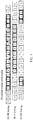
- FIG. 6 is a timing relationship diagram of uplink data according to this embodiment.
- the timing of sending the uplink data by the ReNB is advanced by the specified time value of sending uplink data by the DeNB, and the specified time value is the propagation delay ( ⁇ t) between the DeNB and the ReNB.
- ⁇ t propagation delay
- the ReNB and the DeNB send uplink data at the same time
- timing of sending the uplink data by the ReNB is ⁇ t earlier than timing of sending the uplink data by the DeNB.
- the timing of receiving the uplink data by the ReNB is advanced, so that a last symbol 13 in a previous subframe of the ReNB is prevented from being interfered with by sending of uplink data by the RUE in a current subframe.
- the DeNB is used as a reference for the propagation delay between the DeNB and the ReNB, to delay the timing of receiving the downlink data by the ReNB to ensure that sending of the downlink data by the ReNB does not interfere with receiving of the downlink data by the RUE; and advance the timing of sending the uplink data by the ReNB to ensure that sending of the uplink data by the ReNB does not interfere with receiving of the uplink data by the RUE.
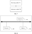
- FIG. 7 is a schematic structural diagram of an apparatus for reducing co-channel interference according to an embodiment of this application. As shown in FIG. 7 , the apparatus specifically includes:
- the adjustment module 702 is configured to: delay timing of receiving the downlink data by the ReNB by a specified time value of receiving downlink data by the DeNB, and advance timing of sending the uplink data by the ReNB by a specified time value of sending uplink data by the DeNB.
- the specified time value is the propagation delay.
- the propagation delay is determined in the following manner:
- the DeNB detects and receives an arrival time of a sounding reference signal SRS that is sent by user equipment UE to determine a timing advance TA value, and determines the propagation delay based on the TA value; or the DeNB determines the propagation delay based on a physical distance between the ReNB and relay UE.
- SRS sounding reference signal
- the apparatus for reducing co-channel interference in this embodiment may perform the method for reducing co-channel interference shown in FIG. 4 , and may perform all steps in the method shown in FIG. 4 , to achieve the technical effect of the method for reducing co-channel interference.
- the apparatus for reducing co-channel interference in this embodiment may perform the method for reducing co-channel interference shown in FIG. 4 , and may perform all steps in the method shown in FIG. 4 , to achieve the technical effect of the method for reducing co-channel interference.
- details are not described herein again.
- FIG. 8 is a schematic structural diagram of hardware of a base station according to an embodiment of this application. As shown in FIG. 8 , the base station specifically includes a transceiver 801, a processor 802, and a memory 803.
- the transceiver 801 may be an antenna.
- the processor 802 may be a central processing unit (central processing unit, CPU), or a combination of a CPU and a hardware chip.
- the hardware chip may be an application-specific integrated circuit (application-specific integrated circuit, ASIC), a programmable logic device (programmable logic device, PLD), or a combination thereof.
- the PLD may be a complex programmable logic device (complex programmable logic device, CPLD), a field programmable gate array (field-programmable gate array, FPGA), generic array logic (generic array logic, GAL), or a combination thereof.
- the memory 803 is configured to store various applications, an operating system, and data.
- the memory 803 may transmit stored data to the processor 802.
- the memory 803 may include a volatile memory, for example, a nonvolatile random access memory (nonvolatile random access memory, NVRAM), a phase-change random access memory (phase change RAM, PRAM), or a magnetoresistive random access memory (magnetoresistive RAM, MRAM).
- NVRAM nonvolatile random access memory
- PRAM phase change RAM
- MRAM magnetoresistive random access memory
- the memory 803 may further include a nonvolatile memory, for example, at least one magnetic disk storage device, an electrically erasable programmable read-only memory (electrically erasable programmable read-only memory, EEPROM), a flash memory device such as a NOR flash memory (NOR flash memory) or a NAND flash memory (NAND flash memory), or a semiconductor device such as a solid-state drive (solid state disk, SSD).
- NOR flash memory NOR flash memory
- NAND flash memory NAND flash memory
- SSD solid state disk
- the memory 803 may be integrated into the processor 802, or may exist independently.
- the transceiver 801 is configured to receive a propagation delay sent by a donor eNodeB DeNB, where the propagation delay is a delay of propagation between the DeNB and the ReNB.
- the processor 802 is configured to adjust, based on the propagation delay, timing parameters for sending uplink data and receiving downlink data by the ReNB, where the timing parameters are delays of the ReNB relative to the DeNB.
- the processor 802 is configured to: delay timing of receiving the downlink data by the ReNB by a specified time value of receiving downlink data by the DeNB, and advance timing of sending the uplink data by the ReNB by a specified time value of sending uplink data by the DeNB.
- the processor 802 is configured to configure that the specified time value is the propagation delay.
- the propagation delay is determined in the following manner:
- the DeNB detects and receives an arrival time of a sounding reference signal SRS that is sent by user equipment UE to determine a timing advance TA value, and determines the propagation delay based on the TA value; or the DeNB determines the propagation delay based on a physical distance between the ReNB and relay UE.
- SRS sounding reference signal
- the base station in this embodiment may perform the method for reducing co-channel interference shown in FIG. 4 , and may perform all steps in the method shown in FIG. 4 , to achieve the technical effect of the method for reducing co-channel interference.
- the base station in this embodiment may perform the method for reducing co-channel interference shown in FIG. 4 , and may perform all steps in the method shown in FIG. 4 , to achieve the technical effect of the method for reducing co-channel interference.
- the integrated unit When the integrated unit is implemented in the form of a software function unit and sold or used as an independent product, the integrated unit may be stored in a computer-readable storage medium. Based on such an understanding, all or a part of the technical solutions of this application may be implemented in a form of a software product.
- the computer software product is stored in a storage medium, and includes several instructions for instructing a computer device (which may be a personal computer, a server, a network device, or the like) to perform all or some of the steps of the methods described in the embodiments of this application.
- the foregoing storage medium includes any medium that can store program code, such as a flash drive, a removable hard disk, a read-only memory (English: read-only memory, ROM), a random access memory (English: random access memory, RAM), a magnetic disk, or an optical disc.
- program code such as a flash drive, a removable hard disk, a read-only memory (English: read-only memory, ROM), a random access memory (English: random access memory, RAM), a magnetic disk, or an optical disc.
Landscapes
- Engineering & Computer Science (AREA)
- Computer Networks & Wireless Communication (AREA)
- Signal Processing (AREA)
- Mobile Radio Communication Systems (AREA)
Applications Claiming Priority (1)
| Application Number | Priority Date | Filing Date | Title |
|---|---|---|---|
| PCT/CN2018/098941 WO2020029005A1 (zh) | 2018-08-06 | 2018-08-06 | 一种减小同频干扰的方法、装置及基站 |
Publications (2)
| Publication Number | Publication Date |
|---|---|
| EP3823367A1 true EP3823367A1 (de) | 2021-05-19 |
| EP3823367A4 EP3823367A4 (de) | 2021-07-28 |
Family
ID=69413942
Family Applications (1)
| Application Number | Title | Priority Date | Filing Date |
|---|---|---|---|
| EP18929490.3A Pending EP3823367A4 (de) | 2018-08-06 | 2018-08-06 | Verfahren und vorrichtung zur reduzierung von gleichkanalinterferenzen und basisstation |
Country Status (4)
| Country | Link |
|---|---|
| US (1) | US11533696B2 (de) |
| EP (1) | EP3823367A4 (de) |
| CN (1) | CN112514467B (de) |
| WO (1) | WO2020029005A1 (de) |
Family Cites Families (20)
| Publication number | Priority date | Publication date | Assignee | Title |
|---|---|---|---|---|
| CN101262691B (zh) * | 2007-03-09 | 2012-07-25 | 电信科学技术研究院 | 支持中继的蜂窝系统避免上下行干扰的实现方法及装置 |
| CN102217352B (zh) * | 2008-11-18 | 2016-04-20 | 诺基亚技术有限公司 | 在通信系统中进行中继 |
| CN101932037B (zh) * | 2009-06-19 | 2014-07-02 | 中兴通讯股份有限公司 | 保证业务承载传输时延的方法与装置 |
| CN102036382B (zh) * | 2009-09-30 | 2014-09-03 | 华为技术有限公司 | 一种无线资源配置方法、系统和装置 |
| WO2011043636A2 (ko) * | 2009-10-09 | 2011-04-14 | 엘지전자 주식회사 | 무선 통신 시스템에서 상향링크 백홀 신호를 송신 및 수신을 위한 장치 및 그 방법 |
| US9030977B2 (en) * | 2009-10-15 | 2015-05-12 | Qualcomm Incorporated | Methods and apparatus for transport block size determination |
| US8576755B2 (en) * | 2010-01-11 | 2013-11-05 | Qualcomm Incorporated | Apparatus and method for relay transition time |
| EP2378703A1 (de) * | 2010-04-13 | 2011-10-19 | Panasonic Corporation | Umsetzung von Steuerinformationen zur Steuerung von Kanalelementen |
| CN102291815B (zh) * | 2010-06-21 | 2015-07-22 | 中兴通讯股份有限公司 | 一种中继网络的定时配置方法及系统 |
| GB2491336B (en) * | 2011-03-24 | 2015-12-16 | Nvidia Corp | Mobile radio network, relay node and method |
| US20120252355A1 (en) * | 2011-04-04 | 2012-10-04 | Qualcomm Incorporated | Apparatus and method for handing over relays |
| EP3240326B1 (de) * | 2011-08-15 | 2019-11-27 | Telefonaktiebolaget LM Ericsson (publ) | Verfahren und knoten zur handhabung von messungen in einem drahtloskommunikationssystem |
| EP2639989A1 (de) * | 2012-03-16 | 2013-09-18 | Panasonic Corporation | Suchraum für ePDCCH-Steuerungsinformationen in einem OFDM-basierten mobilen Kommunikationssystem |
| US9814073B2 (en) * | 2013-01-30 | 2017-11-07 | Qualcomm Incorporated | PRACH-based proximity detection |
| CN104185186B (zh) * | 2013-05-23 | 2018-02-23 | 华为技术有限公司 | 信号干扰的抑制方法及网络设备 |
| EP3598656B1 (de) * | 2013-10-18 | 2021-07-21 | QUALCOMM Incorporated | Verfahren und vorrichtung zur konfiguration von csi-rs für 3-d-mimo |
| US9516520B2 (en) * | 2013-10-30 | 2016-12-06 | Qualcomm Incorporated | Enabling coexistence of differently-capable user equipment |
| US10149201B2 (en) * | 2015-01-30 | 2018-12-04 | Telefonaktiebolaget Lm Ericsson (Publ) | Method and network node for transmission coordination on wireless backhaul path |
| US10462724B2 (en) * | 2015-06-09 | 2019-10-29 | Qualcomm Incorporated | Method and apparatus for minimizing/avoiding conflicts between different radio access technologies serving user equipment |
| WO2018189726A1 (en) * | 2017-04-13 | 2018-10-18 | Telefonaktiebolaget Lm Ericsson (Publ) | Distributed scheduling algorithm for cpri over ethernet |
-
2018
- 2018-08-06 EP EP18929490.3A patent/EP3823367A4/de active Pending
- 2018-08-06 CN CN201880096156.0A patent/CN112514467B/zh active Active
- 2018-08-06 WO PCT/CN2018/098941 patent/WO2020029005A1/zh not_active Ceased
-
2021
- 2021-02-06 US US17/169,407 patent/US11533696B2/en active Active
Also Published As
| Publication number | Publication date |
|---|---|
| CN112514467A (zh) | 2021-03-16 |
| EP3823367A4 (de) | 2021-07-28 |
| CN112514467B (zh) | 2022-09-23 |
| US20210160806A1 (en) | 2021-05-27 |
| US11533696B2 (en) | 2022-12-20 |
| WO2020029005A1 (zh) | 2020-02-13 |
Similar Documents
| Publication | Publication Date | Title |
|---|---|---|
| EP3737169B1 (de) | Timing-verfahren und -vorrichtung | |
| US12213215B2 (en) | User equipment overheating handling during LTE-new radio simultaneous UL transmission | |
| CN110972307B (zh) | 新无线电的交叉时隙调度 | |
| CN109565719B (zh) | 用于主小区改变的方法、设备和计算机程序 | |
| US20150223184A1 (en) | Timing Advance Timer Start for Uplink Transmissions | |
| EP3032896A1 (de) | Zeitvorlaufsverfahren und vorrichtungen | |
| JP7079276B2 (ja) | 端末、無線通信システム及び通信方法 | |
| US12133211B2 (en) | Base station and user equipment for time division duplexing configuration deconfliction | |
| CN108616976B (zh) | 通信方法、接入网设备和终端 | |
| CN112106399A (zh) | 用于确定测量间隙的方法、设备和计算机可读介质 | |
| AU2017439929A1 (en) | Method for determining non-contention random access resource, network device and terminal device | |
| US11202322B2 (en) | Random access method and terminal device | |
| US11533696B2 (en) | Method and apparatus for reducing co-channel interference, and base station | |
| JPWO2019220650A1 (ja) | ユーザ装置及び基地局装置 | |
| WO2013050083A1 (en) | Determination of transmission timing information after activation of a cell | |
| JP6992173B2 (ja) | 送信方法、端末デバイス、およびネットワークデバイス | |
| TW202433974A (zh) | 用於多傳輸接收點之功率控制技術 | |
| WO2024216437A1 (zh) | 通信方法、通信装置、计算机可读存储介质和程序产品 | |
| CN115868118A (zh) | 用于支持免许可频带中的时间敏感通信的空间重用的功率控制 | |
| WO2024169128A1 (en) | Systems and methods for timing for smart nodes |
Legal Events
| Date | Code | Title | Description |
|---|---|---|---|
| STAA | Information on the status of an ep patent application or granted ep patent |
Free format text: STATUS: THE INTERNATIONAL PUBLICATION HAS BEEN MADE |
|
| PUAI | Public reference made under article 153(3) epc to a published international application that has entered the european phase |
Free format text: ORIGINAL CODE: 0009012 |
|
| STAA | Information on the status of an ep patent application or granted ep patent |
Free format text: STATUS: REQUEST FOR EXAMINATION WAS MADE |
|
| 17P | Request for examination filed |
Effective date: 20210215 |
|
| AK | Designated contracting states |
Kind code of ref document: A1 Designated state(s): AL AT BE BG CH CY CZ DE DK EE ES FI FR GB GR HR HU IE IS IT LI LT LU LV MC MK MT NL NO PL PT RO RS SE SI SK SM TR |
|
| A4 | Supplementary search report drawn up and despatched |
Effective date: 20210629 |
|
| RIC1 | Information provided on ipc code assigned before grant |
Ipc: H04W 56/00 20090101AFI20210623BHEP |
|
| DAV | Request for validation of the european patent (deleted) | ||
| DAX | Request for extension of the european patent (deleted) | ||
| STAA | Information on the status of an ep patent application or granted ep patent |
Free format text: STATUS: EXAMINATION IS IN PROGRESS |
|
| 17Q | First examination report despatched |
Effective date: 20230803 |