EP3822660A1 - Integrity detection system for an ultrasound transducer - Google Patents
Integrity detection system for an ultrasound transducer Download PDFInfo
- Publication number
- EP3822660A1 EP3822660A1 EP19208991.0A EP19208991A EP3822660A1 EP 3822660 A1 EP3822660 A1 EP 3822660A1 EP 19208991 A EP19208991 A EP 19208991A EP 3822660 A1 EP3822660 A1 EP 3822660A1
- Authority
- EP
- European Patent Office
- Prior art keywords
- ultrasound
- signal
- processing unit
- signal processing
- vessel
- Prior art date
- Legal status (The legal status is an assumption and is not a legal conclusion. Google has not performed a legal analysis and makes no representation as to the accuracy of the status listed.)
- Pending
Links
- 238000002604 ultrasonography Methods 0.000 title claims abstract description 177
- 238000001514 detection method Methods 0.000 title claims abstract description 25
- 238000012360 testing method Methods 0.000 claims abstract description 73
- 238000012545 processing Methods 0.000 claims abstract description 64
- 230000008878 coupling Effects 0.000 claims abstract description 47
- 238000010168 coupling process Methods 0.000 claims abstract description 47
- 238000005859 coupling reaction Methods 0.000 claims abstract description 47
- 230000005284 excitation Effects 0.000 claims description 43
- 238000000034 method Methods 0.000 claims description 31
- 230000008569 process Effects 0.000 claims description 7
- 238000001914 filtration Methods 0.000 claims description 3
- 238000013473 artificial intelligence Methods 0.000 claims description 2
- 238000003909 pattern recognition Methods 0.000 claims description 2
- 230000003595 spectral effect Effects 0.000 claims description 2
- 238000001228 spectrum Methods 0.000 claims description 2
- 230000002123 temporal effect Effects 0.000 claims description 2
- 238000010586 diagram Methods 0.000 description 12
- 238000005259 measurement Methods 0.000 description 9
- 238000004590 computer program Methods 0.000 description 5
- 238000004458 analytical method Methods 0.000 description 4
- 230000006870 function Effects 0.000 description 4
- 238000009736 wetting Methods 0.000 description 3
- 230000008901 benefit Effects 0.000 description 2
- 230000007423 decrease Effects 0.000 description 2
- 230000001419 dependent effect Effects 0.000 description 2
- 238000012544 monitoring process Methods 0.000 description 2
- 238000012546 transfer Methods 0.000 description 2
- 235000019687 Lamb Nutrition 0.000 description 1
- 230000008859 change Effects 0.000 description 1
- 238000012512 characterization method Methods 0.000 description 1
- 238000004891 communication Methods 0.000 description 1
- 238000013500 data storage Methods 0.000 description 1
- 230000002950 deficient Effects 0.000 description 1
- 238000003745 diagnosis Methods 0.000 description 1
- 238000009434 installation Methods 0.000 description 1
- 238000011835 investigation Methods 0.000 description 1
- 239000007788 liquid Substances 0.000 description 1
- 230000003287 optical effect Effects 0.000 description 1
- 238000007781 pre-processing Methods 0.000 description 1
- 230000001902 propagating effect Effects 0.000 description 1
- 230000002441 reversible effect Effects 0.000 description 1
- 230000002195 synergetic effect Effects 0.000 description 1
Images


Classifications
-
- G—PHYSICS
- G01—MEASURING; TESTING
- G01S—RADIO DIRECTION-FINDING; RADIO NAVIGATION; DETERMINING DISTANCE OR VELOCITY BY USE OF RADIO WAVES; LOCATING OR PRESENCE-DETECTING BY USE OF THE REFLECTION OR RERADIATION OF RADIO WAVES; ANALOGOUS ARRANGEMENTS USING OTHER WAVES
- G01S7/00—Details of systems according to groups G01S13/00, G01S15/00, G01S17/00
- G01S7/52—Details of systems according to groups G01S13/00, G01S15/00, G01S17/00 of systems according to group G01S15/00
- G01S7/52004—Means for monitoring or calibrating
-
- G—PHYSICS
- G01—MEASURING; TESTING
- G01N—INVESTIGATING OR ANALYSING MATERIALS BY DETERMINING THEIR CHEMICAL OR PHYSICAL PROPERTIES
- G01N29/00—Investigating or analysing materials by the use of ultrasonic, sonic or infrasonic waves; Visualisation of the interior of objects by transmitting ultrasonic or sonic waves through the object
- G01N29/04—Analysing solids
- G01N29/041—Analysing solids on the surface of the material, e.g. using Lamb, Rayleigh or shear waves
-
- G—PHYSICS
- G01—MEASURING; TESTING
- G01N—INVESTIGATING OR ANALYSING MATERIALS BY DETERMINING THEIR CHEMICAL OR PHYSICAL PROPERTIES
- G01N29/00—Investigating or analysing materials by the use of ultrasonic, sonic or infrasonic waves; Visualisation of the interior of objects by transmitting ultrasonic or sonic waves through the object
- G01N29/22—Details, e.g. general constructional or apparatus details
- G01N29/28—Details, e.g. general constructional or apparatus details providing acoustic coupling, e.g. water
-
- G—PHYSICS
- G01—MEASURING; TESTING
- G01N—INVESTIGATING OR ANALYSING MATERIALS BY DETERMINING THEIR CHEMICAL OR PHYSICAL PROPERTIES
- G01N29/00—Investigating or analysing materials by the use of ultrasonic, sonic or infrasonic waves; Visualisation of the interior of objects by transmitting ultrasonic or sonic waves through the object
- G01N29/04—Analysing solids
- G01N29/07—Analysing solids by measuring propagation velocity or propagation time of acoustic waves
-
- G—PHYSICS
- G01—MEASURING; TESTING
- G01N—INVESTIGATING OR ANALYSING MATERIALS BY DETERMINING THEIR CHEMICAL OR PHYSICAL PROPERTIES
- G01N29/00—Investigating or analysing materials by the use of ultrasonic, sonic or infrasonic waves; Visualisation of the interior of objects by transmitting ultrasonic or sonic waves through the object
- G01N29/04—Analysing solids
- G01N29/11—Analysing solids by measuring attenuation of acoustic waves
-
- G—PHYSICS
- G01—MEASURING; TESTING
- G01N—INVESTIGATING OR ANALYSING MATERIALS BY DETERMINING THEIR CHEMICAL OR PHYSICAL PROPERTIES
- G01N29/00—Investigating or analysing materials by the use of ultrasonic, sonic or infrasonic waves; Visualisation of the interior of objects by transmitting ultrasonic or sonic waves through the object
- G01N29/22—Details, e.g. general constructional or apparatus details
- G01N29/30—Arrangements for calibrating or comparing, e.g. with standard objects
-
- G—PHYSICS
- G01—MEASURING; TESTING
- G01N—INVESTIGATING OR ANALYSING MATERIALS BY DETERMINING THEIR CHEMICAL OR PHYSICAL PROPERTIES
- G01N29/00—Investigating or analysing materials by the use of ultrasonic, sonic or infrasonic waves; Visualisation of the interior of objects by transmitting ultrasonic or sonic waves through the object
- G01N29/44—Processing the detected response signal, e.g. electronic circuits specially adapted therefor
- G01N29/4409—Processing the detected response signal, e.g. electronic circuits specially adapted therefor by comparison
- G01N29/4427—Processing the detected response signal, e.g. electronic circuits specially adapted therefor by comparison with stored values, e.g. threshold values
-
- G—PHYSICS
- G01—MEASURING; TESTING
- G01N—INVESTIGATING OR ANALYSING MATERIALS BY DETERMINING THEIR CHEMICAL OR PHYSICAL PROPERTIES
- G01N29/00—Investigating or analysing materials by the use of ultrasonic, sonic or infrasonic waves; Visualisation of the interior of objects by transmitting ultrasonic or sonic waves through the object
- G01N29/44—Processing the detected response signal, e.g. electronic circuits specially adapted therefor
- G01N29/4409—Processing the detected response signal, e.g. electronic circuits specially adapted therefor by comparison
- G01N29/4436—Processing the detected response signal, e.g. electronic circuits specially adapted therefor by comparison with a reference signal
-
- G—PHYSICS
- G01—MEASURING; TESTING
- G01N—INVESTIGATING OR ANALYSING MATERIALS BY DETERMINING THEIR CHEMICAL OR PHYSICAL PROPERTIES
- G01N29/00—Investigating or analysing materials by the use of ultrasonic, sonic or infrasonic waves; Visualisation of the interior of objects by transmitting ultrasonic or sonic waves through the object
- G01N29/44—Processing the detected response signal, e.g. electronic circuits specially adapted therefor
- G01N29/4463—Signal correction, e.g. distance amplitude correction [DAC], distance gain size [DGS], noise filtering
-
- G—PHYSICS
- G01—MEASURING; TESTING
- G01N—INVESTIGATING OR ANALYSING MATERIALS BY DETERMINING THEIR CHEMICAL OR PHYSICAL PROPERTIES
- G01N29/00—Investigating or analysing materials by the use of ultrasonic, sonic or infrasonic waves; Visualisation of the interior of objects by transmitting ultrasonic or sonic waves through the object
- G01N29/44—Processing the detected response signal, e.g. electronic circuits specially adapted therefor
- G01N29/46—Processing the detected response signal, e.g. electronic circuits specially adapted therefor by spectral analysis, e.g. Fourier analysis or wavelet analysis
-
- G—PHYSICS
- G01—MEASURING; TESTING
- G01N—INVESTIGATING OR ANALYSING MATERIALS BY DETERMINING THEIR CHEMICAL OR PHYSICAL PROPERTIES
- G01N2291/00—Indexing codes associated with group G01N29/00
- G01N2291/01—Indexing codes associated with the measuring variable
- G01N2291/011—Velocity or travel time
-
- G—PHYSICS
- G01—MEASURING; TESTING
- G01N—INVESTIGATING OR ANALYSING MATERIALS BY DETERMINING THEIR CHEMICAL OR PHYSICAL PROPERTIES
- G01N2291/00—Indexing codes associated with group G01N29/00
- G01N2291/04—Wave modes and trajectories
- G01N2291/044—Internal reflections (echoes), e.g. on walls or defects
-
- G—PHYSICS
- G01—MEASURING; TESTING
- G01N—INVESTIGATING OR ANALYSING MATERIALS BY DETERMINING THEIR CHEMICAL OR PHYSICAL PROPERTIES
- G01N2291/00—Indexing codes associated with group G01N29/00
- G01N2291/10—Number of transducers
- G01N2291/105—Number of transducers two or more emitters, two or more receivers
-
- G—PHYSICS
- G01—MEASURING; TESTING
- G01N—INVESTIGATING OR ANALYSING MATERIALS BY DETERMINING THEIR CHEMICAL OR PHYSICAL PROPERTIES
- G01N2291/00—Indexing codes associated with group G01N29/00
- G01N2291/26—Scanned objects
- G01N2291/263—Surfaces
- G01N2291/2634—Surfaces cylindrical from outside
Definitions
- the present invention relates to an integrity detection system for detecting the integrity status of an acoustic coupling between an ultrasound transducer and a wall of a vessel, a method for detecting the integrity of an acoustic coupling, a signal processing unit, a program element, and a computer readable medium
- Non-invasive ultrasonic sensors are usually mounted outside a vessel and generate acoustic waves, which penetrate through the wall.
- the propagation of the waves is influenced by the properties of the vessel content, including, for example, level or flow.
- characterization of the waves outside the vessel after propagation allows the measurement of content properties.
- efficient, stable and reliable coupling of the acoustic waves in and out of the vessel is of key importance - especially for mobile or diagnostic applications.
- the objective of the invention is to detect the integrity status of an ultrasound transducer coupling of an ultrasound transducer attached to a wall of a vessel.
- the described embodiments similarly pertain to the integrity detection system for detecting the integrity status of an acoustic coupling between an ultrasound transducer and a wall of a vessel, the method for detecting the integrity status, the signal processing unit, the program element, and the computer readable medium. Synergetic effects may arise from different combinations of the embodiments although they might not be described in detail.
- an integrity detection system for detecting an integrity status of an acoustic coupling between an ultrasound transducer and a wall of a vessel.
- the integrity detection system comprises a first ultrasound transducer attached to a wall of the vessel and a signal processing unit.
- the first ultrasound transducer comprises a first ultrasound emitter and a first ultrasound receiver.
- the first ultrasound emitter is configured to emit a first ultrasound test signal.
- the at least one ultrasound receiver is configured to receive the first ultrasound test signal, and to transmit the received first ultrasound test signal or a signal corresponding to the received second ultrasound test signal, respectively, to the signal processing unit.
- the signal processing unit is configured to detect a first time of flight of the received first ultrasound test signal and to determine that the acoustic coupling between the first ultrasound emitter and the wall of the vessel is intact, if the detected first time of flight corresponds to the length of the path in the wall of the vessel from the first ultrasound emitter to the at least one ultrasound receiver.
- the first ultrasound emitter there may be one emitter and additionally one or more ultrasound receivers, which receive the first test signal emitted by the first ultrasound emitter.
- the receivers transmit the first test signal to the signal processing unit where the signal is analyzed for significances as, for example, peaks that are characteristic for the covered path. If the second test signal is not detected, the integrity is not given. That is, the contact for introducing the ultrasound energy into the wall and into the vessel, is not present.
- redundancy is provided, so that a decision whether the integrity is given or not may be made according to a policy regarding the amount of detected signals.
- the first test signal may be a dedicated test signal used only for the tests as described in this disclosure, or it may be emitted and used for a regular ultrasound measurement. In any case, the test signal is received and analyzed for an integrity check.
- one of the at least one ultrasound receivers is the first ultrasound emitter.
- the sound pulse is expected to make one or several round trips along the perimeter of vessel and couple back in the transducer.
- the time of flight or equivalently, the expected time of arrival (ToA) can be estimated from the circumference of the vessel and the speed of sound in the wall.
- a reference measurement may be performed, for example after a successful installation, to obtain the time of flight of one round trip.
- no signals can be detected around the expected ToA, or with the expected time of flight, respectively.
- the integrity detection system thus allows for detecting the integrity by checking, whether an emitted ultrasound signal is arriving after travelling circumferential around the vessel wall.
- the length of the path may comprise one round trip or several round trips around the vessel.
- the vessel is supposed to be cylindrical. However, the vessel may have another geometrical shape, where the signal may be reflected at the wall, edges, etc.
- first signal is used here for a set of single signals from the first ultrasound transducer, wherein each of the single signals may be emitted with a different mode.
- the transducer may be equipped with one or several emitter elements that can be operated at different frequencies, allowing the generation of different acoustic modes in the wall.
- the modes of the waves include, e.g. Lamb-, Rayleigh- or Scholte-waves.
- ultrasound transducer is used in this disclosure as an ultrasound device that includes a receive element ("receiver") and an emit element ("element").
- An “ultrasound receiver” may be a either integrated in an ultrasound transducer as, for example, the first ultrasound transducer, or a ultrasound device which is receiving only.
- the integrity detection system comprises a further ultrasound transducer configured to emit a second ultrasound test signal in the wall of the vessel along a path to the first ultrasound receiver and along a path to the further ultrasound transducer.
- the first ultrasound receiver and the further ultrasound transducer are configured to receive the second ultrasound test signal and to transmit the received second ultrasound test signal or a signal corresponding to the additionally received second ultrasound test signal, respectively, to the signal processing unit.
- the signal processing unit is further configured to detect second times of flight of the received second ultrasound test signal and to determine that the acoustic coupling of the first ultrasound transducer and the further ultrasound transducer is intact, if the detected second times of flight correspond to the corresponding lengths of the paths of the second signal.
- the second signal may be emitted independently, especially with respect to the emission time, from the second ultrasound signal. It is noted again, that the time of flight is equivalent to an expected ToA, as known to a skilled person.
- one or several transducers capable of emitting and receiving test signals are attached to the vessel wall. Any emit - receive configuration between the transducers is possible, allowing for further redundancy. Especially, it may happen, that the transducers aimed at testing the integrity of the acoustic coupling of the first transducer, have an insufficient contact for emitting or receiving the test signal.
- An arrangement with one or several transducers, each of which emits and receives a test signal, is capable to minimize the risk of false decisions.
- the at least one ultrasound receiver is further configured to measure an excitation signal of the first ultrasound test signal, and to transmit the received excitation signal to the signal processing unit.
- the signal processing unit is further configured to receive the excitation signal from the at least one ultrasound receiver, to determine the decay time of the received excitation signal, and to determine that the acoustic coupling of the first ultrasound emitter and the at least one ultrasound receiver is intact, if the decay time is less than a pre-determined threshold.
- the signal processing unit is further configured to detect the first time of flight, and to determine that the acoustic coupling between the first ultrasound emitter and the wall of the vessel is intact based on the first time of flight, if the signal processing unit has determined, that the acoustic coupling of the first ultrasound emitter and the at least one ultrasound receiver is not intact.
- the second test is performed.
- the second test may also be performed stand-alone, however, the first test is the easier to perform, and there is a chance that the second test might be omitted (in case the first test passes).
- the first signal for (i) the excitation measurement and for (ii) the measurement of the time of flight may be the same emitted signal, or two subsequent signals, where the order in which these signals are emitted, may be first (i) and thereafter (ii) or reverse.
- the signal (ii) is emitted only if the integrity check based on the excitation failed.
- the excitation signal is a signal generated by an application of an excitation voltage of the piezo for the first ultrasound test signal.
- the received excitation signal decreases in terms of amplitude as, for example, voltage or signal-to-noise ratio, with time in / after the excitation phase.
- the term "decay time” relates to the time from a starting time, for example, when the excitation of the piezo is started to the point of time, when, e.g., a pre-defined voltage or signal-to-noise ratio is reached during the de-excitation phase.
- the decay time may be characterized by the time parameter of the exponential curve, which may also be designated as "decay rate".
- the acoustic excitation process includes applying a voltage of several Volts at a certain operating frequency to the piezo, which then begins to oscillate with the operating frequency and emits an ultrasound signal.
- a couplant between the piezo and the vessel wall improves significantly the energy transfer from the piezo to the vessel wall or through the medium into the medium.
- the energy transfer into the medium is improved if the inner vessel wall is wet. Therefore, depending on the contact at the outer side and the wetting of the inner side, the energy is reflected more or less, which results in the described signal. If most of the energy is reflected due to an insufficient contact or wetting, the decay time is significantly longer than otherwise. Indeed, there is an overlapping of the excitation and reflecting signal.
- the decay of the signal including the echo signal is regarded as being a part of the acoustic excitation process in this disclosure. Therefore, the term "excitation signal" comprises also the echo signal.
- the decay time may be compared to a factory-calibrated value.
- factory-calibrated waveform templates that are representative for the acoustically terminated and unterminated transducer can be stored in the signal processing unit, which are subtracted from or cross-correlated with the measured waveform for comparison.
- Acoustic terminated means that the soundwaves are absorbed at the termination, so that there are no reflections back to the piezo, resulting in a fast ring down time, contrary to the unterminated case.
- the system therefore allows an online diagnosis of the integrity of the acoustic coupling for ultrasonic sensors by measuring the decay time or decay rate, respectively, of the acoustic excitation signal or further comparison methods, and the presence of acoustic signals that propagate along the circumference of a vessel. Besides decay time and rate, other quantities that characterize the change of the excitation signal can be similarly used, some of which are described below.
- a single transducer with a single excitation element is suitable to perform the integrity check, even during normal transducer operation, for example, during a non-invasive level or flow measurement, and provides continuous validity information on the measured data. This self-diagnostic feature improves sensor reliability and enables condition monitoring, which is a key function of smart digital sensors.
- the excitation signal transmitted to the signal processing unit is a raw signal
- the signal processing unit is configured to pre-process the raw signal by applying a Hilbert transform and/or frequency filtering.
- a raw signal is the analog signal as received, a suitably amplified (or electrically pre-processed, e.g. using analog filters) raw signal, or more sophisticated, the digitally sampled signal.
- the signal processing unit is further configured to subtract the raw signal or the pre-processed signal from factory-calibrated waveform templates and/or to cross-correlate the raw signal with factory-calibrated waveform templates, wherein the factory-calibrated waveform templates are representative for an acoustically terminated and an acoustically unterminated transducer.
- the signal processing unit may be further configured to determine, whether the acoustic coupling of the first ultrasound transducer is intact, based on the subtraction and/or the cross-correlation.
- the factory-calibrated waveform templates may be stored in a memory of the signal processing unit.
- the templates may be stored as samples or processed samples depending on the type of comparison to be performed with the measured signal.
- the threshold used to differentiate between intact and defective acoustic coupling is a signal-to-noise-ratio or a value based on the output of an artificial intelligence algorithm or a pattern recognition algorithm.
- a reference-signal-to-noise-ratio may be pre-defined to which the measured signal-to-noise-ratio is compared.
- the signal processing unit is further configured to compare an amplitude, a power spectrum, a spectral and/or a temporal phase of the received excitation signal with the waveform templates.
- different further characteristics of the sound wave may be used for the comparison of the reference waveforms with the measured waveform of the excitation signal.
- a method for detecting an integrity status of an acoustic coupling between an ultrasound transducer and a wall of a vessel comprises the following steps: In a first step, a first ultrasound test signal, is emitted by a first ultrasound emitter. In a next step, the first ultrasound test signal is received by at least one ultrasound receiver and transmitted to the signal processing unit. In a further step, a time of flight of the received first ultrasound test signal is detected by the signal processing unit.
- acoustic coupling between the first ultrasound transducer and the wall of the vessel of the first ultrasound transducer is intact, if the detected time of flight corresponds to the length of a path in the wall of the vessel from the first ultrasound emitter to the at least one ultrasound receiver.
- the steps described in the method may also be part of a more extensive method corresponding to the above description of the system, in which first the decay time of the excitation signal is analyzed, and, if the integrity could not be determined by the analysis, the steps described above may be performed as a second check.
- the method comprises further the following steps: Measuring an excitation signal of the first ultrasound test signal, and transmitting the received excitation signal to the signal processing unit. Determining, by the signal processing unit, the decay time of the received excitation. determining, by the signal processing unit, that the acoustic coupling of the first ultrasound emitter and the at least one ultrasound receiver is intact, if the decay time is less than a pre-determined threshold, and detecting the first time of flight and determining that the acoustic coupling between the first ultrasound emitter and the wall of the vessel is intact based on the first time of flight, if the signal processing unit has determined, that the acoustic coupling of the first ultrasound emitter and the at least one ultrasound receiver is not intact.
- a method for monitoring the integrity of acoustic coupling of ultrasonic transducers may comprise one or two parts.
- the decay rate of an acoustic excitation pulse is measured at the operational frequency. If the decay time is comparable to that corresponding to the acoustically terminated transducer, the acoustic contact is considered to be present. If the decay time is longer, in the second part of the method, a second measurement may be performed. The second part of the method may be performed as stand-alone-test, i.e., without executing the first part.
- acoustic modes are launched that are propagating in the vessel wall and propagate along a path such that the acoustic signal is detected by the same transducer as the corresponding emitting transducer. If the pulse(s) is (are) present at the expected time(s), the acoustic contact is considered to be appropriate.
- the expected pulse propagation times can be estimated from the known speed of sound for the corresponding acoustic modes and the length of the propagation path. In case the pulse is absent, the acoustic contact is lost and a warning information may be generated for the user or the measurement may be marked as invalid.
- a signal processing unit configured to cause a first ultrasound emitter to emit a first ultrasound test signal, to receive, from at least one ultrasound receiver the first ultrasound test signal, to detect the time of flight of the received first ultrasound test signal, and to determine that the acoustic coupling of the first ultrasound emitter and the at least one ultrasound receiver to the wall of the vessel is intact, if the detected time of flight corresponds to the length of a path in the wall of the vessel from the first ultrasound emitter to the at least one ultrasound receiver.
- the signal processing unit may comprise circuits without programmable logics or may be or comprise a micro controller, a field programmable gate array (FPGA), an ASIC, a Complex Programmable Logic Devices (CPLD), or any other programmable logic devices known to person skilled in the art.
- the signal processing unit may further comprise communication devices for receiving data from the sensors by wire or over the air, for sending signals to the sensors, and optionally for communicating with network devices.
- the signal processing unit may comprise a storage for storing code and data, as for example the soundwave templates of a terminated and an unterminated transducer.
- the signal processing unit may be a single device inside an enclosure or a logical device consisting of several locally distributed hardware devices.
- a program element which when being executed on a processor of the signal processing unit, controls an integrity detection system to perform the steps of the method.
- the computer program element may be part of a computer program, but it can also be an entire program by itself.
- the computer program element may be used to update an already existing computer program to get to the present invention.
- a computer readable medium on which a program element is stored.
- the computer readable medium may be seen as a storage medium, such as for example, a USB stick, a CD, a DVD, a data storage device, a hard disk, or any other medium on which a program element as described above can be stored.
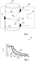
- Fig. 1 shows a diagram of a first example of an integrity detection system 100 for detecting the integrity status of an acoustic coupling between an ultrasound transducer and a wall of a vessel 102.
- Transducer 110 is a transducer for emitting and receiving ultrasound signals, whilst devices 112 and 114 are ultrasound receivers.
- Transducer 110 emits ultrasound signals using different acoustic modes, resulting in propagation paths 122 inside the wall of the vessel 102 from the transducer 110 to receiver 112, and similarly, path 124 to receiver 124 and 120 which runs around the vessel 102 so that the transducer 110 receives the signal emitted by itself.
- the expected time of flight can be calculated and compared to the measured time difference between emitting and receiving. Further indicators may be used without measuring the time of flight. For example, if a signal is detected at receivers 112 and 114 at - depending on the geometry - the same time, an intact coupling can be assumed. Furthermore, a regular repetition of a received signal, i.e., significant peaks of the amplitude as shown in Fig. 4a , corresponding to the round-trips of the test signal around the vessel 102 indicate a proper connection.
- Fig. 2 shows a diagram of a second example of an integrity detection system.
- the first transducer 110 and two further transducers 212, 214 are attached to the wall of the vessel 102.
- the first transducer 110 emits a first test signal to the further transducers 212, 214, and receives a second signal from each of the further transducers 212, 214, as indicated by arrows 222 and 224.
- the first transducer 110 emits the first signal to itself as indicated by arrow 220.
- transducers 212 and 214 emit each a signal to themselves 232, 234, and to each other 226.
- Fig. 3 shows a diagram of the measured ring down of the signal of the excitation test signal.
- the thin lines show the envelope of the ultrasound signal obtained e.g. by applying a Hilbert transform and frequency filtering from the raw signal of the signal including the echo signal.
- the thick lines 302, 304 are a fit of an exponential decay of the envelope signal.
- the straight line at the beginning is caused by the saturation of the piezo during the excitation phase when a high initial voltage is applied to the piezo, or when the amplitude is still too high immediately after this phase.
- Line 304 is the result for a signal, when there is a good contact and the vessel wall is wet inside at the transducer position, whereas line 302 shows the case when there is no liquid in the vessel 102 at this position or there is no contact.
- a decay constant of the exponential function may be determined representing the decay rate, which may be compared to pre-determined decay constants or decay rates, respectively, of the exponential functions when the wall inside the vessel is wet or dry, or when a contact between the piezo and the vessel wall is present or not.
- Fig. 4a shows an exemplary diagram of an envelope of the received voltage u [mV] of round-trip signal versus time t [ ⁇ s], and Fig. 4b shows the top view of the corresponding arrangement with a transducer attached to a vessel 102.
- the test signal in Fig. 4a is an A0 acoustic mode signal at an operation frequency of 380 kHz (a Lamb wave), which travelled around the vessel 102.
- Fig. 4b shows a top view on the vessel 102 and the emitting and receiving transducer 110.
- the arrows 430, and 432 indicate the path of the ultrasound test signal around the vessel.
- the first received peak 402 is the excitation signal including the echo signal echoed at the vessel wall immediately after emitting the signal.
- Peak 404 is the detected signal after running once around the vessel. Accordingly, peaks 206 and 208 are the peaks of the second and third arrival of the signal, e.g. due to round trips or reflections.
- Fig. 5 shows a flow diagram of a method according to an embodiment.
- the method 500 for detecting the integrity of the acoustic coupling of an ultrasound transducer at a wall of a vessel comprising the steps: Emitting 502, by the ultrasound emitter, a second ultrasound test signal.
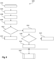
- Fig. 6 shows a further flow diagram 600 according to an example.
- a first test signal is emitted 604 by an ultrasound transducer 110.
- the first test signal may be the same test signal as described for Fig. 5 , or a different signal.
- the first test signal is received as an excitation signal by the ultrasound transducer 110 and transmitted to a signal processing unit 150.
- the decay time of the received excitation signal is determined by the signal processing unit and analyzed with respect to the integrity of the acoustic coupling of the transducer.
- the analysis may comprise pre-processing the raw signal and an investigation of the delay time and characteristics of the waveform, which may be compared to stored waveform templates by subtraction or cross-correlation.
- the signal processing unit sends 612 a corresponding indication to, e.g. a human-man interface or another interface, and the process is terminated 630. Otherwise, in 616, the above described method 500 is performed. If in 618 the result of the analysis is, that the acoustic coupling is intact, the signal processing unit sends in 620 an indication, that the coupling is all right and the process is terminated 630. Otherwise it is indicated 624 that the coupling is not intact, and the process is terminated 630.
- a major portion of the acoustic energy is radiated into the medium contained by the vessel, which leads to a fast decay (acoustically terminated transducer).
- the signal decay is closer to that of an unterminated transducer, it may be caused either due to a) the loss of acoustic contact or b) changes of the wetting of the wall (caused, e.g. by low level or partial filling).
- a computer program may be stored/distributed on a suitable medium such as an optical storage medium or a solid-state medium supplied together with or as part of other hardware, but may also be distributed in other forms, such as via the Internet or other wired or wireless telecommunication systems. Any reference signs in the claims should not be construed as limiting the scope of the claims.
Abstract
Description
- The present invention relates to an integrity detection system for detecting the integrity status of an acoustic coupling between an ultrasound transducer and a wall of a vessel, a method for detecting the integrity of an acoustic coupling, a signal processing unit, a program element, and a computer readable medium
- Non-invasive ultrasonic sensors are usually mounted outside a vessel and generate acoustic waves, which penetrate through the wall. The propagation of the waves is influenced by the properties of the vessel content, including, for example, level or flow. Thus, characterization of the waves outside the vessel after propagation allows the measurement of content properties. For this, efficient, stable and reliable coupling of the acoustic waves in and out of the vessel is of key importance - especially for mobile or diagnostic applications.
- The objective of the invention is to detect the integrity status of an ultrasound transducer coupling of an ultrasound transducer attached to a wall of a vessel.
- The problem is solved by the subject-matter of the independent claims. Embodiments are provided by the dependent claims, the following description and the accompanying figures.
- The described embodiments similarly pertain to the integrity detection system for detecting the integrity status of an acoustic coupling between an ultrasound transducer and a wall of a vessel, the method for detecting the integrity status, the signal processing unit, the program element, and the computer readable medium. Synergetic effects may arise from different combinations of the embodiments although they might not be described in detail.
- Further on, it shall be noted that all embodiments of the present invention concerning a method, might be carried out with the order of the steps as described, nevertheless this has not to be the only and essential order of the steps of the method. The herein presented methods can be carried out with another order of the disclosed steps without departing from the respective method embodiment, unless explicitly mentioned to the contrary hereinafter.
- Technical terms are used by their common sense. If a specific meaning is conveyed to certain terms, definitions of terms will be given in the following in the context of which the terms are used.
- According to a first aspect, an integrity detection system for detecting an integrity status of an acoustic coupling between an ultrasound transducer and a wall of a vessel is provided. The integrity detection system comprises a first ultrasound transducer attached to a wall of the vessel and a signal processing unit. The first ultrasound transducer comprises a first ultrasound emitter and a first ultrasound receiver. The first ultrasound emitter is configured to emit a first ultrasound test signal.. The at least one ultrasound receiver is configured to receive the first ultrasound test signal, and to transmit the received first ultrasound test signal or a signal corresponding to the received second ultrasound test signal, respectively, to the signal processing unit. The signal processing unit is configured to detect a first time of flight of the received first ultrasound test signal and to determine that the acoustic coupling between the first ultrasound emitter and the wall of the vessel is intact, if the detected first time of flight corresponds to the length of the path in the wall of the vessel from the first ultrasound emitter to the at least one ultrasound receiver.
- That is, there may be one emitter and additionally one or more ultrasound receivers, which receive the first test signal emitted by the first ultrasound emitter. The receivers transmit the first test signal to the signal processing unit where the signal is analyzed for significances as, for example, peaks that are characteristic for the covered path. If the second test signal is not detected, the integrity is not given. That is, the contact for introducing the ultrasound energy into the wall and into the vessel, is not present. By arranging more than one receiver, redundancy is provided, so that a decision whether the integrity is given or not may be made according to a policy regarding the amount of detected signals. Furthermore, shorter paths can be realized, which may be necessary, if the properties of the vessel wall do not allow a propagation of the sound waves for a long path as, for example, around the vessel for a complete round. In addition, variations of the pulse propagation time over longer periods of measurement time allows the detection of transducer misplacements.
- The first test signal may be a dedicated test signal used only for the tests as described in this disclosure, or it may be emitted and used for a regular ultrasound measurement. In any case, the test signal is received and analyzed for an integrity check.
- According to an embodiment, one of the at least one ultrasound receivers is the first ultrasound emitter.
- Taking as an example a cylindrical vessel, in case of proper acoustic contact the sound pulse is expected to make one or several round trips along the perimeter of vessel and couple back in the transducer. The time of flight, or equivalently, the expected time of arrival (ToA) can be estimated from the circumference of the vessel and the speed of sound in the wall. Alternatively, a reference measurement may be performed, for example after a successful installation, to obtain the time of flight of one round trip. In case the acoustic contact is lost, no signals can be detected around the expected ToA, or with the expected time of flight, respectively. The integrity detection system thus allows for detecting the integrity by checking, whether an emitted ultrasound signal is arriving after travelling circumferential around the vessel wall. The length of the path may comprise one round trip or several round trips around the vessel. In this example, the vessel is supposed to be cylindrical. However, the vessel may have another geometrical shape, where the signal may be reflected at the wall, edges, etc.
- The term "first signal" is used here for a set of single signals from the first ultrasound transducer, wherein each of the single signals may be emitted with a different mode. For that, the transducer may be equipped with one or several emitter elements that can be operated at different frequencies, allowing the generation of different acoustic modes in the wall. The modes of the waves include, e.g. Lamb-, Rayleigh- or Scholte-waves.
- The term "ultrasound transducer" is used in this disclosure as an ultrasound device that includes a receive element ("receiver") and an emit element ("element"). An "ultrasound receiver" may be a either integrated in an ultrasound transducer as, for example, the first ultrasound transducer, or a ultrasound device which is receiving only.
- According to an embodiment, the integrity detection system comprises a further ultrasound transducer configured to emit a second ultrasound test signal in the wall of the vessel along a path to the first ultrasound receiver and along a path to the further ultrasound transducer. The first ultrasound receiver and the further ultrasound transducer are configured to receive the second ultrasound test signal and to transmit the received second ultrasound test signal or a signal corresponding to the additionally received second ultrasound test signal, respectively, to the signal processing unit. The signal processing unit is further configured to detect second times of flight of the received second ultrasound test signal and to determine that the acoustic coupling of the first ultrasound transducer and the further ultrasound transducer is intact, if the detected second times of flight correspond to the corresponding lengths of the paths of the second signal. The second signal may be emitted independently, especially with respect to the emission time, from the second ultrasound signal. It is noted again, that the time of flight is equivalent to an expected ToA, as known to a skilled person.
- According to this embodiment, one or several transducers capable of emitting and receiving test signals are attached to the vessel wall. Any emit - receive configuration between the transducers is possible, allowing for further redundancy. Especially, it may happen, that the transducers aimed at testing the integrity of the acoustic coupling of the first transducer, have an insufficient contact for emitting or receiving the test signal. An arrangement with one or several transducers, each of which emits and receives a test signal, is capable to minimize the risk of false decisions.
- According to a further embodiment, the at least one ultrasound receiver is further configured to measure an excitation signal of the first ultrasound test signal, and to transmit the received excitation signal to the signal processing unit. The signal processing unit is further configured to receive the excitation signal from the at least one ultrasound receiver, to determine the decay time of the received excitation signal, and to determine that the acoustic coupling of the first ultrasound emitter and the at least one ultrasound receiver is intact, if the decay time is less than a pre-determined threshold. The signal processing unit is further configured to detect the first time of flight, and to determine that the acoustic coupling between the first ultrasound emitter and the wall of the vessel is intact based on the first time of flight, if the signal processing unit has determined, that the acoustic coupling of the first ultrasound emitter and the at least one ultrasound receiver is not intact.
- In other words, two different tests are performed. Since the failing of the first test is not yet indicating, that the coupling is not intact, the second test is performed. The second test may also be performed stand-alone, however, the first test is the easier to perform, and there is a chance that the second test might be omitted (in case the first test passes).
- The first signal for (i) the excitation measurement and for (ii) the measurement of the time of flight may be the same emitted signal, or two subsequent signals, where the order in which these signals are emitted, may be first (i) and thereafter (ii) or reverse. Preferably, the signal (ii) is emitted only if the integrity check based on the excitation failed.
- According to an embodiment, the excitation signal is a signal generated by an application of an excitation voltage of the piezo for the first ultrasound test signal.
- The received excitation signal decreases in terms of amplitude as, for example, voltage or signal-to-noise ratio, with time in / after the excitation phase. The term "decay time" relates to the time from a starting time, for example, when the excitation of the piezo is started to the point of time, when, e.g., a pre-defined voltage or signal-to-noise ratio is reached during the de-excitation phase. In an exponential decrease, the decay time may be characterized by the time parameter of the exponential curve, which may also be designated as "decay rate".
- The acoustic excitation process includes applying a voltage of several Volts at a certain operating frequency to the piezo, which then begins to oscillate with the operating frequency and emits an ultrasound signal. A couplant between the piezo and the vessel wall improves significantly the energy transfer from the piezo to the vessel wall or through the medium into the medium. Similarly, the energy transfer into the medium is improved if the inner vessel wall is wet. Therefore, depending on the contact at the outer side and the wetting of the inner side, the energy is reflected more or less, which results in the described signal. If most of the energy is reflected due to an insufficient contact or wetting, the decay time is significantly longer than otherwise.
Indeed, there is an overlapping of the excitation and reflecting signal. The decay of the signal including the echo signal is regarded as being a part of the acoustic excitation process in this disclosure. Therefore, the term "excitation signal" comprises also the echo signal. - The decay time may be compared to a factory-calibrated value. As a possible implementation, factory-calibrated waveform templates that are representative for the acoustically terminated and unterminated transducer can be stored in the signal processing unit, which are subtracted from or cross-correlated with the measured waveform for comparison. "Acoustical terminated" means that the soundwaves are absorbed at the termination, so that there are no reflections back to the piezo, resulting in a fast ring down time, contrary to the unterminated case.
- The system therefore allows an online diagnosis of the integrity of the acoustic coupling for ultrasonic sensors by measuring the decay time or decay rate, respectively, of the acoustic excitation signal or further comparison methods, and the presence of acoustic signals that propagate along the circumference of a vessel. Besides decay time and rate, other quantities that characterize the change of the excitation signal can be similarly used, some of which are described below. A single transducer with a single excitation element is suitable to perform the integrity check, even during normal transducer operation, for example, during a non-invasive level or flow measurement, and provides continuous validity information on the measured data. This self-diagnostic feature improves sensor reliability and enables condition monitoring, which is a key function of smart digital sensors.
- According to a further embodiment, the excitation signal transmitted to the signal processing unit is a raw signal, and the signal processing unit is configured to pre-process the raw signal by applying a Hilbert transform and/or frequency filtering. As known to a skilled person, a raw signal is the analog signal as received, a suitably amplified (or electrically pre-processed, e.g. using analog filters) raw signal, or more sophisticated, the digitally sampled signal.
- According to a further embodiment, the signal processing unit is further configured to subtract the raw signal or the pre-processed signal from factory-calibrated waveform templates and/or to cross-correlate the raw signal with factory-calibrated waveform templates, wherein the factory-calibrated waveform templates are representative for an acoustically terminated and an acoustically unterminated transducer.
- The signal processing unit may be further configured to determine, whether the acoustic coupling of the first ultrasound transducer is intact, based on the subtraction and/or the cross-correlation.
- The factory-calibrated waveform templates may be stored in a memory of the signal processing unit. The templates may be stored as samples or processed samples depending on the type of comparison to be performed with the measured signal.
- It is known to a skilled person, that for subtraction and cross-correlation a time alignment or a time-shift, resp., of the reference signal with respect to the measured raw signal is necessary.
- According to a further embodiment, the threshold used to differentiate between intact and defective acoustic coupling is a signal-to-noise-ratio or a value based on the output of an artificial intelligence algorithm or a pattern recognition algorithm. For example, a reference-signal-to-noise-ratio may be pre-defined to which the measured signal-to-noise-ratio is compared.
- According to a further embodiment, the signal processing unit is further configured to compare an amplitude, a power spectrum, a spectral and/or a temporal phase of the received excitation signal with the waveform templates. Thus, different further characteristics of the sound wave may be used for the comparison of the reference waveforms with the measured waveform of the excitation signal.
- According to a further aspect, a method for detecting an integrity status of an acoustic coupling between an ultrasound transducer and a wall of a vessel is provided. The method comprises the following steps:
In a first step, a first ultrasound test signal, is emitted by a first ultrasound emitter. In a next step, the first ultrasound test signal is received by at least one ultrasound receiver and transmitted to the signal processing unit. In a further step, a time of flight of the received first ultrasound test signal is detected by the signal processing unit. In a further step, it is determined by the signal processing unit that the acoustic coupling between the first ultrasound transducer and the wall of the vessel of the first ultrasound transducer is intact, if the detected time of flight corresponds to the length of a path in the wall of the vessel from the first ultrasound emitter to the at least one ultrasound receiver. - The steps described in the method may also be part of a more extensive method corresponding to the above description of the system, in which first the decay time of the excitation signal is analyzed, and, if the integrity could not be determined by the analysis, the steps described above may be performed as a second check.
- Therefore, according to an embodiment, the method comprises further the following steps:
Measuring an excitation signal of the first ultrasound test signal, and transmitting the received excitation signal to the signal processing unit. Determining, by the signal processing unit, the decay time of the received excitation. determining, by the signal processing unit, that the acoustic coupling of the first ultrasound emitter and the at least one ultrasound receiver is intact, if the decay time is less than a pre-determined threshold, and detecting the first time of flight and determining that the acoustic coupling between the first ultrasound emitter and the wall of the vessel is intact based on the first time of flight, if the signal processing unit has determined, that the acoustic coupling of the first ultrasound emitter and the at least one ultrasound receiver is not intact. - Thus, a method for monitoring the integrity of acoustic coupling of ultrasonic transducers is proposed, which may comprise one or two parts. E.g., in the first part, the decay rate of an acoustic excitation pulse is measured at the operational frequency. If the decay time is comparable to that corresponding to the acoustically terminated transducer, the acoustic contact is considered to be present. If the decay time is longer, in the second part of the method, a second measurement may be performed. The second part of the method may be performed as stand-alone-test, i.e., without executing the first part.
- Here, specific acoustic modes are launched that are propagating in the vessel wall and propagate along a path such that the acoustic signal is detected by the same transducer as the corresponding emitting transducer. If the pulse(s) is (are) present at the expected time(s), the acoustic contact is considered to be appropriate. The expected pulse propagation times can be estimated from the known speed of sound for the corresponding acoustic modes and the length of the propagation path. In case the pulse is absent, the acoustic contact is lost and a warning information may be generated for the user or the measurement may be marked as invalid.
- According to a further aspect, a signal processing unit is provided, which is configured to cause a first ultrasound emitter to emit a first ultrasound test signal, to receive, from at least one ultrasound receiver the first ultrasound test signal, to detect the time of flight of the received first ultrasound test signal, and to determine that the acoustic coupling of the first ultrasound emitter and the at least one ultrasound receiver to the wall of the vessel is intact, if the detected time of flight corresponds to the length of a path in the wall of the vessel from the first ultrasound emitter to the at least one ultrasound receiver.
- The signal processing unit may comprise circuits without programmable logics or may be or comprise a micro controller, a field programmable gate array (FPGA), an ASIC, a Complex Programmable Logic Devices (CPLD), or any other programmable logic devices known to person skilled in the art. The signal processing unit may further comprise communication devices for receiving data from the sensors by wire or over the air, for sending signals to the sensors, and optionally for communicating with network devices. Furthermore, the signal processing unit may comprise a storage for storing code and data, as for example the soundwave templates of a terminated and an unterminated transducer. The signal processing unit may be a single device inside an enclosure or a logical device consisting of several locally distributed hardware devices.
- According to a further aspect, a program element is provided, which when being executed on a processor of the signal processing unit, controls an integrity detection system to perform the steps of the method.
- The computer program element may be part of a computer program, but it can also be an entire program by itself. For example the computer program element may be used to update an already existing computer program to get to the present invention.
- According to a further aspect, a computer readable medium is provided, on which a program element is stored.
- The computer readable medium may be seen as a storage medium, such as for example, a USB stick, a CD, a DVD, a data storage device, a hard disk, or any other medium on which a program element as described above can be stored.
- These and other features, aspects and advantages of the present invention will become better understood with reference to the accompanying figures and the following description.
-
-
Fig. 1 shows a diagram of a first example of an integrity detection system for detecting an integrity status of an acoustic coupling, -
Fig. 2 shows a diagram of a second example of an integrity detection system, -
Fig. 3 shows a diagram of the ring down of the excitation signal, -
Fig. 4a shows an exemplary graphic of a data row with round trip peaks, -
Fig. 4b shows a diagram of top view of a vessel with an attached transducer emitting a round trip signal, -
Fig. 5 shows a flow diagram of a method according to an embodiment, -
Fig. 6 shows a further flow diagram of a method according to an example. -
Fig. 1 shows a diagram of a first example of anintegrity detection system 100 for detecting the integrity status of an acoustic coupling between an ultrasound transducer and a wall of avessel 102.Transducer 110 is a transducer for emitting and receiving ultrasound signals, whilstdevices Transducer 110 emits ultrasound signals using different acoustic modes, resulting inpropagation paths 122 inside the wall of thevessel 102 from thetransducer 110 toreceiver 112, and similarly,path 124 toreceiver vessel 102 so that thetransducer 110 receives the signal emitted by itself. If the length of the paths and the velocity of sound inside the wall of thevessel 102 are known, the expected time of flight can be calculated and compared to the measured time difference between emitting and receiving. Further indicators may be used without measuring the time of flight. For example, if a signal is detected atreceivers Fig. 4a , corresponding to the round-trips of the test signal around thevessel 102 indicate a proper connection. -
Fig. 2 shows a diagram of a second example of an integrity detection system. In the shown example, thefirst transducer 110 and twofurther transducers vessel 102. Thefirst transducer 110 emits a first test signal to thefurther transducers further transducers arrows first transducer 110 emits the first signal to itself as indicated byarrow 220. Similarly,transducers -
Fig. 3 shows a diagram of the measured ring down of the signal of the excitation test signal. The thin lines show the envelope of the ultrasound signal obtained e.g. by applying a Hilbert transform and frequency filtering from the raw signal of the signal including the echo signal. Thethick lines Line 304 is the result for a signal, when there is a good contact and the vessel wall is wet inside at the transducer position, whereasline 302 shows the case when there is no liquid in thevessel 102 at this position or there is no contact. - A decay constant of the exponential function may be determined representing the decay rate, which may be compared to pre-determined decay constants or decay rates, respectively, of the exponential functions when the wall inside the vessel is wet or dry, or when a contact between the piezo and the vessel wall is present or not.
-
Fig. 4a shows an exemplary diagram of an envelope of the received voltage u [mV] of round-trip signal versus time t [µs], andFig. 4b shows the top view of the corresponding arrangement with a transducer attached to avessel 102. The test signal inFig. 4a is an A0 acoustic mode signal at an operation frequency of 380 kHz (a Lamb wave), which travelled around thevessel 102.Fig. 4b shows a top view on thevessel 102 and the emitting and receivingtransducer 110. Thearrows peak 402 is the excitation signal including the echo signal echoed at the vessel wall immediately after emitting the signal.Peak 404 is the detected signal after running once around the vessel. Accordingly, peaks 206 and 208 are the peaks of the second and third arrival of the signal, e.g. due to round trips or reflections. -
Fig. 5 shows a flow diagram of a method according to an embodiment. Themethod 500 for detecting the integrity of the acoustic coupling of an ultrasound transducer at a wall of a vessel comprising the steps:
Emitting 502, by the ultrasound emitter, a second ultrasound test signal. Receiving 504, by at least one ultrasound receiver, , the first ultrasound test signal, and transmitting the received first ultrasound test signal to thesignal processing unit 150. Detecting 506, by thesignal processing unit 150, a time of flight of the received first ultrasound test signal, and determining 508, by the signal processing unit, that the acoustic coupling between thefirst ultrasound transducer 110 and the wall of thevessel 102 of the ultrasound transducer is intact, if the detected time of flight corresponds to the length of thepath 120 around the wall of thevessel 102. -
Fig. 6 shows a further flow diagram 600 according to an example. After the start in 602, in a first step, a first test signal is emitted 604 by anultrasound transducer 110. The first test signal may be the same test signal as described forFig. 5 , or a different signal. In 606, the first test signal is received as an excitation signal by theultrasound transducer 110 and transmitted to asignal processing unit 150. In 608 the the decay time of the received excitation signal is determined by the signal processing unit and analyzed with respect to the integrity of the acoustic coupling of the transducer. The analysis may comprise pre-processing the raw signal and an investigation of the delay time and characteristics of the waveform, which may be compared to stored waveform templates by subtraction or cross-correlation. If in 610 the result of the analysis is, that the acoustic coupling is intact, the signal processing unit sends 612 a corresponding indication to, e.g. a human-man interface or another interface, and the process is terminated 630. Otherwise, in 616, the above describedmethod 500 is performed. If in 618 the result of the analysis is, that the acoustic coupling is intact, the signal processing unit sends in 620 an indication, that the coupling is all right and the process is terminated 630. Otherwise it is indicated 624 that the coupling is not intact, and the process is terminated 630. - In case of a proper acoustic contact and a wetted wall, a major portion of the acoustic energy is radiated into the medium contained by the vessel, which leads to a fast decay (acoustically terminated transducer). However, if the signal decay is closer to that of an unterminated transducer, it may be caused either due to a) the loss of acoustic contact or b) changes of the wetting of the wall (caused, e.g. by low level or partial filling).
- Other variations to the disclosed embodiments can be understood and effected by those skilled in the art in practicing the claimed invention, from the study of the drawings, the disclosure, and the appended claims. In the claims the word "comprising" does not exclude other elements or steps and the indefinite article "a" or "an" does not exclude a plurality. A single processor or other unit may fulfill the functions of several items or steps recited in the claims. The mere fact that certain measures are recited in mutually different dependent claims does not indicate that a combination of these measures cannot be used to advantage. A computer program may be stored/distributed on a suitable medium such as an optical storage medium or a solid-state medium supplied together with or as part of other hardware, but may also be distributed in other forms, such as via the Internet or other wired or wireless telecommunication systems. Any reference signs in the claims should not be construed as limiting the scope of the claims.
Claims (14)
- Integrity detection system (100) for detecting an integrity status of an acoustic coupling between an ultrasound transducer and a wall of a vessel (102) comprising:a first ultrasound transducer (110) attached to a wall of a vessel (102); the first ultrasound transducer (110) comprising a first ultrasound emitter and a first ultrasound receiver;at least one ultrasound receiver (110, 112, 114) attached to a wall of a vessel (102); anda signal processing unit (150);wherein the first ultrasound emitter (110) is configured to emit a first ultrasound test signal,wherein the at least one ultrasound receiver (110, 112, 114) is configured to receive the first ultrasound test signal, and to transmit the received first ultrasound test signal to the signal processing unit (150); andwherein the signal processing unit (150) is configured to detect a first time of flight of the received first ultrasound test signal and to determine that the acoustic coupling between the first ultrasound emitter (110) and the wall of the vessel (102) is intact, if the detected first time of flight corresponds to the length of a path (120) in the wall of the vessel (102) from the first ultrasound emitter (110) to the at least one ultrasound receiver (110, 112, 114).
- Integrity detection system (100), according to claim 1,
wherein one of the at least one ultrasound receivers (110, 112, 114) is the first ultrasound emitter (110). - Integrity detection system (100), according to claim 1 or 2, comprising a further ultrasound transducer (212, 214);
wherein the further ultrasound transducer (212, 214) is configured to emit a second ultrasound test signal in the wall of the vessel (102) along a path (226) to the first ultrasound receiver (110) and along a path (232) to the further ultrasound transducer (212, 214);
wherein the first ultrasound receiver (110) and the further ultrasound transducer (212) are further configured to receive the second ultrasound test signal and to transmit the received second ultrasound test signal to the signal processing unit (150); and
wherein the signal processing unit (150) is further configured to detect second times of flight of the received second ultrasound test signal and to determine that the acoustic coupling of the first ultrasound transducer (110) and the further ultrasound transducer (212) is intact, if the detected second times of flight correspond to the corresponding lengths of the paths (222, 232) of the second signal. - Integrity detection system (100) according to any of the preceding claims,
wherein
the at least one ultrasound receiver (110) is further configured to measure an excitation signal of a first ultrasound test signal, and to transmit the received excitation signal to the signal processing unit (150);
wherein the signal processing unit (150) is further configured to receive the excitation signal from the at least one ultrasound receiver (110), to determine the decay time of the received excitation signal, and to determine that the acoustic coupling of the first ultrasound emitter (110) and the at least one ultrasound receiver is intact, if the decay time is less than a threshold; and wherein, if the signal processing unit (150) has determined, that the acoustic coupling of the first ultrasound emitter (110) and the at least one ultrasound receiver is not intact,
the signal processing unit (150) is further configured to then detect the first time of flight and to determine that the acoustic coupling between the first ultrasound emitter (110) and the wall of the vessel (102) is intact based on the first time of flight. - Integrity detection system (100) according to claim 4, wherein the excitation signal is a signal generated by an application of an excitation voltage of the piezo for the first ultrasound test signal.
- Integrity detection system (100) according to one of claims 4 or 5, wherein the excitation signal transmitted to the signal processing unit (150) is a raw signal, and the signal processing unit (150) is configured to pre-process the raw signal by applying a Hilbert transform and/or a frequency filtering.
- Integrity detection system (100) according to claim 6,
wherein the signal processing unit (150) is further configured
to subtract the raw signal or the pre-processed signal from factory-calibrated waveform templates and/or to cross-correlate the raw signal with factory-calibrated waveform templates, wherein the factory-calibrated waveform templates are representative for an acoustically terminated and an acoustically unterminated transducer. - Integrity detection system (100) according to any of claims 4 to 7, wherein the threshold is a signal-to-noise-ratio or a value based on the output of an artificial intelligence algorithm or a pattern recognition algorithm.
- Integrity detection system (100) according to any of claims 4 to 8, wherein the signal processing unit (150) is further configured to compare an amplitude, a power spectrum, a spectral and/or a temporal phase of the received excitation signal with the waveform templates.
- Method (500) for detecting an integrity status of an acoustic coupling between an ultrasound transducer and a wall of a vessel (102) comprising the steps:emitting (502), by a first ultrasound emitter (110), a first ultrasound test signal,receiving (504), by at least one ultrasound receiver (110, 112, 114), the first ultrasound test signal, and transmitting the received first ultrasound test signal to the signal processing unit (150);detecting (506), by the signal processing unit (150), a time of flight of the received first ultrasound test signal; anddetermining (508), by the signal processing unit (150), that the acoustic coupling between the first ultrasound transducer (110) and the wall of the vessel (102) of the first ultrasound transducer (110) is intact, if the detected time of flight corresponds to the length of a path (120) in the wall of the vessel (102) from the first ultrasound emitter (110) to the at least one ultrasound receiver (110, 112, 114).
- Method (500) according to claim 10, further comprising the following steps.
measuring (606) an excitation signal of the first ultrasound test signal, and transmitting the received excitation signal to the signal processing unit (150);
determining (608), by the signal processing unit, the decay time of the received excitation,
determining (610), by the signal processing unit, that the acoustic coupling of the first ultrasound emitter (110) and the at least one ultrasound receiver is intact, if the decay time is less than a pre-determined threshold, and, if the signal processing unit (150) has determined, that the acoustic coupling of the first ultrasound emitter (110) and the at least one ultrasound receiver is not intact,
detecting (506) the first time of flight and determining (508) that the acoustic coupling between the first ultrasound emitter (110) and the wall of the vessel (102) is intact based on the first time of flight. - Signal processing unit (150) configured to
cause a first ultrasound emitter (110) to emit a first ultrasound test signal; receive, from at least one ultrasound receiver (110) the first ultrasound test signal;
detect the time of flight of the received first ultrasound test signal; and determine that the acoustic coupling of the first ultrasound emitter and the first ultrasound receiver (110) to the wall of the vessel (102) is intact, if the detected time of flight corresponds to the length of a path (120) in the wall of the vessel (102) from the first ultrasound emitter (110) to the at least one ultrasound receiver (110, 112, 114). - Program element, which when being executed on a processor of the signal processing unit (150), controls an integrity detection system (100) according to one of claims 1 to 9 to perform the steps of the method according to claim 10.
- Computer readable medium on which a program element according to claim 13 is stored.
Priority Applications (3)
| Application Number | Priority Date | Filing Date | Title |
|---|---|---|---|
| EP19208991.0A EP3822660A1 (en) | 2019-11-13 | 2019-11-13 | Integrity detection system for an ultrasound transducer |
| US17/092,346 US11874254B2 (en) | 2019-11-13 | 2020-11-09 | Integrity detection system for an ultrasound transducer |
| CN202011267778.0A CN112798691A (en) | 2019-11-13 | 2020-11-13 | Integrity detection system for ultrasonic transducer |
Applications Claiming Priority (1)
| Application Number | Priority Date | Filing Date | Title |
|---|---|---|---|
| EP19208991.0A EP3822660A1 (en) | 2019-11-13 | 2019-11-13 | Integrity detection system for an ultrasound transducer |
Publications (1)
| Publication Number | Publication Date |
|---|---|
| EP3822660A1 true EP3822660A1 (en) | 2021-05-19 |
Family
ID=68581486
Family Applications (1)
| Application Number | Title | Priority Date | Filing Date |
|---|---|---|---|
| EP19208991.0A Pending EP3822660A1 (en) | 2019-11-13 | 2019-11-13 | Integrity detection system for an ultrasound transducer |
Country Status (3)
| Country | Link |
|---|---|
| US (1) | US11874254B2 (en) |
| EP (1) | EP3822660A1 (en) |
| CN (1) | CN112798691A (en) |
Citations (3)
| Publication number | Priority date | Publication date | Assignee | Title |
|---|---|---|---|---|
| US3552191A (en) * | 1967-01-31 | 1971-01-05 | Ruhrgas Ag | Method of testing workpieces by means of ultra-sound waves according to the impulse echo method |
| DE19957905A1 (en) * | 1999-10-01 | 2001-05-03 | Nukem Nutronik Gmbh | Method for automatic testing of welds in pipes or metal plates; involves arranging test head on each side of weld and transmitting test pulse from alternate test head as they are moved over pipe |
| US20100241034A1 (en) * | 2009-03-23 | 2010-09-23 | Medicis Technologies Corporation | Analysis of real time backscatter data for fault signal generation in a medical hifu device |
Family Cites Families (21)
| Publication number | Priority date | Publication date | Assignee | Title |
|---|---|---|---|---|
| US3916699A (en) * | 1972-11-24 | 1975-11-04 | Resource Sciences Corp | Method and system for vibration testing of objects |
| US4669310A (en) * | 1986-03-26 | 1987-06-02 | The Babcock & Wilcox Company | High frequency ultrasonic technique for measuring oxide scale on the inner surface of boiler tubes |
| US4896303A (en) * | 1986-09-30 | 1990-01-23 | Schlumberger Technology Corporation | Method for cementation evaluation using acoustical coupling and attenuation |
| FR2623626B1 (en) * | 1987-11-25 | 1990-04-13 | Electricite De France | NON-DESTRUCTIVE TUBE TESTING DEVICE BY ULTRASOUND |
| GB9321942D0 (en) | 1993-10-25 | 1993-12-15 | Canon Kk | Ultrasonic liquid sensing method and apparatus |
| US5517994A (en) | 1994-11-16 | 1996-05-21 | Advanced Technology Laboratories, Inc. | Self diagnostic ultrasonic imaging systems |
| JPH10104207A (en) | 1996-09-26 | 1998-04-24 | Toshiba Tungaloy Co Ltd | Diagnostic measuring sensor, diagnostic device and diagnostic method for various kinds of material |
| US6035717A (en) * | 1998-05-12 | 2000-03-14 | Krautkramer Branson, Inc. | Method and apparatus for measuring the thickness of a coated material |
| US6363788B1 (en) | 2000-06-07 | 2002-04-02 | Digital Wave Corporation | Noninvasive detection of corrosion, mic, and foreign objects in containers, using guided ultrasonic waves |
| US6634233B2 (en) * | 2001-01-23 | 2003-10-21 | Wright State University | Method for determining the wall thickness and the speed of sound in a tube from reflected and transmitted ultrasound pulses |
| CN1174225C (en) * | 2001-11-19 | 2004-11-03 | 武汉大学 | supersonic method of detecting the fixed-point liquid level in container |
| JP2008203205A (en) * | 2007-02-22 | 2008-09-04 | Ricoh Elemex Corp | Liquid detector |
| BR112013004991A2 (en) * | 2010-09-03 | 2016-05-31 | Los Alamos Nat Security Llc | method for noninvasively determining the composition of a multiphase fluid |
| DE102011012992A1 (en) * | 2011-03-03 | 2012-09-06 | Continental Automotive Gmbh | Arrangement and method for determining a concentration of a component of a fluid mixture |
| CN202916242U (en) * | 2012-09-03 | 2013-05-01 | 梁法春 | Flow pattern online monitoring device for gas-liquid two-phase flow |
| AU2015367415B2 (en) * | 2014-12-17 | 2019-05-09 | Ventana Medical Systems, Inc. | Obtaining true diffusivity constant |
| US9523660B2 (en) * | 2015-03-31 | 2016-12-20 | Olympus Scientific Solutions Americas Inc. | Method of conducting probe coupling calibration in a guided-wave inspection instrument |
| EP3115755B1 (en) * | 2015-07-06 | 2022-02-16 | ABB Schweiz AG | System and method for measuring a speed of sound in a liquid or gaseous medium |
| US10480982B2 (en) | 2017-04-19 | 2019-11-19 | Saudi Arabian Oil Company | Acoustic calibration array for tanks and vessels |
| CN112639460A (en) * | 2018-09-06 | 2021-04-09 | Abb瑞士股份有限公司 | Transducer for non-invasive measurement |
| CN112740027A (en) * | 2018-09-26 | 2021-04-30 | Abb瑞士股份有限公司 | Non-invasive monitoring of a mixing process in a container |
-
2019
- 2019-11-13 EP EP19208991.0A patent/EP3822660A1/en active Pending
-
2020
- 2020-11-09 US US17/092,346 patent/US11874254B2/en active Active
- 2020-11-13 CN CN202011267778.0A patent/CN112798691A/en active Pending
Patent Citations (3)
| Publication number | Priority date | Publication date | Assignee | Title |
|---|---|---|---|---|
| US3552191A (en) * | 1967-01-31 | 1971-01-05 | Ruhrgas Ag | Method of testing workpieces by means of ultra-sound waves according to the impulse echo method |
| DE19957905A1 (en) * | 1999-10-01 | 2001-05-03 | Nukem Nutronik Gmbh | Method for automatic testing of welds in pipes or metal plates; involves arranging test head on each side of weld and transmitting test pulse from alternate test head as they are moved over pipe |
| US20100241034A1 (en) * | 2009-03-23 | 2010-09-23 | Medicis Technologies Corporation | Analysis of real time backscatter data for fault signal generation in a medical hifu device |
Also Published As
| Publication number | Publication date |
|---|---|
| CN112798691A (en) | 2021-05-14 |
| US20210140923A1 (en) | 2021-05-13 |
| US11874254B2 (en) | 2024-01-16 |
Similar Documents
| Publication | Publication Date | Title |
|---|---|---|
| US5517994A (en) | Self diagnostic ultrasonic imaging systems | |
| JP5280927B2 (en) | Sonic velocity measuring device and sonic velocity measuring method | |
| JP2653389B2 (en) | Adjustment and setting method of transmission frequency in distance measuring device operating according to echo sounding method | |
| JP5847941B2 (en) | Waveform tracking apparatus, ultrasonic diagnostic apparatus, and waveform tracking method | |
| CN107064939A (en) | Circuit for sounding | |
| JP6750955B2 (en) | Ultrasonic diagnostic device and ultrasonic probe maintenance device | |
| JPS63139273A (en) | Acoustic range detecting system | |
| US5671190A (en) | Method and device for measuring the distance of an object from an ultrasonic transmission/reception unit | |
| NO126773B (en) | ||
| US20150107371A1 (en) | Method and system for determining characteristics of an acoustic signal | |
| JP4202083B2 (en) | Acoustic fluid measurement method | |
| JP4469088B2 (en) | Liquid level measuring device | |
| US10429356B2 (en) | Method and system for calibrating an ultrasonic wedge and a probe | |
| US11874254B2 (en) | Integrity detection system for an ultrasound transducer | |
| CN114279532A (en) | Health condition monitor for ultrasonic transducer | |
| US20110288795A1 (en) | Method and system for determining the time-of-flight of an acoustic signal | |
| JP2019200194A (en) | Object detection device and parking support device | |
| JP2002055092A (en) | Method and apparatus for diagnosing structure | |
| CN109974844B (en) | Method and system for measuring characteristic loop sensitivity of acoustic transducer | |
| CN109974843B (en) | Method and system for measuring broadband loop sensitivity of acoustic transducer | |
| CN111759346B (en) | Ultrasonic probe array element detection method, equipment and storage medium | |
| JPS6367151B2 (en) | ||
| JP5305093B2 (en) | Acoustic impedance measurement method, acoustic impedance measurement device, object characteristic evaluation method, and object characteristic evaluation device | |
| JP2001201487A (en) | Method and apparatus using ultrasonic wave for nondestructive inspection of concrete structure | |
| JP2019128224A (en) | Device and method for diagnosing trees |
Legal Events
| Date | Code | Title | Description |
|---|---|---|---|
| PUAI | Public reference made under article 153(3) epc to a published international application that has entered the european phase |
Free format text: ORIGINAL CODE: 0009012 |
|
| STAA | Information on the status of an ep patent application or granted ep patent |
Free format text: STATUS: THE APPLICATION HAS BEEN PUBLISHED |
|
| AK | Designated contracting states |
Kind code of ref document: A1 Designated state(s): AL AT BE BG CH CY CZ DE DK EE ES FI FR GB GR HR HU IE IS IT LI LT LU LV MC MK MT NL NO PL PT RO RS SE SI SK SM TR |
|
| STAA | Information on the status of an ep patent application or granted ep patent |
Free format text: STATUS: REQUEST FOR EXAMINATION WAS MADE |
|
| 17P | Request for examination filed |
Effective date: 20211119 |
|
| RBV | Designated contracting states (corrected) |
Designated state(s): AL AT BE BG CH CY CZ DE DK EE ES FI FR GB GR HR HU IE IS IT LI LT LU LV MC MK MT NL NO PL PT RO RS SE SI SK SM TR |
|
| STAA | Information on the status of an ep patent application or granted ep patent |
Free format text: STATUS: EXAMINATION IS IN PROGRESS |
|
| 17Q | First examination report despatched |
Effective date: 20231205 |