EP3822656A1 - Sensor - Google Patents
Sensor Download PDFInfo
- Publication number
- EP3822656A1 EP3822656A1 EP20214071.1A EP20214071A EP3822656A1 EP 3822656 A1 EP3822656 A1 EP 3822656A1 EP 20214071 A EP20214071 A EP 20214071A EP 3822656 A1 EP3822656 A1 EP 3822656A1
- Authority
- EP
- European Patent Office
- Prior art keywords
- sensor
- protective field
- coordinate system
- measured values
- evaluation unit
- Prior art date
- Legal status (The legal status is an assumption and is not a legal conclusion. Google has not performed a legal analysis and makes no representation as to the accuracy of the status listed.)
- Granted
Links
Images
Classifications
-
- G—PHYSICS
- G01—MEASURING; TESTING
- G01S—RADIO DIRECTION-FINDING; RADIO NAVIGATION; DETERMINING DISTANCE OR VELOCITY BY USE OF RADIO WAVES; LOCATING OR PRESENCE-DETECTING BY USE OF THE REFLECTION OR RERADIATION OF RADIO WAVES; ANALOGOUS ARRANGEMENTS USING OTHER WAVES
- G01S7/00—Details of systems according to groups G01S13/00, G01S15/00, G01S17/00
- G01S7/48—Details of systems according to groups G01S13/00, G01S15/00, G01S17/00 of systems according to group G01S17/00
- G01S7/4808—Evaluating distance, position or velocity data
-
- F—MECHANICAL ENGINEERING; LIGHTING; HEATING; WEAPONS; BLASTING
- F16—ENGINEERING ELEMENTS AND UNITS; GENERAL MEASURES FOR PRODUCING AND MAINTAINING EFFECTIVE FUNCTIONING OF MACHINES OR INSTALLATIONS; THERMAL INSULATION IN GENERAL
- F16P—SAFETY DEVICES IN GENERAL; SAFETY DEVICES FOR PRESSES
- F16P3/00—Safety devices acting in conjunction with the control or operation of a machine; Control arrangements requiring the simultaneous use of two or more parts of the body
- F16P3/12—Safety devices acting in conjunction with the control or operation of a machine; Control arrangements requiring the simultaneous use of two or more parts of the body with means, e.g. feelers, which in case of the presence of a body part of a person in or near the danger zone influence the control or operation of the machine
- F16P3/14—Safety devices acting in conjunction with the control or operation of a machine; Control arrangements requiring the simultaneous use of two or more parts of the body with means, e.g. feelers, which in case of the presence of a body part of a person in or near the danger zone influence the control or operation of the machine the means being photocells or other devices sensitive without mechanical contact
- F16P3/142—Safety devices acting in conjunction with the control or operation of a machine; Control arrangements requiring the simultaneous use of two or more parts of the body with means, e.g. feelers, which in case of the presence of a body part of a person in or near the danger zone influence the control or operation of the machine the means being photocells or other devices sensitive without mechanical contact using image capturing devices
-
- F—MECHANICAL ENGINEERING; LIGHTING; HEATING; WEAPONS; BLASTING
- F16—ENGINEERING ELEMENTS AND UNITS; GENERAL MEASURES FOR PRODUCING AND MAINTAINING EFFECTIVE FUNCTIONING OF MACHINES OR INSTALLATIONS; THERMAL INSULATION IN GENERAL
- F16P—SAFETY DEVICES IN GENERAL; SAFETY DEVICES FOR PRESSES
- F16P3/00—Safety devices acting in conjunction with the control or operation of a machine; Control arrangements requiring the simultaneous use of two or more parts of the body
- F16P3/12—Safety devices acting in conjunction with the control or operation of a machine; Control arrangements requiring the simultaneous use of two or more parts of the body with means, e.g. feelers, which in case of the presence of a body part of a person in or near the danger zone influence the control or operation of the machine
- F16P3/14—Safety devices acting in conjunction with the control or operation of a machine; Control arrangements requiring the simultaneous use of two or more parts of the body with means, e.g. feelers, which in case of the presence of a body part of a person in or near the danger zone influence the control or operation of the machine the means being photocells or other devices sensitive without mechanical contact
- F16P3/147—Safety devices acting in conjunction with the control or operation of a machine; Control arrangements requiring the simultaneous use of two or more parts of the body with means, e.g. feelers, which in case of the presence of a body part of a person in or near the danger zone influence the control or operation of the machine the means being photocells or other devices sensitive without mechanical contact using electro-magnetic technology, e.g. tags or radar
-
- G—PHYSICS
- G01—MEASURING; TESTING
- G01S—RADIO DIRECTION-FINDING; RADIO NAVIGATION; DETERMINING DISTANCE OR VELOCITY BY USE OF RADIO WAVES; LOCATING OR PRESENCE-DETECTING BY USE OF THE REFLECTION OR RERADIATION OF RADIO WAVES; ANALOGOUS ARRANGEMENTS USING OTHER WAVES
- G01S17/00—Systems using the reflection or reradiation of electromagnetic waves other than radio waves, e.g. lidar systems
- G01S17/02—Systems using the reflection of electromagnetic waves other than radio waves
- G01S17/06—Systems determining position data of a target
- G01S17/42—Simultaneous measurement of distance and other co-ordinates
-
- G—PHYSICS
- G01—MEASURING; TESTING
- G01S—RADIO DIRECTION-FINDING; RADIO NAVIGATION; DETERMINING DISTANCE OR VELOCITY BY USE OF RADIO WAVES; LOCATING OR PRESENCE-DETECTING BY USE OF THE REFLECTION OR RERADIATION OF RADIO WAVES; ANALOGOUS ARRANGEMENTS USING OTHER WAVES
- G01S7/00—Details of systems according to groups G01S13/00, G01S15/00, G01S17/00
- G01S7/48—Details of systems according to groups G01S13/00, G01S15/00, G01S17/00 of systems according to group G01S17/00
- G01S7/497—Means for monitoring or calibrating
-
- G—PHYSICS
- G01—MEASURING; TESTING
- G01S—RADIO DIRECTION-FINDING; RADIO NAVIGATION; DETERMINING DISTANCE OR VELOCITY BY USE OF RADIO WAVES; LOCATING OR PRESENCE-DETECTING BY USE OF THE REFLECTION OR RERADIATION OF RADIO WAVES; ANALOGOUS ARRANGEMENTS USING OTHER WAVES
- G01S7/00—Details of systems according to groups G01S13/00, G01S15/00, G01S17/00
- G01S7/02—Details of systems according to groups G01S13/00, G01S15/00, G01S17/00 of systems according to group G01S13/00
- G01S7/28—Details of pulse systems
- G01S7/285—Receivers
- G01S7/295—Means for transforming co-ordinates or for evaluating data, e.g. using computers
Definitions
- the invention relates to a sensor according to the preamble of claim 1.
- Such sensors can be designed as scanning systems by means of which objects are guided in a flat monitoring area.
- these sensors can be designed as area distance sensors, that is to say as distance-measuring scanning systems. This makes it possible to determine the positions of objects in the monitoring area.
- These sensors can comprise at least one distance sensor with a transmitter emitting transmission beams and a receiver receiving reception beams. Furthermore, a deflection unit is provided, by means of which the transmission beams are periodically deflected in a scanning area. The deflection unit typically performs a rotary movement by means of which the transmission beams are guided in a scanning area lying in one plane. To determine the position of objects in the scanning area, the distance values currently determined with the distance sensor and the current deflection positions of the transmission beams are used, which are determined in particular by means of an angle encoder.
- sensors can be used for protective field monitoring.
- the sensors generate a binary switching signal as the object detection signal, which indicates whether an object is in the protective field or not.
- Typical areas of application for such sensors are monitoring of hazardous areas.
- the respective protective field is advantageously specified in an application-specific manner.
- a user can enter the protective field data into the sensor via an input unit.
- the protective field is specified in a user-friendly user coordinate system, but the measured values are not present in this user coordinate system, which makes continuous conversions of the measured values necessary.
- the measured values can be present in time-dependent coordinate systems. This leads to a further increase in the computational effort.
- the measured values generated by the sensor can be subject to systematic errors. Such measurement errors can be caused, for example, by an inexact installation of sensor components in the sensor.
- the invention is based on the object of providing a sensor of the type mentioned at the outset, which has a high level of functionality with little structural effort.
- the invention relates to a sensor for detecting objects within a protective field with sensor components for object detection and with an evaluation unit for evaluating measured values of the sensor components.
- the measured values of the sensor components are available in at least one measuring coordinate system.
- the protective field can be specified in a user coordinate system.
- the measured values of the sensor components are continuously converted into the user coordinate system in the evaluation unit.
- a comparison of measured values of the sensor components with protective field data of the protective field in the user coordinate system is carried out in the evaluation unit.
- measurement errors are corrected that are stored in a correction table that is included in the transformation of the measured values.
- the measured values obtained during the object detection are continuously converted into the user coordinate system and related to the protective field present in the user coordinate system in order to generate the object detection signal therefrom.
- Measurement errors can result from incorrect installation of components of the sensor. For example, if the transmitter is installed offset from its target position, the result is an incorrect offset of the measured values. The same applies if, for example, an encoder disk forming an angle encoder is installed with an offset to the target position. Electronically predetermined time zero points for distance measurements to be carried out can also be provided with an incorrect offset.
- Measurement errors of this type can be recorded by calibration processes and eliminated using the correction tables.
- the sensor according to the invention is generally designed for protective field monitoring. With such a sensor, in particular, danger areas on machines or systems can be monitored. It is also possible to attach the sensor to a vehicle so that the area in front of the vehicle can be monitored within a protective field.
- the sensor is designed as a safety sensor that has a fail-safe structure.
- the fail-safe structure is implemented in particular by a redundant evaluation unit.
- the sensor according to the invention is advantageously a scanning sensor, in particular a surface distance sensor.
- the sensor advantageously has at least one transmitter emitting transmission beams, at least one receiver receiving reception beams, and a deflection unit for periodically deflecting the transmission beams in a scanning area.
- the transmission beams are periodically deflected in an angular range by the deflection unit. Measured values, in particular distance values, are generated for the individual angular positions. By detecting the current angular positions with an angle encoder and the determined distance values, positions of objects can be determined.
- the senor can be designed as a radar sensor or the like.
- the sensor is particularly advantageously designed as an optical sensor.
- the protective field is advantageously specified specifically for the respective application.
- a plurality of protective fields can also be provided, which can advantageously be stored in the sensor, so that the respective suitable protective field is activated in accordance with the current requirements.
- the protective fields are typically defined in a configuration or learning process, with the protective field or fields being specified in a user coordinate system according to the invention.
- the protective field or fields can be entered via an input unit.
- the protective field or fields can be calculated in the evaluation unit as a function of parameter values.
- the representation of the protective field or fields in the user coordinate system enables a user to have a simple visual display and also a control option.
- a particularly user-friendly representation results when the user coordinate system is a Cartesian coordinate system or a polar coordinate system.
- a protective field is generally defined by protective field boundaries that limit this protective field.
- the or each protective field is expediently specified in the user coordinate system with equidistant angular steps.
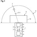
- Figure 1 shows in a highly schematic representation an embodiment of the sensor 1 according to the invention.
- the sensor 1 is generally designed for protective field monitoring and can be used in particular for monitoring danger areas on machines, systems, vehicles and the like.
- the sensor 1 is designed as a scanning sensor 1, in the present case as a surface distance sensor.
- the sensor 1 can be designed as a radar sensor or the like.
- the sensor 1 is designed as an optical sensor 1.
- the sensor 1 according to Figure 1 has distance sensor elements in such a way that in the present case it works according to a pulse transit time method.
- the distance measurements can also be carried out using a phase measurement method.
- the senor 1 has only one distance sensor element with a transmitter 3 emitting transmitted light beams 2 and a receiver 5 receiving received light beams 4. In general, several distance sensor elements can also be provided.
- the sensor 1 further comprises a deflection unit 6 with which the transmitted light beams 2 are periodically guided within a scanning area A, which in the present case extends over an angular range of 180 °.
- the deflection unit 6 can consist of a motor-driven rotating mirror arrangement or the like. The current deflection position of the deflection unit 6 and thus of the transmitted light rays 2 is determined by means of an angle transmitter (not shown).
- the distance of an object 7 to the sensor 1 is determined, in which the light transit time of pulse-shaped transmitted light beams 2 to the object 7 and back (as received light beams 4) is determined by the receiver 5. Together with the deflection position of the transmitted light beams 2 determined by means of the angle encoder, the position of the object 7 can thus be determined in an evaluation unit 8 of the sensor 1.
- a protective field 9 is specified in the evaluation unit 8.
- several protective fields 9 can also be specified in the evaluation unit 8, so that a suitable protective field 9 is activated depending on the requirements of the respective application.
- the evaluation unit 8 uses the determined position values to check whether an object 7 is present in the protective field 9. Accordingly, a binary switching signal is generated in the evaluation unit 8 as the object detection signal, the switching states of which indicate whether an object 7 is located within the protective field 9 or not.
- the sensor 1 can in particular be a safety sensor that is used to monitor the danger area on a system such as a machine or a vehicle.
- the safety sensor has a fail-safe structure.
- the evaluation unit 8 has a redundant structure, for example in the form of two computing units that monitor each other cyclically.
- the switching signal is output to a control unit in the system. If a dangerous state is present, that is, an object 7 is signaled in the protective field 9 with the switching signal, the control unit transfers the system to a safe state, with the system in particular being switched off.
- the protective field 9 activated in the sensor 1 is present in a user coordinate system.
- This user coordinate system differs from the measurement coordinate system of the sensor 1, the origin of which is, for example, at the location of the transmitter 3.
- the user coordinate system can advantageously be formed from a Cartesian coordinate system or a polar coordinate system.
- the protective field 9 is preferably specified in a user-specific manner.
- the protective field 9 can be input into the sensor 1, in particular its evaluation unit 8, via an input unit (not shown).
- the protective field or fields 9 are calculated in the evaluation unit 8 as a function of parameter values.
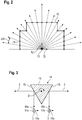
- the protective field 9 is converted from the user coordinate system into the measurement coordinate system in the evaluation unit. Alternatively, the conversion can take place during the configuration of the sensor 1 in the input unit. In particular, the protective field boundaries 10 of the protective field 9 are thus present in the measurement coordinate system. This considerably simplifies the computational effort in the evaluation unit 8 for determining whether an object 7 is present in the protective field 9. For this purpose, distance values determined for individual angular positions only have to be compared with the value 11 of the protective field boundary 10 of the protective field 9 assigned to this angular position (FIG. 2).
- Figure 2 shows a protective field 9 in the user coordinate system, with FIG Figure 2 the coordinate axes 12 and the origin 13 of the user coordinate system are shown, which in the present case is formed by a Cartesian coordinate system.
- the values 11 of the protective field boundary 10 are defined for individual discrete angle values in an equidistant angular grid .DELTA.W. These values 11 of the protective field boundary 10 are converted by the user coordinate system into the measurement coordinate system, the values 11 there possibly no longer being present in equidistant angular steps.
- measurement errors can be corrected when transforming measurement values from the at least one measurement coordinate system into the user coordinate system.
- measurement errors are stored in at least one correction table which is included in the transformation of the measurement values from the at least one measurement coordinate system into the user coordinate system.
- Figure 3 shows a variant of the optoelectronic components for the sensor 1 according to FIG Figure 1 .
- a polygon mirror 14 with three mirror surfaces 15 rotating about an axis of rotation D is provided as deflection unit 6.
- the sensor 1 has two distance sensor elements, of which only the transmitters 3 are shown.
- the transmitters 3 are assigned to the deflection unit 6 in such a way that the transmitted light beams 2 from the transmitters 3 are deflected on adjacent mirror surfaces 15.
- the transmitted light beams 2 are periodically guided in a scanning area A each.
- each transmitter 3 being assigned a measurement coordinate system.
- Figure 3 the coordinate axes 16a, b and the origins 17a, b of these measuring coordinate systems are shown.
- the activated protective field 9 is converted from the user coordinate system into the two measurement coordinate systems, so that for object detection within each measurement coordinate system for an angular position it is determined whether a detected distance value lies within the protective field boundary 10.
Landscapes
- Engineering & Computer Science (AREA)
- Physics & Mathematics (AREA)
- Radar, Positioning & Navigation (AREA)
- Remote Sensing (AREA)
- General Engineering & Computer Science (AREA)
- Computer Networks & Wireless Communication (AREA)
- General Physics & Mathematics (AREA)
- Mechanical Engineering (AREA)
- Electromagnetism (AREA)
- Length Measuring Devices With Unspecified Measuring Means (AREA)
- Optical Radar Systems And Details Thereof (AREA)
Abstract
Description
- Die Erfindung betrifft einen Sensor gemäß dem Oberbegriff des Anspruchs 1.
- Derartige Sensoren können als scannende Systeme ausgebildet sein, mittels derer Objekte in einem flächigen Überwachungsbereich geführt werden. Insbesondere können diese Sensoren als Flächendistanzsensoren ausgebildet sein, das heißt als distanzmessende scannende Systeme. Damit ist es möglich die Positionen von Objekten im Überwachungsbereich zu bestimmen.
- Diese Sensoren können wenigstens einen Distanzsensor mit einem Sendestrahlen emittierenden Sender und einem Empfangsstrahlen empfangenden Empfänger umfassen. Weiterhin ist eine Ablenkeinheit vorgesehen, mittels derer die Sendestrahlen periodisch in einem Abtastbereich abgelenkt werden. Typischerweise führt die Ablenkeinheit eine Drehbewegung aus, durch welche die Sendestrahlen in einem in einer Ebene liegenden Abtastbereich geführt sind. Zur Positionsbestimmung von Objekten im Abtastbereich werden die aktuell mit dem Distanzsensor ermittelten Entfernungswerte sowie die aktuellen Ablenkpositionen der Sendestrahlen verwendet, die insbesondere mittels eines Winkelgebers bestimmt werden.
- Diese Sensoren können für Schutzfeldüberwachungen eingesetzt werden. In diesem Fall generieren die Sensoren als Objektfeststellungssignal ein binäres Schaltsignal, das angibt ob sich ein Objekt im Schutzfeld befindet oder nicht. Typische Anwendungsbereiche derartiger Sensoren sind Gefahrenbereichsüberwachungen.
- Das jeweilige Schutzfeld wird vorteilhaft applikationsspezifisch vorgegeben. Typischerweise kann ein Benutzer die Schutzfelddaten über eine Eingabeeinheit in den Sensor eingeben.
- Bei Sensoren mit komplexen Optik-Aufbauten, insbesondere dann, wenn der Sender so zur Ablenkeinheit positioniert ist, dass die Strahlachse der Sendestrahlen nicht mit der Drehachse der Ablenkeinheit zusammenfällt, kann zur Auswertung der Messwerte und insbesondere zur Generierung eines Objektfeststellungssignals ein beträchtlicher Rechenaufwand erforderlich sein. Dieses Problem wird dadurch noch vergrößert, dass mit den Sensorkomponenten des Sensors in sehr kurzen Zeitintervallen viele Messwerte generiert werden, die möglichst verzögerungsfrei ausgewertet werden müssen.
- Dabei ist insbesondere nachteilig, dass das Schutzfeld in einem bedienerfreundlichen Benutzerkoordinatensystem vorgegeben wird, jedoch die Messwerte nicht in diesem Benutzerkoordinatensystem vorliegen, was fortlaufende Umrechnungen der Messwerte erforderlich macht. Insbesondere können die Messwerte in zeitabhängigen Koordinatensystemen vorliegen. Dies führt zu einer weiteren Erhöhung des Rechenaufwands.
- Weiterhin ist nachteilig, dass die vom Sensor generierten Messwerte mit systematischen Fehlern behaftet sein können. Derartige Messfehler können beispielsweise durch einen nicht exakten Einbau von Sensorkomponenten im Sensor bedingt sein.
- Der Erfindung liegt die Aufgabe zugrunde einen Sensor der eingangs genannten Art bereitzustellen, welcher bei geringem konstruktivem Aufwand eine hohe Funktionalität aufweist.
- Zur Lösung dieser Aufgabe sind die Merkmale des Anspruchs 1 vorgesehen. Vorteilhafte Ausführungsformen sind in den abhängigen Ansprüchen beschrieben.
- Die Erfindung betrifft einen Sensor zur Erfassung von Objekten innerhalb eines Schutzfelds mit Sensorkomponenten zur Objekterfassung und mit einer Auswerteeinheit zur Auswertung von Messwerten der Sensorkomponenten. Die Messwerte der Sensorkomponenten liegen in wenigstens einem Messkoordinatensystem vor. Das Schutzfeld ist in einem Benutzerkoordinatensystem vorgebbar. Für eine Erfassung von Objekten werden innerhalb des Schutzfelds die Messwerte der Sensorkomponenten in der Auswerteeinheit fortlaufend in das Benutzerkoordinatensystem umgerechnet. In der Auswerteeinheit wird ein Vergleich von Messwerten der Sensorkomponenten mit Schutzfelddaten des Schutzfelds in dem Benutzerkoordinatensystem durchgeführt. Bei der Transformation von Messwerten werden Messfehler korrigiert, die in einer Korrekturtabelle hinterlegt sind, welche in die Transformation der Messwerte einbezogen ist.
- In diesem Fall werden die bei der Objekterfassung erhaltenen Messwerte fortlaufend in das Benutzerkoordinatensystem umgerechnet und mit dem im Benutzerkoordinatensystem vorliegenden Schutzfeld in Beziehung gesetzt um daraus das Objektfeststellungssignal zu generieren.
- Messfehler können sich durch einen fehlerhaften Einbau von Komponenten des Sensors ergeben. Wird zum Beispiel der Sender versetzt zu seiner Sollposition eingebaut ergibt sich ein fehlerhafter Offset der Messwerte. Gleiches gilt, wenn zum Beispiel eine einen Winkelgeber bildende Encoderscheibe mit einem Versatz zur Solllage eingebaut wird. Auch können elektronisch vorgegebene Zeitnullpunkte für durchzuführende Distanzmessungen mit einem fehlerhaften Offset versehen sein.
- Durch Einmessvorgänge können derartige Messfehler erfasst werden und mittels der Korrekturtabellen eliminiert werden.
- Der erfindungsgemäße Sensor ist generell für eine Schutzfeldüberwachung ausgebildet. Mit einem derartigen Sensor können insbesondere Gefahrenbereiche an Maschinen oder Anlagen überwacht werden. Auch ist es möglich, den Sensor an einem Fahrzeug anzubringen, so dass innerhalb eines Schutzfelds das Vorfeld des Fahrzeugs überwacht werden kann. Für den Einsatz im Bereich der Sicherheitstechnik ist der Sensor als Sicherheitssensor ausgebildet, der einen fehlersicheren Aufbau aufweist. Der fehlersichere Aufbau wird insbesondere durch eine redundante Auswerteeinheit realisiert.
- Der erfindungsgemäße Sensor ist vorteilhaft ein scannender Sensor, insbesondere ein Flächendistanzsensor.
- Vorteilhaft weist der Sensor wenigstens einen Sendestrahlen emittierenden Sender, wenigstens einen Empfangsstrahlen empfangenden Empfänger und eine Ablenkeinheit zur periodischen Ablenkung der Sendestrahlen in einem Abtastbereich auf.
- Durch die Ablenkeinheit werden die Sendestrahlen periodisch in einem Winkelbereich abgelenkt. Für die einzelnen Winkelpositionen werden Messwerte, insbesondere Distanzwerte generiert. Durch die Erfassung der aktuellen Winkelpositionen mit einem Winkelgeber und die ermittelten Distanzwerte können Positionen von Objekten bestimmt werden.
- Prinzipiell kann der Sensor als Radarsensor oder dergleichen ausgebildet sein. Besonders vorteilhaft ist der Sensor als optischer Sensor ausgebildet.
- Das Schutzfeld wird vorteilhaft für die jeweilige Applikation spezifisch vorgegeben. Auch können mehrere Schutzfelder vorgesehen sein, die vorteilhaft im Sensor abgespeichert sein können, so dass entsprechend den aktuellen Anforderungen das jeweils geeignete Schutzfeld aktiviert wird.
- Die Schutzfelder werden typischerweise in einem Konfigurations- oder Einlernprozess definiert, wobei erfindungsgemäß das oder die Schutzfelder in einem Benutzerkoordinatensystem vorgegeben sind.
- Beispielsweise sind das oder die Schutzfelder über eine Eingabeeinheit eingebbar.
- Alternativ können das oder die Schutzfelder abhängig von Parameterwerten in der Auswerteeinheit berechnet werden.
- Die Darstellung des oder der Schutzfelder in dem Benutzerkoordinatensystem ermöglicht einem Benutzer eine einfache visuelle Anzeige und auch Kontrollmöglichkeit. Eine besonders benutzerfreundliche Darstellung ergibt sich, wenn das Benutzerkoordinatensystem ein kartesisches Koordinatensystem oder ein Polarkoordinatensystem ist.
- Dabei ist ein Schutzfeld generell durch Schutzfeldgrenzen definiert, die dieses Schutzfeld begrenzen. Zweckmäßig ist das oder jedes Schutzfeld im Benutzerkoordinatensystem mit äquidistanten Winkelschritten vorgegeben.
- Als ein Schutzfeld kennzeichnende Schutzfelddaten liegen somit eine Vielzahl an Wertepaaren von Schutzfeldgrenzen und zugeordneten Winkelwerten vor.
- Die Erfindung wird im Folgenden anhand der Zeichnungen erläutert. Es zeigen:
- Figur 1
- Schematische Darstellung eines Ausführungsbeispiels des erfindungsgemäßen Sensors.
- Figur 2
- Einzeldarstellung eines Schutzfelds für den erfindungsgemäßen Sensor.
- Figur 3
- Ausführungsbeispiel einer Ablenkeinheit mit zwei zugeordneten Sendern für den erfindungsgemäßen Sensor.
-
Figur 1 zeigt in einer stark schematisierten Darstellung ein Ausführungsbeispiel des erfindungsgemäßen Sensors 1. Der Sensor 1 ist generell für eine Schutzfeldüberwachung ausgebildet und kann insbesondere für Gefahrenbereichsüberwachung an Maschinen, Anlagen, Fahrzeugen und dergleichen eingesetzt werden. - Der Sensor 1 ist als scannender Sensor 1 ausgebildet, im vorliegenden Fall als Flächendistanzsensor. Prinzipiell kann der Sensor 1 als Radarsensor oder dergleichen ausgebildet sein. Im vorliegenden Fall ist der Sensor 1 als optischer Sensor 1 ausgebildet.
- Der Sensor 1 gemäß
Figur 1 weist Distanzsensorelemente derart auf, dass dieser im vorliegenden Fall nach einem Impuls-Laufzeit-Verfahren arbeitet. Prinzipiell können die Distanzmessungen auch nach einem Phasenmessverfahren erfolgen. - Der Sensor 1 weist im vorliegenden Fall nur ein Distanzsensorelemente mit einem Sendelichtstrahlen 2 emittierenden Sender 3 und einem Empfangslichtstrahlen 4 empfangenden Empfänger 5 auf. Generell können auch mehrere Distanzsensorelemente vorgesehen sein.
- Der Sensor 1 umfasst weiterhin eine Ablenkeinheit 6 mit der die Sendelichtstrahlen 2 periodisch innerhalb eines Abtastbereichs A geführt sind, der sich im vorliegenden Fall über einen Winkelbereich von 180° erstreckt. Die Ablenkeinheit 6 kann aus einer motorisch getriebenen Drehspiegelanordnung oder dergleichen bestehen. Mittels eines nicht dargestellten Winkelgebers wird die aktuelle Ablenkposition der Ablenkeinheit 6 und damit der Sendelichtstrahlen 2 ermittelt.
- Mit dem Distanzsensorelement wird die Distanz eines Objekts 7 zum Sensor 1 ermittelt, in dem die Lichtlaufzeit von pulsförmigen Sendelichtstrahlen 2 zum Objekt 7 und zurück (als Empfangslichtstrahlen 4) vom Empfänger 5 ermittelt wird. Zusammen mit der mittels des Winkelgebers ermittelten Ablenkposition der Sendelichtstrahlen 2 kann so in einer Auswerteeinheit 8 des Sensors 1 die Position des Objekts 7 ermittelt werden.
- Erfindungsgemäß ist in der Auswerteeinheit 8 ein Schutzfeld 9 vorgegeben. Generell können in der Auswerteeinheit 8 auch mehrere Schutzfelder 9 vorgegeben sein, so dass je nach Anforderung an die jeweilige Applikation ein geeignetes Schutzfeld 9 aktiviert wird.
- In der Auswerteeinheit 8 wird anhand der ermittelten Positionswerte geprüft, ob ein Objekt 7 im Schutzfeld 9 vorhanden ist. Dementsprechend wird in der Auswerteeinheit 8 als Objektfeststellungssignal ein binäres Schaltsignal generiert, dessen Schaltzustände angeben, ob sich ein Objekt 7 innerhalb des Schutzfelds 9 befindet oder nicht.
- Der Sensor 1 kann insbesondere ein Sicherheitssensor sein, der zur Gefahrenbereichsüberwachung an einer Anlage wie einer Maschine oder einem Fahrzeug eingesetzt wird. Zur Erfüllung der hierfür geltenden Sicherheitsanforderungen weist der Sicherheitssensor einen fehlersicheren Aufbau auf. Insbesondere weist die Auswerteeinheit 8 einen redundanten Aufbau auf, beispielsweise in Form von zwei sich gegenseitig zyklisch überwachenden Recheneinheiten.
- Das Schaltsignal wird an eine Steuereinheit der Anlage ausgegeben. Liegt ein gefährlicher Zustand vor, das heißt wird mit dem Schaltsignal ein Objekt 7 im Schutzfeld 9 signalisiert, überführt die Steuereinheit die Anlage in einen sicheren Zustand, wobei insbesondere die Anlage abgeschaltet wird.
- Das im Sensor 1 aktivierte Schutzfeld 9 liegt in einem Benutzerkoordinatensystem vor. Dieses Benutzerkoordinatensystem unterscheidet sich zum Messkoordinatensystem des Sensors 1, dessen Ursprung zum Beispiel am Ort des Senders 3 liegt. Das Benutzerkoordinatensystem kann vorteilhaft von einem kartesischen Koordinatensystem oder einem Polarkoordinatensystem gebildet sein.
- Das Schutzfeld 9 wird vorzugsweise benutzerspezifisch vorgegeben. Insbesondere kann das Schutzfeld 9 über eine nicht dargestellte Eingabeeinheit in den Sensor 1, insbesondere dessen Auswerteeinheit 8 eingegeben werden. Alternativ werden das oder die Schutzfelder 9 abhängig von Parameterwerten in der Auswerteeinheit 8 berechnet.
- Zu Beginn des Sensorbetriebs wird in der Auswerteeinheit das Schutzfeld 9 vom Benutzerkoordinatensystem in das Messkoordinatensystem umgerechnet. Alternativ kann die Umrechnung während der Konfiguration des Sensors 1 in der Eingabeeinheit erfolgen. Damit liegen insbesondere die Schutzfeldgrenzen 10 des Schutzfelds 9 im Messkoordinatensystem vor. Damit wird der Rechenaufwand in der Auswerteeinheit 8 zur Ermittlung, ob ein Objekt 7 im Schutzfeld 9 vorhanden ist, erheblich vereinfacht. Hierzu müssen lediglich für einzelne Winkelpositionen ermittelte Distanzwerte mit dem dieser Winkelposition zugeordneten Wert 11 der Schutzfeldgrenze 10 des Schutzfelds 9 verglichen werden (Figur 2).
- Vorteilhaft werden bei dem Koordinatensystem nur diskrete Werte 11 des Schutzfelds 9, insbesondere Werte 11 der Schutzfeldgrenze 10 vom Benutzerkoordinatensystem in das Messkoordinatensystem umgerechnet. Um auch im Messkoordinatensystem eine durchgehende Schutzfeldgrenze 10 zu schaffen, erfolgt eine Interpolation zwischen den diskreten Werten 11 der Schutzfeldgrenze 10.
- Dies ist beispielhaft in
Figur 2 dargestellt.Figur 2 zeigt ein Schutzfeld 9 im Benutzerkoordinatensystem, wobei inFigur 2 die Koordinatenachsen 12 und der Ursprung 13 des Benutzerkoordinatensystems dargestellt sind, das im vorliegenden Fall von einem kartesischen Koordinatensystem gebildet ist. - In einem äquidistanten Winkelraster ΔW sind für einzelne diskrete Winkelwerte die Werte 11 der Schutzfeldgrenze 10 definiert. Diese Werte 11 der Schutzfeldgrenze 10 werden von dem Benutzerkoordinatensystem in das Messkoordinatensystem umgerechnet, wobei dort möglicherweise die Werte 11 nicht mehr in äquidistanten Winkelschritten vorliegen.
- Weiterhin können bei einer Transformation von Messwerten von dem wenigstens einen Messkoordinatensystem in das Benutzerkoordinatensystem Messfehler korrigiert werden.
- Hierzu sind Messfehler in wenigstens einer Korrekturtabelle hinterlegt, welche in die Transformation der Messwerte von dem wenigstens einen Messkoordinatensystem in das Benutzerkoordinatensystem einbezogen ist.
-
Figur 3 zeigt eine Variante der optoelektronischen Komponenten für den Sensor 1 gemäßFigur 1 . - Bei der Ausführungsform gemäß
Figur 3 ist als Ablenkeinheit 6 ein um eine Drehachse D rotierender Polygonspiegel 14 mit drei Spiegelflächen 15 vorgesehen. - Der Sensor 1 weist im vorliegenden Fall zwei Distanzsensorelemente auf, von denen lediglich die Sender 3 dargestellt sind. Die Sender 3 sind der Ablenkeinheit 6 so zugeordnet, dass die Sendelichtstrahlen 2 der Sender 3 an benachbarten Spiegelflächen 15 umgelenkt werden. Durch die Drehbewegung der Ablenkeinheit 6 werden die Sendelichtstrahlen 2 periodisch jeweils in einem Abtastbereich A geführt.
- Im vorliegenden Fall sind zwei Messkoordinatensysteme vorgesehen, wobei jedem Sender 3 ein Messkoordinatensystem zugeordnet ist. In
Figur 3 sind die Koordinatenachsen 16a, b und die Ursprünge 17 a, b dieser Messkoordinatensysteme dargestellt. - In diesem Fall wird vor Aufnahme des Sensorbetriebs das aktivierte Schutzfeld 9 aus dem Benutzerkoordinatensystem in die beiden Messkoordinatensysteme umgerechnet, so dass zur Objektdetektion innerhalb jedes Messkoordinatensystems für eine Winkelposition ermittelt wird, ob ein erfasster Distanzwert innerhalb der Schutzfeldgrenze 10 liegt.
-
- (1)
- Sensor
- (2)
- Sendelichtstrahl
- (3)
- Sender
- (4)
- Empfangslichtstrahl
- (5)
- Empfänger
- (6)
- Ablenkeinheit
- (7)
- Objekt
- (8)
- Auswerteeinheit
- (9)
- Schutzfeld
- (10)
- Schutzfeldgrenze
- (11)
- Wert
- (12)
- Koordinatenachse
- (13)
- Ursprung
- (14)
- Polygonspiegel
- (15)
- Spiegelfläche
- (16a,b)
- Koordinatenachse
- (17a,b)
- Ursprung
- (A)
- Abtastbereich
- (D)
- Drehachse
- (ΔW)
- Winkelraster
Claims (12)
- Sensor (1) zur Erfassung von Objekten (7) innerhalb eines Schutzfelds (9) mit Sensorkomponenten zur Objekterfassung und mit einer Auswerteeinheit (8) zur Auswertung von Messwerten der Sensorkomponenten, dadurch gekennzeichnet, dass die Messwerte der Sensorkomponenten in wenigstens einem Messkoordinatensystem vorliegen, dass das Schutzfeld (9) in einem Benutzerkoordinatensystem vorgebbar ist und dass für eine Erfassung von Objekten (7) innerhalb des Schutzfelds (9) die Messwerte der Sensorkomponenten in der Auswerteeinheit (8) fortlaufend in das Benutzerkoordinatensystem umgerechnet werden und in der Auswerteeinheit (8) ein Vergleich von Messwerten der Sensorkomponenten mit Schutzfelddaten des Schutzfelds (9) in dem Benutzerkoordinatensystem durchgeführt wird, und dass bei einer Transformation von Messwerten Messfehler korrigiert werden, wobei Messfehler in wenigstens einer Korrekturtabelle hinterlegt sind, welche in die Transformation der Messwerte einbezogen ist.
- Sensor (1) nach Anspruch 1, dadurch gekennzeichnet, dass bei einer Koordinatentransformation Interpolationen durchgeführt werden.
- Sensor (1) nach einem der Ansprüche 1 oder 2, dadurch gekennzeichnet, dass für diesen mehrere Schutzfelder (9) vorgebbar sind.
- Sensor (1) nach einem der Ansprüche 1-3, dadurch gekennzeichnet, dass das oder die Schutzfelder (9) über eine Eingabeeinheit eingebbar sind oder abhängig von Parameterwerten in der Auswerteeinheit (8) berechnet werden.
- Sensor (1) nach einem der Ansprüche 1-4, dadurch gekennzeichnet, dass ein Schutzfeld (9) kennzeichnende Schutzfelddaten von Schutzfeldgrenzen (10) gebildet sind.
- Sensor (1) nach einem der Ansprüche 1-5, dadurch gekennzeichnet, dass das Benutzerkoordinatensystem ein kartesisches Koordinatensystem oder ein Polarkoordinatensystem ist.
- Sensor (1) nach Anspruch 6, dadurch gekennzeichnet, dass das oder jedes Schutzfeld (9) im Benutzerkoordinatensystem mit äquidistanten Winkelschritten vorgegeben ist.
- Sensor (1) nach einem der Ansprüche 1-7, dadurch gekennzeichnet, dass wenigstens zwei Messkoordinatensysteme vorgesehen sind.
- Sensor (1) nach einem der Ansprüche 1-8, dadurch gekennzeichnet, dass dieser ein optischer Sensor, insbesondere ein scannender Sensor (1) oder ein Flächendistanzsensor ist.
- Sensor (1) nach einem der Ansprüche 1-9, dadurch gekennzeichnet, dass dieser wenigstens einen Senderstrahlen emittierenden Sender (3), wenigstens einen Empfangsstrahlen empfangenden Empfänger (5) und eine Ablenkeinheit (6) zur periodischen Ableitung der Sendestrahlen in einem Abtastbereich (A) aufweist.
- Sensor (1) nach einem der Ansprüche 1-10 dadurch gekennzeichnet, dass in der Auswerteeinheit (8) abhängig von Messwerten der Sensorkomponenten ein Objektfeststellungssignal generiert wird.
- Sensor (1) nach Anspruch 11, dadurch gekennzeichnet, dass das Objektfeststellungssignal ein binäres Schaltsignal ist, dessen Schaltzustände angeben, ob sich ein Objekt im Schutzfeld (9) befindet oder nicht.
Applications Claiming Priority (2)
| Application Number | Priority Date | Filing Date | Title |
|---|---|---|---|
| DE202019105315.1U DE202019105315U1 (de) | 2019-09-25 | 2019-09-25 | Sensor |
| EP20177946.9A EP3798668B1 (de) | 2019-09-25 | 2020-06-03 | Sensor |
Related Parent Applications (2)
| Application Number | Title | Priority Date | Filing Date |
|---|---|---|---|
| EP20177946.9A Division EP3798668B1 (de) | 2019-09-25 | 2020-06-03 | Sensor |
| EP20177946.9A Division-Into EP3798668B1 (de) | 2019-09-25 | 2020-06-03 | Sensor |
Publications (2)
| Publication Number | Publication Date |
|---|---|
| EP3822656A1 true EP3822656A1 (de) | 2021-05-19 |
| EP3822656B1 EP3822656B1 (de) | 2024-03-13 |
Family
ID=74188675
Family Applications (2)
| Application Number | Title | Priority Date | Filing Date |
|---|---|---|---|
| EP20214071.1A Active EP3822656B1 (de) | 2019-09-25 | 2020-06-03 | Sensor |
| EP20177946.9A Active EP3798668B1 (de) | 2019-09-25 | 2020-06-03 | Sensor |
Family Applications After (1)
| Application Number | Title | Priority Date | Filing Date |
|---|---|---|---|
| EP20177946.9A Active EP3798668B1 (de) | 2019-09-25 | 2020-06-03 | Sensor |
Country Status (2)
| Country | Link |
|---|---|
| EP (2) | EP3822656B1 (de) |
| DE (1) | DE202019105315U1 (de) |
Families Citing this family (1)
| Publication number | Priority date | Publication date | Assignee | Title |
|---|---|---|---|---|
| DE202023107245U1 (de) * | 2023-12-07 | 2025-03-12 | Leuze Electronic Gmbh & Co. Kg | Sensoranordnung |
Citations (5)
| Publication number | Priority date | Publication date | Assignee | Title |
|---|---|---|---|---|
| DE10128954A1 (de) * | 2001-06-15 | 2002-12-19 | Ibeo Automobile Sensor Gmbh | Korrekturverfahren für Daten mehrerer optoelektronischer Sensoren |
| DE102004043515A1 (de) * | 2004-09-08 | 2006-03-09 | Sick Ag | Verfahren und Vorrichtung zum Erfassen eines Objekts |
| US20090091447A1 (en) * | 2007-10-09 | 2009-04-09 | Optex Co., Ltd. | Laser area sensor |
| US20170242110A1 (en) * | 2016-02-22 | 2017-08-24 | Keyence Corporation | Optical Safety System |
| US20180348347A1 (en) * | 2017-06-06 | 2018-12-06 | Microvision, Inc. | Scanned Beam Display with Multiple Detector Rangefinding |
Family Cites Families (6)
| Publication number | Priority date | Publication date | Assignee | Title |
|---|---|---|---|---|
| DE10143107A1 (de) | 2001-09-03 | 2003-03-20 | Sick Ag | Optoelektronische Entfernungsmeßeinrichtung |
| JP5036624B2 (ja) | 2008-05-20 | 2012-09-26 | 株式会社キーエンス | 監視エリア設定装置 |
| JP2010175488A (ja) | 2009-01-31 | 2010-08-12 | Keyence Corp | 光走査型光電スイッチ |
| EP2315052B1 (de) * | 2009-10-22 | 2012-02-29 | Sick Ag | Sicherheitsscanner |
| US20120123563A1 (en) | 2010-11-17 | 2012-05-17 | Omron Scientific Technologies, Inc. | Method and Apparatus for Monitoring Zones |
| JP6637331B2 (ja) | 2016-02-22 | 2020-01-29 | 株式会社キーエンス | 安全スキャナ及び光学安全システム |
-
2019
- 2019-09-25 DE DE202019105315.1U patent/DE202019105315U1/de active Active
-
2020
- 2020-06-03 EP EP20214071.1A patent/EP3822656B1/de active Active
- 2020-06-03 EP EP20177946.9A patent/EP3798668B1/de active Active
Patent Citations (5)
| Publication number | Priority date | Publication date | Assignee | Title |
|---|---|---|---|---|
| DE10128954A1 (de) * | 2001-06-15 | 2002-12-19 | Ibeo Automobile Sensor Gmbh | Korrekturverfahren für Daten mehrerer optoelektronischer Sensoren |
| DE102004043515A1 (de) * | 2004-09-08 | 2006-03-09 | Sick Ag | Verfahren und Vorrichtung zum Erfassen eines Objekts |
| US20090091447A1 (en) * | 2007-10-09 | 2009-04-09 | Optex Co., Ltd. | Laser area sensor |
| US20170242110A1 (en) * | 2016-02-22 | 2017-08-24 | Keyence Corporation | Optical Safety System |
| US20180348347A1 (en) * | 2017-06-06 | 2018-12-06 | Microvision, Inc. | Scanned Beam Display with Multiple Detector Rangefinding |
Also Published As
| Publication number | Publication date |
|---|---|
| EP3822656B1 (de) | 2024-03-13 |
| EP3798668A1 (de) | 2021-03-31 |
| EP3798668B1 (de) | 2024-03-13 |
| DE202019105315U1 (de) | 2021-01-05 |
Similar Documents
| Publication | Publication Date | Title |
|---|---|---|
| EP1494048B1 (de) | Lichtgitter | |
| DE10312972B3 (de) | Optischer Sensor | |
| DE102019132024A1 (de) | Sicherheitssystem | |
| EP3217195B1 (de) | Optischer sensor | |
| EP3287809B1 (de) | Verfahren zum betreiben eines scanners und scanner | |
| EP3587894A1 (de) | Sensoranordnung und verfahren zum betrieb einer sensoranordnung | |
| EP3822656A1 (de) | Sensor | |
| EP4435313A1 (de) | System und verfahren zur überwachung eines gefahrenbereichs einer maschine | |
| EP2331912B1 (de) | Anordnung und verfahren zur erzeugung eines referenzimpulses für ein positionsmessgerät | |
| EP2811318B1 (de) | Optoelektronischer Sensor | |
| EP3640522B1 (de) | Überwachungsvorrichtung | |
| EP2891024A1 (de) | Bedienvorrichtung für eine funktionseinrichtung eines kraftfahrzeugs | |
| DE102018113359A1 (de) | Sensorsystem mit optoelektronischen Distanzsensoren | |
| EP3540380B1 (de) | Überwachungsanordnung für eine anlage | |
| EP3640521B1 (de) | Überwachungsvorrichtung | |
| EP4244651B1 (de) | Verbesserte funktionsüberprüfung eines laserscanners | |
| DE202019105317U1 (de) | Sensor | |
| EP3877798A1 (de) | VERFAHREN UND MESSSYSTEM ZUR ERMITTLUNG DER GRÖßE DER SCHWINGUNGSAMPLITUDE EINES MIKRO-SCHWINGSPIEGELS EINER OBJEKTERFASSUNGSVORRICHTUNG | |
| EP3062180B1 (de) | Verfahren zur überprüfung der positioniergenauigkeit eines mittels eines antriebs und einer steuerung bezüglich wenigstens einer achse verstellbaren maschinenteils | |
| DE102011101235B4 (de) | Elektronisches und/oder optisches Gerät mit wenigstens einer Eingabeeinrichtung | |
| EP3955022A1 (de) | Sensoranordnung und verfahren zu deren betrieb | |
| EP3663797A1 (de) | Überwachungsvorrichtung | |
| DE102023105389A1 (de) | Überwachungssystem | |
| EP4592581A1 (de) | Überwachungseinrichtung | |
| DE202023101035U1 (de) | Überwachungssystem |
Legal Events
| Date | Code | Title | Description |
|---|---|---|---|
| PUAI | Public reference made under article 153(3) epc to a published international application that has entered the european phase |
Free format text: ORIGINAL CODE: 0009012 |
|
| STAA | Information on the status of an ep patent application or granted ep patent |
Free format text: STATUS: THE APPLICATION HAS BEEN PUBLISHED |
|
| STAA | Information on the status of an ep patent application or granted ep patent |
Free format text: STATUS: REQUEST FOR EXAMINATION WAS MADE |
|
| AC | Divisional application: reference to earlier application |
Ref document number: 3798668 Country of ref document: EP Kind code of ref document: P |
|
| AK | Designated contracting states |
Kind code of ref document: A1 Designated state(s): AL AT BE BG CH CY CZ DE DK EE ES FI FR GB GR HR HU IE IS IT LI LT LU LV MC MK MT NL NO PL PT RO RS SE SI SK SM TR |
|
| 17P | Request for examination filed |
Effective date: 20210512 |
|
| RBV | Designated contracting states (corrected) |
Designated state(s): AL AT BE BG CH CY CZ DE DK EE ES FI FR GB GR HR HU IE IS IT LI LT LU LV MC MK MT NL NO PL PT RO RS SE SI SK SM TR |
|
| RIC1 | Information provided on ipc code assigned before grant |
Ipc: F16P 3/14 20060101ALI20231124BHEP Ipc: G01S 7/295 20060101ALI20231124BHEP Ipc: G01S 7/497 20060101ALI20231124BHEP Ipc: G01S 17/42 20060101ALI20231124BHEP Ipc: G01S 7/48 20060101AFI20231124BHEP |
|
| GRAP | Despatch of communication of intention to grant a patent |
Free format text: ORIGINAL CODE: EPIDOSNIGR1 |
|
| STAA | Information on the status of an ep patent application or granted ep patent |
Free format text: STATUS: GRANT OF PATENT IS INTENDED |
|
| INTG | Intention to grant announced |
Effective date: 20240109 |
|
| GRAS | Grant fee paid |
Free format text: ORIGINAL CODE: EPIDOSNIGR3 |
|
| GRAA | (expected) grant |
Free format text: ORIGINAL CODE: 0009210 |
|
| STAA | Information on the status of an ep patent application or granted ep patent |
Free format text: STATUS: THE PATENT HAS BEEN GRANTED |
|
| AC | Divisional application: reference to earlier application |
Ref document number: 3798668 Country of ref document: EP Kind code of ref document: P |
|
| AK | Designated contracting states |
Kind code of ref document: B1 Designated state(s): AL AT BE BG CH CY CZ DE DK EE ES FI FR GB GR HR HU IE IS IT LI LT LU LV MC MK MT NL NO PL PT RO RS SE SI SK SM TR |
|
| REG | Reference to a national code |
Ref country code: GB Ref legal event code: FG4D Free format text: NOT ENGLISH |
|
| REG | Reference to a national code |
Ref country code: CH Ref legal event code: EP |
|
| REG | Reference to a national code |
Ref country code: DE Ref legal event code: R096 Ref document number: 502020007329 Country of ref document: DE |
|
| REG | Reference to a national code |
Ref country code: IE Ref legal event code: FG4D Free format text: LANGUAGE OF EP DOCUMENT: GERMAN |
|
| P01 | Opt-out of the competence of the unified patent court (upc) registered |
Effective date: 20240328 |
|
| PG25 | Lapsed in a contracting state [announced via postgrant information from national office to epo] |
Ref country code: LT Free format text: LAPSE BECAUSE OF FAILURE TO SUBMIT A TRANSLATION OF THE DESCRIPTION OR TO PAY THE FEE WITHIN THE PRESCRIBED TIME-LIMIT Effective date: 20240313 |
|
| REG | Reference to a national code |
Ref country code: LT Ref legal event code: MG9D |
|
| PG25 | Lapsed in a contracting state [announced via postgrant information from national office to epo] |
Ref country code: GR Free format text: LAPSE BECAUSE OF FAILURE TO SUBMIT A TRANSLATION OF THE DESCRIPTION OR TO PAY THE FEE WITHIN THE PRESCRIBED TIME-LIMIT Effective date: 20240614 |
|
| REG | Reference to a national code |
Ref country code: NL Ref legal event code: MP Effective date: 20240313 |
|
| PG25 | Lapsed in a contracting state [announced via postgrant information from national office to epo] |
Ref country code: HR Free format text: LAPSE BECAUSE OF FAILURE TO SUBMIT A TRANSLATION OF THE DESCRIPTION OR TO PAY THE FEE WITHIN THE PRESCRIBED TIME-LIMIT Effective date: 20240313 Ref country code: RS Free format text: LAPSE BECAUSE OF FAILURE TO SUBMIT A TRANSLATION OF THE DESCRIPTION OR TO PAY THE FEE WITHIN THE PRESCRIBED TIME-LIMIT Effective date: 20240613 |
|
| PG25 | Lapsed in a contracting state [announced via postgrant information from national office to epo] |
Ref country code: ES Free format text: LAPSE BECAUSE OF FAILURE TO SUBMIT A TRANSLATION OF THE DESCRIPTION OR TO PAY THE FEE WITHIN THE PRESCRIBED TIME-LIMIT Effective date: 20240313 |
|
| PG25 | Lapsed in a contracting state [announced via postgrant information from national office to epo] |
Ref country code: RS Free format text: LAPSE BECAUSE OF FAILURE TO SUBMIT A TRANSLATION OF THE DESCRIPTION OR TO PAY THE FEE WITHIN THE PRESCRIBED TIME-LIMIT Effective date: 20240613 Ref country code: NO Free format text: LAPSE BECAUSE OF FAILURE TO SUBMIT A TRANSLATION OF THE DESCRIPTION OR TO PAY THE FEE WITHIN THE PRESCRIBED TIME-LIMIT Effective date: 20240613 Ref country code: LT Free format text: LAPSE BECAUSE OF FAILURE TO SUBMIT A TRANSLATION OF THE DESCRIPTION OR TO PAY THE FEE WITHIN THE PRESCRIBED TIME-LIMIT Effective date: 20240313 Ref country code: HR Free format text: LAPSE BECAUSE OF FAILURE TO SUBMIT A TRANSLATION OF THE DESCRIPTION OR TO PAY THE FEE WITHIN THE PRESCRIBED TIME-LIMIT Effective date: 20240313 Ref country code: GR Free format text: LAPSE BECAUSE OF FAILURE TO SUBMIT A TRANSLATION OF THE DESCRIPTION OR TO PAY THE FEE WITHIN THE PRESCRIBED TIME-LIMIT Effective date: 20240614 Ref country code: FI Free format text: LAPSE BECAUSE OF FAILURE TO SUBMIT A TRANSLATION OF THE DESCRIPTION OR TO PAY THE FEE WITHIN THE PRESCRIBED TIME-LIMIT Effective date: 20240313 Ref country code: ES Free format text: LAPSE BECAUSE OF FAILURE TO SUBMIT A TRANSLATION OF THE DESCRIPTION OR TO PAY THE FEE WITHIN THE PRESCRIBED TIME-LIMIT Effective date: 20240313 Ref country code: BG Free format text: LAPSE BECAUSE OF FAILURE TO SUBMIT A TRANSLATION OF THE DESCRIPTION OR TO PAY THE FEE WITHIN THE PRESCRIBED TIME-LIMIT Effective date: 20240313 |
|
| PG25 | Lapsed in a contracting state [announced via postgrant information from national office to epo] |
Ref country code: SE Free format text: LAPSE BECAUSE OF FAILURE TO SUBMIT A TRANSLATION OF THE DESCRIPTION OR TO PAY THE FEE WITHIN THE PRESCRIBED TIME-LIMIT Effective date: 20240313 Ref country code: LV Free format text: LAPSE BECAUSE OF FAILURE TO SUBMIT A TRANSLATION OF THE DESCRIPTION OR TO PAY THE FEE WITHIN THE PRESCRIBED TIME-LIMIT Effective date: 20240313 |
|
| PG25 | Lapsed in a contracting state [announced via postgrant information from national office to epo] |
Ref country code: NL Free format text: LAPSE BECAUSE OF FAILURE TO SUBMIT A TRANSLATION OF THE DESCRIPTION OR TO PAY THE FEE WITHIN THE PRESCRIBED TIME-LIMIT Effective date: 20240313 |
|
| PG25 | Lapsed in a contracting state [announced via postgrant information from national office to epo] |
Ref country code: NL Free format text: LAPSE BECAUSE OF FAILURE TO SUBMIT A TRANSLATION OF THE DESCRIPTION OR TO PAY THE FEE WITHIN THE PRESCRIBED TIME-LIMIT Effective date: 20240313 |
|
| PG25 | Lapsed in a contracting state [announced via postgrant information from national office to epo] |
Ref country code: IS Free format text: LAPSE BECAUSE OF FAILURE TO SUBMIT A TRANSLATION OF THE DESCRIPTION OR TO PAY THE FEE WITHIN THE PRESCRIBED TIME-LIMIT Effective date: 20240713 |
|
| PG25 | Lapsed in a contracting state [announced via postgrant information from national office to epo] |
Ref country code: SM Free format text: LAPSE BECAUSE OF FAILURE TO SUBMIT A TRANSLATION OF THE DESCRIPTION OR TO PAY THE FEE WITHIN THE PRESCRIBED TIME-LIMIT Effective date: 20240313 Ref country code: PT Free format text: LAPSE BECAUSE OF FAILURE TO SUBMIT A TRANSLATION OF THE DESCRIPTION OR TO PAY THE FEE WITHIN THE PRESCRIBED TIME-LIMIT Effective date: 20240715 |
|
| PG25 | Lapsed in a contracting state [announced via postgrant information from national office to epo] |
Ref country code: CZ Free format text: LAPSE BECAUSE OF FAILURE TO SUBMIT A TRANSLATION OF THE DESCRIPTION OR TO PAY THE FEE WITHIN THE PRESCRIBED TIME-LIMIT Effective date: 20240313 Ref country code: EE Free format text: LAPSE BECAUSE OF FAILURE TO SUBMIT A TRANSLATION OF THE DESCRIPTION OR TO PAY THE FEE WITHIN THE PRESCRIBED TIME-LIMIT Effective date: 20240313 |
|
| PG25 | Lapsed in a contracting state [announced via postgrant information from national office to epo] |
Ref country code: PL Free format text: LAPSE BECAUSE OF FAILURE TO SUBMIT A TRANSLATION OF THE DESCRIPTION OR TO PAY THE FEE WITHIN THE PRESCRIBED TIME-LIMIT Effective date: 20240313 |
|
| PG25 | Lapsed in a contracting state [announced via postgrant information from national office to epo] |
Ref country code: SK Free format text: LAPSE BECAUSE OF FAILURE TO SUBMIT A TRANSLATION OF THE DESCRIPTION OR TO PAY THE FEE WITHIN THE PRESCRIBED TIME-LIMIT Effective date: 20240313 |
|
| PG25 | Lapsed in a contracting state [announced via postgrant information from national office to epo] |
Ref country code: SM Free format text: LAPSE BECAUSE OF FAILURE TO SUBMIT A TRANSLATION OF THE DESCRIPTION OR TO PAY THE FEE WITHIN THE PRESCRIBED TIME-LIMIT Effective date: 20240313 Ref country code: SK Free format text: LAPSE BECAUSE OF FAILURE TO SUBMIT A TRANSLATION OF THE DESCRIPTION OR TO PAY THE FEE WITHIN THE PRESCRIBED TIME-LIMIT Effective date: 20240313 Ref country code: RO Free format text: LAPSE BECAUSE OF FAILURE TO SUBMIT A TRANSLATION OF THE DESCRIPTION OR TO PAY THE FEE WITHIN THE PRESCRIBED TIME-LIMIT Effective date: 20240313 Ref country code: PT Free format text: LAPSE BECAUSE OF FAILURE TO SUBMIT A TRANSLATION OF THE DESCRIPTION OR TO PAY THE FEE WITHIN THE PRESCRIBED TIME-LIMIT Effective date: 20240715 Ref country code: PL Free format text: LAPSE BECAUSE OF FAILURE TO SUBMIT A TRANSLATION OF THE DESCRIPTION OR TO PAY THE FEE WITHIN THE PRESCRIBED TIME-LIMIT Effective date: 20240313 Ref country code: IS Free format text: LAPSE BECAUSE OF FAILURE TO SUBMIT A TRANSLATION OF THE DESCRIPTION OR TO PAY THE FEE WITHIN THE PRESCRIBED TIME-LIMIT Effective date: 20240713 Ref country code: EE Free format text: LAPSE BECAUSE OF FAILURE TO SUBMIT A TRANSLATION OF THE DESCRIPTION OR TO PAY THE FEE WITHIN THE PRESCRIBED TIME-LIMIT Effective date: 20240313 Ref country code: CZ Free format text: LAPSE BECAUSE OF FAILURE TO SUBMIT A TRANSLATION OF THE DESCRIPTION OR TO PAY THE FEE WITHIN THE PRESCRIBED TIME-LIMIT Effective date: 20240313 |
|
| PG25 | Lapsed in a contracting state [announced via postgrant information from national office to epo] |
Ref country code: IT Free format text: LAPSE BECAUSE OF FAILURE TO SUBMIT A TRANSLATION OF THE DESCRIPTION OR TO PAY THE FEE WITHIN THE PRESCRIBED TIME-LIMIT Effective date: 20240313 |
|
| REG | Reference to a national code |
Ref country code: DE Ref legal event code: R026 Ref document number: 502020007329 Country of ref document: DE |
|
| PLBI | Opposition filed |
Free format text: ORIGINAL CODE: 0009260 |
|
| PG25 | Lapsed in a contracting state [announced via postgrant information from national office to epo] |
Ref country code: IT Free format text: LAPSE BECAUSE OF FAILURE TO SUBMIT A TRANSLATION OF THE DESCRIPTION OR TO PAY THE FEE WITHIN THE PRESCRIBED TIME-LIMIT Effective date: 20240313 |
|
| PLAX | Notice of opposition and request to file observation + time limit sent |
Free format text: ORIGINAL CODE: EPIDOSNOBS2 |
|
| 26 | Opposition filed |
Opponent name: SICK AG Effective date: 20241209 |
|
| PG25 | Lapsed in a contracting state [announced via postgrant information from national office to epo] |
Ref country code: DK Free format text: LAPSE BECAUSE OF FAILURE TO SUBMIT A TRANSLATION OF THE DESCRIPTION OR TO PAY THE FEE WITHIN THE PRESCRIBED TIME-LIMIT Effective date: 20240313 |
|
| PG25 | Lapsed in a contracting state [announced via postgrant information from national office to epo] |
Ref country code: DK Free format text: LAPSE BECAUSE OF FAILURE TO SUBMIT A TRANSLATION OF THE DESCRIPTION OR TO PAY THE FEE WITHIN THE PRESCRIBED TIME-LIMIT Effective date: 20240313 Ref country code: MC Free format text: LAPSE BECAUSE OF FAILURE TO SUBMIT A TRANSLATION OF THE DESCRIPTION OR TO PAY THE FEE WITHIN THE PRESCRIBED TIME-LIMIT Effective date: 20240313 |
|
| REG | Reference to a national code |
Ref country code: CH Ref legal event code: PL |
|
| PG25 | Lapsed in a contracting state [announced via postgrant information from national office to epo] |
Ref country code: LU Free format text: LAPSE BECAUSE OF NON-PAYMENT OF DUE FEES Effective date: 20240603 |
|
| GBPC | Gb: european patent ceased through non-payment of renewal fee |
Effective date: 20240613 |
|
| PG25 | Lapsed in a contracting state [announced via postgrant information from national office to epo] |
Ref country code: IE Free format text: LAPSE BECAUSE OF NON-PAYMENT OF DUE FEES Effective date: 20240603 |
|
| PG25 | Lapsed in a contracting state [announced via postgrant information from national office to epo] |
Ref country code: SI Free format text: LAPSE BECAUSE OF FAILURE TO SUBMIT A TRANSLATION OF THE DESCRIPTION OR TO PAY THE FEE WITHIN THE PRESCRIBED TIME-LIMIT Effective date: 20240313 Ref country code: CH Free format text: LAPSE BECAUSE OF NON-PAYMENT OF DUE FEES Effective date: 20240630 Ref country code: BE Free format text: LAPSE BECAUSE OF NON-PAYMENT OF DUE FEES Effective date: 20240630 |
|
| PG25 | Lapsed in a contracting state [announced via postgrant information from national office to epo] |
Ref country code: FR Free format text: LAPSE BECAUSE OF NON-PAYMENT OF DUE FEES Effective date: 20240630 |
|
| PLBB | Reply of patent proprietor to notice(s) of opposition received |
Free format text: ORIGINAL CODE: EPIDOSNOBS3 |
|
| PG25 | Lapsed in a contracting state [announced via postgrant information from national office to epo] |
Ref country code: GB Free format text: LAPSE BECAUSE OF NON-PAYMENT OF DUE FEES Effective date: 20240613 |
|
| REG | Reference to a national code |
Ref country code: BE Ref legal event code: MM Effective date: 20240630 |
|
| PGFP | Annual fee paid to national office [announced via postgrant information from national office to epo] |
Ref country code: DE Payment date: 20250618 Year of fee payment: 6 |
|
| PGFP | Annual fee paid to national office [announced via postgrant information from national office to epo] |
Ref country code: AT Payment date: 20250721 Year of fee payment: 5 |
|
| PG25 | Lapsed in a contracting state [announced via postgrant information from national office to epo] |
Ref country code: CY Free format text: LAPSE BECAUSE OF FAILURE TO SUBMIT A TRANSLATION OF THE DESCRIPTION OR TO PAY THE FEE WITHIN THE PRESCRIBED TIME-LIMIT; INVALID AB INITIO Effective date: 20200603 |