EP3822640B1 - Automated analyzer - Google Patents
Automated analyzer Download PDFInfo
- Publication number
- EP3822640B1 EP3822640B1 EP19858729.7A EP19858729A EP3822640B1 EP 3822640 B1 EP3822640 B1 EP 3822640B1 EP 19858729 A EP19858729 A EP 19858729A EP 3822640 B1 EP3822640 B1 EP 3822640B1
- Authority
- EP
- European Patent Office
- Prior art keywords
- reagent
- reagent storage
- storage portion
- temperature
- adjusting unit
- Prior art date
- Legal status (The legal status is an assumption and is not a legal conclusion. Google has not performed a legal analysis and makes no representation as to the accuracy of the status listed.)
- Active
Links
Images


Classifications
-
- G—PHYSICS
- G01—MEASURING; TESTING
- G01N—INVESTIGATING OR ANALYSING MATERIALS BY DETERMINING THEIR CHEMICAL OR PHYSICAL PROPERTIES
- G01N35/00—Automatic analysis not limited to methods or materials provided for in any single one of groups G01N1/00 - G01N33/00; Handling materials therefor
- G01N35/10—Devices for transferring samples or any liquids to, in, or from, the analysis apparatus, e.g. suction devices, injection devices
- G01N35/1002—Reagent dispensers
-
- G—PHYSICS
- G01—MEASURING; TESTING
- G01N—INVESTIGATING OR ANALYSING MATERIALS BY DETERMINING THEIR CHEMICAL OR PHYSICAL PROPERTIES
- G01N35/00—Automatic analysis not limited to methods or materials provided for in any single one of groups G01N1/00 - G01N33/00; Handling materials therefor
- G01N35/00584—Control arrangements for automatic analysers
- G01N35/00594—Quality control, including calibration or testing of components of the analyser
- G01N35/00613—Quality control
- G01N35/00663—Quality control of consumables
-
- G—PHYSICS
- G01—MEASURING; TESTING
- G01N—INVESTIGATING OR ANALYSING MATERIALS BY DETERMINING THEIR CHEMICAL OR PHYSICAL PROPERTIES
- G01N35/00—Automatic analysis not limited to methods or materials provided for in any single one of groups G01N1/00 - G01N33/00; Handling materials therefor
- G01N2035/00346—Heating or cooling arrangements
- G01N2035/00425—Heating or cooling means associated with pipettes or the like, e.g. for supplying sample/reagent at given temperature
-
- G—PHYSICS
- G01—MEASURING; TESTING
- G01N—INVESTIGATING OR ANALYSING MATERIALS BY DETERMINING THEIR CHEMICAL OR PHYSICAL PROPERTIES
- G01N35/00—Automatic analysis not limited to methods or materials provided for in any single one of groups G01N1/00 - G01N33/00; Handling materials therefor
- G01N35/00584—Control arrangements for automatic analysers
- G01N35/00594—Quality control, including calibration or testing of components of the analyser
- G01N35/00613—Quality control
- G01N35/00663—Quality control of consumables
- G01N2035/00673—Quality control of consumables of reagents
-
- G—PHYSICS
- G01—MEASURING; TESTING
- G01N—INVESTIGATING OR ANALYSING MATERIALS BY DETERMINING THEIR CHEMICAL OR PHYSICAL PROPERTIES
- G01N35/00—Automatic analysis not limited to methods or materials provided for in any single one of groups G01N1/00 - G01N33/00; Handling materials therefor
- G01N35/10—Devices for transferring samples or any liquids to, in, or from, the analysis apparatus, e.g. suction devices, injection devices
Definitions
- the present invention relates to an automatic analyzer that adjusts the temperature of a reagent used in an analysis.
- An automatic analyzer is a device that performs an analysis by dispensing a sample solution containing an analysis target substance and a reaction reagent into a reaction container and causing the sample solution and the reaction reagent to react with each other, and optically measuring the reaction solution.
- the installation area of the device is small.
- Peltier element is used in some cases as in PTL 1, a meandering flow path is used as the flow path, as in PTL 2. Thus, more size reduction has difficulty.
- An object of the present invention is to realize an automatic analyzer including a temperature adjusting device capable of reducing a size while maintaining temperature adjustment with high precision.
- valve 39 is closed, and the valve 36 is opened.
- the plunger 51 is moved in a discharge direction (upward direction in the figure) to discharge the reagent, and thus the reagent is delivered to a sample container 24 containing a sample in a reagent pre-treatment unit 25 via a tube 47.
- the sample container on which a treatment has been completed by the reagent pre-treatment unit 25 is transported to a container holding member 21 by a transport mechanism (not illustrated) and is held.
- a valve 41 is opened, a valve 38 is closed, and then a plunger 53 of a syringe pump 31 is moved in the sucking direction to suck the reagent from the reagent storage portion 35.
- valve 41 is closed, the valve 38 is opened, and the plunger 53 is moved in the discharge direction to discharge the reagent.
- the reagent is delivered to a sample container 23 held by the container holding member 21 via a tube 47.
- the temperature adjusting unit 20 is a device for adjusting the temperature of the reagent supplied to the detector (analysis unit that analyzes the sample) 48.
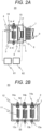
- FIG. 2A is a schematic cross-sectional view illustrating a temperature adjusting unit 20 of the automatic analyzer according to Embodiment 1 of the present invention.
- FIG. 2B is a cross-sectional view taken along line B-B of FIG. 2A .
- first reagent storage portion 1 a third reagent storage portion 11, and a fifth reagent storage portion 55 are not illustrated in cross section for convenience of illustration.
- the fourth reagent storage portion 12 functions as a buffer portion formed by a slightly thick straight stainless steel pipe or the like and stores the reagent. Further, the fifth reagent storage portion 55 and a sixth reagent storage portion 56 are attached.
- the fifth reagent storage portion 55 is obtained by spirally shaping a pipe made of stainless steel or the like to store the reagent.
- the sixth reagent storage portion 56 functions as a buffer portion formed by a slightly thick straight stainless steel pipe or the like and stores the reagent.
- a through hole which is slightly larger than the outer shape of the spiral of the pipe of the first reagent storage portion 1 is provided in the metal block 3.
- the first reagent storage portion 1 and the second reagent storage portion 2 are inserted into the through hole and are fixed by pouring solder or the like around the through hole.
- the first reagent storage portion 1 may be inserted into a through hole formed in the metal block 3 in a state where a pipe is wound around an aluminum cylinder, and be fixed with solder.
- a tube connector 13a is attached to the inlet port of the pipe of the first reagent storage portion 1.
- the tube connector 13a is threaded to be connected to the tube 47 with a fitting for the tube.
- a tube connector 14a is attached to the outlet port of the second reagent storage portion 2.
- the tube connector 14a is threaded to be connected to the tube 47 with a fitting for the tube.
- the metal base 3 is surrounded by a heat insulator 10.
- the heat insulator 10 is formed of, for example, urethane foam or the like.
- Heat is emitted (radiated) from the surface of the Peltier element 5, which is opposite to the grease 16 side.
- the heat is transferred from the grease 17 and the fin base 6 to the fins 7 and radiated to the air flowing between the fins 7 by the fan 9.
- a method of controlling the current output of the Peltier element controller 61 for example, a method of controlling the on/off time ratio of the current, that is, the duty ratio, is performed based on the target temperature and the temperature detected by the temperature detector 4 at regular time intervals, by proportional-integration-differential control (PID control) at regular time intervals. At this time, the current in supplying the power is set to be constant.
- PID control proportional-integration-differential control
- a first reagent storage portion 100 configured by a meandering pipe is buried in a metal block 300, and tube connectors 130 and 140 are attached to both ends of the first reagent storage portion 100.
- another reagent storage portion similar to the first reagent storage portion 100 is formed.
- the periphery of the metal block 300 is insulated by a heat insulator 110.
- FIG. 5A is a diagram illustrating a temperature distribution of the reagent in a temperature adjusting unit having a structure of the example different from that according to the present invention illustrated in FIG. 4 .
- FIG. 5B is a diagram illustrating a temperature distribution of the reagent in the temperature adjusting unit 20 according to Embodiment 1 of the present invention.
- FIGS. 5A and 5B illustrate an example of the cooling operation in which the ambient temperature is high.
- the internal volume (first reagent storage volume) of the first reagent storage portion 1 located on the upstream side of the second reagent storage portion 2 is set to be larger than the one-time discharge amount of each of the syringe pumps 29, 30, and 31.
- the winding diameter of the spiral pipe of the third reagent storage portion 11 corresponding to the flow path may be set to be smaller than that of the first reagent storage portion 1 and the fifth reagent storage portion 55, so as to reduce the reagent storage volume in comparison to the first reagent storage portion 1 and the fifth reagent storage portion 55.
- the inner diameter of the pipe of the fourth reagent storage portion 12 may be set to reduce the reagent storage volume in comparison to the second reagent storage portion 2 and the sixth reagent storage portion 56.
- the same one as the first reagent storage portion 1 and the fifth reagent storage portion 55 may be used as the third reagent storage portion 11, and thus only the reagent storage volume of the fourth reagent storage portion 12 may be reduced in comparison to the second reagent storage portion 2 and the sixth reagent storage portion 56.
- a threshold value based on the amount of change in temperature per unit time by the second temperature detector 19 is set in the Peltier element controller 61.
- the third embodiment it is possible to obtain effects similar to those in Embodiments 1 and 2.
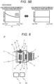
- FIG. 8 is a diagram illustrating a structure of a temperature adjusting unit 20 according to Embodiment 4 of the present invention.
- components common with those in Embodiment 1 described above are denoted by the same reference signs.
- the configuration of the applied automatic immunoassay analyzer is similar to the example illustrated in FIG. 1 , and thus illustrations and detailed description will be omitted.
- the temperature detector may also be disposed in either the vicinity of the outlet port of the first reagent storage portion 1 or the vicinity of the outlet port of the second reagent storage portion 2.
- FIG. 9 is a top view illustrating a temperature adjusting unit 20 according to Embodiment 5 of the present invention.
- FIG. 10 is a schematic cross-sectional view illustrating Embodiment 5.
- FIGS. 9 and 10 components common with those in Embodiment 1 described above are denoted by the same reference signs.
- the configuration of the applied automatic immunoassay analyzer is similar to the example illustrated in FIG. 1 , and thus illustrations and detailed description will be omitted. Note that, in FIG. 9 , illustration of the temperature detector 4 is omitted in order to simplify the illustration.
- the first reagent storage portion 1, the second reagent storage portion 2, the third reagent storage portion 11, the fourth reagent storage portion 12, the fifth reagent storage portion 55, and the sixth reagent storage portion 56 are arranged described above, and thus it is possible to further reduce the volume of the temperature adjusting unit 20 in addition to obtaining of effects similar to those in Embodiment 1.
- the present invention can be applied.
Landscapes
- Analytical Chemistry (AREA)
- Physics & Mathematics (AREA)
- Health & Medical Sciences (AREA)
- Life Sciences & Earth Sciences (AREA)
- Chemical & Material Sciences (AREA)
- Biochemistry (AREA)
- General Health & Medical Sciences (AREA)
- General Physics & Mathematics (AREA)
- Immunology (AREA)
- Pathology (AREA)
- Quality & Reliability (AREA)
- Engineering & Computer Science (AREA)
- Automatic Analysis And Handling Materials Therefor (AREA)
Applications Claiming Priority (2)
| Application Number | Priority Date | Filing Date | Title |
|---|---|---|---|
| JP2018168588A JP7028744B2 (ja) | 2018-09-10 | 2018-09-10 | 自動分析装置 |
| PCT/JP2019/024952 WO2020054172A1 (ja) | 2018-09-10 | 2019-06-24 | 自動分析装置 |
Publications (3)
| Publication Number | Publication Date |
|---|---|
| EP3822640A1 EP3822640A1 (en) | 2021-05-19 |
| EP3822640A4 EP3822640A4 (en) | 2022-04-06 |
| EP3822640B1 true EP3822640B1 (en) | 2025-04-16 |
Family
ID=69777730
Family Applications (1)
| Application Number | Title | Priority Date | Filing Date |
|---|---|---|---|
| EP19858729.7A Active EP3822640B1 (en) | 2018-09-10 | 2019-06-24 | Automated analyzer |
Country Status (5)
| Country | Link |
|---|---|
| US (1) | US11906534B2 (https=) |
| EP (1) | EP3822640B1 (https=) |
| JP (1) | JP7028744B2 (https=) |
| CN (1) | CN112513643B (https=) |
| WO (1) | WO2020054172A1 (https=) |
Families Citing this family (6)
| Publication number | Priority date | Publication date | Assignee | Title |
|---|---|---|---|---|
| EP4012419B1 (en) * | 2019-08-05 | 2025-12-10 | Hitachi High-Tech Corporation | Liquid dispensing device |
| WO2022210861A1 (ja) * | 2021-03-31 | 2022-10-06 | 積水メディカル株式会社 | 自動分析装置の温調システム |
| WO2023053691A1 (ja) * | 2021-09-30 | 2023-04-06 | 株式会社日立ハイテク | 自動分析装置 |
| WO2023127878A1 (ja) * | 2021-12-28 | 2023-07-06 | 積水メディカル株式会社 | 自動分析装置及び自動分析装置の試薬分注方法 |
| JP2024030088A (ja) * | 2022-08-23 | 2024-03-07 | 株式会社日立ハイテク | 自動分析装置 |
| EP4600653A1 (en) * | 2022-10-06 | 2025-08-13 | Hitachi High-Tech Corporation | Automated analyzing device, and method for operating automated analyzing device |
Family Cites Families (15)
| Publication number | Priority date | Publication date | Assignee | Title |
|---|---|---|---|---|
| JPS63205567A (ja) * | 1987-02-20 | 1988-08-25 | Nittec Co Ltd | 試薬用ピペツト装置 |
| CA2058648C (en) * | 1991-01-26 | 2003-02-18 | Manfred Geib | Pipette tube |
| CN101268371B (zh) * | 2005-09-05 | 2013-06-12 | 环球生物研究株式会社 | 各种物质保持体、各种物质保持体处理装置及其处理方法 |
| JP2007151696A (ja) * | 2005-12-02 | 2007-06-21 | Kazuyuki Fukui | 液体温度調節機及び液体温度調節システム |
| CN101865912B (zh) * | 2009-04-14 | 2014-05-14 | 南京大学 | 快速的化学发光免疫检测系统及分析方法 |
| DE102009029305A1 (de) * | 2009-09-09 | 2011-03-10 | Endress + Hauser Conducta Gesellschaft für Mess- und Regeltechnik mbH + Co. KG | Analysegerät zur automatisierten Bestimmung einer Messgröße einer Flüssigkeitsprobe |
| JP5249988B2 (ja) * | 2010-05-07 | 2013-07-31 | 株式会社日立ハイテクノロジーズ | 核酸増幅装置及びそれを用いた核酸検査装置 |
| DE102011007011B4 (de) * | 2011-04-07 | 2024-02-01 | Endress+Hauser Conducta Gmbh+Co. Kg | Analysegerät zur automatisierten Bestimmung einer Messgröße einer Flüssigkeitsprobe und Verfahren zur Überwachung einer Messgröße |
| EP2860528B1 (en) * | 2012-06-11 | 2018-01-03 | Hitachi High-Technologies Corporation | Automatic analysis apparatus |
| US9835612B2 (en) * | 2012-12-26 | 2017-12-05 | Hitachi High-Technologies Corporation | Automatic analyzer |
| JP6442378B2 (ja) | 2015-07-23 | 2018-12-19 | 株式会社日立ハイテクノロジーズ | 自動分析装置 |
| CN205720261U (zh) * | 2016-05-12 | 2016-11-23 | 利多(香港)有限公司 | 用于分析仪的液体加热传输装置 |
| WO2018047545A1 (ja) | 2016-09-08 | 2018-03-15 | 株式会社 日立ハイテクノロジーズ | 自動分析装置 |
| CN106822956A (zh) * | 2017-03-30 | 2017-06-13 | 厦门和健卫生技术服务有限公司 | 温控雾化处理装置 |
| CN107238527A (zh) * | 2017-04-28 | 2017-10-10 | 东南大学 | 一种高温裂解式气相汞形态转化装置及方法 |
-
2018
- 2018-09-10 JP JP2018168588A patent/JP7028744B2/ja active Active
-
2019
- 2019-06-24 EP EP19858729.7A patent/EP3822640B1/en active Active
- 2019-06-24 WO PCT/JP2019/024952 patent/WO2020054172A1/ja not_active Ceased
- 2019-06-24 US US17/265,289 patent/US11906534B2/en active Active
- 2019-06-24 CN CN201980049599.9A patent/CN112513643B/zh active Active
Also Published As
| Publication number | Publication date |
|---|---|
| JP7028744B2 (ja) | 2022-03-02 |
| WO2020054172A1 (ja) | 2020-03-19 |
| US11906534B2 (en) | 2024-02-20 |
| US20210302457A1 (en) | 2021-09-30 |
| EP3822640A1 (en) | 2021-05-19 |
| EP3822640A4 (en) | 2022-04-06 |
| CN112513643B (zh) | 2024-05-24 |
| CN112513643A (zh) | 2021-03-16 |
| JP2020041875A (ja) | 2020-03-19 |
Similar Documents
| Publication | Publication Date | Title |
|---|---|---|
| EP3822640B1 (en) | Automated analyzer | |
| US11953508B2 (en) | Automatic analysis device | |
| US8465697B2 (en) | System and method for regulating flow in fluidic devices | |
| US11237182B2 (en) | Automatic analyzer | |
| EP3511720B1 (en) | Automatic analyzer | |
| EP3271074B1 (en) | Dispenser for an analyzer | |
| CN113865970B (zh) | 自动样品浓缩单元 | |
| WO2020250630A1 (ja) | 自動分析装置 | |
| US8648316B2 (en) | Apparatus for cooling samples during ion beam preparation | |
| US9423803B2 (en) | Methods, systems, and apparatus providing temperature-controlled process fluid | |
| US20190030456A1 (en) | Pre-heater assembly with moderately thermally conductive capillary surrounding | |
| US20240053371A1 (en) | Heated degassing dispenser and methods | |
| EP4579242A1 (en) | Automatic analysis device | |
| EP4675280A1 (en) | Liquid storage device | |
| US20240310393A1 (en) | Automated analysis device | |
| EP4205854A1 (en) | Systems and methods for probe tip heating | |
| US20200209199A1 (en) | Supercritical fluid apparatus | |
| EP2040136A1 (en) | Temperature regulating device and method | |
| JP2025522966A (ja) | 分析機器の試料供給システム | |
| CN113874723A (zh) | 超临界流体装置用流动相调温装置及超临界流体装置 |
Legal Events
| Date | Code | Title | Description |
|---|---|---|---|
| STAA | Information on the status of an ep patent application or granted ep patent |
Free format text: STATUS: THE INTERNATIONAL PUBLICATION HAS BEEN MADE |
|
| PUAI | Public reference made under article 153(3) epc to a published international application that has entered the european phase |
Free format text: ORIGINAL CODE: 0009012 |
|
| STAA | Information on the status of an ep patent application or granted ep patent |
Free format text: STATUS: REQUEST FOR EXAMINATION WAS MADE |
|
| 17P | Request for examination filed |
Effective date: 20210209 |
|
| AK | Designated contracting states |
Kind code of ref document: A1 Designated state(s): AL AT BE BG CH CY CZ DE DK EE ES FI FR GB GR HR HU IE IS IT LI LT LU LV MC MK MT NL NO PL PT RO RS SE SI SK SM TR |
|
| RIN1 | Information on inventor provided before grant (corrected) |
Inventor name: FUNAKOSHI SUNAO Inventor name: OKUSA TAKENORI Inventor name: ISOSHIMA NOBUYUKI Inventor name: YOKOYAMA KOKI |
|
| RIN1 | Information on inventor provided before grant (corrected) |
Inventor name: YOKOYAMA KOKI Inventor name: ISOSHIMA NOBUYUKI Inventor name: OKUSA, TAKENORI Inventor name: FUNAKOSHI, SUNAO |
|
| DAV | Request for validation of the european patent (deleted) | ||
| DAX | Request for extension of the european patent (deleted) | ||
| A4 | Supplementary search report drawn up and despatched |
Effective date: 20220309 |
|
| RIC1 | Information provided on ipc code assigned before grant |
Ipc: G01N 35/00 20060101AFI20220303BHEP |
|
| STAA | Information on the status of an ep patent application or granted ep patent |
Free format text: STATUS: EXAMINATION IS IN PROGRESS |
|
| 17Q | First examination report despatched |
Effective date: 20230920 |
|
| GRAP | Despatch of communication of intention to grant a patent |
Free format text: ORIGINAL CODE: EPIDOSNIGR1 |
|
| STAA | Information on the status of an ep patent application or granted ep patent |
Free format text: STATUS: GRANT OF PATENT IS INTENDED |
|
| INTG | Intention to grant announced |
Effective date: 20250127 |
|
| GRAS | Grant fee paid |
Free format text: ORIGINAL CODE: EPIDOSNIGR3 |
|
| GRAA | (expected) grant |
Free format text: ORIGINAL CODE: 0009210 |
|
| STAA | Information on the status of an ep patent application or granted ep patent |
Free format text: STATUS: THE PATENT HAS BEEN GRANTED |
|
| AK | Designated contracting states |
Kind code of ref document: B1 Designated state(s): AL AT BE BG CH CY CZ DE DK EE ES FI FR GB GR HR HU IE IS IT LI LT LU LV MC MK MT NL NO PL PT RO RS SE SI SK SM TR |
|
| REG | Reference to a national code |
Ref country code: GB Ref legal event code: FG4D |
|
| REG | Reference to a national code |
Ref country code: CH Ref legal event code: EP Ref country code: DE Ref legal event code: R096 Ref document number: 602019068819 Country of ref document: DE |
|
| REG | Reference to a national code |
Ref country code: IE Ref legal event code: FG4D |
|
| PGFP | Annual fee paid to national office [announced via postgrant information from national office to epo] |
Ref country code: DE Payment date: 20250617 Year of fee payment: 7 |
|
| PGFP | Annual fee paid to national office [announced via postgrant information from national office to epo] |
Ref country code: FR Payment date: 20250624 Year of fee payment: 7 |
|
| REG | Reference to a national code |
Ref country code: NL Ref legal event code: MP Effective date: 20250416 |
|
| PG25 | Lapsed in a contracting state [announced via postgrant information from national office to epo] |
Ref country code: NL Free format text: LAPSE BECAUSE OF FAILURE TO SUBMIT A TRANSLATION OF THE DESCRIPTION OR TO PAY THE FEE WITHIN THE PRESCRIBED TIME-LIMIT Effective date: 20250416 |
|
| REG | Reference to a national code |
Ref country code: AT Ref legal event code: MK05 Ref document number: 1786039 Country of ref document: AT Kind code of ref document: T Effective date: 20250416 |
|
| PG25 | Lapsed in a contracting state [announced via postgrant information from national office to epo] |
Ref country code: PT Free format text: LAPSE BECAUSE OF FAILURE TO SUBMIT A TRANSLATION OF THE DESCRIPTION OR TO PAY THE FEE WITHIN THE PRESCRIBED TIME-LIMIT Effective date: 20250818 Ref country code: ES Free format text: LAPSE BECAUSE OF FAILURE TO SUBMIT A TRANSLATION OF THE DESCRIPTION OR TO PAY THE FEE WITHIN THE PRESCRIBED TIME-LIMIT Effective date: 20250416 Ref country code: FI Free format text: LAPSE BECAUSE OF FAILURE TO SUBMIT A TRANSLATION OF THE DESCRIPTION OR TO PAY THE FEE WITHIN THE PRESCRIBED TIME-LIMIT Effective date: 20250416 |
|
| REG | Reference to a national code |
Ref country code: LT Ref legal event code: MG9D |
|
| PG25 | Lapsed in a contracting state [announced via postgrant information from national office to epo] |
Ref country code: GR Free format text: LAPSE BECAUSE OF FAILURE TO SUBMIT A TRANSLATION OF THE DESCRIPTION OR TO PAY THE FEE WITHIN THE PRESCRIBED TIME-LIMIT Effective date: 20250717 Ref country code: NO Free format text: LAPSE BECAUSE OF FAILURE TO SUBMIT A TRANSLATION OF THE DESCRIPTION OR TO PAY THE FEE WITHIN THE PRESCRIBED TIME-LIMIT Effective date: 20250716 |
|
| PG25 | Lapsed in a contracting state [announced via postgrant information from national office to epo] |
Ref country code: PL Free format text: LAPSE BECAUSE OF FAILURE TO SUBMIT A TRANSLATION OF THE DESCRIPTION OR TO PAY THE FEE WITHIN THE PRESCRIBED TIME-LIMIT Effective date: 20250416 |
|
| PG25 | Lapsed in a contracting state [announced via postgrant information from national office to epo] |
Ref country code: BG Free format text: LAPSE BECAUSE OF FAILURE TO SUBMIT A TRANSLATION OF THE DESCRIPTION OR TO PAY THE FEE WITHIN THE PRESCRIBED TIME-LIMIT Effective date: 20250416 |
|
| PG25 | Lapsed in a contracting state [announced via postgrant information from national office to epo] |
Ref country code: HR Free format text: LAPSE BECAUSE OF FAILURE TO SUBMIT A TRANSLATION OF THE DESCRIPTION OR TO PAY THE FEE WITHIN THE PRESCRIBED TIME-LIMIT Effective date: 20250416 |
|
| PG25 | Lapsed in a contracting state [announced via postgrant information from national office to epo] |
Ref country code: AT Free format text: LAPSE BECAUSE OF FAILURE TO SUBMIT A TRANSLATION OF THE DESCRIPTION OR TO PAY THE FEE WITHIN THE PRESCRIBED TIME-LIMIT Effective date: 20250416 |
|
| PG25 | Lapsed in a contracting state [announced via postgrant information from national office to epo] |
Ref country code: RS Free format text: LAPSE BECAUSE OF FAILURE TO SUBMIT A TRANSLATION OF THE DESCRIPTION OR TO PAY THE FEE WITHIN THE PRESCRIBED TIME-LIMIT Effective date: 20250716 |
|
| PG25 | Lapsed in a contracting state [announced via postgrant information from national office to epo] |
Ref country code: IS Free format text: LAPSE BECAUSE OF FAILURE TO SUBMIT A TRANSLATION OF THE DESCRIPTION OR TO PAY THE FEE WITHIN THE PRESCRIBED TIME-LIMIT Effective date: 20250816 |
|
| PG25 | Lapsed in a contracting state [announced via postgrant information from national office to epo] |
Ref country code: LV Free format text: LAPSE BECAUSE OF FAILURE TO SUBMIT A TRANSLATION OF THE DESCRIPTION OR TO PAY THE FEE WITHIN THE PRESCRIBED TIME-LIMIT Effective date: 20250416 |
|
| PG25 | Lapsed in a contracting state [announced via postgrant information from national office to epo] |
Ref country code: DK Free format text: LAPSE BECAUSE OF FAILURE TO SUBMIT A TRANSLATION OF THE DESCRIPTION OR TO PAY THE FEE WITHIN THE PRESCRIBED TIME-LIMIT Effective date: 20250416 Ref country code: SM Free format text: LAPSE BECAUSE OF FAILURE TO SUBMIT A TRANSLATION OF THE DESCRIPTION OR TO PAY THE FEE WITHIN THE PRESCRIBED TIME-LIMIT Effective date: 20250416 |
|
| REG | Reference to a national code |
Ref country code: DE Ref legal event code: R097 Ref document number: 602019068819 Country of ref document: DE |
|
| PG25 | Lapsed in a contracting state [announced via postgrant information from national office to epo] |
Ref country code: CZ Free format text: LAPSE BECAUSE OF FAILURE TO SUBMIT A TRANSLATION OF THE DESCRIPTION OR TO PAY THE FEE WITHIN THE PRESCRIBED TIME-LIMIT Effective date: 20250416 |
|
| PG25 | Lapsed in a contracting state [announced via postgrant information from national office to epo] |
Ref country code: EE Free format text: LAPSE BECAUSE OF FAILURE TO SUBMIT A TRANSLATION OF THE DESCRIPTION OR TO PAY THE FEE WITHIN THE PRESCRIBED TIME-LIMIT Effective date: 20250416 |
|
| PG25 | Lapsed in a contracting state [announced via postgrant information from national office to epo] |
Ref country code: RO Free format text: LAPSE BECAUSE OF FAILURE TO SUBMIT A TRANSLATION OF THE DESCRIPTION OR TO PAY THE FEE WITHIN THE PRESCRIBED TIME-LIMIT Effective date: 20250416 Ref country code: SK Free format text: LAPSE BECAUSE OF FAILURE TO SUBMIT A TRANSLATION OF THE DESCRIPTION OR TO PAY THE FEE WITHIN THE PRESCRIBED TIME-LIMIT Effective date: 20250416 |
|
| REG | Reference to a national code |
Ref country code: CH Ref legal event code: H13 Free format text: ST27 STATUS EVENT CODE: U-0-0-H10-H13 (AS PROVIDED BY THE NATIONAL OFFICE) Effective date: 20260127 |
|
| PG25 | Lapsed in a contracting state [announced via postgrant information from national office to epo] |
Ref country code: IT Free format text: LAPSE BECAUSE OF FAILURE TO SUBMIT A TRANSLATION OF THE DESCRIPTION OR TO PAY THE FEE WITHIN THE PRESCRIBED TIME-LIMIT Effective date: 20250416 |
|
| PG25 | Lapsed in a contracting state [announced via postgrant information from national office to epo] |
Ref country code: MC Free format text: LAPSE BECAUSE OF FAILURE TO SUBMIT A TRANSLATION OF THE DESCRIPTION OR TO PAY THE FEE WITHIN THE PRESCRIBED TIME-LIMIT Effective date: 20250416 |
|
| PG25 | Lapsed in a contracting state [announced via postgrant information from national office to epo] |
Ref country code: LU Free format text: LAPSE BECAUSE OF NON-PAYMENT OF DUE FEES Effective date: 20250624 |
|
| PLBE | No opposition filed within time limit |
Free format text: ORIGINAL CODE: 0009261 |
|
| STAA | Information on the status of an ep patent application or granted ep patent |
Free format text: STATUS: NO OPPOSITION FILED WITHIN TIME LIMIT |
|
| REG | Reference to a national code |
Ref country code: CH Ref legal event code: L10 Free format text: ST27 STATUS EVENT CODE: U-0-0-L10-L00 (AS PROVIDED BY THE NATIONAL OFFICE) Effective date: 20260225 |
|
| REG | Reference to a national code |
Ref country code: BE Ref legal event code: MM Effective date: 20250630 |
|
| 26N | No opposition filed |
Effective date: 20260119 |
|
| GBPC | Gb: european patent ceased through non-payment of renewal fee |
Effective date: 20250716 |
|
| PG25 | Lapsed in a contracting state [announced via postgrant information from national office to epo] |
Ref country code: GB Free format text: LAPSE BECAUSE OF NON-PAYMENT OF DUE FEES Effective date: 20250716 |
|
| PG25 | Lapsed in a contracting state [announced via postgrant information from national office to epo] |
Ref country code: IE Free format text: LAPSE BECAUSE OF NON-PAYMENT OF DUE FEES Effective date: 20250624 |
|
| PG25 | Lapsed in a contracting state [announced via postgrant information from national office to epo] |
Ref country code: BE Free format text: LAPSE BECAUSE OF NON-PAYMENT OF DUE FEES Effective date: 20250630 |
|
| PG25 | Lapsed in a contracting state [announced via postgrant information from national office to epo] |
Ref country code: CH Free format text: LAPSE BECAUSE OF NON-PAYMENT OF DUE FEES Effective date: 20250630 |