EP3822611A1 - High-temperature and high-pressure hard rock true triaxial multifunctional shear test device and method - Google Patents
High-temperature and high-pressure hard rock true triaxial multifunctional shear test device and method Download PDFInfo
- Publication number
- EP3822611A1 EP3822611A1 EP19925559.7A EP19925559A EP3822611A1 EP 3822611 A1 EP3822611 A1 EP 3822611A1 EP 19925559 A EP19925559 A EP 19925559A EP 3822611 A1 EP3822611 A1 EP 3822611A1
- Authority
- EP
- European Patent Office
- Prior art keywords
- oil cylinder
- loading oil
- lateral
- normal
- tangential
- Prior art date
- Legal status (The legal status is an assumption and is not a legal conclusion. Google has not performed a legal analysis and makes no representation as to the accuracy of the status listed.)
- Granted
Links
Images



Classifications
-
- G—PHYSICS
- G01—MEASURING; TESTING
- G01N—INVESTIGATING OR ANALYSING MATERIALS BY DETERMINING THEIR CHEMICAL OR PHYSICAL PROPERTIES
- G01N3/00—Investigating strength properties of solid materials by application of mechanical stress
- G01N3/24—Investigating strength properties of solid materials by application of mechanical stress by applying steady shearing forces
-
- G—PHYSICS
- G01—MEASURING; TESTING
- G01N—INVESTIGATING OR ANALYSING MATERIALS BY DETERMINING THEIR CHEMICAL OR PHYSICAL PROPERTIES
- G01N3/00—Investigating strength properties of solid materials by application of mechanical stress
- G01N3/08—Investigating strength properties of solid materials by application of mechanical stress by applying steady tensile or compressive forces
- G01N3/10—Investigating strength properties of solid materials by application of mechanical stress by applying steady tensile or compressive forces generated by pneumatic or hydraulic pressure
-
- G—PHYSICS
- G01—MEASURING; TESTING
- G01N—INVESTIGATING OR ANALYSING MATERIALS BY DETERMINING THEIR CHEMICAL OR PHYSICAL PROPERTIES
- G01N3/00—Investigating strength properties of solid materials by application of mechanical stress
- G01N3/08—Investigating strength properties of solid materials by application of mechanical stress by applying steady tensile or compressive forces
- G01N3/10—Investigating strength properties of solid materials by application of mechanical stress by applying steady tensile or compressive forces generated by pneumatic or hydraulic pressure
- G01N3/12—Pressure testing
-
- G—PHYSICS
- G01—MEASURING; TESTING
- G01N—INVESTIGATING OR ANALYSING MATERIALS BY DETERMINING THEIR CHEMICAL OR PHYSICAL PROPERTIES
- G01N3/00—Investigating strength properties of solid materials by application of mechanical stress
- G01N3/08—Investigating strength properties of solid materials by application of mechanical stress by applying steady tensile or compressive forces
- G01N3/18—Performing tests at high or low temperatures
-
- G—PHYSICS
- G01—MEASURING; TESTING
- G01N—INVESTIGATING OR ANALYSING MATERIALS BY DETERMINING THEIR CHEMICAL OR PHYSICAL PROPERTIES
- G01N2203/00—Investigating strength properties of solid materials by application of mechanical stress
- G01N2203/0001—Type of application of the stress
- G01N2203/0003—Steady
-
- G—PHYSICS
- G01—MEASURING; TESTING
- G01N—INVESTIGATING OR ANALYSING MATERIALS BY DETERMINING THEIR CHEMICAL OR PHYSICAL PROPERTIES
- G01N2203/00—Investigating strength properties of solid materials by application of mechanical stress
- G01N2203/0014—Type of force applied
- G01N2203/0025—Shearing
-
- G—PHYSICS
- G01—MEASURING; TESTING
- G01N—INVESTIGATING OR ANALYSING MATERIALS BY DETERMINING THEIR CHEMICAL OR PHYSICAL PROPERTIES
- G01N2203/00—Investigating strength properties of solid materials by application of mechanical stress
- G01N2203/003—Generation of the force
- G01N2203/0042—Pneumatic or hydraulic means
- G01N2203/0048—Hydraulic means
-
- G—PHYSICS
- G01—MEASURING; TESTING
- G01N—INVESTIGATING OR ANALYSING MATERIALS BY DETERMINING THEIR CHEMICAL OR PHYSICAL PROPERTIES
- G01N2203/00—Investigating strength properties of solid materials by application of mechanical stress
- G01N2203/02—Details not specific for a particular testing method
- G01N2203/022—Environment of the test
- G01N2203/0222—Temperature
- G01N2203/0226—High temperature; Heating means
-
- G—PHYSICS
- G01—MEASURING; TESTING
- G01N—INVESTIGATING OR ANALYSING MATERIALS BY DETERMINING THEIR CHEMICAL OR PHYSICAL PROPERTIES
- G01N2203/00—Investigating strength properties of solid materials by application of mechanical stress
- G01N2203/02—Details not specific for a particular testing method
- G01N2203/022—Environment of the test
- G01N2203/023—Pressure
- G01N2203/0232—High pressure
-
- G—PHYSICS
- G01—MEASURING; TESTING
- G01N—INVESTIGATING OR ANALYSING MATERIALS BY DETERMINING THEIR CHEMICAL OR PHYSICAL PROPERTIES
- G01N2203/00—Investigating strength properties of solid materials by application of mechanical stress
- G01N2203/02—Details not specific for a particular testing method
- G01N2203/025—Geometry of the test
- G01N2203/0256—Triaxial, i.e. the forces being applied along three normal axes of the specimen
Definitions
- the present invention relates to a rock loading test device and method, in particular to a multi-functional true triaxial shear test device and method for hard rocks with high temperature and high pressure.
- rock mass are affected by true triaxial stress ( ⁇ > ⁇ p > ⁇ n ), and in general, rock mass are easier to failure when the structural surfaces are perpendicular to the minimum principal stress direction ( ⁇ n ).
- the rock samples are divided into an upper part and a lower part along the center line of the shear direction. During the test process, only half of the cross-sections of the rock samples in the shear direction are under stress, and the other half of the cross-sections are in the free state.
- the shear test method includes a constant normal stress or constant normal stiffness test under the quasi-static-state and a constant normal stress shear test under the long-term creep loading. But atime-dependent shear test under constant normal stiffness has not been realized by test equipment.
- conventional shear test machines mostly include a stand column type and a pull rod type framework, the framework is low in stiffness.
- the framework easily accumulates enough elastic strain energy in the test, and post-peak elastic strain energy is released. As a result, the rock is prone to sudden brittle failure in the post-peak curve.
- an existing true triaxial equipment hydraulic cylinder can only provide a constant force in each direction, and cannot perform rock cross-section full-coverage loading in a shear process.
- a primary objective of the present invention is to provide a multi-functional true triaxial shear test device and method for hard rocks with high temperature and high pressure. Up to 1200MPa of high stress can be applied, the highest temperature can reach 250 °C, a quasi-static-state time-dependent shear test for hard rocks at high temperature and high pressure under true triaxialconstant normal stress/stiffness is realized for the first time, the stiffness of the device is guaranteed, and at the same time, loading is applied onto the full cross sections of the rock samples; and by a method of performing heating in a high-temperature tank and lowering temperature at the front end of an actuator, a hard rock shear failure process under true high-temperature and high three-dimensional stress condition is carried out in laboratory.
- the annular framework is fixedly mounted on an upper surface of the annular framework support platform through bolts
- the horizontal support platform is arranged at a rear end of the annular framework support platform
- the horizontal support platform and the annular framework support platform are both fixedly mounted on a ground.
- lateral auxiliary push-and-pull framework is arranged on the horizontal support platform through a guide rail and a sliding block.
- the left-end combination tangential loading oil cylinder is mounted in a left-end through hole of the annular framework
- the right-end combination tangential loading oil cylinder is mounted in a right-end through hole of the annular framework
- the upper normal loading oil cylinder is arranged in an upper-end through hole of the annular framework
- the lower normal loading oil cylinder is arranged in a lower-end through hole of the annular framework.
- front-end combination lateral loading oil cylinder is mounted in a front-end through hole of the lateral auxiliary push-and-pull framework
- rear-end combination lateral loading oil cylinder is arranged in a rear-end through hole of the lateral auxiliary push-and-pull framework.
- a plurality of displacement sensors are respectively arranged at a rear end of the left-end combination tangential loading oil cylinder, a rear end of the right-end combination tangential loading oil cylinder, a rear end of the front-end combination lateral loading oil cylinder, a rear end of the rear-end combination lateral loading oil cylinder and a rear end of the upper normal loading oil cylinder.
- left-end combination tangential loading oil cylinder the right-end combination tangential loading oil cylinder, the front-end combination lateral loading oil cylinder, the rear-end combination lateral loading oil cylinder, the upper normal loading oil cylinder and the lower normal loading oil cylinder are respectively connected with the hydraulic system.
- test chamber is mounted in a rectangular through hole of the lateral auxiliary push-and-pull framework, a shear box is placed in the test chamber, and rock samples are placed in the shear box.
- the left-end combination tangential loading oil cylinder comprises a left tangential upper loading oil cylinder and a left tangential lower loading oil cylinder, and the left tangential lower loading oil cylinder is coaxially mounted on the left tangential upper loading oil cylinder;
- the right-end combination tangential loading oil cylinder comprises a right tangential upper loading oil cylinder and a right tangential lower loading oil cylinder, and the right tangential upper loading oil cylinder is coaxially mounted on the right tangential lower loading oil cylinder;
- the left tangential upper loading oil cylinder and the right tangential lower loading oil cylinder are the same in structure, and both consist of a first sealing cover, a first piston, a first connecting plate, a first force measuring sensor and a first force transmitting plate; wherein each first piston is arranged in an inner cavity of the corresponding first sealing cover, each first piston is connected with one end of the corresponding first connecting plate, the other end of the first connecting plate is connected with one end of the corresponding first
- the front-end combination lateral loading oil cylinder comprises a front lateral upper loading oil cylinder and a front lateral lower loading oil cylinder, and the front lateral lower loading oil cylinder is coaxially mounted at an inner cavity of the front lateral upper loading oil cylinder;
- the rear-end combination lateral loading oil cylinder comprises a rear lateral upper loading oil cylinder and a rear lateral lower loading oil cylinder, and the rear lateral lower loading oil cylinder is coaxially mounted at an inner cavity of the rear lateral upper loading oil cylinder;
- the front lateral upper loading oil cylinder and the rear lateral upper loading oil cylinder are the same in structure and both consist of an upper lateral sealing cover, an upper lateral counterforce cylinder barrel, an upper lateral piston, an upper lateral sealing flange, an upper lateral force measuring sensor and an upper lateral force transmitting plate; wherein each upper lateral piston is coaxially mounted at a first boss of the corresponding upper lateral sealing cover, each upper lateral counterforce cylinder barrel is coaxially mounted at
- the upper normal loading oil cylinder consists of an upper normal sealing cover, an upper normal cylinder barrel, an upper normal piston, an upper normal connecting plate, an upper normal force measuring sensor and an upper normal force transmitting plate and wherein a flange end of the upper normal sealing cover is connected with a flange end of the upper normal cylinder barrel, the upper normal piston is arranged on an inner wall of the upper normal cylinder barrel, a part of the upper normal piston extends out of the upper normal cylinder barrel, and is connected with one end of the upper normal connecting plate, the other end of the upper normal connecting plate is connected with one end of the upper normal force measuring sensor, and the other end of the upper normal force measuring sensor is connected with the upper normal force transmitting plate.
- the lower normal loading oil cylinder consists of a lower normal sealing plate, a lower normal piston, a lower normal sealing flange, a lower normal connecting plate, a lower normal force measuring sensor and a lower normal force transmitting plate; and wherein the lower normal piston is arranged in an inner cavity of the lower normal sealing plate, a flange end of the lower normal sealing plate is connected with the lower normal sealing flange, a part of the lower piston extends out of the lower normal sealing flange, and is connected with one end of the lower normal connecting plate, the other end of the lower normal connecting plate is connected with one end of the lower normal force measuring sensor, and the other end of the lower normal force measuring sensor is connected with the lower normal force transmitting plate.
- two penetrating cooling water through holes are formed in a front end of a first force transmitting plate of the left-end combination tangential loading oil cylinder, two penetrating cooling water through holes are formed in a front end of a first force transmitting plate of the right-end combination tangential loading oil cylinder, two penetrating cooling water through holes are formed in a front end of an upper lateral force transmitting plate of the front-end combination lateral loading oil cylinder, two penetrating cooling water through holes are formed in a front end of an upper lateral force transmitting plate of the rear-end combination lateral loading oil cylinder, two penetrating cooling water through holes are formed in a front end of a lower lateral force transmitting plate of the front-end combination lateral loading oil cylinder, two penetrating cooling water through holes are formed in a front end of a lower lateral force transmitting plate of the rear-end combination lateral loading oil cylinder, two penetrating cooling water through holes are formed in a front end of an upper normal force
- the hydraulic system comprises a first hydraulic station, a second hydraulic station, a third hydraulic station, a first energy accumulator, a second energy accumulator, a third energy accumulator and a plurality of servo valves; wherein the first hydraulic station is connected with the first energy accumulator through a high pressure resistant oil pipe, and the first energy accumulator is connected with a left tangential upper loading oil cylinder, a left tangential lower loading oil cylinder and the upper normal loading oil cylinder through the high pressure resistant oil pipe and the servo valves; wherein the second hydraulic station is connected with the second energy accumulator through a high pressure resistant oil pipe, and the second energy accumulator is connected with a right tangential upper loading oil cylinder, a right tangential lower loading oil cylinder and the lower normal loading oil cylinder through the high pressure resistant oil pipe and the servo valves; wherein the third hydraulic station is connected with the third energy accumulator through a high pressure resistant oil pipe, the third energy accumulator is connected with
- the hydraulic pumps are connected with a servo driver and cooling water in series, firstly, when pressure in the oil cylinders is reduced, the servo driver feeds back the pressure in the oil cylinders to the hydraulic pumps in real time, so that the hydraulic pumps work, the pressure in the oil cylinders is complemented, or else, the hydraulic pumps stop working.
- the energy accumulators can complement pressure for the oil cylinders continuously. In this manner, continuous temperature rise caused by work of the hydraulic pumps can be reduced, and completion of the long-time constant normal stiffness test can be guaranteed.
- the test chamber is a thermostatic chamber, and the rock samples in the shear box are heated in a ceramic radiation heating manner.
- a multi-functional true triaxial shear test method for hard rocks with high temperature and high pressure for the device comprising the following steps:
- the multi-functional true triaxial shear test device for hard rocks with high temperature and high pressure has the beneficial effects: Compared with the prior art, the multi-functional true triaxial shear test device for hard rocks with high temperature and high pressure has the advantages that a hard rock shear test under the true triaxial condition is realized for the first time.
- a loading framework and the oil cylinders having the brand-new structures are designed, the integral stiffness of the device is improved, and besides, a total cross section stress covering loading manner of the rock samples in the true triaxial shear process is guaranteed.
- a temperature lowering manner of the front ends of the oil cylinders the situation that high temperature which is as high as 300 °C does not enable the temperature of hydraulic oil in the oil cylinders to rise to affect normal motion of the actuator can be guaranteed.
- a multi-functional true triaxial shear test device for hard rocks with high temperature and high pressure comprises a hydraulic system, a left-end combination tangential loading oil cylinder, a right-end combination tangential loading oil cylinder, a front-end combination lateral loading oil cylinder, a rear-end combination lateral loading oil cylinder, an upper normal loading oil cylinder3, a lower normal loading oil cylinder 6, an annular framework 11, a lateral auxiliary push-and-pull framework 12, an annular framework support platform 13, a horizontal support platform 14 and a test chamber 16.As shown in Figs.
- the annular framework 11 is fixedly mounted on an upper surface of the annular framework support platform 13 through bolts
- the horizontal support platform 14 is arranged at a rear end of the annular framework support platform 13
- the horizontal support platform 14 and the annular framework support platform 13 are both fixedly mounted on the ground.
- the lateral auxiliary push-and-pull framework 12 is arranged on the horizontal support platform 14 through a guide rail 15 and a sliding block.
- the left-end combination tangential loading oil cylinder is mounted in a left-end through hole of the annular framework 11
- the right-end combination tangential loading oil cylinder is mounted in a right-end through hole of the annular framework 11
- the upper normal loading oil cylinder 3 is arranged in an upper-end through hole of the annular framework 11
- the lower normal loading oil cylinder 6 is arranged in a lower-end through hole of the annular framework 11.
- the front-end combination lateral loading oil cylinder is mounted in a front-end through hole of the lateral auxiliary push-and-pull framework 12
- the rear-end combination lateral loading oil cylinder is arranged in a rear-end through hole of the lateral auxiliary push-and-pull framework 12.
- a plurality of displacement sensors 19 are respectively arranged at a rear end of the left-end combination tangential loading oil cylinder, a rear end of the right-end combination tangential loading oil cylinder, a rear end of the front-end combination lateral loading oil cylinder, a rear end of the rear-end combination lateral loading oil cylinder and a rear end of the upper normal loading oil cylinder 3, and the displacement sensors 19are connected with a computer (not shown). As shown in Figs.
- the left-end combination tangential loading oil cylinder, the right-end combination tangential loading oil cylinder, the front-end combination lateral loading oil cylinder, the rear-end combination lateral loading oil cylinder, the upper normal loading oil cylinder 3 and the lower normal loading oil cylinder 6 are all connected with the hydraulic system.
- the test chamber 16 is mounted in a rectangular through hole of the lateral auxiliary push-and-pull framework 12, a shear box 17 is placed in the test chamber 16, and rock samples 18 are placed in the shear box 17.
- the left-end combination tangential loading oil cylinder comprises a left tangential upper loading oil cylinder 1 and a left tangential lower loading oil cylinder 2, and the left tangential lower loading oil cylinder 2 is coaxially mounted on the left tangential upper loading oil cylinder 1.
- the right-end combination tangential loading oil cylinder comprises a right tangential upper loading oil cylinder 5 and a right tangential lower loading oil cylinder 4, and the right tangential upper loading oil cylinder 5 is coaxially mounted on the right tangential lower loading oil cylinder 4.As shown in Fig.
- the left tangential upper loading oil cylinder 1 and the right tangential lower loading oil cylinder 4 are the same in structure, and both consist of a first sealing cover 1-1, a first piston 1-2, a first connecting plate 1-3, a first force measuring sensor 1-4 and a first force transmitting plate 1-5.
- Each first piston 1-2 is arranged in an inner cavity of the corresponding first sealing cover 1-1, each first piston 1-2 is connected with one end of the corresponding first connecting plate 1-3, the other end of the first connecting plate 1-3 is connected with one end of the corresponding first force measuring sensor 1-4, and the other end of the first force measuring sensor 1-4 is connected with the corresponding first force transmitting plate 1-5.
- each second sealing cover 2-1 is coaxially mounted on an outer peripheral surface of the corresponding first piston 1-2, a boss at one end of each second sealing cover 2-1 extends into the inner cavity of the corresponding first sealing cover 1-1 to be in connection with the corresponding first sealing cover 1-1 in a sealed manner, each second piston 2-3 and the corresponding second counterforce cylinder barrel 2-2 are coaxially mounted at the other end of the corresponding second sealing cover 2-1, each second counterforce cylinder barrel 2-2 is coaxially mounted on an outer peripheral surface of the corresponding second piston 2-3 and is fixedly mounted on the corresponding second sealing cover 2-1 through bolts, an extending end of each second piston 2-3 is connected with one
- the front-end combination lateral loading oil cylinder comprises a front lateral upper loading oil cylinder 8 and a front lateral lower loading oil cylinder 7, and the front lateral lower loading oil cylinder 7 is coaxially mounted at an inner cavity of the front lateral upper loading oil cylinder 8.
- the rear-end combination lateral loading oil cylinder comprises a rear lateral upper loading oil cylinder 10 and a rear lateral lower loading oil cylinder 9, and the rear lateral lower loading oil cylinder 9 is coaxially mounted at an inner cavity of the rear lateral upper loading oil cylinder 10.
- Fig. 3 the front-end combination lateral loading oil cylinder comprises a front lateral upper loading oil cylinder 8 and a front lateral lower loading oil cylinder 7, and the front lateral lower loading oil cylinder 7 is coaxially mounted at an inner cavity of the front lateral upper loading oil cylinder 8.
- the rear-end combination lateral loading oil cylinder comprises a rear lateral upper loading oil cylinder 10 and a rear lateral lower loading oil cylinder 9, and the rear lateral lower loading oil cylinder 9
- the front lateral upper loading oil cylinder 8 and the rear lateral upper loading oil cylinder 10 are the same in structure and both consist of an upper lateral sealing cover 8-1, an upper lateral counterforce cylinder barrel 8-2, an upper lateral piston 8-3, an upper lateral sealing flange 8-4, an upper lateral force measuring sensor 8-5 and an upper lateral force transmitting plate 8-6.
- Each upper lateral piston 8-3 is coaxially mounted at a first boss of the corresponding upper lateral sealing cover 8-1
- each upper lateral counterforce cylinder barrel 8-2 is coaxially mounted at a second boss of the corresponding upper lateral sealing cover 8-1
- an inner surface of each upper lateral counterforce cylinder barrel 8-2 is in contact with an outer surface of the corresponding upper lateral piston 8-3
- each upper lateral piston 8-3 is connected with one end of the corresponding upper lateral sealing flange 8-4
- the other end of the upper lateral sealing flange 8-4 is connected with one end of the corresponding upper lateral force measuring sensor 8-5
- the other end of the upper lateral force measuring sensor 8-5 is connected with the corresponding upper lateral force transmitting plate 8-6.
- the front lateral lower loading oil cylinder 7 and the rear lateral lower loading oil cylinder 9 are the same in structure and both consist of a lower lateral sealing cover 7-1, a lower lateral piston 7-2, a lower lateral connecting plate 7-3, a lower lateral force measuring sensor 7-4 and a lower lateral force transmitting plate 7-5.
- each lower lateral sealing cover 7-1 extends into an inner cavity of the corresponding upper lateral sealing cover 8-1, a flange end of each lower lateral sealing cover 7-1 is fixedly mounted on the corresponding upper lateral sealing cover 8-1 through bolts, each lower lateral piston 7-2 is mounted at an inner cavity of the corresponding upper lateral sealing cover 8-1, each lower lateral piston 7-2 is located in a sealing cavity formed by the corresponding upper lateral sealing cover 8-1 and the corresponding lower lateral sealing cover 7-1, a part of each lower lateral piston 7-2 extends out of a boss in the corresponding upper lateral sealing cover 8-1, and is connected with one end of the corresponding lower lateral connecting plate 7-3, the other end of the lower lateral connecting plate 7-3 is connected with one end of the corresponding lower lateral force measuring sensor 7-4, the other end of the lower lateral force measuring sensor 7-4 is connected with the corresponding lower lateral force transmitting plate 7-5, the lower lateral force transmitting plate 7-5 penetrates through the upper lateral force transmitting plate 8
- the upper normal loading oil cylinder 3 consists of an upper normal sealing cover 3-1, an upper normal cylinder barrel 3-2, an upper normal piston 3-3, an upper normal connecting plate 3-4, an upper normal force measuring sensor 3-5 and an upper normal force transmitting plate 3-6.
- a flange end of the upper normal sealing cover 3-1 is connected with a flange end of the upper normal cylinder barrel 3-2
- the upper normal piston 3-3 is arranged on an inner wall of the upper normal cylinder barrel 3-2
- a part of the upper normal piston 3-3 extends out of the upper normal cylinder barrel 3-2 and is connected with one end of the upper normal connecting plate 3-4
- the other end of the upper normal connecting plate 3-4 is connected with one end of the upper normal force measuring sensor 3-5
- the other end of the upper normal force measuring sensor 3-5 is connected with the upper normal force transmitting plate 3-6
- each upper normal force measuring sensor 3-5 is connected with the computer.
- the lower normal loading oil cylinder 6 consists of a lower normal sealing plate 6-1, a lower normal piston 6-2, a lower normal sealing flange 6-3, a lower normal connecting plate 6-4, a lower normal force measuring sensor 6-5 and a lower normal force transmitting plate 6-6, wherein the lower normal piston 6-2 is arranged in an inner cavity of the lower normal sealing plate 6-1, a flange end of the lower normal sealing plate 6-1 is connected with the lower normal sealing flange 6-3, a part of the lower normal piston 6-2 extends out of the lower normal sealing flange 6-3 and is connected with one end of the lower normal connecting plate, the other end of the lower normal connecting plate 6-4 is connected with one end of the lower normal force measuring sensor 6-5, the other end of the lower normal force measuring sensor 6-5 is connected with the lower normal force transmitting plate 6-6, and each lower normal force measuring sensor 6-5 is connected with the computer.
- Two penetrating cooling water through holes are formed in a front end of the first force transmitting plates 1-5 of the left-end combination tangential loading oil cylinder, two penetrating cooling water through holes are formed in a front end of the first force transmitting plates 1-5 of the right-end combination tangential loading oil cylinder, two penetrating cooling water through holes are formed in a front end of the upper lateral force transmitting plate 8-6 of the front-end combination lateral loading oil cylinder , two penetrating cooling water through holes are formed in a front end of the upper lateral force transmitting plate 8-6 of the rear-end combination lateral loading oil cylinder, two penetrating cooling water through holes are formed in a front end of the lower lateral force transmitting plate 7-5 of the front-end combination lateral loading oil cylinder, two penetrating cooling water through holes are formed in a front end of the lower lateral force transmitting plate 7-5 of the rear-end combination lateral loading oil cylinder, two penetrating cooling water through holes are formed in a front
- the hydraulic system comprises a first hydraulic station 22, a second hydraulic station 23, a third hydraulic station 24, a first energy accumulator 25, a second energy accumulator 26, a third energy accumulator 27 and a plurality of servo valves 21.
- the first hydraulic station 22 is connected with the first energy accumulator 25 through a high pressure resistant oil pipe
- the first energy accumulator 25 is connected with the left tangential upper loading oil cylinder 1, the left tangential lower loading oil cylinder 2 and the upper normal loading oil cylinder 3 through the high pressure resistant oil pipe and the servo valves 21.As shown in Fig.
- the second hydraulic station 23 is connected with the second energy accumulator 26 through a high pressure resistant oil pipe, and the second energy accumulator 26 is connected with the right tangential upper loading oil cylinder 5, the right tangential lower loading oil cylinder 4 and the lower normal loading oil cylinder 6 through the high pressure resistant oil pipe and the servo valves 21.
- the third hydraulic station 24 is connected with the third energy accumulator 27 through a high pressure resistant oil pipe, the third energy accumulator 27 is connected with the front lateral upper loading oil cylinder 8 and the front lateral lower loading oil cylinder 7 and the rear lateral upper loading oil cylinder10 and the rear lateral lower loading oil cylinder 9 through the high pressure resistant oil pipe and the servo valves 21.
- the first hydraulic station 22, the second hydraulic station 23 and the third hydraulic station 24 are the same in structure and all comprise a hydraulic pump and an oil tank, and an oil inlet of each hydraulic pump is connected with an oil outlet of the corresponding oil tank through the corresponding high pressure resistant oil pipe.
- the hydraulic pumps are connected with a servo driver and cooling water in series, and firstly, when pressure in the oil cylinders is reduced, the servo driver feeds back the pressure in the oil cylinders to the hydraulic pumps in real time, so that the hydraulic pumps work, the pressure in the oil cylinders is complemented, or else, the hydraulic pumps stop working.
- the energy accumulators can complement pressure for the oil cylinders continuously. In this manner, continuous temperature rise caused by work of the hydraulic pumps can be reduced, and completion of the long-time constant normal stiffness test can be guaranteed.
- the test chamber 16 is a thermostaticchamber, and the rock samples 18 in the shear box 17 are heated in a ceramic radiation heating manner.
- a multi-functional true triaxial shear test method for hard rocks with high temperature and high pressure for the device comprises the following steps:
Landscapes
- Physics & Mathematics (AREA)
- Health & Medical Sciences (AREA)
- Life Sciences & Earth Sciences (AREA)
- Chemical & Material Sciences (AREA)
- Analytical Chemistry (AREA)
- Biochemistry (AREA)
- General Health & Medical Sciences (AREA)
- General Physics & Mathematics (AREA)
- Immunology (AREA)
- Pathology (AREA)
- Investigating Strength Of Materials By Application Of Mechanical Stress (AREA)
Abstract
Description
- The present invention relates to a rock loading test device and method, in particular to a multi-functional true triaxial shear test device and method for hard rocks with high temperature and high pressure.
- The bearing capacity of rocks as a natural carrier of underground mining, deep-buried tunnels, nuclear waste disposal depots and the like directly affects the normal operation of engineering and is the important guarantee for personnel safety. Underground rock mass are not complete, and structural surfaces, faults and the like being low in bearing capacity exit to different extent. Under the action of high shear stress, the rock mass containing structural surfaces easily form engineering disasters of earthquakes, landslides, deep cracking, time delayed rockburst. Therefore, researching on failure mechanism of the hard rocks containing structural surfaces has important significance in understanding and preventing the occurrence of the engineering disasters.
- It is well known that the underground rock mass are affected by true triaxial stress (τ > σp > σn), and in general, rock mass are easier to failure when the structural surfaces are perpendicular to the minimum principal stress direction (σn). At present, mainly a conventional direct shearing method (τ>σn, σp=0) is used for the hard rock shear test, and used rock samples are generally cuboids. During a conventional direct shear test, the rock samples are divided into an upper part and a lower part along the center line of the shear direction. During the test process, only half of the cross-sections of the rock samples in the shear direction are under stress, and the other half of the cross-sections are in the free state. Moreover, the lateral stress (σp=0) is assumed to be the minimum principal stress. These do not conform to the three-dimensional stress state in which the underground rock mass containing structural surfaces are broken. In addition, the structural surfaces far away from the free surface of a tunnel are limited by the surrounding rock mass and are often under the condition of constant normal stiffness. At present, the shear test method includes a constant normal stress or constant normal stiffness test under the quasi-static-state and a constant normal stress shear test under the long-term creep loading. But atime-dependent shear test under constant normal stiffness has not been realized by test equipment. This is mainly because that the constant normal stiffness test needs a cooperative mode of a hydraulic oil pump and an electro-hydraulic servo valve, a normal piston is subjected to high-frequency adjustment and control, however, the temperature of an oil source is easy to raise in this manner, and the life of an oil source system is easy to reduce after long-time operation.
- In addition, as the depth of the underground rock mass engineering is deeper and deeper, temperature also plays a major role on rock failure. It is generally believed that for every 100 meters increase in depth, the temperature of the rock mass can increase by 3°C, and the temperature of the position being about 5000 meters underground reaches about 180 °C. Temperature is one of the most important factors affecting deformation and breaking of deep hard rocks.
- At present, conventional shear test machines mostly include a stand column type and a pull rod type framework, the framework is low in stiffness. The framework easily accumulates enough elastic strain energy in the test, and post-peak elastic strain energy is released. As a result, the rock is prone to sudden brittle failure in the post-peak curve. In addition, an existing true triaxial equipment hydraulic cylinder can only provide a constant force in each direction, and cannot perform rock cross-section full-coverage loading in a shear process.
- A primary objective of the present invention is to provide a multi-functional true triaxial shear test device and method for hard rocks with high temperature and high pressure. Up to 1200MPa of high stress can be applied, the highest temperature can reach 250 °C, a quasi-static-state time-dependent shear test for hard rocks at high temperature and high pressure under true triaxialconstant normal stress/stiffness is realized for the first time, the stiffness of the device is guaranteed, and at the same time, loading is applied onto the full cross sections of the rock samples; and by a method of performing heating in a high-temperature tank and lowering temperature at the front end of an actuator, a hard rock shear failure process under true high-temperature and high three-dimensional stress condition is carried out in laboratory.
- To achieve the above objectives, the present invention providesa multi-functional true triaxial shear test device for hard rocks with high temperature and high pressure comprises a hydraulic system, a left-end combination tangential loading oil cylinder, a right-end combination tangential loading oil cylinder, a front-end combination lateral loading oil cylinder, a rear-end combination lateral loading oil cylinder, an upper normal loading oil cylinder, a lower normal loading oil cylinder, an annular framework, a lateral auxiliary push-and-pull framework, an annular framework support platform, a horizontal support platform and a test chamber.
- Wherein the annular framework is fixedly mounted on an upper surface of the annular framework support platform through bolts, the horizontal support platform is arranged at a rear end of the annular framework support platform, and the horizontal support platform and the annular framework support platform are both fixedly mounted on a ground.
- Wherein the lateral auxiliary push-and-pull framework is arranged on the horizontal support platform through a guide rail and a sliding block.
- Wherein the left-end combination tangential loading oil cylinder is mounted in a left-end through hole of the annular framework, the right-end combination tangential loading oil cylinder is mounted in a right-end through hole of the annular framework, the upper normal loading oil cylinder is arranged in an upper-end through hole of the annular framework, and the lower normal loading oil cylinder is arranged in a lower-end through hole of the annular framework.
- Wherein the front-end combination lateral loading oil cylinder is mounted in a front-end through hole of the lateral auxiliary push-and-pull framework, and the rear-end combination lateral loading oil cylinder is arranged in a rear-end through hole of the lateral auxiliary push-and-pull framework.
- Wherein a plurality of displacement sensors are respectively arranged at a rear end of the left-end combination tangential loading oil cylinder, a rear end of the right-end combination tangential loading oil cylinder, a rear end of the front-end combination lateral loading oil cylinder, a rear end of the rear-end combination lateral loading oil cylinder and a rear end of the upper normal loading oil cylinder.
- Wherein the left-end combination tangential loading oil cylinder, the right-end combination tangential loading oil cylinder, the front-end combination lateral loading oil cylinder, the rear-end combination lateral loading oil cylinder, the upper normal loading oil cylinder and the lower normal loading oil cylinder are respectively connected with the hydraulic system.
- Wherein the test chamber is mounted in a rectangular through hole of the lateral auxiliary push-and-pull framework, a shear box is placed in the test chamber, and rock samples are placed in the shear box.
- Preferably, the left-end combination tangential loading oil cylinder comprises a left tangential upper loading oil cylinder and a left tangential lower loading oil cylinder, and the left tangential lower loading oil cylinder is coaxially mounted on the left tangential upper loading oil cylinder; wherein the right-end combination tangential loading oil cylinder comprises a right tangential upper loading oil cylinder and a right tangential lower loading oil cylinder, and the right tangential upper loading oil cylinder is coaxially mounted on the right tangential lower loading oil cylinder; wherein the left tangential upper loading oil cylinder and the right tangential lower loading oil cylinder are the same in structure, and both consist of a first sealing cover, a first piston, a first connecting plate, a first force measuring sensor and a first force transmitting plate; wherein each first piston is arranged in an inner cavity of the corresponding first sealing cover, each first piston is connected with one end of the corresponding first connecting plate, the other end of the first connecting plate is connected with one end of the corresponding first force measuring sensor, and the other end of the first force measuring sensor is connected with the corresponding first force transmitting plate; wherein the left tangential lower loading oil cylinder and the right tangential upper loading oil cylinder are the same in structure and both consist of a second sealing cover, a second counterforce cylinder barrel, a second piston, a second sealing flange, a second force measuring sensor and a second force transmitting plate; and wherein each second sealing cover is coaxially mounted on an outer peripheral surface of the corresponding first piston, a boss at one end of each second sealing cover extends into the inner cavity of the corresponding first sealing cover to be in connection with the corresponding first sealing cover in a sealed manner, each second piston and the corresponding second counterforce cylinder barrel are coaxially mounted at the other end of the corresponding second sealing cover, each second counterforce cylinder barrel is coaxially mounted on an outer peripheral surface of the corresponding second piston and is fixedly mounted on the corresponding second sealing cover through bolts, an extending end of each second piston is connected with one end of the second sealing flange, the other end of the second sealing flange is connected with one end of the corresponding second force measuring sensor, the other end of the second force measuring sensor is connected with the second force transmitting plate, and each first force transmitting plate penetrates through the corresponding second force transmitting plate.
- Preferably, the front-end combination lateral loading oil cylinder comprises a front lateral upper loading oil cylinder and a front lateral lower loading oil cylinder, and the front lateral lower loading oil cylinder is coaxially mounted at an inner cavity of the front lateral upper loading oil cylinder; wherein the rear-end combination lateral loading oil cylinder comprises a rear lateral upper loading oil cylinder and a rear lateral lower loading oil cylinder, and the rear lateral lower loading oil cylinder is coaxially mounted at an inner cavity of the rear lateral upper loading oil cylinder; wherein the front lateral upper loading oil cylinder and the rear lateral upper loading oil cylinder are the same in structure and both consist of an upper lateral sealing cover, an upper lateral counterforce cylinder barrel, an upper lateral piston, an upper lateral sealing flange, an upper lateral force measuring sensor and an upper lateral force transmitting plate; wherein each upper lateral piston is coaxially mounted at a first boss of the corresponding upper lateral sealing cover, each upper lateral counterforce cylinder barrel is coaxially mounted at a second boss of the corresponding upper lateral sealing cover, an inner surface of each upper lateral counterforce cylinder barrel is in contact with an outer surface of the corresponding upper lateral piston, each upper lateral piston is connected with one end of the corresponding upper lateral sealing flange, the other end of the upper lateral sealing flange is connected with one end of the corresponding upper lateral force measuring sensor, and the other end of the upper lateral force measuring sensor is connected with the corresponding upper lateral force transmitting plate; wherein the front lateral lower loading oil cylinder and the rear lateral lower loading oil cylinder are the same in structure and both consist of a lower lateral sealing cover, a lower lateral piston, a lower lateral connecting plate, a lower lateral force measuring sensor and a lower lateral force transmitting plate; and wherein one end of each lower lateral sealing cover extends into an inner cavity of the corresponding upper lateral sealing cover, a flange end of each lower lateral sealing cover is fixedly mounted on the corresponding upper lateral sealing cover through bolts, each lower lateral piston is mounted at an inner cavity of the corresponding upper lateral sealing cover, each lower lateral piston is located in a sealing cavity formed by the corresponding upper lateral sealing cover and the corresponding lower lateral sealing cover, a part of each lower lateral piston extends out of a boss in the corresponding upper lateral sealing cover, and is connected with one end of the corresponding lower lateral connecting plate, the other end of the lower lateral connecting plate is connected with one end of the corresponding lower lateral force measuring sensor, the other end of the lower lateral force measuring sensor is connected with the corresponding lower lateral force transmitting plate, and each lower lateral force transmitting plate penetrates through the corresponding upper lateral force transmitting plate.
- Preferably, the upper normal loading oil cylinder consists of an upper normal sealing cover, an upper normal cylinder barrel, an upper normal piston, an upper normal connecting plate, an upper normal force measuring sensor and an upper normal force transmitting plate and wherein a flange end of the upper normal sealing cover is connected with a flange end of the upper normal cylinder barrel, the upper normal piston is arranged on an inner wall of the upper normal cylinder barrel, a part of the upper normal piston extends out of the upper normal cylinder barrel, and is connected with one end of the upper normal connecting plate, the other end of the upper normal connecting plate is connected with one end of the upper normal force measuring sensor, and the other end of the upper normal force measuring sensor is connected with the upper normal force transmitting plate.
- Preferably, the lower normal loading oil cylinder consists of a lower normal sealing plate, a lower normal piston, a lower normal sealing flange, a lower normal connecting plate, a lower normal force measuring sensor and a lower normal force transmitting plate; and wherein the lower normal piston is arranged in an inner cavity of the lower normal sealing plate, a flange end of the lower normal sealing plate is connected with the lower normal sealing flange, a part of the lower piston extends out of the lower normal sealing flange, and is connected with one end of the lower normal connecting plate, the other end of the lower normal connecting plate is connected with one end of the lower normal force measuring sensor, and the other end of the lower normal force measuring sensor is connected with the lower normal force transmitting plate.
- Preferably, two penetrating cooling water through holes are formed in a front end of a first force transmitting plate of the left-end combination tangential loading oil cylinder, two penetrating cooling water through holes are formed in a front end of a first force transmitting plate of the right-end combination tangential loading oil cylinder, two penetrating cooling water through holes are formed in a front end of an upper lateral force transmitting plate of the front-end combination lateral loading oil cylinder, two penetrating cooling water through holes are formed in a front end of an upper lateral force transmitting plate of the rear-end combination lateral loading oil cylinder, two penetrating cooling water through holes are formed in a front end of a lower lateral force transmitting plate of the front-end combination lateral loading oil cylinder, two penetrating cooling water through holes are formed in a front end of a lower lateral force transmitting plate of the rear-end combination lateral loading oil cylinder, two penetrating cooling water through holes are formed in a front end of an upper normal force transmitting plate of the upper normal loading oil cylinder, and two penetrating cooling water through holes are formed in a front end of a lower normal force transmitting plate of the lower normal loading oil cylinder; and wherein the cooling water through holes are connected with a cooling water device through rubber pipes.
- Preferably, the hydraulic system comprises a first hydraulic station, a second hydraulic station, a third hydraulic station, a first energy accumulator, a second energy accumulator, a third energy accumulator and a plurality of servo valves; wherein the first hydraulic station is connected with the first energy accumulator through a high pressure resistant oil pipe, and the first energy accumulator is connected with a left tangential upper loading oil cylinder, a left tangential lower loading oil cylinder and the upper normal loading oil cylinder through the high pressure resistant oil pipe and the servo valves; wherein the second hydraulic station is connected with the second energy accumulator through a high pressure resistant oil pipe, and the second energy accumulator is connected with a right tangential upper loading oil cylinder, a right tangential lower loading oil cylinder and the lower normal loading oil cylinder through the high pressure resistant oil pipe and the servo valves; wherein the third hydraulic station is connected with the third energy accumulator through a high pressure resistant oil pipe, the third energy accumulator is connected with a front lateral upper loading oil cylinder and a front lateral lower loading oil cylinder and a rear lateral upper loading oil cylinder and a rear lateral lower loading oil cylinder through the high pressure resistant oil pipe and the servo valves; and wherein the first hydraulic station, the second hydraulic station and the third hydraulic station are the same in structure and all comprise a hydraulic pump and an oil tank, and an oil inlet of each hydraulic pump is connected with an oil outlet of the corresponding oil tank through the corresponding high pressure resistant oil pipe.
- Through cooperative effects of the hydraulic pumps and the servo valves, high-frequency motion of the oil cylinders is guaranteed, and completion of a constant normal stiffness test is guaranteed. Besides, the hydraulic pumps are connected with a servo driver and cooling water in series, firstly, when pressure in the oil cylinders is reduced, the servo driver feeds back the pressure in the oil cylinders to the hydraulic pumps in real time, so that the hydraulic pumps work, the pressure in the oil cylinders is complemented, or else, the hydraulic pumps stop working. In addition, when the pressure in the oil cylinders is reduced, the energy accumulators can complement pressure for the oil cylinders continuously. In this manner, continuous temperature rise caused by work of the hydraulic pumps can be reduced, and completion of the long-time constant normal stiffness test can be guaranteed.
- Preferably, the test chamber is a thermostatic chamber, and the rock samples in the shear box are heated in a ceramic radiation heating manner.
- A multi-functional true triaxial shear test method for hard rocks with high temperature and high pressure for the device, comprising the following steps:
- Step 1: loading the rock samples into the shear box, and mounting a deformation sensor between the rock samples and the shear box.
- Step 2: putting the shear box loaded with the rock samples at a central position of the test chamber.
- Step 3: pushing the lateral auxiliary push-and-pull framework to be away from the annular framework, and placing the test chamber at a central position of the lateral auxiliary push-and-pull framework.
- Step 4: pushing the lateral auxiliary push-and-pull framework into the annular framework, and enabling the rock samples to be located at a geometric central position of the annular framework.
- Step 5: completing centering and clamping of the rock samples through performing displacement control on a left tangential upper loading oil cylinder, a left tangential lower loading oil cylinder, a right tangential upper loading oil cylinder, a right tangential lower loading oil cylinder, a front lateral upper loading oil cylinder, a front lateral lower loading oil cylinder, a rear lateral upper loading oil cylinder, a rear lateral lower loading oil cylinder, the upper normal loading oil cylinder and the lower normal loading oil cylinder.
- Step 6: starting a cooling water device, so that the cooling water can circulate in force transmitting plates of the left tangential upper loading oil cylinder, the left tangential lower loading oil cylinder, the right tangential upper loading oil cylinder, the right tangential lower loading oil cylinder, the upper normal loading oil cylinder and the lower normal loading oil cylinder.
- Step 7: starting the test chamber, and presetting target temperature so that the temperature in the test chamber can reach the preset target temperature.
- Step 8: starting a first hydraulic station, a second hydraulic station and a third hydraulic station, performing force control on the left tangential upper loading oil cylinder, the left tangential lower loading oil cylinder, the right tangential upper loading oil cylinder, the right tangential lower loading oil cylinder, the front lateral upper loading oil cylinder, the front lateral lower loading oil cylinder, the rear lateral upper loading oil cylinder, the rear lateral lower loading oil cylinder, the upper normal loading oil cylinder and the lower normal loading oil cylinder at constant loading rate through force control, so that values τ=σp=σn of six boundary surfaces of the rock samples under a hydrostatic pressure state are increased to a target value of normal stress σn1, wherein τ is shear stress, σp is lateral stress, and σn is normal stress.
- Step 9: performing servo control on the upper normal loading oil cylinder and the lower normal loading oil cylinder so as to guarantee the normal stress unchanged; and then performing force control on the left tangential upper loading oil cylinder, the left tangential lower loading oil cylinder, the right tangential upper loading oil cylinder, the right tangential lower loading oil cylinder, the front lateral upper loading oil cylinder, the front lateral lower loading oil cylinder, the rear lateral upper loading oil cylinder and the rear lateral lower loading oil cylinder at constant loading rate through force control, so that a stress of a shear surface and a stress of a lateral surface are increased to a target value of the lateral stress σp1.
- Step 10: performing servo control on the front lateral upper loading oil cylinder, the front lateral lower loading oil cylinder, the rear lateral upper loading oil cylinder, the rear lateral lower loading oil cylinder, the upper normal loading oil cylinder and the lower normal loading oil cylinder so as to guarantee the lateral stress and the normal stress unchanged; and then performing force control on the left tangential upper loading oil cylinder, the left tangential lower loading oil cylinder, the right tangential upper loading oil cylinder and the right tangential lower loading oil cylinder at constant loading rate through force control, so that the stress of the shear surface is increased to a stress τ0 of primary rocks.
- Step 11: performing servo control on the front lateral upper loading oil cylinder, the front lateral lower loading oil cylinder, the rear lateral upper loading oil cylinder, the rear lateral lower loading oil cylinder, the upper normal loading oil cylinder and the lower normal loading oil cylinder so as to guarantee the lateral stress and the normal stress unchanged; and besides, performing force control on the left tangential lower loading oil cylinder and the right tangential upper loading oil cylinder, so that a force bearing process of the rock samples in a shear direction is guaranteed, and a left lower cross section and the right upper cross section maintain the stress τ0 of the primary rocks; and then increasing shear force of the left tangential upper loading oil cylinder and the right tangential lower loading oil cylinder at constant loading rate through displacement control until the shear force reaches residual strength.
- Step 12: recording displacement, force value data and a rock sample macroscopic breaking mode through a computer.
- The multi-functional true triaxial shear test device for hard rocks with high temperature and high pressure according to the present invention has the beneficial effects:
Compared with the prior art, the multi-functional true triaxial shear test device for hard rocks with high temperature and high pressure has the advantages that a hard rock shear test under the true triaxial condition is realized for the first time. In order to meet the requirement of performing true triaxial test of rocks under the true triaxial condition, a loading framework and the oil cylinders having the brand-new structures are designed, the integral stiffness of the device is improved, and besides, a total cross section stress covering loading manner of the rock samples in the true triaxial shear process is guaranteed. Through improving a temperature lowering manner of the front ends of the oil cylinders, the situation that high temperature which is as high as 300 °C does not enable the temperature of hydraulic oil in the oil cylinders to rise to affect normal motion of the actuator can be guaranteed. - The present invention will be apparent to those skilled in the art by reading the following detailed description of a preferred embodiment thereof, with reference to the attached drawings, in which:
-
Fig. 1 is a stereogram of the structure of a multi-functional true triaxial shear test device for hard rocks with high temperature and high pressure according to the present invention; -
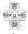
Fig. 2 is a front cross-sectional view of the multi-functional true triaxial shear test device for hard rocks with high temperature and high pressure according to the present invention; -
Fig. 3 is a lateral cross-sectional view of the multi-functional true triaxial shear test device for hard rocks with high temperature and high pressure according to the present invention; -
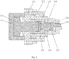
Fig. 4 is a schematic diagram of the structure of a left-end combination tangential loading oil cylinder of the multi-functional true triaxial shear test device for hard rocks with high temperature and high pressure according to the present invention; -
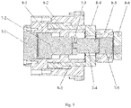
Fig. 5 is a schematic diagram of the structure of a front-end combination lateral loading oil cylinder of the multi-functional true triaxial shear test device for hard rocks with high temperature and high pressure according to the present invention; -
Fig. 6 is a stereogram of the structure of the left-end combination tangential loading oil cylinder of the multi-functional true triaxial shear test device for hard rocks with high temperature and high pressure according to the present invention; -
Fig. 7 is a front hydraulic principle view of the multi-functional true triaxial shear test device for hard rocks, with high temperature and high pressure according to the present invention; and -
Fig. 8 is the lateral hydraulic principle view of the multi-functional true triaxial shear test device for hard rocks with high temperature and high pressure according to the present invention. - The following is a detailed description of a multi-functional true triaxial shear test device for hard rocks with high temperature and high pressure according to the present invention in combination with the drawings and specific embodiments.
- As shown in
Figs 1-8 , a multi-functional true triaxial shear test device for hard rocks with high temperature and high pressure comprises a hydraulic system, a left-end combination tangential loading oil cylinder, a right-end combination tangential loading oil cylinder, a front-end combination lateral loading oil cylinder, a rear-end combination lateral loading oil cylinder, an upper normal loading oil cylinder3, a lower normalloading oil cylinder 6, anannular framework 11, a lateral auxiliary push-and-pull framework 12, an annularframework support platform 13, ahorizontal support platform 14 and a test chamber 16.As shown inFigs. 1 and 2 , theannular framework 11 is fixedly mounted on an upper surface of the annularframework support platform 13 through bolts, thehorizontal support platform 14 is arranged at a rear end of the annularframework support platform 13, and thehorizontal support platform 14 and the annularframework support platform 13 are both fixedly mounted on the ground. The lateral auxiliary push-and-pull framework 12 is arranged on thehorizontal support platform 14 through aguide rail 15 and a sliding block. Through the adoption of an annular structure framework which is integrally forged, the stiffness of the device is greatly improved. As shown inFigs. 1-3 , the left-end combination tangential loading oil cylinder is mounted in a left-end through hole of theannular framework 11, the right-end combination tangential loading oil cylinder is mounted in a right-end through hole of theannular framework 11, the upper normalloading oil cylinder 3 is arranged in an upper-end through hole of theannular framework 11, and the lower normalloading oil cylinder 6 is arranged in a lower-end through hole of theannular framework 11. As shown inFigs. 1 and3 , the front-end combination lateral loading oil cylinder is mounted in a front-end through hole of the lateral auxiliary push-and-pull framework 12, and the rear-end combination lateral loading oil cylinder is arranged in a rear-end through hole of the lateral auxiliary push-and-pull framework 12. As shown inFigs. 1-3 ,a plurality ofdisplacement sensors 19 are respectively arranged at a rear end of the left-end combination tangential loading oil cylinder, a rear end of the right-end combination tangential loading oil cylinder, a rear end of the front-end combination lateral loading oil cylinder, a rear end of the rear-end combination lateral loading oil cylinder and a rear end of the upper normalloading oil cylinder 3, and the displacement sensors 19are connected with a computer (not shown). As shown inFigs. 7 and8 , the left-end combination tangential loading oil cylinder, the right-end combination tangential loading oil cylinder, the front-end combination lateral loading oil cylinder, the rear-end combination lateral loading oil cylinder, the upper normalloading oil cylinder 3 and the lower normalloading oil cylinder 6 are all connected with the hydraulic system. As shown inFigs. 1-3 , thetest chamber 16 is mounted in a rectangular through hole of the lateral auxiliary push-and-pull framework 12, ashear box 17 is placed in thetest chamber 16, androck samples 18 are placed in theshear box 17. - As shown in
Fig. 2 , the left-end combination tangential loading oil cylinder comprises a left tangential upperloading oil cylinder 1 and a left tangential lowerloading oil cylinder 2, and the left tangential lowerloading oil cylinder 2 is coaxially mounted on the left tangential upperloading oil cylinder 1. As shown inFig. 2 , the right-end combination tangential loading oil cylinder comprises a right tangential upperloading oil cylinder 5 and a right tangential lowerloading oil cylinder 4, and the right tangential upperloading oil cylinder 5 is coaxially mounted on the right tangential lower loading oil cylinder 4.As shown inFig. 4 , the left tangential upperloading oil cylinder 1 and the right tangential lowerloading oil cylinder 4 are the same in structure, and both consist of a first sealing cover 1-1, a first piston 1-2, a first connecting plate 1-3, a first force measuring sensor 1-4 and a first force transmitting plate 1-5.Each first piston 1-2 is arranged in an inner cavity of the corresponding first sealing cover 1-1, each first piston 1-2 is connected with one end of the corresponding first connecting plate 1-3, the other end of the first connecting plate 1-3 is connected with one end of the corresponding first force measuring sensor 1-4, and the other end of the first force measuring sensor 1-4 is connected with the corresponding first force transmitting plate 1-5. As shown inFig. 4 , the left tangential lower loading oil cylinder 2 and the right tangential upper loading oil cylinder 5 are the same in structure and both consist of a second sealing cover 2-1, a second counterforce cylinder barrel 2-2, a second piston 2-3, a second sealing flange 2-4, a second force measuring sensor 2-5 and a second force transmitting plate 2-6, wherein each second sealing cover 2-1 is coaxially mounted on an outer peripheral surface of the corresponding first piston 1-2, a boss at one end of each second sealing cover 2-1 extends into the inner cavity of the corresponding first sealing cover 1-1 to be in connection with the corresponding first sealing cover 1-1 in a sealed manner, each second piston 2-3 and the corresponding second counterforce cylinder barrel 2-2 are coaxially mounted at the other end of the corresponding second sealing cover 2-1, each second counterforce cylinder barrel 2-2 is coaxially mounted on an outer peripheral surface of the corresponding second piston 2-3 and is fixedly mounted on the corresponding second sealing cover 2-1 through bolts, an extending end of each second piston 2-3 is connected with one end of the second sealing flange 2-4, the other end of the second sealing flange 2-4 is connected with one end of the corresponding second force measuring sensor 2-5, the other end of the second force measuring sensor 2-5 is connected with the second force transmitting plate 2-6, the first force transmitting plate 1-5 penetrates through the second force transmitting plate 2-6, and the first force transmitting sensors 1-4 and the second force transmitting sensors 2-5 are connected with the computer. - As shown in
Fig. 3 , the front-end combination lateral loading oil cylinder comprises a front lateral upperloading oil cylinder 8 and a front lateral lowerloading oil cylinder 7, and the front lateral lowerloading oil cylinder 7 is coaxially mounted at an inner cavity of the front lateral upperloading oil cylinder 8. As shown inFig. 3 , the rear-end combination lateral loading oil cylinder comprises a rear lateral upperloading oil cylinder 10 and a rear lateral lowerloading oil cylinder 9, and the rear lateral lowerloading oil cylinder 9 is coaxially mounted at an inner cavity of the rear lateral upperloading oil cylinder 10. As shown inFig. 5 , the front lateral upperloading oil cylinder 8 and the rear lateral upperloading oil cylinder 10 are the same in structure and both consist of an upper lateral sealing cover 8-1, an upper lateral counterforce cylinder barrel 8-2, an upper lateral piston 8-3, an upper lateral sealing flange 8-4, an upper lateral force measuring sensor 8-5 and an upper lateral force transmitting plate 8-6. Each upper lateral piston 8-3 is coaxially mounted at a first boss of the corresponding upper lateral sealing cover 8-1, each upper lateral counterforce cylinder barrel 8-2 is coaxially mounted at a second boss of the corresponding upper lateral sealing cover 8-1, an inner surface of each upper lateral counterforce cylinder barrel 8-2 is in contact with an outer surface of the corresponding upper lateral piston 8-3, each upper lateral piston 8-3 is connected with one end of the corresponding upper lateral sealing flange 8-4, the other end of the upper lateral sealing flange 8-4 is connected with one end of the corresponding upper lateral force measuring sensor 8-5, and the other end of the upper lateral force measuring sensor 8-5 is connected with the corresponding upper lateral force transmitting plate 8-6. As shown inFig. 5 , the front lateral lowerloading oil cylinder 7 and the rear lateral lowerloading oil cylinder 9 are the same in structure and both consist of a lower lateral sealing cover 7-1, a lower lateral piston 7-2, a lower lateral connecting plate 7-3, a lower lateral force measuring sensor 7-4 and a lower lateral force transmitting plate 7-5. One end of each lower lateral sealing cover 7-1 extends into an inner cavity of the corresponding upper lateral sealing cover 8-1, a flange end of each lower lateral sealing cover 7-1 is fixedly mounted on the corresponding upper lateral sealing cover 8-1 through bolts, each lower lateral piston 7-2 is mounted at an inner cavity of the corresponding upper lateral sealing cover 8-1, each lower lateral piston 7-2 is located in a sealing cavity formed by the corresponding upper lateral sealing cover 8-1 and the corresponding lower lateral sealing cover 7-1, a part of each lower lateral piston 7-2 extends out of a boss in the corresponding upper lateral sealing cover 8-1, and is connected with one end of the corresponding lower lateral connecting plate 7-3, the other end of the lower lateral connecting plate 7-3 is connected with one end of the corresponding lower lateral force measuring sensor 7-4, the other end of the lower lateral force measuring sensor 7-4 is connected with the corresponding lower lateral force transmitting plate 7-5, the lower lateral force transmitting plate 7-5 penetrates through the upper lateral force transmitting plate 8-6, and the upper lateral force measuring sensors 8-5 and the lower lateral force measuring sensors 7-4 are both connected with the computer. - As shown in
Fig. 2 , the upper normalloading oil cylinder 3 consists of an upper normal sealing cover 3-1, an upper normal cylinder barrel 3-2, an upper normal piston 3-3, an upper normal connecting plate 3-4, an upper normal force measuring sensor 3-5 and an upper normal force transmitting plate 3-6. A flange end of the upper normal sealing cover 3-1 is connected with a flange end of the upper normal cylinder barrel 3-2, the upper normal piston 3-3 is arranged on an inner wall of the upper normal cylinder barrel 3-2, a part of the upper normal piston 3-3 extends out of the upper normal cylinder barrel 3-2 and is connected with one end of the upper normal connecting plate 3-4, the other end of the upper normal connecting plate 3-4 is connected with one end of the upper normal force measuring sensor 3-5, the other end of the upper normal force measuring sensor 3-5 is connected with the upper normal force transmitting plate 3-6, and each upper normal force measuring sensor 3-5 is connected with the computer. - As shown in
Fig. 2 , the lower normalloading oil cylinder 6 consists of a lower normal sealing plate 6-1, a lower normal piston 6-2, a lower normal sealing flange 6-3, a lower normal connecting plate 6-4, a lower normal force measuring sensor 6-5 and a lower normal force transmitting plate 6-6, wherein the lower normal piston 6-2 is arranged in an inner cavity of the lower normal sealing plate 6-1, a flange end of the lower normal sealing plate 6-1 is connected with the lower normal sealing flange 6-3, a part of the lower normal piston 6-2 extends out of the lower normal sealing flange 6-3 and is connected with one end of the lower normal connecting plate, the other end of the lower normal connecting plate 6-4 is connected with one end of the lower normal force measuring sensor 6-5, the other end of the lower normal force measuring sensor 6-5 is connected with the lower normal force transmitting plate 6-6, and each lower normal force measuring sensor 6-5 is connected with the computer. - Two penetrating cooling water through holes are formed in a front end of the first force transmitting plates 1-5 of the left-end combination tangential loading oil cylinder, two penetrating cooling water through holes are formed in a front end of the first force transmitting plates 1-5 of the right-end combination tangential loading oil cylinder, two penetrating cooling water through holes are formed in a front end of the upper lateral force transmitting plate 8-6 of the front-end combination lateral loading oil cylinder , two penetrating cooling water through holes are formed in a front end of the upper lateral force transmitting plate 8-6 of the rear-end combination lateral loading oil cylinder, two penetrating cooling water through holes are formed in a front end of the lower lateral force transmitting plate 7-5 of the front-end combination lateral loading oil cylinder, two penetrating cooling water through holes are formed in a front end of the lower lateral force transmitting plate 7-5 of the rear-end combination lateral loading oil cylinder, two penetrating cooling water through holes are formed in a front end of the upper normal force transmitting plate 3-6 of the upper normal loading oil cylinder 3, and two penetrating cooling water through holes are formed in a front end of the lower normal force transmitting plate 6-6 of the lower normal loading oil cylinder 6.The cooling water through holes are connected with a cooling water device (not shown) through rubber pipes 20 (shown in
Fig. 6 ), and the model of the cooling water device is CF311HC. - As shown in
Figs. 7 and8 , the hydraulic system comprises a first hydraulic station 22, a second hydraulic station 23, a third hydraulic station 24, a first energy accumulator 25, a second energy accumulator 26, a third energy accumulator 27 and a plurality of servo valves 21.As shown inFig. 7 , the first hydraulic station 22 is connected with the first energy accumulator 25 through a high pressure resistant oil pipe, and the first energy accumulator 25 is connected with the left tangential upper loading oil cylinder 1, the left tangential lower loading oil cylinder 2 and the upper normal loading oil cylinder 3 through the high pressure resistant oil pipe and the servo valves 21.As shown inFig. 7 , the second hydraulic station 23 is connected with the second energy accumulator 26 through a high pressure resistant oil pipe, and the second energy accumulator 26 is connected with the right tangential upper loading oil cylinder 5, the right tangential lower loading oil cylinder 4 and the lower normal loading oil cylinder 6 through the high pressure resistant oil pipe and the servo valves 21.As shown inFig. 8 , the third hydraulic station 24 is connected with the third energy accumulator 27 through a high pressure resistant oil pipe, the third energy accumulator 27 is connected with the front lateral upper loading oil cylinder 8 and the front lateral lower loading oil cylinder 7 and the rear lateral upper loading oil cylinder10 and the rear lateral lower loading oil cylinder 9 through the high pressure resistant oil pipe and the servo valves 21. The firsthydraulic station 22, the secondhydraulic station 23 and the thirdhydraulic station 24 are the same in structure and all comprise a hydraulic pump and an oil tank, and an oil inlet of each hydraulic pump is connected with an oil outlet of the corresponding oil tank through the corresponding high pressure resistant oil pipe. Through cooperative effects of the hydraulic pumps and theservo valves 21, high-frequency motion of the actuator is guaranteed, and completion of a constant normal stiffness test is guaranteed. Besides, the hydraulic pumps are connected with a servo driver and cooling water in series, and firstly, when pressure in the oil cylinders is reduced, the servo driver feeds back the pressure in the oil cylinders to the hydraulic pumps in real time, so that the hydraulic pumps work, the pressure in the oil cylinders is complemented, or else, the hydraulic pumps stop working. In addition, when the pressure in the oil cylinders is reduced, the energy accumulators can complement pressure for the oil cylinders continuously. In this manner, continuous temperature rise caused by work of the hydraulic pumps can be reduced, and completion of the long-time constant normal stiffness test can be guaranteed. - As shown in
Figs. 1-3 , thetest chamber 16 is a thermostaticchamber, and therock samples 18 in theshear box 17 are heated in a ceramic radiation heating manner. - A multi-functional true triaxial shear test method for hard rocks with high temperature and high pressure for the device, comprises the following steps:
- Step 1: loading the
rock samples 18 into theshear box 17, and mounting a deformation sensor between therock samples 18 and theshear box 17. - Step 2: putting the
shear box 17 loaded with therock samples 18 at a central position of thetest chamber 16. - Step 3: pushing the lateral auxiliary push-and-
pull framework 12 to be away from theannular framework 11, and placing thetest chamber 16 at a central position of the lateral auxiliary push-and-pull framework 12. - Step 4: pushing the lateral auxiliary push-and-
pull framework 12 into theannular framework 11, enabling therock samples 18 to be located at a geometric center position of theannular framework 11, and enabling a center connecting line of the upper-end through hole and the lower-end through hole of theannular framework 11 to be perpendicular to a water level; and enabling a center connecting line of the left-end through hole and the right-end through hole of theannular framework 11 to be parallel to the water level, and enabling an intersection point of the two center connecting lines to be a geometric center point of theannular framework 11. - Step 5: completing centring and clamping of the
rock samples 18 through performing displacement control on the left tangential upperloading oil cylinder 1, the left tangential lowerloading oil cylinder 2, the right tangential upperloading oil cylinder 5, the right tangential lowerloading oil cylinder 4, the front lateral upperloading oil cylinder 8, the front lateral lowerloading oil cylinder 7, the rear lateral upperloading oil cylinder 10, the rear lateral lowerloading oil cylinder 9, the upper normalloading oil cylinder 3 and the lower normalloading oil cylinder 6. - Step 6: starting the cooling water device, so that the cooling water can circulate in the force transmitting plates of the left tangential upper
loading oil cylinder 1, the left tangential lowerloading oil cylinder 2, the right tangential upperloading oil cylinder 5, the right tangential lowerloading oil cylinder 4, the upper normalloading oil cylinder 3 and the lower normalloading oil cylinder 6. - Step 7: starting the
test chamber 16, and presetting target temperature so that the temperature in thetest chamber 16 can reach the preset target temperature. - Step 8: starting the first
hydraulic station 22, the secondhydraulic station 23 and the thirdhydraulic station 24, performing force control on the left tangential upper loading oil cylinder, the left tangential lower loading oil cylinder, the right tangential upper loading oil cylinder, the right tangential lower loading oil cylinder, the front lateral upper loading oil cylinder, the front lateral lower loading oil cylinder, the rear lateral upper loading oil cylinder, the rear lateral lower loading oil cylinder, the upper normal loading oil cylinder and the lower normal loading oil cylinder at constant loading rate through force control, so that values τ=σp=σn of six boundary surfaces of the rock samples under a hydrostatic pressure state are increased to a target value of normal stress σn1, wherein τ is shear stress, σp is lateral stress, and σn is normal stress. - Step 9: performing servo control on the upper normal
loading oil cylinder 3 and the lower normalloading oil cylinder 6 so as to guarantee the normal stress unchanged; and then performing force control on the left tangential upperloading oil cylinder 1, the left tangential lowerloading oil cylinder 2, the right tangential upperloading oil cylinder 5, the right tangential lowerloading oil cylinder 4, the front lateral upperloading oil cylinder 8, the front lateral lowerloading oil cylinder 7, the rear lateral upperloading oil cylinder 10 and the rear lateral lowerloading oil cylinder 9 at constant loading rate through force control, so that a stress of a shear surface and a stress of a lateral surface are increased to a target value of the lateral stress σp1. - Step 10: performing servo control on the front lateral upper
loading oil cylinder 8, the front lateral lowerloading oil cylinder 7, the rear lateral upperloading oil cylinder 10, the rear lateral lowerloading oil cylinder 9, the upper normalloading oil cylinder 3 and the lower normalloading oil cylinder 6 so as to guarantee the lateral stress and the normal stress not to be unchanged; and then performing force control on the left tangential upperloading oil cylinder 1, the left tangential lowerloading oil cylinder 2, the right tangential upperloading oil cylinder 5 and the right tangential lowerloading oil cylinder 4 at constant loading rate through force control, so that the stress of the shear surface is increased to the stress τ0 of primary rocks. - Step 11: performing servo control on the front lateral upper
loading oil cylinder 8, the front lateral lowerloading oil cylinder 7, the rear lateral upperloading oil cylinder 10, the rear lateral lowerloading oil cylinder 9, the upper normalloading oil cylinder 3 and the lower normalloading oil cylinder 6 so as to guarantee the lateral stress and the normal stress unchanged; and besides, performing servo control on the left tangential lowerloading oil cylinder 2 and the right tangential upperloading oil cylinder 5, so that a force bearing process of therock samples 18 in a shear direction is guaranteed, and a left lower cross section and a right upper cross section maintain the stress τ0 of the primary rocks; and then increasing shear force of the left tangential upperloading oil cylinder 1 and the right tangential lowerloading oil cylinder 4 at constant loading rate through displacement control until the shear force reaches residual strength. - Step 12: enabling an interface of the computer to be connected with the force measuring sensors and the
displacement sensors 19, feeding back real-time signals to the computer through the force measuring sensors and thedisplacement sensors 19, and recording displacement, force value data and a rock sample macroscopic breaking mode through the computer.
Claims (9)
- A multi-functional true triaxial shear test device for hard rocks with high temperature and high pressure, comprising a hydraulic system, a left-end combination tangential loading oil cylinder, a right-end combination tangential loading oil cylinder, a front-end combination lateral loading oil cylinder, a rear-end combination lateral loading oil cylinder, an upper normal loading oil cylinder, a lower normal loading oil cylinder, an annular framework, a lateral auxiliary push-and-pull framework, an annular framework support platform, a horizontal support platform and a test chamber;wherein the annular framework is fixedly mounted on an upper surface of the annular framework support platform through bolts, the horizontal support platform is arranged at a rear end of the annular framework support platform, and the horizontal support platform and the annular framework support platform are both fixedly mounted on a ground;wherein the lateral auxiliary push-and-pull framework is arranged on the horizontal support platform through a guide rail and a sliding block;wherein the left-end combination tangential loading oil cylinder is mounted in a left-end through hole of the annular framework, the right-end combination tangential loading oil cylinder is mounted in a right-end through hole of the annular framework, the upper normal loading oil cylinder is arranged in an upper-end through hole of the annular framework, and the lower normal loading oil cylinder is arranged in a lower-end through hole of the annular framework;wherein the front-end combination lateral loading oil cylinder is mounted in a front-end through hole of the lateral auxiliary push-and-pull framework, and the rear-end combination lateral loading oil cylinder is arranged in a rear-end through hole of the lateral auxiliary push-and-pull framework;wherein a plurality of displacement sensors are respectively arranged at a rear end of the left-end combination tangential loading oil cylinder, a rear end of the right-end combination tangential loading oil cylinder, a rear end of the front-end combination lateral loading oil cylinder, a rear end of the rear-end combination lateral loading oil cylinder and a rear end of the upper normal loading oil cylinder;wherein the left-end combination tangential loading oil cylinder, the right-end combination tangential loading oil cylinder, the front-end combination lateral loading oil cylinder, the rear-end combination lateral loading oil cylinder, the upper normal loading oil cylinder and the lower normal loading oil cylinder are respectively connected with the hydraulic system; andwherein the test chamber is mounted in a rectangular through hole of the lateral auxiliary push-and-pull framework, a shear box is placed in the test chamber, and rock samples are placed in the shear box.
- The device according to claim 1, wherein the left-end combination tangential loading oil cylinder comprises a left tangential upper loading oil cylinder and a left tangential lower loading oil cylinder, and the left tangential lower loading oil cylinder is coaxially mounted on the left tangential upper loading oil cylinder; wherein the right-end combination tangential loading oil cylinder comprises a right tangential upper loading oil cylinder and a right tangential lower loading oil cylinder, and the right tangential upper loading oil cylinder is coaxially mounted on the right tangential lower loading oil cylinder; wherein the left tangential upper loading oil cylinder and the right tangential lower loading oil cylinder are the same in structure, and both consist of a first sealing cover, a first piston, a first connecting plate, a first force measuring sensor and a first force transmitting plate; wherein each first piston is arranged in an inner cavity of the corresponding first sealing cover, each first piston is connected with one end of the corresponding first connecting plate, the other end of the first connecting plate is connected with one end of the corresponding first force measuring sensor, and the other end of the first force measuring sensor is connected with the corresponding first force transmitting plate; wherein the left tangential lower loading oil cylinder and the right tangential upper loading oil cylinder are the same in structure and both consist of a second sealing cover, a second counterforce cylinder barrel, a second piston, a second sealing flange, a second force measuring sensor and a second force transmitting plate; and wherein each second sealing cover is coaxially mounted on an outer peripheral surface of the corresponding first piston, a boss at one end of each second sealing cover extends into the inner cavity of the corresponding first sealing cover to be in connection with the corresponding first sealing cover in a sealed manner, each second piston and the corresponding second counterforce cylinder barrel are coaxially mounted at the other end of the corresponding second sealing cover, each second counterforce cylinder barrel is coaxially mounted on an outer periphery surface of the corresponding second piston and is fixedly mounted on the corresponding second sealing cover through bolts, an extending end of each second piston is connected with one end of the second sealing flange, the other end of the second sealing flange is connected with one end of the corresponding second force measuring sensor, the other end of the second force measuring sensor is connected with the second force transmitting plate, and each first force transmitting plate penetrates through the corresponding second force transmitting plate.
- The device according to claim 1, wherein the front-end combination lateral loading oil cylinder comprises a front lateral upper loading oil cylinder and a front lateral lower loading oil cylinder, and the front lateral lower loading oil cylinder is coaxially mounted at an inner cavity of the front lateral upper loading oil cylinder; wherein the rear-end combination lateral loading oil cylinder comprises a rear lateral upper loading oil cylinder and a rear lateral lower loading oil cylinder, and the rear lateral lower loading oil cylinder is coaxially mounted at an inner cavity of the rear lateral upper loading oil cylinder; wherein the front lateral upper loading oil cylinder and the rear lateral upper loading oil cylinder are the same in structure and both consist of an upper lateral sealing cover, an upper lateral counterforce cylinder barrel, an upper lateral piston, an upper lateral sealing flange, an upper lateral force measuring sensor and an upper lateral force transmitting plate; wherein each upper lateral piston is coaxially mounted at a first boss of the corresponding upper lateral sealing cover, each upper lateral counterforce cylinder barrel is coaxially mounted at a second boss of the corresponding upper lateral sealing cover, an inner surface of each upper lateral counterforce cylinder barrel is in contact with an outer surface of the corresponding upper lateral piston, each upper lateral piston is connected with one end of the corresponding upper lateral sealing flange, the other end of the upper lateral sealing flange is connected with one end of the corresponding upper lateral force measuring sensor, and the other end of the upper lateral force measuring sensor is connected with the corresponding upper lateral force transmitting plate; wherein the front lateral lower loading oil cylinder and the rear lateral lower loading oil cylinder are the same in structure and both consist of a lower lateral sealing cover, a lower lateral piston, a lower lateral connecting plate, a lower lateral force measuring sensor and a lower lateral force transmitting plate; and wherein one end of each lower lateral sealing cover extends into an inner cavity of the corresponding upper lateral sealing cover, a flange end of each lower lateral sealing cover is fixedly mounted on the corresponding upper lateral sealing cover through bolts, each lower lateral piston is mounted at an inner cavity of the corresponding upper lateral sealing cover, each lower lateral piston is located in a sealing cavity formed by the corresponding upper lateral sealing cover and the corresponding lower lateral sealing cover, a part of each lower lateral piston extends out of a boss in the corresponding upper lateral sealing cover, and is connected with one end of the corresponding lower lateral connecting plate, the other end of the lower lateral connecting plate is connected with one end of the corresponding lower lateral force measuring sensor, the other end of the lower lateral force measuring sensor is connected with the corresponding lower lateral force transmitting plate, and each lower lateral force transmitting plate penetrates through the corresponding upper lateral force transmitting plate.
- The device according to claim 1, wherein the upper normal loading oil cylinder consists of an upper normal sealing cover, an upper normal cylinder barrel, an upper normal piston, an upper normal connecting plate, an upper normal force measuring sensor and an upper normal force transmitting plate; and wherein a flange end of the upper normal sealing cover is connected with a flange end of the upper normal cylinder barrel, the upper normal piston is arranged on an inner wall of the upper normal cylinder barrel, a part of the upper normal piston extends out of the upper normal cylinder barrel, and is connected with one end of the upper normal connecting plate, the other end of the upper normal connecting plate is connected with one end of the upper normal force measuring sensor, and the other end of the upper normal force measuring sensor is connected with the upper normal force transmitting plate.
- The device according to claim 1, wherein the lower normal loading oil cylinder consists of a lower normal sealing plate, a lower normal piston, a lower normal sealing flange, a lower normal connecting plate, a lower normal force measuring sensor and a lower normal force transmitting plate; and wherein the lower normal piston is arranged in an inner cavity of the lower normal sealing plate, a flange end of the lower normal sealing plate is connected with the lower normal sealing flange, a part of the lower piston extends out of the lower normal sealing flange, and is connected with one end of the lower normal connecting plate, the other end of the lower normal connecting plate is connected with one end of the lower normal force measuring sensor, and the other end of the lower normal force measuring sensor is connected with the lower normal force transmitting plate.
- The device according to claim 1, wherein two penetrating cooling water through holes are formed in a front end of a first force transmitting plate of the left-end combination tangential loading oil cylinder, two penetrating cooling water through holes are formed in a front end of a first force transmitting plate of the right-end combination tangential loading oil cylinder, two penetrating cooling water through holes are formed in a front end of an upper lateral force transmitting plate of the front-end combination lateral loading oil cylinder, two penetrating cooling water through holes are formed in a front end of an upper lateral force transmitting plate of the rear-end combination lateral loading oil cylinder, two penetrating cooling water through holes are formed in a front end of a lower lateral force transmitting plate of the front-end combination lateral loading oil cylinder, two penetrating cooling water through holes are formed in a front end of a lower lateral force transmitting plate of the rear-end combination lateral loading oil cylinder, two penetrating cooling water through holes are formed in a front end of an upper normal force transmitting plate of the upper normal loading oil cylinder, and two penetrating cooling water through holes are formed in a front end of a lower normal force transmitting plate of the lower normal loading oil cylinder; and wherein the cooling water through holes are connected with a cooling water device through rubber pipes.
- The device according to claim 1, wherein the hydraulic system comprises a first hydraulic station, a second hydraulic station, a third hydraulic station, a first energy accumulator, a second energy accumulator, a third energy accumulator and a plurality of servo valves; wherein the first hydraulic station is connected with the first energy accumulator through a high pressure oil resistant pipe, and the first energy accumulator is connected with a left tangential upper loading oil cylinder, a left tangential lower loading oil cylinder and the upper normal loading oil cylinder through the high pressure resistant oil pipe and the servo valves; wherein the second hydraulic station is connected with the second energy accumulator through a high pressure resistant oil pipe, and the second energy accumulator is connected with a right tangential upper loading oil cylinder, a right tangential lower loading oil cylinder and the lower normal loading oil cylinder through the high pressure resistant oil pipe and the servo valves; wherein the third hydraulic station is connected with the third energy accumulator through a high pressure resistant oil pipe, the third energy accumulator is connected with a front lateral upper loading oil cylinder and a front lateral lower loading oil cylinder and a rear lateral upper loading oil cylinder and a rear lateral lower loading oil cylinder through the high pressure resistant oil pipe and the servo valves; and wherein the first hydraulic station, the second hydraulic station and the third hydraulic station are the same in structure and all comprise a hydraulic pump and an oil tank, and an oil inlet of each hydraulic pump is connected with an oil outlet of the corresponding oil tank through the corresponding high pressure resistant oil pipe.
- The device according to claim 1, wherein the test chamber is a thermostatic chamber, and the rock samples in the shear box are heated in a ceramic radiation heating manner.
- A multi-functional true triaxial shear test method for hard rocks with high temperature and high pressure for the device according to claim 1, comprising the following steps:step 1: loading the rock samples into the shear box, and mounting a deformation sensor between the rock samples and the shear box;step 2: putting the shear box loaded with the rock samples at a central position of the test chamber;step 3: pushing the lateral auxiliary push-and-pull framework to be away from the annular framework, and placing the test chamber at a central position of the lateral auxiliary push-and-pull framework;step 4: pushing the lateral auxiliary push-and-pull framework into the annular framework, and enabling the rock samples to be located at a geometric center position of the annular framework;step 5: completing centering and clamping of the rock samples through performing displacement control on a left tangential upper loading oil cylinder, a left tangential lower loading oil cylinder, a right tangential upper loading oil cylinder, a right tangential lower loading oil cylinder, a front lateral upper loading oil cylinder, a front lateral lower loading oil cylinder, a rear lateral upper loading oil cylinder, a rear lateral lower loading oil cylinder, the upper normal loading oil cylinder and the lower normal loading oil cylinder;step 6: starting a cooling water device, so that the cooling water can circulate in force transmitting plates of the left tangential upper loading oil cylinder, the left tangential lower loading oil cylinder, the right tangential upper loading oil cylinder, the right tangential lower loading oil cylinder, the upper normal loading oil cylinder and the lower normal loading oil cylinder;step 7: starting the test chamber, and presetting target temperature so that the temperature in the test chamber can reach the preset target temperature;step 8: starting a first hydraulic station, a second hydraulic station and a third hydraulic station, performing force control on the left tangential upper loading oil cylinder, the left tangential lower loading oil cylinder, the right tangential upper loading oil cylinder, the right tangential lower loading oil cylinder, the front lateral upper loading oil cylinder, the front lateral lower loading oil cylinder, the rear lateral upper loading oil cylinder, the rear lateral lower loading oil cylinder, the upper normal loading oil cylinder and the lower normal loading oil cylinder at constant loading rate through force control, so that values τ=σp=σn of six boundary surfaces of the rock samples under a hydrostatic pressure state are increased to a target value of normal stress σn1, wherein τ is shear stress, σp is lateral stress, and σn is normal stress;step 9: performing servo control on the upper normal loading oil cylinder and the lower normal loading oil cylinder so as to guarantee the normal stress unchanged; and then performing force control on the left tangential upper loading oil cylinder, the left tangential lower loading oil cylinder, the right tangential upper loading oil cylinder, the right tangential lower loading oil cylinder, the front lateral upper loading oil cylinder, the front lateral lower loading oil cylinder, the rear lateral upper loading oil cylinder and the rear lateral lower loading oil cylinder at constant loading rate through force control, so that a stress of a shear surface and a stress of a lateral surface are increased to a target value of the lateral stress σp1;step 10: performing servo control on the front lateral upper loading oil cylinder, the front lateral lower loading oil cylinder, the rear lateral upper loading oil cylinder, the rear lateral lower loading oil cylinder, the upper normal loading oil cylinder and the lower normal loading oil cylinder so as to guarantee the lateral stress and the normal stress unchanged; and then performing force control on the left tangential upper loading oil cylinder, the left tangential lower loading oil cylinder, the right tangential upper loading oil cylinder and the right tangential lower loading oil cylinder at constant loading rate through force control, so that the stress of the shear surface is increased to a stress τ0 of primary rocks;step 11: performing servo control on the front lateral upper loading oil cylinder, the front lateral lower loading oil cylinder, the rear lateral upper loading oil cylinder, the rear lateral lower loading oil cylinder, the upper normal loading oil cylinder and the lower normal loading oil cylinder so as to guarantee the lateral stress and the normal stress unchanged; and besides, performing servo control on the left tangential lower loading oil cylinder and the right tangential upper loading oil cylinder, so that a force bearing process of the rock samples in a shear direction is guaranteed, and a left lower cross section and a right upper cross section maintain the stress τ0 of the primary rocks; and then increasing shear force of the left tangential upper loading oil cylinder and the right tangential lower loading oil cylinder at constant loading rate through displacement control until the shear force reaches residual strength; andstep 12: recording displacement, force value data and a rock sample macroscopic breaking mode through a computer.
Applications Claiming Priority (2)
| Application Number | Priority Date | Filing Date | Title |
|---|---|---|---|
| CN201910904135.3A CN110658085B (en) | 2019-09-24 | 2019-09-24 | A high temperature and high pressure hard rock true triaxial multi-functional shear test device and method |
| PCT/CN2019/108106 WO2021056322A1 (en) | 2019-09-24 | 2019-09-26 | High-temperature and high-pressure hard rock true triaxial multifunctional shear test device and method |
Publications (3)
| Publication Number | Publication Date |
|---|---|
| EP3822611A1 true EP3822611A1 (en) | 2021-05-19 |
| EP3822611A4 EP3822611A4 (en) | 2021-07-21 |
| EP3822611B1 EP3822611B1 (en) | 2024-06-19 |
Family
ID=69038766
Family Applications (1)
| Application Number | Title | Priority Date | Filing Date |
|---|---|---|---|
| EP19925559.7A Active EP3822611B1 (en) | 2019-09-24 | 2019-09-26 | High-temperature and high-pressure hard rock true triaxial multifunctional shear test device and method |
Country Status (5)
| Country | Link |
|---|---|
| US (1) | US11326995B2 (en) |
| EP (1) | EP3822611B1 (en) |
| JP (1) | JP7098188B2 (en) |
| CN (1) | CN110658085B (en) |
| WO (1) | WO2021056322A1 (en) |
Families Citing this family (24)
| Publication number | Priority date | Publication date | Assignee | Title |
|---|---|---|---|---|
| CN111829894B (en) * | 2020-06-24 | 2022-02-08 | 山东大学 | Rock-soil multi-field measurement test system and method |
| CN112345383B (en) * | 2020-09-30 | 2024-09-13 | 华能澜沧江水电股份有限公司 | Multi-directional rock shear test system capable of acoustic emission testing |
| CN112284932B (en) * | 2020-09-30 | 2024-11-12 | 中国科学院武汉岩土力学研究所 | Multifunctional and multi-directional rock shear-seepage-temperature multi-field coupling test system |
| CN112595606A (en) * | 2020-09-30 | 2021-04-02 | 华能澜沧江水电股份有限公司 | Multi-direction rock shearing test system capable of realizing ultrasonic testing |
| CN112284928B (en) * | 2020-09-30 | 2024-09-13 | 中国科学院武汉岩土力学研究所 | Multidirectional rock shearing-seepage coupling test system with acoustic test |
| CN112378778B (en) * | 2020-11-11 | 2021-08-10 | 常州达姆斯检测技术有限公司 | High-low temperature hydraulic large-load compression test system for composite material |
| CN112432845B (en) * | 2020-12-02 | 2022-11-22 | 青岛理工大学 | A shear test system and method for rock joint surfaces under high temperature and high pressure conditions |
| CN112903462A (en) * | 2021-02-04 | 2021-06-04 | 太原理工大学 | Device and method for testing bearing capacity of single-row group column in horizontal goaf under double-shaft loading |
| CN114486565B (en) * | 2022-02-15 | 2023-03-24 | 中国矿业大学 | Rock structural surface dynamic bidirectional shearing experimental system under constant normal stiffness condition |
| CN114813413A (en) * | 2022-03-31 | 2022-07-29 | 山东科技大学 | Rock fracture shear test system and method capable of continuously changing shear direction |
| CN114720263A (en) * | 2022-04-07 | 2022-07-08 | 东北石油大学 | Visual test device and test method for rock fracture in deep high temperature and high pressure environment |
| CN114942196B (en) * | 2022-05-25 | 2025-02-18 | 东北大学 | A cyclic loading and unloading stress path method for studying true triaxial creep characteristics of rock |
| CN115201016A (en) * | 2022-07-27 | 2022-10-18 | 东北大学 | Rheological test device and test method under true triaxial stress path of simulated hard rock |
| CN116067803B (en) * | 2023-02-16 | 2023-10-13 | 广西大学 | Experimental equipment and methods for true three-dimensional dynamic and static combined shear under high temperature and high permeability chemical coupling |
| CN116242693A (en) * | 2023-02-20 | 2023-06-09 | 福建工程学院 | An underground engineering rock mass shear simulation test device, test method and test machine |
| CN116296867B (en) * | 2023-03-02 | 2025-10-17 | 深圳大学 | Deep rock in-situ environment reconstruction and three-dimensional force thermal acoustic shock flow multi-field test system |
| CN118090427B (en) * | 2024-03-08 | 2024-11-12 | 东北大学 | A true triaxial time-dependent disturbance test device for deep-buried hard rock |
| CN118225561A (en) * | 2024-05-23 | 2024-06-21 | 东北大学 | A true triaxial rock sample holder suitable for high temperature and complex unloading stress paths |
| CN118242329B (en) * | 2024-05-27 | 2024-09-17 | 东北大学 | A hierarchical synchronous loading actuator |
| CN118294633B (en) * | 2024-06-05 | 2024-08-09 | 中国石油大学(华东) | Deep oil and gas reservoir heat flow solidification coupling exploitation experimental device and simulation system |
| CN119272522B (en) * | 2024-10-14 | 2025-05-27 | 广西大学 | Failure criterion of dynamic disturbance of rock mass structural surface under true three-dimensional stress |
| CN119246216B (en) * | 2024-11-23 | 2025-09-02 | 西南交通大学 | A rock multi-field coupling fatigue performance testing machine and its system |
| CN120577132A (en) * | 2025-06-18 | 2025-09-02 | 中国地质大学(北京) | A rock multi-surface direct shear test system and method under true triaxial stress |
| CN121231240A (en) * | 2025-12-03 | 2025-12-30 | 东北大学 | A test system and method for shear creep of rock mass on a water-bank slope under wet-dry cycle |
Family Cites Families (20)
| Publication number | Priority date | Publication date | Assignee | Title |
|---|---|---|---|---|
| JPH10206306A (en) * | 1997-01-23 | 1998-08-07 | Fujita Corp | Apparatus and method for shear test of ground material |
| JP4098218B2 (en) * | 2003-11-11 | 2008-06-11 | 財団法人電力中央研究所 | Rock shear test method and rock shear test equipment |
| FR2933495B1 (en) * | 2008-07-07 | 2013-01-18 | Univ Lille Sciences Tech | TRIAXIAL CELL OF GEOMATERIALS UNDER PRESSURE AND SHEAR |
| CN201852748U (en) | 2010-11-24 | 2011-06-01 | 大连民族学院 | Loading tester for concrete proportion loading tri-axial pressure |
| CN102353592A (en) * | 2011-05-27 | 2012-02-15 | 长江水利委员会长江科学院 | On-site servo controlled actual triaxial testing apparatus for rock mass |
| JP2015090355A (en) | 2013-11-07 | 2015-05-11 | 株式会社Ihi | Shear testing device and shear testing method |
| CN103822831B (en) * | 2014-02-18 | 2016-01-20 | 东北大学 | A kind of rigidity following loading framed structure |
| CN103969107B (en) * | 2014-05-06 | 2016-04-20 | 广西大学 | High pressure servo moves true triaxial test machine |
| CN204613077U (en) * | 2015-03-06 | 2015-09-02 | 西南石油大学 | True triaxial Rock parameter measurement system |
| CN105300807B (en) * | 2015-10-14 | 2018-02-16 | 太原理工大学 | A kind of high temperature true triaxial Rock experiment machine |
| CN105547849B (en) * | 2016-03-01 | 2018-12-04 | 安徽理工大学 | Large scale stratiform pressure-bearing rock true triaxial adds unloading test device and test method |
| CN105675409B (en) * | 2016-03-31 | 2019-02-01 | 中国电建集团华东勘测设计研究院有限公司 | Integrated rock mass structure plane direct shear instrument and direct shear test method |
| CN206420735U (en) | 2016-09-29 | 2017-08-18 | 中国科学院武汉岩土力学研究所 | A kind of rock mass true triaxial suitable for hyperosmosis shears seepage flow test device |
| CN106596281B (en) * | 2016-12-20 | 2018-03-13 | 东北大学 | A kind of high pressure true triaxial hard rock star spectra data burst test device and method |
| CN107014690B (en) * | 2017-03-24 | 2021-05-28 | 东北大学 | A low-frequency disturbance and high-speed impact type high-voltage true triaxial test device and method |
| CN106769542B (en) | 2017-03-28 | 2019-11-29 | 中国科学院武汉岩土力学研究所 | A kind of rock shearing loading system |
| CN108519293B (en) * | 2018-03-19 | 2021-04-06 | 太原理工大学 | A true triaxial rock shear seepage experimental device |
| CN110062488B (en) * | 2019-04-28 | 2021-04-06 | 湖北工业大学 | A microwave heating triaxial test device and heating method |
| CN110243701B (en) * | 2019-07-05 | 2022-02-01 | 山东科技大学 | Torsion shear test device and method for anchored rock mass |
| CN110658084B (en) * | 2019-09-24 | 2020-09-01 | 东北大学 | A high-rigidity multi-axis high-stress loading frame device |
-
2019
- 2019-09-24 CN CN201910904135.3A patent/CN110658085B/en active Active
- 2019-09-26 WO PCT/CN2019/108106 patent/WO2021056322A1/en not_active Ceased
- 2019-09-26 US US16/965,521 patent/US11326995B2/en active Active
- 2019-09-26 EP EP19925559.7A patent/EP3822611B1/en active Active
- 2019-09-26 JP JP2020542326A patent/JP7098188B2/en active Active
Also Published As
| Publication number | Publication date |
|---|---|
| EP3822611B1 (en) | 2024-06-19 |
| JP7098188B2 (en) | 2022-07-11 |
| JP2022503306A (en) | 2022-01-12 |
| US20210247283A1 (en) | 2021-08-12 |
| CN110658085B (en) | 2021-05-11 |
| US11326995B2 (en) | 2022-05-10 |
| EP3822611A4 (en) | 2021-07-21 |
| WO2021056322A1 (en) | 2021-04-01 |
| CN110658085A (en) | 2020-01-07 |
Similar Documents
| Publication | Publication Date | Title |
|---|---|---|
| US11326995B2 (en) | Multi-functional true triaxial shear test device and method for hard rocks with high temperature and high pressure | |
| CN106198227B (en) | Energy storage drop hammer dynamic and static combined loading test device | |
| CN102042935B (en) | Method for detecting hydrostatic pressure of thin-wall steel pipe under end face seal condition | |
| CN112557203A (en) | Hot hydraulic coupling triaxial test method for fractured rock | |
| CN103163026B (en) | A rock-soil compression-shear rheological testing machine and testing method | |
| WO2022134187A1 (en) | Rock true triaxial dynamic compression shear test apparatus and method in deep complex structure conditions | |
| CN105651671B (en) | Two-dimensional rock sample shear-seepage coupling test device | |
| CN203287254U (en) | Rock hot-set coupling experiment system | |
| CN104777047B (en) | A kind of test method for determining fractured rock loosening strength | |
| CN103018106A (en) | Experimental platform capable of simulating confined water load and baseboard breakage relation in controllable manner | |
| CN104833775B (en) | The threedimensional model experimental rig of the prominent mud geological disaster of simulation gushing water | |
| CN101280682B (en) | Complete hydraulic self-drilling type side pressure equipment | |
| CN109580394B (en) | Pendulum bob rock impact shear creep testing machine and testing method | |
| CN109520851A (en) | Section of jurisdiction faulting of slab ends testing method | |
| CN104196448A (en) | Intelligent on-line deep hole drill carriage for coal mine | |
| CN109083119A (en) | Soil pressure cell inbuilt device and method for embedding suitable for soft clay area | |
| CN111365049A (en) | Hydraulic pallet for mine constant resistance anchor rod (cable) | |
| CN112814739B (en) | A kind of sealing repair method of casing cement ring system for abnormal salt cavity in roof | |
| CN103335631B (en) | A kind of rock movement on-Line Monitor Device and monitoring method thereof | |
| CN109612840B (en) | Experimental device and method for obtaining post-peak curve and residual strength of brittle rock | |
| CN107621415A (en) | A true three-axis multi-functional large-scale deep mine roadway model testing machine | |
| CN204008638U (en) | Wellhole blasting analog simulation experimental provision | |
| CN107121339B (en) | Intelligent constant loading device for surrounding pressure of coal rock wall | |
| CN205781676U (en) | Prestressed concrete cylinder pipe road water pressure test plugging device | |
| CN213929011U (en) | Test device for completing loading of load box and piston stroke value |
Legal Events
| Date | Code | Title | Description |
|---|---|---|---|
| STAA | Information on the status of an ep patent application or granted ep patent |
Free format text: STATUS: UNKNOWN |
|
| STAA | Information on the status of an ep patent application or granted ep patent |
Free format text: STATUS: THE INTERNATIONAL PUBLICATION HAS BEEN MADE |
|
| PUAI | Public reference made under article 153(3) epc to a published international application that has entered the european phase |
Free format text: ORIGINAL CODE: 0009012 |
|
| STAA | Information on the status of an ep patent application or granted ep patent |
Free format text: STATUS: REQUEST FOR EXAMINATION WAS MADE |
|
| 17P | Request for examination filed |
Effective date: 20201028 |
|
| AK | Designated contracting states |
Kind code of ref document: A1 Designated state(s): AL AT BE BG CH CY CZ DE DK EE ES FI FR GB GR HR HU IE IS IT LI LT LU LV MC MK MT NL NO PL PT RO RS SE SI SK SM TR |
|
| A4 | Supplementary search report drawn up and despatched |
Effective date: 20210623 |
|
| RIC1 | Information provided on ipc code assigned before grant |
Ipc: G01N 3/24 20060101AFI20210617BHEP Ipc: G01N 3/10 20060101ALI20210617BHEP |
|
| DAV | Request for validation of the european patent (deleted) | ||
| DAX | Request for extension of the european patent (deleted) | ||
| GRAP | Despatch of communication of intention to grant a patent |
Free format text: ORIGINAL CODE: EPIDOSNIGR1 |
|
| STAA | Information on the status of an ep patent application or granted ep patent |
Free format text: STATUS: GRANT OF PATENT IS INTENDED |
|
| INTG | Intention to grant announced |
Effective date: 20240122 |
|
| GRAS | Grant fee paid |
Free format text: ORIGINAL CODE: EPIDOSNIGR3 |
|
| GRAL | Information related to payment of fee for publishing/printing deleted |
Free format text: ORIGINAL CODE: EPIDOSDIGR3 |
|
| GRAS | Grant fee paid |
Free format text: ORIGINAL CODE: EPIDOSNIGR3 |
|
| GRAA | (expected) grant |
Free format text: ORIGINAL CODE: 0009210 |
|
| STAA | Information on the status of an ep patent application or granted ep patent |
Free format text: STATUS: THE PATENT HAS BEEN GRANTED |
|
| AK | Designated contracting states |
Kind code of ref document: B1 Designated state(s): AL AT BE BG CH CY CZ DE DK EE ES FI FR GB GR HR HU IE IS IT LI LT LU LV MC MK MT NL NO PL PT RO RS SE SI SK SM TR |
|
| REG | Reference to a national code |
Ref country code: GB Ref legal event code: FG4D |
|
| REG | Reference to a national code |
Ref country code: CH Ref legal event code: EP |
|
| REG | Reference to a national code |
Ref country code: DE Ref legal event code: R096 Ref document number: 602019054055 Country of ref document: DE |
|
| PG25 | Lapsed in a contracting state [announced via postgrant information from national office to epo] |
Ref country code: BG Free format text: LAPSE BECAUSE OF FAILURE TO SUBMIT A TRANSLATION OF THE DESCRIPTION OR TO PAY THE FEE WITHIN THE PRESCRIBED TIME-LIMIT Effective date: 20240619 |
|
| PG25 | Lapsed in a contracting state [announced via postgrant information from national office to epo] |
Ref country code: HR Free format text: LAPSE BECAUSE OF FAILURE TO SUBMIT A TRANSLATION OF THE DESCRIPTION OR TO PAY THE FEE WITHIN THE PRESCRIBED TIME-LIMIT Effective date: 20240619 Ref country code: FI Free format text: LAPSE BECAUSE OF FAILURE TO SUBMIT A TRANSLATION OF THE DESCRIPTION OR TO PAY THE FEE WITHIN THE PRESCRIBED TIME-LIMIT Effective date: 20240619 |
|
| REG | Reference to a national code |
Ref country code: LT Ref legal event code: MG9D |
|
| PG25 | Lapsed in a contracting state [announced via postgrant information from national office to epo] |
Ref country code: GR Free format text: LAPSE BECAUSE OF FAILURE TO SUBMIT A TRANSLATION OF THE DESCRIPTION OR TO PAY THE FEE WITHIN THE PRESCRIBED TIME-LIMIT Effective date: 20240920 |
|
| REG | Reference to a national code |
Ref country code: NL Ref legal event code: MP Effective date: 20240619 |
|
| PG25 | Lapsed in a contracting state [announced via postgrant information from national office to epo] |
Ref country code: LV Free format text: LAPSE BECAUSE OF FAILURE TO SUBMIT A TRANSLATION OF THE DESCRIPTION OR TO PAY THE FEE WITHIN THE PRESCRIBED TIME-LIMIT Effective date: 20240619 |
|
| PG25 | Lapsed in a contracting state [announced via postgrant information from national office to epo] |
Ref country code: NO Free format text: LAPSE BECAUSE OF FAILURE TO SUBMIT A TRANSLATION OF THE DESCRIPTION OR TO PAY THE FEE WITHIN THE PRESCRIBED TIME-LIMIT Effective date: 20240919 Ref country code: LV Free format text: LAPSE BECAUSE OF FAILURE TO SUBMIT A TRANSLATION OF THE DESCRIPTION OR TO PAY THE FEE WITHIN THE PRESCRIBED TIME-LIMIT Effective date: 20240619 Ref country code: HR Free format text: LAPSE BECAUSE OF FAILURE TO SUBMIT A TRANSLATION OF THE DESCRIPTION OR TO PAY THE FEE WITHIN THE PRESCRIBED TIME-LIMIT Effective date: 20240619 Ref country code: GR Free format text: LAPSE BECAUSE OF FAILURE TO SUBMIT A TRANSLATION OF THE DESCRIPTION OR TO PAY THE FEE WITHIN THE PRESCRIBED TIME-LIMIT Effective date: 20240920 Ref country code: FI Free format text: LAPSE BECAUSE OF FAILURE TO SUBMIT A TRANSLATION OF THE DESCRIPTION OR TO PAY THE FEE WITHIN THE PRESCRIBED TIME-LIMIT Effective date: 20240619 Ref country code: BG Free format text: LAPSE BECAUSE OF FAILURE TO SUBMIT A TRANSLATION OF THE DESCRIPTION OR TO PAY THE FEE WITHIN THE PRESCRIBED TIME-LIMIT Effective date: 20240619 Ref country code: RS Free format text: LAPSE BECAUSE OF FAILURE TO SUBMIT A TRANSLATION OF THE DESCRIPTION OR TO PAY THE FEE WITHIN THE PRESCRIBED TIME-LIMIT Effective date: 20240919 |
|
| PG25 | Lapsed in a contracting state [announced via postgrant information from national office to epo] |
Ref country code: NL Free format text: LAPSE BECAUSE OF FAILURE TO SUBMIT A TRANSLATION OF THE DESCRIPTION OR TO PAY THE FEE WITHIN THE PRESCRIBED TIME-LIMIT Effective date: 20240619 |
|
| REG | Reference to a national code |
Ref country code: AT Ref legal event code: MK05 Ref document number: 1696203 Country of ref document: AT Kind code of ref document: T Effective date: 20240619 |
|
| PG25 | Lapsed in a contracting state [announced via postgrant information from national office to epo] |
Ref country code: NL Free format text: LAPSE BECAUSE OF FAILURE TO SUBMIT A TRANSLATION OF THE DESCRIPTION OR TO PAY THE FEE WITHIN THE PRESCRIBED TIME-LIMIT Effective date: 20240619 |
|
| PG25 | Lapsed in a contracting state [announced via postgrant information from national office to epo] |
Ref country code: PT Free format text: LAPSE BECAUSE OF FAILURE TO SUBMIT A TRANSLATION OF THE DESCRIPTION OR TO PAY THE FEE WITHIN THE PRESCRIBED TIME-LIMIT Effective date: 20241021 |
|
| PG25 | Lapsed in a contracting state [announced via postgrant information from national office to epo] |
Ref country code: PT Free format text: LAPSE BECAUSE OF FAILURE TO SUBMIT A TRANSLATION OF THE DESCRIPTION OR TO PAY THE FEE WITHIN THE PRESCRIBED TIME-LIMIT Effective date: 20241021 |
|
| PG25 | Lapsed in a contracting state [announced via postgrant information from national office to epo] |
Ref country code: PL Free format text: LAPSE BECAUSE OF FAILURE TO SUBMIT A TRANSLATION OF THE DESCRIPTION OR TO PAY THE FEE WITHIN THE PRESCRIBED TIME-LIMIT Effective date: 20240619 |
|
| PG25 | Lapsed in a contracting state [announced via postgrant information from national office to epo] |
Ref country code: EE Free format text: LAPSE BECAUSE OF FAILURE TO SUBMIT A TRANSLATION OF THE DESCRIPTION OR TO PAY THE FEE WITHIN THE PRESCRIBED TIME-LIMIT Effective date: 20240619 |
|
| PG25 | Lapsed in a contracting state [announced via postgrant information from national office to epo] |
Ref country code: AT Free format text: LAPSE BECAUSE OF FAILURE TO SUBMIT A TRANSLATION OF THE DESCRIPTION OR TO PAY THE FEE WITHIN THE PRESCRIBED TIME-LIMIT Effective date: 20240619 Ref country code: IS Free format text: LAPSE BECAUSE OF FAILURE TO SUBMIT A TRANSLATION OF THE DESCRIPTION OR TO PAY THE FEE WITHIN THE PRESCRIBED TIME-LIMIT Effective date: 20241019 |
|
| PG25 | Lapsed in a contracting state [announced via postgrant information from national office to epo] |
Ref country code: CZ Free format text: LAPSE BECAUSE OF FAILURE TO SUBMIT A TRANSLATION OF THE DESCRIPTION OR TO PAY THE FEE WITHIN THE PRESCRIBED TIME-LIMIT Effective date: 20240619 |
|
| PG25 | Lapsed in a contracting state [announced via postgrant information from national office to epo] |
Ref country code: SK Free format text: LAPSE BECAUSE OF FAILURE TO SUBMIT A TRANSLATION OF THE DESCRIPTION OR TO PAY THE FEE WITHIN THE PRESCRIBED TIME-LIMIT Effective date: 20240619 Ref country code: RO Free format text: LAPSE BECAUSE OF FAILURE TO SUBMIT A TRANSLATION OF THE DESCRIPTION OR TO PAY THE FEE WITHIN THE PRESCRIBED TIME-LIMIT Effective date: 20240619 |
|
| PG25 | Lapsed in a contracting state [announced via postgrant information from national office to epo] |
Ref country code: SM Free format text: LAPSE BECAUSE OF FAILURE TO SUBMIT A TRANSLATION OF THE DESCRIPTION OR TO PAY THE FEE WITHIN THE PRESCRIBED TIME-LIMIT Effective date: 20240619 Ref country code: ES Free format text: LAPSE BECAUSE OF FAILURE TO SUBMIT A TRANSLATION OF THE DESCRIPTION OR TO PAY THE FEE WITHIN THE PRESCRIBED TIME-LIMIT Effective date: 20240619 |
|
| PG25 | Lapsed in a contracting state [announced via postgrant information from national office to epo] |
Ref country code: SM Free format text: LAPSE BECAUSE OF FAILURE TO SUBMIT A TRANSLATION OF THE DESCRIPTION OR TO PAY THE FEE WITHIN THE PRESCRIBED TIME-LIMIT Effective date: 20240619 Ref country code: SK Free format text: LAPSE BECAUSE OF FAILURE TO SUBMIT A TRANSLATION OF THE DESCRIPTION OR TO PAY THE FEE WITHIN THE PRESCRIBED TIME-LIMIT Effective date: 20240619 Ref country code: RO Free format text: LAPSE BECAUSE OF FAILURE TO SUBMIT A TRANSLATION OF THE DESCRIPTION OR TO PAY THE FEE WITHIN THE PRESCRIBED TIME-LIMIT Effective date: 20240619 Ref country code: PL Free format text: LAPSE BECAUSE OF FAILURE TO SUBMIT A TRANSLATION OF THE DESCRIPTION OR TO PAY THE FEE WITHIN THE PRESCRIBED TIME-LIMIT Effective date: 20240619 Ref country code: IS Free format text: LAPSE BECAUSE OF FAILURE TO SUBMIT A TRANSLATION OF THE DESCRIPTION OR TO PAY THE FEE WITHIN THE PRESCRIBED TIME-LIMIT Effective date: 20241019 Ref country code: ES Free format text: LAPSE BECAUSE OF FAILURE TO SUBMIT A TRANSLATION OF THE DESCRIPTION OR TO PAY THE FEE WITHIN THE PRESCRIBED TIME-LIMIT Effective date: 20240619 Ref country code: EE Free format text: LAPSE BECAUSE OF FAILURE TO SUBMIT A TRANSLATION OF THE DESCRIPTION OR TO PAY THE FEE WITHIN THE PRESCRIBED TIME-LIMIT Effective date: 20240619 Ref country code: CZ Free format text: LAPSE BECAUSE OF FAILURE TO SUBMIT A TRANSLATION OF THE DESCRIPTION OR TO PAY THE FEE WITHIN THE PRESCRIBED TIME-LIMIT Effective date: 20240619 Ref country code: AT Free format text: LAPSE BECAUSE OF FAILURE TO SUBMIT A TRANSLATION OF THE DESCRIPTION OR TO PAY THE FEE WITHIN THE PRESCRIBED TIME-LIMIT Effective date: 20240619 |
|
| PG25 | Lapsed in a contracting state [announced via postgrant information from national office to epo] |
Ref country code: IT Free format text: LAPSE BECAUSE OF FAILURE TO SUBMIT A TRANSLATION OF THE DESCRIPTION OR TO PAY THE FEE WITHIN THE PRESCRIBED TIME-LIMIT Effective date: 20240619 |
|
| REG | Reference to a national code |
Ref country code: DE Ref legal event code: R097 Ref document number: 602019054055 Country of ref document: DE |
|
| REG | Reference to a national code |
Ref country code: DE Ref legal event code: R119 Ref document number: 602019054055 Country of ref document: DE |
|
| PG25 | Lapsed in a contracting state [announced via postgrant information from national office to epo] |
Ref country code: DK Free format text: LAPSE BECAUSE OF FAILURE TO SUBMIT A TRANSLATION OF THE DESCRIPTION OR TO PAY THE FEE WITHIN THE PRESCRIBED TIME-LIMIT Effective date: 20240619 |
|
| PG25 | Lapsed in a contracting state [announced via postgrant information from national office to epo] |
Ref country code: MC Free format text: LAPSE BECAUSE OF FAILURE TO SUBMIT A TRANSLATION OF THE DESCRIPTION OR TO PAY THE FEE WITHIN THE PRESCRIBED TIME-LIMIT Effective date: 20240619 |
|
| PLBE | No opposition filed within time limit |
Free format text: ORIGINAL CODE: 0009261 |
|
| STAA | Information on the status of an ep patent application or granted ep patent |
Free format text: STATUS: NO OPPOSITION FILED WITHIN TIME LIMIT |
|
| REG | Reference to a national code |
Ref country code: CH Ref legal event code: PL |
|
| PG25 | Lapsed in a contracting state [announced via postgrant information from national office to epo] |
Ref country code: LU Free format text: LAPSE BECAUSE OF NON-PAYMENT OF DUE FEES Effective date: 20240926 |
|
| 26N | No opposition filed |
Effective date: 20250320 |
|
| GBPC | Gb: european patent ceased through non-payment of renewal fee |
Effective date: 20240926 |
|
| PG25 | Lapsed in a contracting state [announced via postgrant information from national office to epo] |
Ref country code: DE Free format text: LAPSE BECAUSE OF NON-PAYMENT OF DUE FEES Effective date: 20250401 |
|
| PG25 | Lapsed in a contracting state [announced via postgrant information from national office to epo] |
Ref country code: GB Free format text: LAPSE BECAUSE OF NON-PAYMENT OF DUE FEES Effective date: 20240926 |
|
| REG | Reference to a national code |
Ref country code: BE Ref legal event code: MM Effective date: 20240930 |
|
| PG25 | Lapsed in a contracting state [announced via postgrant information from national office to epo] |
Ref country code: BE Free format text: LAPSE BECAUSE OF NON-PAYMENT OF DUE FEES Effective date: 20240930 |
|
| PG25 | Lapsed in a contracting state [announced via postgrant information from national office to epo] |
Ref country code: FR Free format text: LAPSE BECAUSE OF NON-PAYMENT OF DUE FEES Effective date: 20240930 |
|
| PG25 | Lapsed in a contracting state [announced via postgrant information from national office to epo] |
Ref country code: CH Free format text: LAPSE BECAUSE OF NON-PAYMENT OF DUE FEES Effective date: 20240930 |
|
| PG25 | Lapsed in a contracting state [announced via postgrant information from national office to epo] |
Ref country code: IE Free format text: LAPSE BECAUSE OF NON-PAYMENT OF DUE FEES Effective date: 20240926 |
|
| PG25 | Lapsed in a contracting state [announced via postgrant information from national office to epo] |
Ref country code: SE Free format text: LAPSE BECAUSE OF FAILURE TO SUBMIT A TRANSLATION OF THE DESCRIPTION OR TO PAY THE FEE WITHIN THE PRESCRIBED TIME-LIMIT Effective date: 20240619 |
|
| PG25 | Lapsed in a contracting state [announced via postgrant information from national office to epo] |
Ref country code: CY Free format text: LAPSE BECAUSE OF FAILURE TO SUBMIT A TRANSLATION OF THE DESCRIPTION OR TO PAY THE FEE WITHIN THE PRESCRIBED TIME-LIMIT; INVALID AB INITIO Effective date: 20190926 |
|
| PG25 | Lapsed in a contracting state [announced via postgrant information from national office to epo] |
Ref country code: HU Free format text: LAPSE BECAUSE OF FAILURE TO SUBMIT A TRANSLATION OF THE DESCRIPTION OR TO PAY THE FEE WITHIN THE PRESCRIBED TIME-LIMIT; INVALID AB INITIO Effective date: 20190926 |