EP3821773A1 - Food processor - Google Patents
Food processor Download PDFInfo
- Publication number
- EP3821773A1 EP3821773A1 EP19940167.0A EP19940167A EP3821773A1 EP 3821773 A1 EP3821773 A1 EP 3821773A1 EP 19940167 A EP19940167 A EP 19940167A EP 3821773 A1 EP3821773 A1 EP 3821773A1
- Authority
- EP
- European Patent Office
- Prior art keywords
- locking member
- container assembly
- cover
- preparation device
- food preparation
- Prior art date
- Legal status (The legal status is an assumption and is not a legal conclusion. Google has not performed a legal analysis and makes no representation as to the accuracy of the status listed.)
- Pending
Links
Images


Classifications
-
- A—HUMAN NECESSITIES
- A47—FURNITURE; DOMESTIC ARTICLES OR APPLIANCES; COFFEE MILLS; SPICE MILLS; SUCTION CLEANERS IN GENERAL
- A47J—KITCHEN EQUIPMENT; COFFEE MILLS; SPICE MILLS; APPARATUS FOR MAKING BEVERAGES
- A47J27/00—Cooking-vessels
- A47J27/04—Cooking-vessels for cooking food in steam; Devices for extracting fruit juice by means of steam ; Vacuum cooking vessels
-
- A—HUMAN NECESSITIES
- A47—FURNITURE; DOMESTIC ARTICLES OR APPLIANCES; COFFEE MILLS; SPICE MILLS; SUCTION CLEANERS IN GENERAL
- A47J—KITCHEN EQUIPMENT; COFFEE MILLS; SPICE MILLS; APPARATUS FOR MAKING BEVERAGES
- A47J19/00—Household machines for straining foodstuffs; Household implements for mashing or straining foodstuffs
- A47J19/02—Citrus fruit squeezers; Other fruit juice extracting devices
-
- A—HUMAN NECESSITIES
- A47—FURNITURE; DOMESTIC ARTICLES OR APPLIANCES; COFFEE MILLS; SPICE MILLS; SUCTION CLEANERS IN GENERAL
- A47J—KITCHEN EQUIPMENT; COFFEE MILLS; SPICE MILLS; APPARATUS FOR MAKING BEVERAGES
- A47J43/00—Implements for preparing or holding food, not provided for in other groups of this subclass
- A47J43/04—Machines for domestic use not covered elsewhere, e.g. for grinding, mixing, stirring, kneading, emulsifying, whipping or beating foodstuffs, e.g. power-driven
- A47J43/046—Machines for domestic use not covered elsewhere, e.g. for grinding, mixing, stirring, kneading, emulsifying, whipping or beating foodstuffs, e.g. power-driven with tools driven from the bottom side
-
- A—HUMAN NECESSITIES
- A47—FURNITURE; DOMESTIC ARTICLES OR APPLIANCES; COFFEE MILLS; SPICE MILLS; SUCTION CLEANERS IN GENERAL
- A47J—KITCHEN EQUIPMENT; COFFEE MILLS; SPICE MILLS; APPARATUS FOR MAKING BEVERAGES
- A47J43/00—Implements for preparing or holding food, not provided for in other groups of this subclass
- A47J43/04—Machines for domestic use not covered elsewhere, e.g. for grinding, mixing, stirring, kneading, emulsifying, whipping or beating foodstuffs, e.g. power-driven
- A47J43/07—Parts or details, e.g. mixing tools, whipping tools
- A47J43/075—Safety devices
- A47J43/0761—Safety devices for machines with tools driven from the lower side
-
- A—HUMAN NECESSITIES
- A47—FURNITURE; DOMESTIC ARTICLES OR APPLIANCES; COFFEE MILLS; SPICE MILLS; SUCTION CLEANERS IN GENERAL
- A47J—KITCHEN EQUIPMENT; COFFEE MILLS; SPICE MILLS; APPARATUS FOR MAKING BEVERAGES
- A47J27/00—Cooking-vessels
- A47J27/04—Cooking-vessels for cooking food in steam; Devices for extracting fruit juice by means of steam ; Vacuum cooking vessels
- A47J2027/043—Cooking-vessels for cooking food in steam; Devices for extracting fruit juice by means of steam ; Vacuum cooking vessels for cooking food in steam
Definitions
- the invention relates to a technical field of household appliance, and more particularly to a food preparation device.
- a food preparation device is a household appliance that integrates functions of preparing soy milk, grinding dry powder, squeezing juice, mincing meat, shaving ice, and so on. Moreover, the food preparation device is the household appliance used to prepare various kinds of food such as juice, soy milk, jam, dry powder, shaved ice, minced meat and so on, and is a product that is multi-functionalized from a juicing machine.
- the food preparation device commercially available generally adopt a split structure, including a body and a detachable container.
- a motor in the body rotates at a high speed and drives a knife or a stirring member in the container to rotate so as to complete food preparation.
- the container needs to be locked on the body to avoid a safety accident caused by removal of the container during operation of the food preparation device.
- a locking member is provided in the body, and the locking member slides in a horizontal direction toward an inside of the body to cooperate with the container, so as to lock the container and the body together.
- the present invention adopts following technical solutions.
- a food preparation device which includes a body and a container assembly.
- the food preparation device further includes a drive assembly and a first locking member capable of rotating along a circumferential direction of the body; the drive assembly is configured to drive the first locking member to move to a locked position or an unlocked position.
- the first locking member When the first locking member is in the locked position, the first locking member locks the container assembly on the body. When the first locking member is in the unlocked position, the container assembly can be separated from the body.
- the container assembly is mounted vertically onto the body; the container assembly is provided with a convex limiting portion on its side wall, and the first locking member is provided with an abutting portion; and the drive assembly is capable of driving the abutting portion to extend into or out of an upper part of the limiting portion during the rotation of the first locking member.
- the body is provided with a mounting groove for accommodating a bottom of the container assembly, and an inner side of the mounting groove is provided with a groove capable of accommodating the limiting portion; and the abutting portion is capable of extending into or out of the groove along the circumferential direction of the body.
- the drive assembly includes a connecting member, and the connecting member is connected with the first locking member with one end; and a driving member arranged in the body, and the driving member is configured to drive the connecting member to move.
- the food preparation device further includes: a detection mechanism configured to detect whether the first locking member is moved to a designated position to control starting or stopping of the drive assembly.
- the detection mechanism includes: a first sensing member configured to be capable of being triggered by the first locking member in the locked position; and a third sensing member configured to be capable of being triggered by the first locking member in the unlocked position.
- the food preparation device further includes: a detection mechanism configured to detect a mounting state of the container assembly and the body, and control working of the drive assembly according to a detection result.
- the detection mechanism includes a second sensing member.
- the container assembly is provided with a triggering member. When the container assembly is placed on the body, the triggering member triggers the second sensing member to make the drive assembly drive the first locking member to move to the locked position.
- the container assembly includes a main body and a cover being rotatably matched with the main body.
- the triggering member is capable of triggering the second sensing member.
- the triggering member is slidably connected to the body and has a reset function.
- the cover is rotatably matched with the main body, a first inclined surface is provided on the cover, and a second inclined surface is provided on the triggering member.
- the cover rotates in a screwing-tightening direction relative to the main body, the first inclined surface slides along the second inclined surface and pushes the triggering member to slide, so that the triggering member is capable of triggering the second sensing member.
- the cover is configured to be locked with the main body.
- the container assembly is movably connected with a second locking member, and when the first locking member moves to the locked position, the first locking member drives the second locking member to move to lock the cover.
- the second locking member is slidably connected to the main body and has a reset function, and when the second locking member is reset, the cover is unlocked from the main body.
- the cover is rotatably matched with the main body, a block is provided at a bottom of the cover, and the first locking member drives the second locking member to extend into the bottom of the cover and abut the block to prevent the cover from rotating in a screwing-loosening direction relative to the main body.
- a third inclined surface is provided on the first locking member, and when the first locking member moves to the locked position, the second locking member slides along the third inclined surface.
- the present invention provides a food preparation device.
- a user can control the drive assembly by inputting an instruction in a instruction input area.
- the drive assembly can drive the first locking member in the body to move to cause the first locking member to be matched with the limiting portion, by which locking and unlocking of the container assembly and the body will be realized with simple operation and safety performance of the food preparation device is good.
- the first locking member can lock the container assembly and the body together through rotating along the circumferential direction of the body, and thus a moving space required by the locking member is small, which is beneficial to reducing a size of the body.
- orientations or position relationships such as “center”, “upper”, “lower”, “left”, “right”, “vertical”, “horizontal”, “inner”, “outer”, and so on are based on the orientations or position relationships shown in the accompanying drawings, which are used only to facilitate the description of the present disclosure and simplify the description, rather than indicating or implying that the device or element(s) referred to needs to have a specific orientation, be constructed and operated in a specific orientation, and thus the terms are not understood as limiting the present disclosure.
- first”, “second” are merely illustrative, and are not intended to indicate or imply the importance of the corresponding elements or the number of the technical features.
- the terms “first position” and “second position” are two different positions.
- connection may be a fixed connection or a detachable connection.
- the connection may also be a mechanical connection or an electrical connection.
- connection may be a direct connection or an indirect connection via an intermedium, an internal connection between the two components or an interaction between the two components.
- a first feature is "on” or “under” a second feature may include the first feature directly contacts the second feature, or may include the first feature does not directly contact the second feature but through other features therebetween.
- the first feature is "over” or “above” the second feature includes the first feature is directly above and obliquely above the second feature, or simply means that a level height of the first feature is higher than that of the second feature.
- That the first feature is "below” the second feature includes the first feature directly below and obliquely below the second feature, or simply means that the level height of the first feature is less than that of the second feature.
- This embodiment provides a food preparation device, which can be used to prepare many kinds of food such as fruit juice, soy milk, jam, dry powder, shaved ice, minced meat and so on.
- the food preparation device includes a body 1, a container assembly 2 and a steamer assembly 3.
- the body 1 serves as a carrier of the container assembly 2 and the steamer assembly 3, and contains functional components such as a power system, a connection system, and a control system.
- the container assembly 2 can be mounted on the body 1, and a knife assembly and a heating assembly are provided in the container assembly 2.
- the knife assembly is used for further processing of food materials, and the heating assembly is used for heating the container assembly 2.
- the steamer assembly 3 is optional.
- the steamer assembly 3 can be detachably connected to the container assembly 2. When the steamer assembly 3 is used, water contained in the container assembly 2 is heated by the heating component in the container assembly 2, and steam generated will enter the steamer assembly 3.
- the control system includes an instruction input area provided on the body 1 for the user to input a control instruction.
- the instruction input area can be a touch screen, a knob or a button.
- the control system will control the drive assembly 5 to operate according to the instruction to move the first locking member 4 to the locked position or the unlocked position, after receiving the instruction.
- the container assembly 2 includes a cover 21 and a main body, and the main body includes a container 22, a handle 23 and a base 24.
- the cover 21 can be buckled on a top of the container 22, and the handle 23 is arranged on a side of the container 22, so that the user can move the container assembly 2 conveniently by holding the handle 23.
- the cover 21 is also provided with a measuring cup 25, and the measuring cup 25 can be detachably connected with the cover 21.
- the measuring cup 25 can be used as a handle of cover 21 to facilitate the user to open or cover the cover 21.
- the measuring cup 25, after being removed from the cover 21, can be used to measure an appropriate amount of food material by a user conveniently.
- the container 22 is arranged on the base 24, and the base 24 is provided with a structure that cooperates with the body 1 so that the functional components in the body 1 can process the food in the container 22.
- the body 1 includes an upper casing 11 and a lower casing 12. After the upper casing 11 and the lower casing 12 are fixed together, a mounting cavity for accommodating the power system and the control system is formed therebetween.
- a tray 14 is provided on the upper casing 11, and the tray 14 is provided with a mounting groove for carrying the container assembly 2. When the container assembly 2 is arranged on the body 1, a lower end of the container assembly 2 can be inserted into the tray 14, which is beneficial to improving the stability of the container assembly 2.
- the container assembly 2 is provided with a limiting portion 241.
- the body 1 is movably connected with a first locking member 4 (see FIG. 11 ), and a drive assembly 5 is arranged in the body 1.
- the drive assembly 5 can drive the first locking member 4 to switch between a locked position and an unlocked position.
- the drive assembly 5 can drive the first locking member 4 to move to the locked position where the first locking member 4 can cooperate with the limiting portion 241 to prevent the container assembly 2 from being separated from the body 1, so that the purpose of locking the container assembly 2 and the body 1 is achieved.
- the drive assembly 5 drives the first locking member 4 to move to the unlocked position, the limiting portion 241 is disengaged from the first locking member 4, and the container assembly 2 is unlocked from the body 1, so that the container assembly 2 can be removed.
- the limiting portion 241 is provided on a side wall of the base 24 and protruded therefrom, and the first locking member 4 is movably connected with the tray 14.
- the base 24 extends into the tray 14 so as to cooperate with the first locking member 4.
- the container assembly 2 can be mounted vertically onto the tray 14, and the first locking member 4 can move to the upper side of the limiting portion 241 to prevent the container assembly 2 from being pulled out of the tray 14, thereby realizing locking of the container assembly 2 and the body 1.
- the locking realized by moving the first locking member 4 to the upper side of the limiting portion 241 makes the structure simple and the locking effect reliable.
- the first locking member 4 can abut on the upper side of the limiting portion 241 to further limit the container assembly 2.
- the container assembly 2 can also be assembled into the tray 14 in other directions.
- an opening is provided on a side of the tray 14, and the container assembly 2 is horizontally assembled into the tray 14 through the opening, as long as the first locking member 4 can be moved to a moving trajectory of the container assembly 2 when it is removed.
- the locking can also be achieved by other ways such as engaging the limiting portion 241 with the first locking member 4.
- an outer side wall of the container assembly 2 abuts an inner side wall of the mounting groove, that is, the shape and size of an inner space of the mounting groove can be the same as those of the base of the container assembly 2, which is beneficial to improving the limiting effect of the container assembly 2.
- a groove 141 capable of accommodating the limiting portion 241 is provided in an inner side the mounting groove.
- the drive assembly 5 drives the first locking member 4 to the locked position, so that the first locking member 4 extends into the groove 141 and abuts against a top surface of the limiting portion 241 to achieve locking.
- the container assembly 2 is further provided with a protrusion 242 which is located above the limiting portion 241.
- the container assembly 2 drives the first locking member 4 to move, so that the abutting portion 41 slides into the groove 141 and is located between the protrusion 242 and the abutting portion 241, thereby further improving the locking effect of the container assembly 2 and body 1.
- the opening at the top of the groove 141 can be shaded, so that food residues or other sundries can be prevented from falling into the groove 141, and the appearance of the tray 14 become more beautiful.
- the first locking member 4 can rotate along the circumferential direction of the tray 14 and extend into or out of the groove 141.
- the first locking member 4 rotates along the circumferential direction of the tray 14, which can reduce the space required for the movement of the first locking member 4 and be beneficial to making the structure of the food preparation device more compact, and thus a miniaturized design can be realized.
- the tray 14 includes a bottom plate 142 and a side plate connected to the bottom plate 142, and the side plate and the bottom plate 142 are enclosed to form a mounting groove used for accommodating the base of the container assembly 2.
- the side plate may be a double-layer structure formed by a process such as flanging, and the cross-sectional shape of the side plate may be in a U-shape, so that the locking member 4 can be arranged in the double-layer structure of the side plate.
- the side plate includes an inner plate 143 and an outer plate 144 formed by bending the inner plate 143 outward. A cavity is formed between the inner plate 143 and the outer plate 144, and a groove 141 is arranged on the inner plate 143 and communicates with the cavity.
- the first locking member 4 can be slidably arranged in the cavity. According to the structure configuration of the side plate, the first locking member 4 can be hided and the tray 14 can be more beautiful as an appearance member.
- the first locking member 4 slides along the circumferential direction of the cavity, which requires small space and has a limiting effect on the first locking member 4, and thus a space required for the first locking member 4 to lock the container assembly 2 and the body 1 can be beneficially reduced.
- the tray 14 is integrally formed, which is convenient for processing and is simple in structure.
- the first locking member 4 may have an annular structure, so that the stability of the first locking member 4 in the annular cavity is better.
- the abutting portion 41 is provided on the inner side of the first locking member 4.
- the drive assembly 5 drives the first locking member 4 to move to the locked position
- the abutting portion 41 on the first locking member 4 slides into the groove 141, and the limiting portion 241 is located below the abutting portion 41, which will realize the locking of the container assembly 2 and the body 1.
- a stepped surface 1411 is provided in the groove 141.
- the abutting portion 41 overlaps on the stepped surface 1411 to improve the positioning effect of the abutting portion 41 and the groove 141 to the container assembly 2.
- a plurality of limiting portions 241 may be provided on the container assembly 2. After the container assembly 2 is assembled in the body 1, movement of the first locking member 4 makes the first locking member 4 abut on the upper side of each limiting portion 241 and the number of force points between the limiting portion 241 and the first locking member 4 increased, thereby improving the locking effect of the container assembly 2.
- the number of the abutting portions 41 is the same as that of the limiting portions 241 on the container assembly 2, so that the locking effect of the container assembly 2 is improved.
- the protrusion 242 is provided above one of the abutting portions 41, which can form a foolproof structure, so that the container assembly 2 is mounted on the body 1 at a specified angle, thereby improving safety performance.
- the container assembly 2 is provided with two limiting portions 241 which are respectively provided on both sides of the base.
- Two abutting portions 41 are provided on the first locking member 4, and each abutting portion 41 is correspondingly matched with a limiting portion 241 on the container assembly 2.
- a plurality of supporting blocks 15 are also provided on the upper casing 11.
- the supporting blocks 15 each supports the first locking member 4, so that the first locking member 4 is kept to slide horizontally.
- the supporting surface of the supporting block 15 may be a smooth arc surface to reduce the contact area between the supporting surface and the first locking member 4, thereby reducing friction.
- the food preparation device further includes a detection mechanism which can detect whether the container assembly 2 and the body 1 are assembled in place, so as to control the operation of the drive assembly 5 according to the assembled status of the container assembly 2 and the body 1. Specifically, when the detection mechanism detects that the container assembly 2 and the body 1 are assembled in place, and when the user inputs an instruction to lock the body 1 and the container assembly 2 together through the instruction input area on the control system, the drive assembly 5 drives the first locking member 4 to move to the locked position.
- the detection mechanism detects that the container assembly 2 and the body 1 have not been assembled in place, and when the user inputs an instruction to lock the body 1 and the container assembly 2 together through the instruction input area on the control system, the drive assembly 5 will not be started to operate, and the food preparation device can remind the user to check the assembly status of the container assembly 2 and the body 1 in time by means of alarm voice or text display, etc,.
- the container assembly 2 is provided with a triggering member 26.
- the detection mechanism includes a second sensing member 72.
- the triggering member 26 can trigger the second sensing member 72.
- the drive assembly 5 drives the first locking member 4 to move to the locked position to complete the locking of the container assembly 2.
- the locking of the container assembly 2 can also be automatically triggered by the detection mechanism.
- the detection mechanism when the detection mechanism detects that the container assembly 2 is mounted on the body 1 and the cover 21 is assembled in place, the detection mechanism sends a detection signal to the control system.
- the control system will control the action of the drive assembly 5 according to the detection signal to move the first locking member 4 to the locked position without a user's operation, and thus the operation is more convenient and reliable, and the safety performance is good.
- the detection mechanism may also include a resettable adapter 71.
- the adapter 71 can be slidably arranged in the cavity of the tray 14. One end of the adapter 71 penetrates through the tray 14 and can abut against the triggering member 26, and the other end can cooperate with the second sensing member 72 under the drive of the triggering member 26.
- the adapter 71 can automatically reset and be disengaged from the second sensing member 72, and thus the second sensing member 72 is not triggered, so that the drive assembly 5 will not drive the first locking member 4 to move to the locked position.
- the second sensing member 72 and the adapter 71 can be arranged in the cavity of the tray 14. By reasonably using the space between the inner plate 143 and the outer plate 144 in the tray 14, the structure of the food preparation device will be more compact.
- the detection mechanism also includes a second bracket 74, and both the adapter 71 and the second sensing member 72 can be arranged on the second bracket 74.
- a first reset member 73 is provided between the adapter 71 and the second bracket 74. Two ends of the first reset member 73 abut on the second bracket 74 and the adapter 71 respectively to drive the adapter 71 to extend out of the tray 14 so as to cooperate with the triggering member 26.
- the first reset member 73 may be a spring.
- a contact end is also provided on the adaptor 71. During the adapter 71 is sliding upward and downward, and the adaptor 71 can drive the contact end to abut against the second sensing member 72 or disengage from the second sensing member 72.
- the drive assembly 5 includes a mounting frame 51, a driving member and a connecting member 52.
- the driving member is arranged in the mounting frame 51.
- One end of the connecting member 52 is connected to the first locking member 4, and the other end is connected to the driving member.
- the driving member causes the first locking member 4 to move by driving the connecting member 52 to move.
- the driving member may be a motor, and the motor is connected to the connecting member 52 through a transmission mechanism.
- the transmission mechanism converts the rotation movement of the motor into the sliding movement of the connecting member 52, thereby driving the first locking member 4 to slide relative to the body 1.
- the transmission mechanism may include a driving gear connected with the motor and a driven gear meshing with the driving gear.
- the connecting member 52 may be a screw and be penetrated through the driven gear.
- the screw is threadedly connected with the driven gear.
- the rotor drives the driving gear to rotate.
- the driven gear is driven to rotate by the meshing of the driving gear and the driven gear, thereby the screw is driven to move linearly.
- the transmission mechanism may be also other types, such as a gear-rack mechanism.
- the user can input an unlocking instruction at the instruction input area, and the drive assembly 5 will drive the first locking member 4 to move to the unlocked position as shown in FIG. 11 .
- the abutting portion 41 is located outside the groove 141.
- the container assembly 2 can be removed from the body 1 conveniently.
- the drive assembly 5 drives the first locking member 4 to move to the locked position shown in FIG. 12 .
- the abutting portion 41 slides into the groove 141 to cooperate with the limiting portion 241, and thus the container assembly 2 is locked on the body 1.
- the detection mechanism can also detect the position of the first locking member 4 so as to control the start and stop of the drive assembly 5, so that the first locking member 4 moves to the unlocked position or the locked position accurately.
- the detection mechanism further includes a first sensing member 75, a first bracket 76 and a third sensing member 77.
- the first sensing member 75 is mounted on the first bracket 76
- the third sensing member 77 is mounted on the mounting frame 51.
- the drive assembly 5 drives the first locking member 4 to move.
- the first locking member 4 moves to the locked position, as shown in FIG. 12
- the first locking member 4 can trigger the first sensing member 75, and then the drive assembly 5 is controlled to stop, so as to stabilize the first locking member 4 at the locked position.
- the drive assembly 5 drives the first locking member 4 to move to the unlocked position, so that the first locking member 4 can trigger the third sensing member 77, and then the drive assembly 5 is controlled to stop, so as to stabilize the first locking member 4 at the unlocked position.
- the first sensing member 75, the second sensing member 72, and the third sensing member 77 may all be micro switches, which are triggered by pressing a spring sheet of the micro switch.
- first sensing member 75, the second sensing member 72, and the third sensing member 77 may also be other types such as contact sensors or proximity sensors to implement the above functions.
- control system of the food preparation device may be electrically connected to the detection mechanism.
- the micro switch obtains the position information of the first locking member 4 and the mounting state of the container assembly 2 on the body 1, and transmits this information to the control system.
- the control system controls the drive assembly 5 to start or stop according to the received information.
- This embodiment provides a food preparation device.
- the difference of the food preparation device in embodiment 2 from that in embodiment 1 is that the detection mechanism can detect whether the cover 21 and the container 22 are closed in place or not, so as to avoid the cover 21 or the food materials in the container 22 from being thrown out due to the screwing-loosening of the cover 21 when the food preparation device is operating, and thus the safety performance of the food preparation device is improved.
- the triggering member 26 can trigger the second sensing member 72 in the body 1; otherwise, the triggering member 26 cannot trigger the second sensing member 72.
- the sensor 72 determines whether the cover 21 and the container 22 are closed in place.
- the triggering member 26 When the cover 21 and the container 22 are closed in place, the triggering member 26 extends beyond the handle 23 to a longer length, and the triggering member 26 can trigger the second sensing member 72 on the body 1 to generate the information that the cover 21 has been mounted on the container 22 in place. As shown in FIG. 13 , when the cover 21 and the container 22 are not closed in place, the triggering member 26 extends beyond the handle 23 to a short length, and the triggering member 26 cannot trigger the second sensing member 72 on the body 1, such that the cover 21 is determined to be abnormally covered on the container 22.
- the triggering member 26 is provided inside the handle 23, and the handle 23 is provided with a notch 231.
- the cover 21 is provided with a first inclined surface 211, and the triggering member 26 is resetably arranged on the container 22.
- the triggering member 26 is provided with a second inclined surface 261.
- the cover 21 covers the container 22 in a rotating manner.
- the first inclined surface 211 on the cover 21 can be slidably matched with the second inclined surface 261 on the triggering member 26 through the notch 231, so as to drive the triggering member 26 to move.
- the triggering member 26 is retracted into the handle 23 under the action of the second reset member 27.
- the first inclined surface 211 on the cover 21 can be slidably matched with the second inclined surface 261 on the triggering member 26 and push the triggering member 26 to slide downwards, so that the lower end of the triggering member 26 gradually extends out of the handle 23 so as to abut against the adapter 71.
- a food preparation device is provided.
- the difference of the food preparation device in embodiment 3 from those in the above embodiments is that when the container assembly 2 is locked with the body 1 together, the cover 21 can be locked with the main body together, which improves the safety performance of the food preparation device.
- the container assembly 2 is provided with a second locking member 61 which is movable.
- the first locking member 4 can drive the second locking member 61 to move, so as to lock the cover 21 on the main body.
- the second locking member 61 can also be arranged in the handle 23.
- the second locking member 61 is slidably connected with the container 22 in the vertical direction and has a reset function.
- the first locking member 4 is moved to the unlocked position, the second locking member 61 will automatically be reset and the locking of the cover 21 and the container 22 is released, so that the container assembly 2 can be opened.
- the second locking member 61 and the container 22 are connected by a third reset member 62.
- the third reset member 62 may be a spring.
- the first locking member 4 can drive the second locking member 61 to move upwards so as to lock the cover 21.
- the first locking member 4 is provided with a third inclined surface 42 which can slidably cooperate the lower end of the second locking member 61.
- the third inclined surface 42 gradually slides into the groove 141 and cooperates with the lower end of the second locking member 61 extending into the groove 141.
- the third inclined surface 42 gradually decreases in height along the direction of sliding into the groove 141, so that the second locking member 61 slides upwards when sliding along the third inclined surface 42, so that the second locking member 61 achieves the locking of the cover 21.
- a block 212 is provided at the bottom of the cover 21.
- the top end of the second locking member 61 abuts against a side of the block 212 facing away from the screwing-tightening direction of the cover 21, so that the cover 21 is prevented from rotating in the screwing-loosening direction relative to the container 22, and the purpose of locking the cover 21 is achieved.
- the second locking member 61 slides down and no longer abuts against the block 212, and the locking of cover 21 and the container 22 is released.
Abstract
Description
- The invention relates to a technical field of household appliance, and more particularly to a food preparation device.
- A food preparation device is a household appliance that integrates functions of preparing soy milk, grinding dry powder, squeezing juice, mincing meat, shaving ice, and so on. Moreover, the food preparation device is the household appliance used to prepare various kinds of food such as juice, soy milk, jam, dry powder, shaved ice, minced meat and so on, and is a product that is multi-functionalized from a juicing machine.
- Safety performance is vital to the household appliances such as the food preparation device. At present, the food preparation device commercially available generally adopt a split structure, including a body and a detachable container. When the food preparation device is in operation, a motor in the body rotates at a high speed and drives a knife or a stirring member in the container to rotate so as to complete food preparation. At this time, the container needs to be locked on the body to avoid a safety accident caused by removal of the container during operation of the food preparation device. In the prior art, a locking member is provided in the body, and the locking member slides in a horizontal direction toward an inside of the body to cooperate with the container, so as to lock the container and the body together. Although this structure can improve the safety performance of the food preparation device, the locking member occupies a larger space, which makes a size of the body larger.
- Therefore, there is a need for a food preparation device that can lock the container and the body together and can reduce the size of the body.
- It is an objective of the present invention to provide a food preparation device in which a container and a body can be locked together, and a size of the body is small.
- To achieve this objective, the present invention adopts following technical solutions.
- A food preparation device is provided, which includes a body and a container assembly. The food preparation device further includes a drive assembly and a first locking member capable of rotating along a circumferential direction of the body; the drive assembly is configured to drive the first locking member to move to a locked position or an unlocked position.
- When the first locking member is in the locked position, the first locking member locks the container assembly on the body. When the first locking member is in the unlocked position, the container assembly can be separated from the body.
- The container assembly is mounted vertically onto the body; the container assembly is provided with a convex limiting portion on its side wall, and the first locking member is provided with an abutting portion; and the drive assembly is capable of driving the abutting portion to extend into or out of an upper part of the limiting portion during the rotation of the first locking member.
- The body is provided with a mounting groove for accommodating a bottom of the container assembly, and an inner side of the mounting groove is provided with a groove capable of accommodating the limiting portion; and the abutting portion is capable of extending into or out of the groove along the circumferential direction of the body.
- The drive assembly includes a connecting member, and the connecting member is connected with the first locking member with one end; and a driving member arranged in the body, and the driving member is configured to drive the connecting member to move.
- The food preparation device further includes: a detection mechanism configured to detect whether the first locking member is moved to a designated position to control starting or stopping of the drive assembly.
- The detection mechanism includes: a first sensing member configured to be capable of being triggered by the first locking member in the locked position; and a third sensing member configured to be capable of being triggered by the first locking member in the unlocked position.
- The food preparation device further includes: a detection mechanism configured to detect a mounting state of the container assembly and the body, and control working of the drive assembly according to a detection result.
- The detection mechanism includes a second sensing member. The container assembly is provided with a triggering member. When the container assembly is placed on the body, the triggering member triggers the second sensing member to make the drive assembly drive the first locking member to move to the locked position.
- The container assembly includes a main body and a cover being rotatably matched with the main body. When the cover and the main body rotate to a closed position, the triggering member is capable of triggering the second sensing member.
- The triggering member is slidably connected to the body and has a reset function.
- The cover is rotatably matched with the main body, a first inclined surface is provided on the cover, and a second inclined surface is provided on the triggering member.
- When the cover rotates in a screwing-tightening direction relative to the main body, the first inclined surface slides along the second inclined surface and pushes the triggering member to slide, so that the triggering member is capable of triggering the second sensing member.
- When the cover rotates in a screwing-loosening direction relative to the main body, the first inclined surface and the second inclined surface are gradually separated from each other, and the triggering member is reset.
- When the container assembly is locked with the body, the cover is configured to be locked with the main body.
- The container assembly is movably connected with a second locking member, and when the first locking member moves to the locked position, the first locking member drives the second locking member to move to lock the cover.
- The second locking member is slidably connected to the main body and has a reset function, and when the second locking member is reset, the cover is unlocked from the main body.
- The cover is rotatably matched with the main body, a block is provided at a bottom of the cover, and the first locking member drives the second locking member to extend into the bottom of the cover and abut the block to prevent the cover from rotating in a screwing-loosening direction relative to the main body.
- A third inclined surface is provided on the first locking member, and when the first locking member moves to the locked position, the second locking member slides along the third inclined surface.
- The present invention provides a food preparation device. With regard to the food preparation device, after the container assembly is mounted on the body, a user can control the drive assembly by inputting an instruction in a instruction input area. The drive assembly can drive the first locking member in the body to move to cause the first locking member to be matched with the limiting portion, by which locking and unlocking of the container assembly and the body will be realized with simple operation and safety performance of the food preparation device is good. The first locking member can lock the container assembly and the body together through rotating along the circumferential direction of the body, and thus a moving space required by the locking member is small, which is beneficial to reducing a size of the body.
-
-
FIG. 1 is a schematic structural diagram of a food preparation device provided in Embodiment 1 of the present invention. -
FIG. 2 is a schematic structural diagram of the food preparation device provided in Embodiment 1 of the present invention, with a steamer assembly unassembled. -
FIG. 3 is a front view of the food preparation device shown in Embodiment 1 of the present invention, with a steamer assembly unassembled. -
FIG. 4 is a rear view of a container assembly provided in Embodiment 1 of the present invention. -
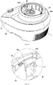
FIG. 5 is a schematic structural diagram of a tray provided in Embodiment 1 of the present invention. -
FIG. 6 is a schematic structural diagram of a body provided in Embodiment 1 of the present invention, with the container assembly locked. -
FIG. 7 is an enlarged view of area A inFIG. 6 . -
FIG. 8 is a schematic diagram of a structure of an upper casing and a supporting block provided in Embodiment 1 of the present invention. -
FIG. 9 is a front view of the container assembly provided in Embodiment 1 of the present invention, with a cover and a main body normally closed. -
FIG. 10 is a schematic diagram of a structure of the container assembly and a part of a detection mechanism provided in Embodiment 1 of the present invention. -
FIG. 11 is a structural diagram of a part of a body provided in Embodiment 1 of the present invention, with a first locking member being in an unlocked position. -
FIG. 12 is a structural diagram of a part of a body provided in Embodiment 1 of the present invention, with a first locking member being in a locked position. -
FIG. 13 is a front view of the container assembly provided inEmbodiment 2 of the present invention, with a cover and a main body of the container assembly being in an abnormally closed state. -
FIG. 14 is a schematic structural diagram of the container assembly provided inEmbodiment 2 of the present invention, with a cover unassembled. -
FIG. 15 is a front view of the container assembly provided inEmbodiment 2 of the present invention, with a cover and a main body being in an abnormally closed state and without assembled with a handle. -
FIG. 16 is a front view of the container assembly provided inEmbodiment 2 of the present invention, with a cover and a main body being in a normal closed state and without assembled with a handle. -
FIG. 17 is a front view of the container assembly provided inEmbodiment 3 of the present invention, with the cover and the main body of the container assembly normally closed. -
FIG. 18 is a schematic structural diagram of a body provided inEmbodiment 3 of the present invention, with the container assembly locked. -
FIG. 19 is an enlarged view of area B inFIG. 18 . -
FIG. 20 is a schematic structural diagram of a first locking member provided inEmbodiment 3 of the present invention. -
FIG. 21 is a schematic structural diagram of a part of the container assembly provided inEmbodiment 3 of the present invention. - 1, body; 11, upper casing; 12, lower casing; 14, tray; 141, groove; 1411, stepped surface; 142, bottom plate; 143, inner plate; 144, outer plate; 15, supporting block;
- 2, container assembly; 21, cover; 211, first inclined surface; 212, block; 22, container; 23, handle; 231, notch; 24, base; 241, limiting portion; 242, protrusion; 25, measuring cup; 26, triggering member; 261, second inclined surface; 27, second reset member;
- 3, steamer assembly;
- 4, first locking member; 41, abutting portion; 42, third inclined surface;
- 5, drive assembly; 51, mounting frame; 52, connecting member;
- 61, second locking member; 62, third reset member;
- 71, adapter; 72, second sensing member; 73, first reset member; 74, second bracket; 75, first sensing member; 76, first bracket; 77, third sensing member.
- The embodiments of the present disclosure will be described in detail below. Examples of the embodiments are shown in the accompanying drawings in which the same or similar reference signs indicate the same or similar elements or elements having the same or similar functions. The embodiments described below with reference to the accompanying drawings are exemplary, and are intended to explain the present disclosure, but should not be construed as limiting the present disclosure.
- In the description of the present disclosure, it should be illustrated that terms indicating orientations or position relationships such as "center", "upper", "lower", "left", "right", "vertical", "horizontal", "inner", "outer", and so on are based on the orientations or position relationships shown in the accompanying drawings, which are used only to facilitate the description of the present disclosure and simplify the description, rather than indicating or implying that the device or element(s) referred to needs to have a specific orientation, be constructed and operated in a specific orientation, and thus the terms are not understood as limiting the present disclosure. Further, the terms "first", "second" are merely illustrative, and are not intended to indicate or imply the importance of the corresponding elements or the number of the technical features. The terms "first position" and "second position" are two different positions.
- In the present disclosure, unless otherwise expressly specified and defined, the terms "mounted", "coupled", "connected" and "fixed" should be interpreted broadly. For example, the connection may be a fixed connection or a detachable connection. The connection may also be a mechanical connection or an electrical connection. Furthermore, the connection may be a direct connection or an indirect connection via an intermedium, an internal connection between the two components or an interaction between the two components. For those of ordinary skill in the art, the specific meanings of the above terms in the present disclosure can be understood according to specific circumstances.
- In the present disclosure, unless otherwise expressly specified and defined, that a first feature is "on" or "under" a second feature may include the first feature directly contacts the second feature, or may include the first feature does not directly contact the second feature but through other features therebetween. Moreover, that the first feature is "over" or "above" the second feature includes the first feature is directly above and obliquely above the second feature, or simply means that a level height of the first feature is higher than that of the second feature. That the first feature is "below" the second feature includes the first feature directly below and obliquely below the second feature, or simply means that the level height of the first feature is less than that of the second feature.
- The technical solutions of the present invention will be further described below in conjunction with the drawings and specific implementations.
- This embodiment provides a food preparation device, which can be used to prepare many kinds of food such as fruit juice, soy milk, jam, dry powder, shaved ice, minced meat and so on.
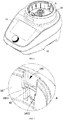
- As shown in
FIG. 1 , the food preparation device includes a body 1, acontainer assembly 2 and asteamer assembly 3. The body 1 serves as a carrier of thecontainer assembly 2 and thesteamer assembly 3, and contains functional components such as a power system, a connection system, and a control system. Thecontainer assembly 2 can be mounted on the body 1, and a knife assembly and a heating assembly are provided in thecontainer assembly 2. The knife assembly is used for further processing of food materials, and the heating assembly is used for heating thecontainer assembly 2. It should be noted that, as an auxiliary device, thesteamer assembly 3 is optional. Thesteamer assembly 3 can be detachably connected to thecontainer assembly 2. When thesteamer assembly 3 is used, water contained in thecontainer assembly 2 is heated by the heating component in thecontainer assembly 2, and steam generated will enter thesteamer assembly 3. - In order to improve the safety performance of the food preparation device, as shown in
FIG. 2 , when thecontainer assembly 2 is placed on the body 1, and when a locking button is pressed, thecontainer assembly 2 and the body 1 will be in a locked state to prevent thecontainer assembly 2 from being separated from the body 1. When thecontainer assembly 2 needs to be removed, an unlocking button is pressed, and thecontainer assembly 2 and the body 1 can be unlocked, so that thecontainer assembly 2 can be removed. - In this embodiment, locking and unlocking of the
container assembly 2 and the body 1 can be achieved by user's controlling the control system with simple operation, which is beneficial to improving using experience. Specifically, the control system includes an instruction input area provided on the body 1 for the user to input a control instruction. Optionally, the instruction input area can be a touch screen, a knob or a button. When the user needs to lock or remove thecontainer assembly 2, the user can input a locking instruction or an unlocking instruction at the instruction input area. The control system will control thedrive assembly 5 to operate according to the instruction to move thefirst locking member 4 to the locked position or the unlocked position, after receiving the instruction. - Specifically, as shown in
FIGS. 3 and4 , thecontainer assembly 2 includes acover 21 and a main body, and the main body includes acontainer 22, ahandle 23 and abase 24. Thecover 21 can be buckled on a top of thecontainer 22, and thehandle 23 is arranged on a side of thecontainer 22, so that the user can move thecontainer assembly 2 conveniently by holding thehandle 23. Thecover 21 is also provided with a measuringcup 25, and the measuringcup 25 can be detachably connected with thecover 21. When the measuringcup 25 is fixed on thecover 21, the measuringcup 25 can be used as a handle ofcover 21 to facilitate the user to open or cover thecover 21. In addition, the measuringcup 25, after being removed from thecover 21, can be used to measure an appropriate amount of food material by a user conveniently. Thecontainer 22 is arranged on thebase 24, and thebase 24 is provided with a structure that cooperates with the body 1 so that the functional components in the body 1 can process the food in thecontainer 22. - The body 1 includes an
upper casing 11 and alower casing 12. After theupper casing 11 and thelower casing 12 are fixed together, a mounting cavity for accommodating the power system and the control system is formed therebetween. Atray 14 is provided on theupper casing 11, and thetray 14 is provided with a mounting groove for carrying thecontainer assembly 2. When thecontainer assembly 2 is arranged on the body 1, a lower end of thecontainer assembly 2 can be inserted into thetray 14, which is beneficial to improving the stability of thecontainer assembly 2. - As shown in
FIG. 4 , thecontainer assembly 2 is provided with a limitingportion 241. The body 1 is movably connected with a first locking member 4 (seeFIG. 11 ), and adrive assembly 5 is arranged in the body 1. Thedrive assembly 5 can drive thefirst locking member 4 to switch between a locked position and an unlocked position. When thecontainer assembly 2 is placed on the body 1, thedrive assembly 5 can drive thefirst locking member 4 to move to the locked position where thefirst locking member 4 can cooperate with the limitingportion 241 to prevent thecontainer assembly 2 from being separated from the body 1, so that the purpose of locking thecontainer assembly 2 and the body 1 is achieved. When thecontainer assembly 2 needs to be removed, thedrive assembly 5 drives thefirst locking member 4 to move to the unlocked position, the limitingportion 241 is disengaged from thefirst locking member 4, and thecontainer assembly 2 is unlocked from the body 1, so that thecontainer assembly 2 can be removed. - In this embodiment, the limiting
portion 241 is provided on a side wall of thebase 24 and protruded therefrom, and thefirst locking member 4 is movably connected with thetray 14. When thecontainer assembly 2 is placed on the body 1, thebase 24 extends into thetray 14 so as to cooperate with thefirst locking member 4. Optionally, thecontainer assembly 2 can be mounted vertically onto thetray 14, and thefirst locking member 4 can move to the upper side of the limitingportion 241 to prevent thecontainer assembly 2 from being pulled out of thetray 14, thereby realizing locking of thecontainer assembly 2 and the body 1. The locking realized by moving thefirst locking member 4 to the upper side of the limitingportion 241 makes the structure simple and the locking effect reliable. - In order to prevent the
container assembly 2 on the body 1 from shaking, when thecontainer assembly 2 is locked with the body 1, thefirst locking member 4 can abut on the upper side of the limitingportion 241 to further limit thecontainer assembly 2. - In other embodiments, the
container assembly 2 can also be assembled into thetray 14 in other directions. For example, an opening is provided on a side of thetray 14, and thecontainer assembly 2 is horizontally assembled into thetray 14 through the opening, as long as thefirst locking member 4 can be moved to a moving trajectory of thecontainer assembly 2 when it is removed. - In other embodiments, the locking can also be achieved by other ways such as engaging the limiting
portion 241 with thefirst locking member 4. - In order to further improve the limiting effect of the
tray 14 on thecontainer assembly 2, when thecontainer assembly 2 is assembled into thetray 14, an outer side wall of thecontainer assembly 2 abuts an inner side wall of the mounting groove, that is, the shape and size of an inner space of the mounting groove can be the same as those of the base of thecontainer assembly 2, which is beneficial to improving the limiting effect of thecontainer assembly 2. - In order to avoid the limiting
portion 241 from interfering with the cooperation between thecontainer assembly 2 and thetray 14, as shown inFIG. 5 , agroove 141 capable of accommodating the limitingportion 241 is provided in an inner side the mounting groove. When thecontainer assembly 2 is mounted from top to bottom, the limitingportion 241 slides down along thegroove 141, so that interference between the limitingportion 241 and thetray 14 can be avoided. After thecontainer assembly 2 is assembled into thetray 14, thedrive assembly 5 drives thefirst locking member 4 to the locked position, so that thefirst locking member 4 extends into thegroove 141 and abuts against a top surface of the limitingportion 241 to achieve locking. - In order to further ensure the locking effect between the
container assembly 2 and the body 1, as shown inFIG. 4 , thecontainer assembly 2 is further provided with aprotrusion 242 which is located above the limitingportion 241. After thecontainer assembly 2 is placed in the body 1, thecontainer assembly 2 drives thefirst locking member 4 to move, so that the abuttingportion 41 slides into thegroove 141 and is located between theprotrusion 242 and the abuttingportion 241, thereby further improving the locking effect of thecontainer assembly 2 and body 1. In addition, by providing theprotrusion 242, the opening at the top of thegroove 141 can be shaded, so that food residues or other sundries can be prevented from falling into thegroove 141, and the appearance of thetray 14 become more beautiful. - In order to reduce the space required for movement of the
first locking member 4 relative to the body 1, in this embodiment, thefirst locking member 4 can rotate along the circumferential direction of thetray 14 and extend into or out of thegroove 141. Thefirst locking member 4 rotates along the circumferential direction of thetray 14, which can reduce the space required for the movement of thefirst locking member 4 and be beneficial to making the structure of the food preparation device more compact, and thus a miniaturized design can be realized. - Specifically, the
tray 14 includes abottom plate 142 and a side plate connected to thebottom plate 142, and the side plate and thebottom plate 142 are enclosed to form a mounting groove used for accommodating the base of thecontainer assembly 2. The side plate may be a double-layer structure formed by a process such as flanging, and the cross-sectional shape of the side plate may be in a U-shape, so that the lockingmember 4 can be arranged in the double-layer structure of the side plate. The side plate includes aninner plate 143 and anouter plate 144 formed by bending theinner plate 143 outward. A cavity is formed between theinner plate 143 and theouter plate 144, and agroove 141 is arranged on theinner plate 143 and communicates with the cavity. Thefirst locking member 4 can be slidably arranged in the cavity. According to the structure configuration of the side plate, thefirst locking member 4 can be hided and thetray 14 can be more beautiful as an appearance member. Thefirst locking member 4 slides along the circumferential direction of the cavity, which requires small space and has a limiting effect on thefirst locking member 4, and thus a space required for thefirst locking member 4 to lock thecontainer assembly 2 and the body 1 can be beneficially reduced. In this embodiment, thetray 14 is integrally formed, which is convenient for processing and is simple in structure. - Optionally, the
first locking member 4 may have an annular structure, so that the stability of thefirst locking member 4 in the annular cavity is better. - Optionally, as shown in
FIGS. 6 and 7 , the abuttingportion 41 is provided on the inner side of thefirst locking member 4. When thedrive assembly 5 drives thefirst locking member 4 to move to the locked position, the abuttingportion 41 on thefirst locking member 4 slides into thegroove 141, and the limitingportion 241 is located below the abuttingportion 41, which will realize the locking of thecontainer assembly 2 and the body 1. - Optionally, a stepped
surface 1411 is provided in thegroove 141. When sliding into thegroove 141, the abuttingportion 41 overlaps on the steppedsurface 1411 to improve the positioning effect of the abuttingportion 41 and thegroove 141 to thecontainer assembly 2. - In order to further improve the locking effect between the
container assembly 2 and the body 1, a plurality of limitingportions 241 may be provided on thecontainer assembly 2. After thecontainer assembly 2 is assembled in the body 1, movement of thefirst locking member 4 makes thefirst locking member 4 abut on the upper side of each limitingportion 241 and the number of force points between the limitingportion 241 and thefirst locking member 4 increased, thereby improving the locking effect of thecontainer assembly 2. The number of the abuttingportions 41 is the same as that of the limitingportions 241 on thecontainer assembly 2, so that the locking effect of thecontainer assembly 2 is improved. - Optionally, the
protrusion 242 is provided above one of the abuttingportions 41, which can form a foolproof structure, so that thecontainer assembly 2 is mounted on the body 1 at a specified angle, thereby improving safety performance. - In this embodiment, the
container assembly 2 is provided with two limitingportions 241 which are respectively provided on both sides of the base. Two abuttingportions 41 are provided on thefirst locking member 4, and each abuttingportion 41 is correspondingly matched with a limitingportion 241 on thecontainer assembly 2. By providing a limitingportion 241 on each of the opposite sides of thecontainer assembly 2, the force exerted on thecontainer assembly 2 in a locked state can be more uniform and the locking effect is better. - In order to prevent the
first locking member 4 from tilting in the cavity, causing the abuttingportion 41 to fail to accurately cooperate with the limitingportion 241, as shown inFIG. 8 , a plurality of supportingblocks 15 are also provided on theupper casing 11. The supporting blocks 15 each supports thefirst locking member 4, so that thefirst locking member 4 is kept to slide horizontally. In order to reduce the wear between the supportingblock 15 and thefirst locking member 4, the supporting surface of the supportingblock 15 may be a smooth arc surface to reduce the contact area between the supporting surface and thefirst locking member 4, thereby reducing friction. - In this embodiment, the food preparation device further includes a detection mechanism which can detect whether the
container assembly 2 and the body 1 are assembled in place, so as to control the operation of thedrive assembly 5 according to the assembled status of thecontainer assembly 2 and the body 1. Specifically, when the detection mechanism detects that thecontainer assembly 2 and the body 1 are assembled in place, and when the user inputs an instruction to lock the body 1 and thecontainer assembly 2 together through the instruction input area on the control system, thedrive assembly 5 drives thefirst locking member 4 to move to the locked position. When the detection mechanism detects that thecontainer assembly 2 and the body 1 have not been assembled in place, and when the user inputs an instruction to lock the body 1 and thecontainer assembly 2 together through the instruction input area on the control system, thedrive assembly 5 will not be started to operate, and the food preparation device can remind the user to check the assembly status of thecontainer assembly 2 and the body 1 in time by means of alarm voice or text display, etc,. - As shown in
FIG. 9 , thecontainer assembly 2 is provided with a triggeringmember 26. As shown inFIG. 10 , the detection mechanism includes asecond sensing member 72. When thecontainer assembly 2 is assembled on the body 1 in place, the triggeringmember 26 can trigger thesecond sensing member 72. After thesecond sensing member 72 detects that thecontainer assembly 2 is assembled on the body 1 in place and the user inputs an instruction to lock the body 1 and thecontainer assembly 2 together, thedrive assembly 5 drives thefirst locking member 4 to move to the locked position to complete the locking of thecontainer assembly 2. In other embodiments, the locking of thecontainer assembly 2 can also be automatically triggered by the detection mechanism. For example, when the detection mechanism detects that thecontainer assembly 2 is mounted on the body 1 and thecover 21 is assembled in place, the detection mechanism sends a detection signal to the control system. The control system will control the action of thedrive assembly 5 according to the detection signal to move thefirst locking member 4 to the locked position without a user's operation, and thus the operation is more convenient and reliable, and the safety performance is good. - In order to facilitate the cooperation between the triggering
member 26 and thesecond sensing member 72, the detection mechanism may also include aresettable adapter 71. Theadapter 71 can be slidably arranged in the cavity of thetray 14. One end of theadapter 71 penetrates through thetray 14 and can abut against the triggeringmember 26, and the other end can cooperate with thesecond sensing member 72 under the drive of the triggeringmember 26. When the triggeringmember 26 does not abut theadapter 71, theadapter 71 can automatically reset and be disengaged from thesecond sensing member 72, and thus thesecond sensing member 72 is not triggered, so that thedrive assembly 5 will not drive thefirst locking member 4 to move to the locked position. - The
second sensing member 72 and theadapter 71 can be arranged in the cavity of thetray 14. By reasonably using the space between theinner plate 143 and theouter plate 144 in thetray 14, the structure of the food preparation device will be more compact. - Specifically, the detection mechanism also includes a
second bracket 74, and both theadapter 71 and thesecond sensing member 72 can be arranged on thesecond bracket 74. Afirst reset member 73 is provided between theadapter 71 and thesecond bracket 74. Two ends of thefirst reset member 73 abut on thesecond bracket 74 and theadapter 71 respectively to drive theadapter 71 to extend out of thetray 14 so as to cooperate with the triggeringmember 26. Optionally, thefirst reset member 73 may be a spring. A contact end is also provided on theadaptor 71. During theadapter 71 is sliding upward and downward, and theadaptor 71 can drive the contact end to abut against thesecond sensing member 72 or disengage from thesecond sensing member 72. - As shown in
FIGS. 11 and12 , thedrive assembly 5 includes a mountingframe 51, a driving member and a connectingmember 52. The driving member is arranged in the mountingframe 51. One end of the connectingmember 52 is connected to thefirst locking member 4, and the other end is connected to the driving member. The driving member causes thefirst locking member 4 to move by driving the connectingmember 52 to move. Optionally, the driving member may be a motor, and the motor is connected to the connectingmember 52 through a transmission mechanism. The transmission mechanism converts the rotation movement of the motor into the sliding movement of the connectingmember 52, thereby driving thefirst locking member 4 to slide relative to the body 1. - Optionally, the transmission mechanism may include a driving gear connected with the motor and a driven gear meshing with the driving gear. The connecting
member 52 may be a screw and be penetrated through the driven gear. The screw is threadedly connected with the driven gear. When rotating, the rotor drives the driving gear to rotate. The driven gear is driven to rotate by the meshing of the driving gear and the driven gear, thereby the screw is driven to move linearly. In other embodiments, the transmission mechanism may be also other types, such as a gear-rack mechanism. - When the
container assembly 2 needs to be removed, the user can input an unlocking instruction at the instruction input area, and thedrive assembly 5 will drive thefirst locking member 4 to move to the unlocked position as shown inFIG. 11 . At this time, the abuttingportion 41 is located outside thegroove 141. Thecontainer assembly 2 can be removed from the body 1 conveniently. When thecontainer assembly 2 is assembled in the body 1, thedrive assembly 5 drives thefirst locking member 4 to move to the locked position shown inFIG. 12 . At this time, the abuttingportion 41 slides into thegroove 141 to cooperate with the limitingportion 241, and thus thecontainer assembly 2 is locked on the body 1. - Optionally, in order to ensure the movement accuracy of the
first locking member 4 driven by thedrive assembly 5, the detection mechanism can also detect the position of thefirst locking member 4 so as to control the start and stop of thedrive assembly 5, so that thefirst locking member 4 moves to the unlocked position or the locked position accurately. - Specifically, the detection mechanism further includes a
first sensing member 75, afirst bracket 76 and athird sensing member 77. Thefirst sensing member 75 is mounted on thefirst bracket 76, and thethird sensing member 77 is mounted on the mountingframe 51. - When the
container assembly 2 is locked, thedrive assembly 5 drives thefirst locking member 4 to move. When thefirst locking member 4 moves to the locked position, as shown inFIG. 12 , thefirst locking member 4 can trigger thefirst sensing member 75, and then thedrive assembly 5 is controlled to stop, so as to stabilize thefirst locking member 4 at the locked position. When thecontainer assembly 2 needs to be unlocked, as shown inFIG. 11 , thedrive assembly 5 drives thefirst locking member 4 to move to the unlocked position, so that thefirst locking member 4 can trigger thethird sensing member 77, and then thedrive assembly 5 is controlled to stop, so as to stabilize thefirst locking member 4 at the unlocked position. By providing thefirst sensing member 75 and thethird sensing member 77, the position accuracy of thefirst locking member 4 can be ensured, thereby ensuring the locking and unlocking effect of thecontainer assembly 2. - Optionally, the
first sensing member 75, thesecond sensing member 72, and thethird sensing member 77 may all be micro switches, which are triggered by pressing a spring sheet of the micro switch. - In other embodiments, the
first sensing member 75, thesecond sensing member 72, and thethird sensing member 77 may also be other types such as contact sensors or proximity sensors to implement the above functions. - Optionally, the control system of the food preparation device may be electrically connected to the detection mechanism. When the spring sheet of the micro switch is triggered, the micro switch obtains the position information of the
first locking member 4 and the mounting state of thecontainer assembly 2 on the body 1, and transmits this information to the control system. The control system controls thedrive assembly 5 to start or stop according to the received information. - This embodiment provides a food preparation device. The difference of the food preparation device in
embodiment 2 from that in embodiment 1 is that the detection mechanism can detect whether thecover 21 and thecontainer 22 are closed in place or not, so as to avoid thecover 21 or the food materials in thecontainer 22 from being thrown out due to the screwing-loosening of thecover 21 when the food preparation device is operating, and thus the safety performance of the food preparation device is improved. - Specifically, when the
cover 21 and thecontainer 22 in thecontainer assembly 2 mounted on the body 1 are closed in place, the triggeringmember 26 can trigger thesecond sensing member 72 in the body 1; otherwise, the triggeringmember 26 cannot trigger thesecond sensing member 72. Thus, thesensor 72 determines whether thecover 21 and thecontainer 22 are closed in place. - When the
cover 21 and thecontainer 22 are closed in place, the triggeringmember 26 extends beyond thehandle 23 to a longer length, and the triggeringmember 26 can trigger thesecond sensing member 72 on the body 1 to generate the information that thecover 21 has been mounted on thecontainer 22 in place. As shown inFIG. 13 , when thecover 21 and thecontainer 22 are not closed in place, the triggeringmember 26 extends beyond thehandle 23 to a short length, and the triggeringmember 26 cannot trigger thesecond sensing member 72 on the body 1, such that thecover 21 is determined to be abnormally covered on thecontainer 22. - In order to enable the triggering
member 26 to move with the cooperating state of thecover 21 and thecontainer 22, as shown inFIG. 14 , the triggeringmember 26 is provided inside thehandle 23, and thehandle 23 is provided with anotch 231. As shown inFIGS. 15 and 16 , thecover 21 is provided with a firstinclined surface 211, and the triggeringmember 26 is resetably arranged on thecontainer 22. The triggeringmember 26 is provided with a secondinclined surface 261. Thecover 21 covers thecontainer 22 in a rotating manner. When thecover 21 is cover on thecontainer 22 in a rotating manner, the firstinclined surface 211 on thecover 21 can be slidably matched with the secondinclined surface 261 on the triggeringmember 26 through thenotch 231, so as to drive the triggeringmember 26 to move. - As shown in
FIG. 15 , when thecover 21 and thecontainer 22 are abnormally closed, the triggeringmember 26 is retracted into thehandle 23 under the action of thesecond reset member 27. As shown inFIG. 16 , during a process that thecover 21 rotates relative to thecontainer 22 to cover the container, the firstinclined surface 211 on thecover 21 can be slidably matched with the secondinclined surface 261 on the triggeringmember 26 and push the triggeringmember 26 to slide downwards, so that the lower end of the triggeringmember 26 gradually extends out of thehandle 23 so as to abut against theadapter 71. - In order to prevent the user from removing the
cover 21 from thecontainer assembly 2 during the operation of the food preparation device, which may cause a safety accident, in this embodiment, a food preparation device is provided. The difference of the food preparation device inembodiment 3 from those in the above embodiments is that when thecontainer assembly 2 is locked with the body 1 together, thecover 21 can be locked with the main body together, which improves the safety performance of the food preparation device. - Specifically, as shown in
FIG. 17 , thecontainer assembly 2 is provided with asecond locking member 61 which is movable. When thefirst locking member 4 is moved to the locked position, thefirst locking member 4 can drive thesecond locking member 61 to move, so as to lock thecover 21 on the main body. - Optionally, the
second locking member 61 can also be arranged in thehandle 23. Thesecond locking member 61 is slidably connected with thecontainer 22 in the vertical direction and has a reset function. When thefirst locking member 4 is moved to the unlocked position, thesecond locking member 61 will automatically be reset and the locking of thecover 21 and thecontainer 22 is released, so that thecontainer assembly 2 can be opened. Specifically, thesecond locking member 61 and thecontainer 22 are connected by athird reset member 62. Optionally, thethird reset member 62 may be a spring. - In this embodiment, the
first locking member 4 can drive thesecond locking member 61 to move upwards so as to lock thecover 21. In order to make thefirst locking member 4 drive thesecond locking member 61, as shown inFIGS. 18-20 , thefirst locking member 4 is provided with a thirdinclined surface 42 which can slidably cooperate the lower end of thesecond locking member 61. - When the
first locking member 4 is moving to the locked position, the thirdinclined surface 42 gradually slides into thegroove 141 and cooperates with the lower end of thesecond locking member 61 extending into thegroove 141. The thirdinclined surface 42 gradually decreases in height along the direction of sliding into thegroove 141, so that thesecond locking member 61 slides upwards when sliding along the thirdinclined surface 42, so that thesecond locking member 61 achieves the locking of thecover 21. - In order that the
second locking member 61 is able to lock thecover 21 after being raised, as shown inFIG. 21 , ablock 212 is provided at the bottom of thecover 21. In the state that thecover 21 and thecontainer 22 are turned to be tightened, and after thesecond locking member 61 is slid upwards, the top end of thesecond locking member 61 abuts against a side of theblock 212 facing away from the screwing-tightening direction of thecover 21, so that thecover 21 is prevented from rotating in the screwing-loosening direction relative to thecontainer 22, and the purpose of locking thecover 21 is achieved. - After being reset, the
second locking member 61 slides down and no longer abuts against theblock 212, and the locking ofcover 21 and thecontainer 22 is released. - The above contents are only preferred embodiments of the present invention. For those of ordinary skill in the art, according to the idea of the present invention, there will be changes in the specific implementation and the scope of application. The contents of this specification should not be construed as a limitation to the present invention.
Claims (10)
- A food preparation device, comprising a body (1) and a container assembly (2), characterized in that the food preparation device further comprises a drive assembly (5) and a first locking member (4) capable of rotating along a circumferential direction of the body (1); the drive assembly (5) is configured to drive the first locking member (4) to move to a locked position or an unlocked position;
when the first locking member (4) is in the locked position, the first locking member (4) locks the container assembly (2) on the body (1); when the first locking member (4) is in the unlocked position, the container assembly (2) can be separated from the body (1). - The food preparation device according to claim 1, wherein the container assembly (2) is mounted vertically onto the body (1); the container assembly (2) is provided with a convex limiting portion (241) on its side wall, and the first locking member (4) is provided with an abutting portion (41); and the drive assembly (5) is capable of driving the abutting portion (41) to extend into or out of an upper part of the limiting portion (241) during the rotation of the first locking member (4).
- The food preparation device according to claim 2, wherein the body (1) is provided with a mounting groove for accommodating a bottom of the container assembly (2), and an inner side of the mounting groove is provided with a groove (141) capable of accommodating the limiting portion (241); and the abutting portion (41) is capable of extending into or out of the groove (141) along the circumferential direction of the body (1).
- The food preparation device according to claim 1, wherein the drive assembly (5) comprises:a connecting member (52), and the connecting member (52) is connected with the first locking member (4) with one end; anda driving member arranged in the body (1), and the driving member is configured to drive the connecting member (52) to move.
- The food preparation device according to any one of claims 1-4, wherein the food preparation device further comprises:a detection mechanism configured to detect whether the first locking member (4) is moved to a designated position to control starting or stopping of the drive assembly (5);preferably, the detection mechanism comprises:a first sensing member (75) configured to be capable of being triggered by the first locking member (4) in the locked position; anda third sensing member (77) configured to be capable of being triggered by the first locking member (4) in the unlocked position.
- The food preparation device according to any one of claims 1 to 4, wherein the food preparation device further comprises:a detection mechanism configured to detect a mounting state of the container assembly (2) and the body (1), and control working of the drive assembly (5) according to a detection result;preferably, the detection mechanism comprises:
a second sensing member (72), wherein the container assembly (2) is provided with a triggering member (26); and when the container assembly (2) is placed on the body (1), the triggering member (26) triggers the second sensing member (72) to make the drive assembly (5) drive the first locking member (4) to move to the locked position. - The food preparation device according to claim 6, wherein the container assembly (2) comprises a main body and a cover (21) being rotatably matched with the main body; and when the cover (21) and the main body rotate to a closed position, the triggering member (26) is capable of triggering the second sensing member (72).
- The food preparation device according to claim 7, wherein the triggering member (26) is slidably connected to the body and has a reset function;
preferably, the cover (21) is rotatably matched with the main body, a first inclined surface (211) is provided on the cover (21), and a second inclined surface (261) is provided on the triggering member (26);
when the cover (21) rotates in a screwing-tightening direction relative to the main body, the first inclined surface (211) slides along the second inclined surface (261) and pushes the triggering member (26) to slide, so that the triggering member (26) is capable of triggering the second sensing member (72);
when the cover (21) rotates in a screwing-loosening direction relative to the main body, the first inclined surface (211) and the second inclined surface (261) are gradually separated from each other, and the triggering member (26) is reset. - The food preparation device according to claim 7, wherein when the container assembly (2) is locked with the body (1), the cover (21) is configured to be locked with the main body;
preferably, the container assembly (2) is movably connected with a second locking member (61), and when the first locking member (4) moves to the locked position, the first locking member (4) drives the second locking member (61) to move to lock the cover (21);
preferably, the second locking member (61) is slidably connected to the main body and has a reset function, and when the second locking member (61) is reset, the cover (21) is unlocked from the main body. - The food preparation device according to claim 9, wherein the cover (21) is rotatably matched with the main body, a block (212) is provided at a bottom of the cover (21), and the first locking member (4) drives the second locking member (61) to extend into the bottom of the cover (21) and abut the block (212) to prevent the cover (21) from rotating in a screwing-loosening direction relative to the main body;
preferably, a third inclined surface (42) is provided on the first locking member (4), and when the first locking member (4) moves to the locked position, the second locking member (61) slides along the third inclined surface (42).
Applications Claiming Priority (2)
| Application Number | Priority Date | Filing Date | Title |
|---|---|---|---|
| CN201910785229.3A CN110448201B (en) | 2019-08-23 | 2019-08-23 | Food processor |
| PCT/CN2019/114113 WO2021035929A1 (en) | 2019-08-23 | 2019-10-29 | Food processor |
Publications (2)
| Publication Number | Publication Date |
|---|---|
| EP3821773A1 true EP3821773A1 (en) | 2021-05-19 |
| EP3821773A4 EP3821773A4 (en) | 2021-11-10 |
Family
ID=68488773
Family Applications (1)
| Application Number | Title | Priority Date | Filing Date |
|---|---|---|---|
| EP19940167.0A Pending EP3821773A4 (en) | 2019-08-23 | 2019-10-29 | Food processor |
Country Status (3)
| Country | Link |
|---|---|
| EP (1) | EP3821773A4 (en) |
| CN (1) | CN110448201B (en) |
| WO (1) | WO2021035929A1 (en) |
Cited By (1)
| Publication number | Priority date | Publication date | Assignee | Title |
|---|---|---|---|---|
| WO2023281150A1 (en) * | 2021-07-09 | 2023-01-12 | Cecotec Research and Development S.L. | Electromechanical locking device for a food processor |
Families Citing this family (3)
| Publication number | Priority date | Publication date | Assignee | Title |
|---|---|---|---|---|
| CN114668320B (en) * | 2020-12-24 | 2024-03-12 | 莱克电气绿能科技(苏州)有限公司 | Food processor |
| CN114305168B (en) * | 2021-12-02 | 2023-12-12 | 广东纯米电器科技有限公司 | food processor |
| CN114534879A (en) * | 2022-02-22 | 2022-05-27 | 广东力然电器实业有限公司 | Meat grinder with automatic meat grinding joint locking function |
Family Cites Families (12)
| Publication number | Priority date | Publication date | Assignee | Title |
|---|---|---|---|---|
| JP4526155B2 (en) * | 2000-04-24 | 2010-08-18 | 株式会社ニッセー | Multi-function extractor |
| CN1465322A (en) * | 2002-07-04 | 2004-01-07 | 乐金电子(天津)电器有限公司 | Fault open prevention device for electric pressure cooker |
| CN201139425Y (en) * | 2008-01-18 | 2008-10-29 | 佛山市顺德区爱德实业有限公司 | Electric pressure cooker capable of automatically locking |
| DE102011000219A1 (en) * | 2010-03-31 | 2011-10-06 | Vorwerk & Co. Interholding Gmbh | Electric motor driven food processor, as well as preparation vessel |
| CH704759A1 (en) * | 2011-03-29 | 2012-10-15 | Pi Design Ag | Container closure. |
| DE102014112267A1 (en) * | 2014-08-27 | 2016-03-03 | Vorwerk & Co. Interholding Gmbh | Food processor with locking device |
| CN105662127B (en) * | 2014-12-08 | 2018-01-02 | (株)酷晨 | Voltage force pot for cooking rice, automatic locking apparatus, automatic pressure lock function control method |
| CN205041278U (en) * | 2015-09-30 | 2016-02-24 | 浙江绍兴苏泊尔生活电器有限公司 | Stirring cup and have its cooking machine |
| CN105996827A (en) * | 2016-07-23 | 2016-10-12 | 中山市伊丝顿电器有限公司 | Wall-breaking food processer |
| CN108201340B (en) * | 2016-12-20 | 2020-09-15 | 佛山市顺德区美的电热电器制造有限公司 | Lid opening and closing mechanism and cooking utensil |
| CN109984588B (en) * | 2018-01-03 | 2021-12-17 | 佛山市顺德区美的电热电器制造有限公司 | Cooking utensil and upper cover subassembly thereof |
| CN108567304B (en) * | 2018-06-15 | 2023-07-21 | 莱克电气股份有限公司 | Food processing device |
-
2019
- 2019-08-23 CN CN201910785229.3A patent/CN110448201B/en active Active
- 2019-10-29 WO PCT/CN2019/114113 patent/WO2021035929A1/en unknown
- 2019-10-29 EP EP19940167.0A patent/EP3821773A4/en active Pending
Cited By (2)
| Publication number | Priority date | Publication date | Assignee | Title |
|---|---|---|---|---|
| WO2023281150A1 (en) * | 2021-07-09 | 2023-01-12 | Cecotec Research and Development S.L. | Electromechanical locking device for a food processor |
| ES2932444A1 (en) * | 2021-07-09 | 2023-01-19 | Cecotec Res And Development S L | ELECTROMECHANICAL INTERLOCK DEVICE FOR KITCHEN ROBOT (Machine-translation by Google Translate, not legally binding) |
Also Published As
| Publication number | Publication date |
|---|---|
| EP3821773A4 (en) | 2021-11-10 |
| WO2021035929A1 (en) | 2021-03-04 |
| CN110448201A (en) | 2019-11-15 |
| CN110448201B (en) | 2021-07-09 |
Similar Documents
| Publication | Publication Date | Title |
|---|---|---|
| EP3821773A1 (en) | Food processor | |
| EP3821774A1 (en) | Food processor | |
| US6776086B1 (en) | Safety switch for a food processor | |
| US4095751A (en) | Slicing and shredding apparatus | |
| EP2005867A1 (en) | Kitchen apparatus, stabilizer and arm assembly | |
| CN107468098B (en) | Food stirring cup with double protection switches and stirrer | |
| US3635270A (en) | Combination can opener and slicing shredding appliance | |
| JP4015967B2 (en) | Food preparation device | |
| CN210748879U (en) | Food processor | |
| JP4269483B2 (en) | Electric cooker | |
| CN211459909U (en) | Food processor | |
| CN213850242U (en) | Food processing machine | |
| CN219374453U (en) | Food processor | |
| CN208822548U (en) | Cup body component and food processor | |
| CN217090454U (en) | Double-connecting-rod structure of juicer | |
| JPS6115537B2 (en) | ||
| CN219249932U (en) | Multifunctional cooking equipment | |
| CN216776785U (en) | Pot cover locking mechanism of cooking machine | |
| CN211432483U (en) | Simple structure's portable food preparation machine | |
| CN219877988U (en) | Cooking equipment for frying and roasting with less oil | |
| CN217696121U (en) | Push plate structure and cooking utensil with same | |
| JP2532595B2 (en) | Heating cooker | |
| CN219835514U (en) | Capsule coffee machine head structure with retractable needles and capsule coffee machine | |
| CN211243022U (en) | Portable food preparation machine that machining efficiency is high | |
| CN212521478U (en) | Juicer accessory and cooking preparation household appliance comprising same |
Legal Events
| Date | Code | Title | Description |
|---|---|---|---|
| STAA | Information on the status of an ep patent application or granted ep patent |
Free format text: STATUS: UNKNOWN |
|
| STAA | Information on the status of an ep patent application or granted ep patent |
Free format text: STATUS: THE INTERNATIONAL PUBLICATION HAS BEEN MADE |
|
| PUAI | Public reference made under article 153(3) epc to a published international application that has entered the european phase |
Free format text: ORIGINAL CODE: 0009012 |
|
| STAA | Information on the status of an ep patent application or granted ep patent |
Free format text: STATUS: REQUEST FOR EXAMINATION WAS MADE |
|
| 17P | Request for examination filed |
Effective date: 20210209 |
|
| AK | Designated contracting states |
Kind code of ref document: A1 Designated state(s): AL AT BE BG CH CY CZ DE DK EE ES FI FR GB GR HR HU IE IS IT LI LT LU LV MC MK MT NL NO PL PT RO RS SE SI SK SM TR |
|
| A4 | Supplementary search report drawn up and despatched |
Effective date: 20211013 |
|
| RIC1 | Information provided on ipc code assigned before grant |
Ipc: A47J 27/04 20060101ALI20211006BHEP Ipc: A47J 19/02 20060101ALI20211006BHEP Ipc: A47J 43/07 20060101ALI20211006BHEP Ipc: A47J 43/046 20060101AFI20211006BHEP |
|
| DAV | Request for validation of the european patent (deleted) | ||
| DAX | Request for extension of the european patent (deleted) | ||
| STAA | Information on the status of an ep patent application or granted ep patent |
Free format text: STATUS: EXAMINATION IS IN PROGRESS |
|
| 17Q | First examination report despatched |
Effective date: 20231004 |