EP3821171B1 - Method of heat transfer and associated device - Google Patents
Method of heat transfer and associated device Download PDFInfo
- Publication number
- EP3821171B1 EP3821171B1 EP19769227.0A EP19769227A EP3821171B1 EP 3821171 B1 EP3821171 B1 EP 3821171B1 EP 19769227 A EP19769227 A EP 19769227A EP 3821171 B1 EP3821171 B1 EP 3821171B1
- Authority
- EP
- European Patent Office
- Prior art keywords
- solid particles
- metal product
- anyone
- heat
- slab
- Prior art date
- Legal status (The legal status is an assumption and is not a legal conclusion. Google has not performed a legal analysis and makes no representation as to the accuracy of the status listed.)
- Active
Links
Images


Classifications
-
- F—MECHANICAL ENGINEERING; LIGHTING; HEATING; WEAPONS; BLASTING
- F22—STEAM GENERATION
- F22B—METHODS OF STEAM GENERATION; STEAM BOILERS
- F22B31/00—Modifications of boiler construction, or of tube systems, dependent on installation of combustion apparatus; Arrangements or dispositions of combustion apparatus
- F22B31/0007—Modifications of boiler construction, or of tube systems, dependent on installation of combustion apparatus; Arrangements or dispositions of combustion apparatus with combustion in a fluidized bed
-
- F—MECHANICAL ENGINEERING; LIGHTING; HEATING; WEAPONS; BLASTING
- F28—HEAT EXCHANGE IN GENERAL
- F28C—HEAT-EXCHANGE APPARATUS, NOT PROVIDED FOR IN ANOTHER SUBCLASS, IN WHICH THE HEAT-EXCHANGE MEDIA COME INTO DIRECT CONTACT WITHOUT CHEMICAL INTERACTION
- F28C3/00—Other direct-contact heat-exchange apparatus
- F28C3/10—Other direct-contact heat-exchange apparatus one heat-exchange medium at least being a fluent solid, e.g. a particulate material
- F28C3/12—Other direct-contact heat-exchange apparatus one heat-exchange medium at least being a fluent solid, e.g. a particulate material the heat-exchange medium being a particulate material and a gas, vapour, or liquid
- F28C3/16—Other direct-contact heat-exchange apparatus one heat-exchange medium at least being a fluent solid, e.g. a particulate material the heat-exchange medium being a particulate material and a gas, vapour, or liquid the particulate material forming a bed, e.g. fluidised, on vibratory sieves
-
- B—PERFORMING OPERATIONS; TRANSPORTING
- B22—CASTING; POWDER METALLURGY
- B22D—CASTING OF METALS; CASTING OF OTHER SUBSTANCES BY THE SAME PROCESSES OR DEVICES
- B22D30/00—Cooling castings, not restricted to casting processes covered by a single main group
-
- C—CHEMISTRY; METALLURGY
- C21—METALLURGY OF IRON
- C21D—MODIFYING THE PHYSICAL STRUCTURE OF FERROUS METALS; GENERAL DEVICES FOR HEAT TREATMENT OF FERROUS OR NON-FERROUS METALS OR ALLOYS; MAKING METAL MALLEABLE, e.g. BY DECARBURISATION OR TEMPERING
- C21D1/00—General methods or devices for heat treatment, e.g. annealing, hardening, quenching or tempering
- C21D1/62—Quenching devices
- C21D1/63—Quenching devices for bath quenching
- C21D1/64—Quenching devices for bath quenching with circulating liquids
-
- C—CHEMISTRY; METALLURGY
- C21—METALLURGY OF IRON
- C21D—MODIFYING THE PHYSICAL STRUCTURE OF FERROUS METALS; GENERAL DEVICES FOR HEAT TREATMENT OF FERROUS OR NON-FERROUS METALS OR ALLOYS; MAKING METAL MALLEABLE, e.g. BY DECARBURISATION OR TEMPERING
- C21D11/00—Process control or regulation for heat treatments
- C21D11/005—Process control or regulation for heat treatments for cooling
-
- F—MECHANICAL ENGINEERING; LIGHTING; HEATING; WEAPONS; BLASTING
- F22—STEAM GENERATION
- F22B—METHODS OF STEAM GENERATION; STEAM BOILERS
- F22B1/00—Methods of steam generation characterised by form of heating method
- F22B1/02—Methods of steam generation characterised by form of heating method by exploitation of the heat content of hot heat carriers
- F22B1/04—Methods of steam generation characterised by form of heating method by exploitation of the heat content of hot heat carriers the heat carrier being hot slag, hot residues, or heated blocks, e.g. iron blocks
-
- F—MECHANICAL ENGINEERING; LIGHTING; HEATING; WEAPONS; BLASTING
- F22—STEAM GENERATION
- F22B—METHODS OF STEAM GENERATION; STEAM BOILERS
- F22B31/00—Modifications of boiler construction, or of tube systems, dependent on installation of combustion apparatus; Arrangements or dispositions of combustion apparatus
- F22B31/0007—Modifications of boiler construction, or of tube systems, dependent on installation of combustion apparatus; Arrangements or dispositions of combustion apparatus with combustion in a fluidized bed
- F22B31/0061—Constructional features of bed cooling
-
- F—MECHANICAL ENGINEERING; LIGHTING; HEATING; WEAPONS; BLASTING
- F28—HEAT EXCHANGE IN GENERAL
- F28F—DETAILS OF HEAT-EXCHANGE AND HEAT-TRANSFER APPARATUS, OF GENERAL APPLICATION
- F28F19/00—Preventing the formation of deposits or corrosion, e.g. by using filters or scrapers
- F28F19/01—Preventing the formation of deposits or corrosion, e.g. by using filters or scrapers by using means for separating solid materials from heat-exchange fluids, e.g. filters
-
- F—MECHANICAL ENGINEERING; LIGHTING; HEATING; WEAPONS; BLASTING
- F28—HEAT EXCHANGE IN GENERAL
- F28F—DETAILS OF HEAT-EXCHANGE AND HEAT-TRANSFER APPARATUS, OF GENERAL APPLICATION
- F28F23/00—Features relating to the use of intermediate heat-exchange materials, e.g. selection of compositions
-
- C—CHEMISTRY; METALLURGY
- C21—METALLURGY OF IRON
- C21D—MODIFYING THE PHYSICAL STRUCTURE OF FERROUS METALS; GENERAL DEVICES FOR HEAT TREATMENT OF FERROUS OR NON-FERROUS METALS OR ALLOYS; MAKING METAL MALLEABLE, e.g. BY DECARBURISATION OR TEMPERING
- C21D1/00—General methods or devices for heat treatment, e.g. annealing, hardening, quenching or tempering
- C21D1/34—Methods of heating
- C21D1/53—Heating in fluidised beds
-
- Y—GENERAL TAGGING OF NEW TECHNOLOGICAL DEVELOPMENTS; GENERAL TAGGING OF CROSS-SECTIONAL TECHNOLOGIES SPANNING OVER SEVERAL SECTIONS OF THE IPC; TECHNICAL SUBJECTS COVERED BY FORMER USPC CROSS-REFERENCE ART COLLECTIONS [XRACs] AND DIGESTS
- Y02—TECHNOLOGIES OR APPLICATIONS FOR MITIGATION OR ADAPTATION AGAINST CLIMATE CHANGE
- Y02P—CLIMATE CHANGE MITIGATION TECHNOLOGIES IN THE PRODUCTION OR PROCESSING OF GOODS
- Y02P10/00—Technologies related to metal processing
- Y02P10/10—Reduction of greenhouse gas [GHG] emissions
- Y02P10/122—Reduction of greenhouse gas [GHG] emissions by capturing or storing CO2
Definitions
- the invention is related to a method of heat transfer from a hot flat metal product to a medium and to the associated device.
- Patent WO 81/02585 describes a method in which hot metal bars are circulating in a fluidized bed, said fluidized bed capturing heat released by the bars. This method is described for bars and is not suitable for larger products such as slabs.
- Patent US 4,351,633 describes a method in which slabs are stacked and sent to a cooling chamber wherein air circulates and capture the heat released by the slab through thermal convection. Heated air is then sent to a series of heat exchangers designed to produce steam for further applications. Convection means require an air circulation device, such as a fan, which consumes a lot of energy and thus decrease the process yield. Moreover, this method implies a big size equipment and a long residence time of the slabs within the equipment because of a low heat exchange coefficient between air and slab.
- Patent GB 1 528 863 describes a cooling method of steel products wherein a slab is placed in a slot between two cooling walls made of boiler tubes wherein water is circulating.
- the heat released by the slab primarily through radiation allows heating of the circulating water in the boiler tubes which at the end of the tube is turned into steam. Once reaching the appropriate temperature the slab is removed from the slot and conveyed to the next process step.
- This method requires a long cooling time and the heat recovery rate is quite low with a lot of heat losses.
- Patent FR 2 996 470 describes a heat capture method by conduction wherein a slab is continuously moving within a chamber which is thermally insulated the chamber comprising radiation and conductions means to recover heat released by the slab such as copper pipes wherein water circulates, those means are located above and below the slabs.
- This method requires a big size equipment and a big investment to get a fully insulated chamber. There is so a need for a method which overcome the above-mentioned drawbacks.
- the method according to the invention allows the transfer of heat from a hot flat metal product to a medium with a high heat recovery rate in a reduced time without detrimental impact on the product, for example on its flatness. Moreover, the method according to the invention requires an equipment which can be easily installed in an existing plant with few invest.
- the method according to the invention allows performing a homogeneous cooling of the metal product and has no impact on the quality of the metal product. For example, it neither involves detrimental chemical impact on the metal product, nor has any physical impact on its surface which could create surface defects.
- the invention is also related to a device for heat transfer according to independent claim 14.
- a slab 3 which is an example of a flat metal product.
- Said slab 3 has a parallelepipedal shape and comprises a top 3a and a bottom broad face, two small faces 3b and two edges 3c.
- the broad faces define the width W and the length L of the slab, said width W being usually comprised between 700 and 2 500 mm, the length L between 5 000 and 15 000 mm and the thickness T of the slab is usually comprised between 150 and 350 mm.
- a flat product can be defined as a parallelepiped wherein the smallest dimension (e.g. the thickness T) is negligible compared to the others (e.g. the length L), for example the smallest dimension being at least smaller than the biggest dimension of a factor 15.
- the broad faces of the parallelepiped are the faces which do not include the smallest dimension.
- Another example of a flat product is a plate or heavy plate.
- FIG 2 is illustrated a device 1 to perform a heat transfer method according to the invention.
- This device 1 comprises a chamber 2 wherein hot flat metal products, such as a slab 3, is placed.
- the chamber 2 may be a closed chamber with a closable opening through which hot flat metal products maybe conveyed, but it could also have an open roof or any configuration suitable for hot flat metal products conveying.
- Hot flat metal products 3 may be conveyed inside the chamber 2 by a rolling conveyor or maybe placed inside the chamber 2 by pick up means, such as cranes or any suitable pick up mean.
- the chamber 2 is preferentially able to receive more than one flat product 3.
- the chamber 2 contains solid particles and comprises gas injection means 4, gas being injected to fluidize the solid particles and create a fluidized bed of solid particles 5 in a bubbling regime, the solid fluidized particles circulating along a circulation direction (D).
- the hot flat metal products 3 are placed into the chamber 2 on support means so that their broad face 3a is parallel to the direction (D) of circulation of the fluidized particles.
- the direction (D) is vertical and the slab 3 is placed on the support along its edge 3c so that its broad face 3a is parallel to the vertical direction. This allows to promote heat transfer efficiency but also to avoid deformation of the product.
- the hot flat metal products have a temperature above 400°C when placed into the chamber 2 and are for example slabs or plates and maybe made of steel.
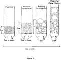
- Fluidization is the operation by which solid particles are transformed into a fluidlike state through suspension in a gas or a liquid.
- behavior of the particles is different.
- gas-solid systems as the one of the invention, with an increase in flow velocity beyond minimum fluidization, large instabilities with bubbling and channeling of gases are observed. At higher velocities, agitation becomes more violent and the movement of solids become more vigorous.
- the bed does not expand much beyond its volume at minimum fluidization.
- the fluidized bed is in a bubbling regime, which is the required regime for the invention in order to have a good circulation of the solid particles and a homogeneous temperature of the fluidized bed.
- Gas velocity to be applied to get a given regime depends on several parameters like the kind of gas used, the size and density of the particles or the size of the chamber 2. This can be easily managed by a man skilled in the art.
- the gas can be nitrogen or an inert gas such as argon or helium and in a preferred embodiment, air. It is preferably injected at a velocity between 5 and 30cm/s which requires a low ventilation power and so a reduced energy consumption. In a preferred embodiment the injection flow rate of gas is controlled to monitor the cooling rate of the hot metal products 3. This may be advantageous for metal products whose quality is impacted by cooling rate, such as steel, but also be advantageous for the plant to regulate production.
- the solid particles preferentially have a heat capacity comprised between 500 and 2000 J/Kg/K. Their density is preferentially comprised between 1400 and 4000 kg/m 3 . They maybe ceramic particles such as SiC, Alumina or steel slag. They may be made of glass or any other solid materials stable up to 1000°C. They preferably have a size comprised between 30 and 300 ⁇ m. These particles are preferably inert to prevent any reaction with the hot metal product 3.
- the device 1 further comprises at least one heat exchanger 6 wherein a transfer medium is circulating, the heat exchanger being in contact with the fluidized bed 5.
- This heat exchanger may be composed, as illustrated in figure 1 , of a first pipe 61 wherein a cool transfer medium 10 is circulating so as to bring it to the heat exchanger, a second pipe 62 wherein heated transfer medium 11 is recovered and third pipes 63 going connecting the first pipe 61 and the second pipe 62 and going through the chamber 2 and the fluidized bed 5 wherein the cool transfer medium 11 from the first pipe 61 is heated.
- the hot metal products 3 are immersed into the fluidized bed 5 of solid particles, solid particles which are then able to capture the heat released by the hot metal products 3.
- the solid particles are kept in motion by the injection of gas by the injection means 4 and come in contact with the heat exchanger 6 where they release the captured heat to the transfer medium circulating within.
- the flow rate of transfer medium inside the heat exchanger can be regulated to control the cooling rate, indeed the more medium is circulating inside the heat exchanger, the more heat is released from the solid particles.
- the transfer medium 10 circulating in the heat exchanger is pressurized water which, once heated by the heat released by the fluidized solid particles, is turned into steam 11.
- Pressurized water may have an absolute pressure between 1 and 30 Bar. Pressurized water may then be turned into steam by a flash drum 7 or any other suitable steam production equipment. Preferentially the water remains liquid inside the heat exchanger.
- the produced steam 11 may then be reused within the metal production plant by injection within the plant steam network, for hydrogen production for example or for RH vacuum degassers or CO 2 gas separation units in the case of a steel plant. Having both steam reuse plant and metal product manufacturing plant within the same network of plant allows to improve the overall energy efficiency of said network.
- the transfer medium 10 circulating in the heat exchanger may also be air or molten salts having preferably a phase change between 400 and 800°C which allow to store the capture heat.
- the transfer medium 10 may comprises nanoparticles to promote heat transfer.
- the metal product 3 may comprise scale particles on its surfaces. By chemical or physical interaction with the solid fluidized particles, those scale particles may be removed from the metal product 3 and drop down at the bottom of the fluidized bed.
- the equipment 1 is provided with a scale removal device, such as a removable metallic grid to frequently remove the scale particles from the fluidized bed.
- metal products may be cooled down from 800°C to 400°C in less than 60 minutes.
- the method according to the invention may be performed at the exit of a casting plant or at the exit of a levelling or rolling stand.
- the method according to the invention allows a fast and homogeneous cooling of the metal product while recovering at least 90% of the heat released by the metal products without deformation of said product.
- the device according to the invention is quite compact and can be adapted to the available space. As air tightness is not required it does not require a big investment nor a high level of maintenance to remain efficient.
- a heat exchanger as the one illustrated in figure 1 using water as fluid was used for the simulation.
- 2 scenarios were considered, one with an initial slab temperature of 800°C and a cooling up to 400°C and a 2 nd scenario with an initial temperature of 550°C and a final one of 250°C.
- Results are presented in table 1.
- Table 1 T ini (°C)
- T final (°C) Residency time of the slabs Energy recovered (GJ/slab) Steam produced (t/slab) Steam pressure (Bar) 800 400 35 min 7.41 2.25 26 550 250 35 min 4.50 1.385 7
- a heat exchanger as the one illustrated in figure 2 using water as fluid was used for the simulation.
- initial slab temperature is of 800°C and it is cooled up to 400°C.
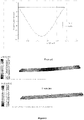
- scenario A the slab is placed in the fluidized bed so that one of its broad face lay down on the support means, its broad faces being thus perpendicular to the direction of circulation of the fluidized particles while in the scenario B it is placed on one of its edges, its broad faces being thus parallel to the direction of circulation of the fluidized particles.
- figure 4 is represented the evolution of temperature with time of one point taken on the top broad face, slab center and bottom broad face. It is clear from the simulation that the bottom and the top broad face don't follow the same thermal path, contrary to what happens with a method according to the invention (both curves are superposed, only one is visible).
- FIG. 5 This an impact on the product, as can be seen on figure 5 .
- This figure represents first the curve of displacement in the vertical direction along the length of the product when cooling with a method according to prior art and a method according to the invention. In the two other pictures this displacement is represented directly on the product and we can see that when using a method according to prior art there is a clear bending of the product which won't come back to its initial flatness.
- the method according to the invention allows thus capturing the heat released by the hot flat metal product without detrimental impact on the product and notably without involving a deformation of said product.
Landscapes
- Engineering & Computer Science (AREA)
- Chemical & Material Sciences (AREA)
- Mechanical Engineering (AREA)
- Physics & Mathematics (AREA)
- Thermal Sciences (AREA)
- General Engineering & Computer Science (AREA)
- Combustion & Propulsion (AREA)
- Crystallography & Structural Chemistry (AREA)
- Materials Engineering (AREA)
- Metallurgy (AREA)
- Organic Chemistry (AREA)
- Sustainable Energy (AREA)
- Sustainable Development (AREA)
- Life Sciences & Earth Sciences (AREA)
- Heat-Exchange Devices With Radiators And Conduit Assemblies (AREA)
- Heat Treatments In General, Especially Conveying And Cooling (AREA)
- Physical Or Chemical Processes And Apparatus (AREA)
- Furnace Details (AREA)
Applications Claiming Priority (2)
| Application Number | Priority Date | Filing Date | Title |
|---|---|---|---|
| PCT/IB2018/055109 WO2020012221A1 (en) | 2018-07-11 | 2018-07-11 | Method of heat transfer and associated device |
| PCT/IB2019/055879 WO2020012378A2 (en) | 2018-07-11 | 2019-07-10 | Method of heat transfer and associated device |
Publications (2)
| Publication Number | Publication Date |
|---|---|
| EP3821171A2 EP3821171A2 (en) | 2021-05-19 |
| EP3821171B1 true EP3821171B1 (en) | 2022-08-31 |
Family
ID=63244640
Family Applications (1)
| Application Number | Title | Priority Date | Filing Date |
|---|---|---|---|
| EP19769227.0A Active EP3821171B1 (en) | 2018-07-11 | 2019-07-10 | Method of heat transfer and associated device |
Country Status (10)
| Country | Link |
|---|---|
| US (1) | US20210222954A1 (pl) |
| EP (1) | EP3821171B1 (pl) |
| JP (1) | JP7324270B2 (pl) |
| KR (2) | KR20210012034A (pl) |
| CN (1) | CN112313450B (pl) |
| CA (1) | CA3102747C (pl) |
| ES (1) | ES2927536T3 (pl) |
| MX (1) | MX2021000222A (pl) |
| PL (1) | PL3821171T3 (pl) |
| WO (2) | WO2020012221A1 (pl) |
Families Citing this family (4)
| Publication number | Priority date | Publication date | Assignee | Title |
|---|---|---|---|---|
| CN112760436B (zh) * | 2021-01-06 | 2025-06-27 | 重庆赛迪热工环保工程技术有限公司 | 一种用于钢渣余热回收与资源化综合利用的系统和方法 |
| BE1029218B1 (nl) | 2021-03-19 | 2022-10-19 | Koenraad Vermout | Warmterecuperatie bij industriële processen |
| WO2023111633A1 (en) * | 2021-12-14 | 2023-06-22 | Arcelormittal | Heating method of a metallic product |
| WO2025114741A1 (en) | 2023-11-27 | 2025-06-05 | Arcelormittal | Device for heat transfer |
Family Cites Families (26)
| Publication number | Priority date | Publication date | Assignee | Title |
|---|---|---|---|---|
| JPS51136512A (en) | 1975-05-22 | 1976-11-26 | Kawasaki Heavy Ind Ltd | Steel slab cooling facility |
| JPS5240413A (en) * | 1975-09-26 | 1977-03-29 | Kobe Steel Ltd | Process for heat treating metallic material by means of fluidized bed |
| DE2615924B2 (de) * | 1976-04-10 | 1979-07-26 | Bwg Bergwerk- Und Walzwerk-Maschinenbau Gmbh, 4100 Duisburg | Transport- und Kippeinrichtung für Brammenkühlbecken |
| AT363209B (de) | 1979-10-18 | 1981-07-27 | Voest Alpine Ag | Verfahren zur gewinnung der fuehlbaren waerme von im stranggiessverfahren gegossenen brammen sowie anlage zur durchfuehrung dieses verfahrens |
| SE425799B (sv) * | 1980-03-13 | 1982-11-08 | Per Olof Strandell | Anordning for nedsvalning av metallemnen |
| GB2111611A (en) | 1981-06-05 | 1983-07-06 | Caterpillar Tractor Co | Face seal with rotatable seal ring |
| US4717433A (en) * | 1983-03-07 | 1988-01-05 | Rockwell International Corporation | Method of cooling a heated workpiece utilizing a fluidized bed |
| JPS62151528A (ja) * | 1985-12-26 | 1987-07-06 | Nippon Steel Corp | 金属帯の顕熱回収方法 |
| JPS63100124A (ja) * | 1986-10-16 | 1988-05-02 | Shimizu Densetsu Kogyo Kk | 熱処理装置 |
| JPS63105920A (ja) * | 1986-10-23 | 1988-05-11 | Toyota Autom Loom Works Ltd | 鋳鉄品の熱処理方法 |
| JP2632678B2 (ja) * | 1987-02-13 | 1997-07-23 | 森川産業株式会社 | 鋳造製品の冷却方法 |
| US5080729A (en) * | 1987-11-10 | 1992-01-14 | Union Carbide Industrial Gases Technology Corporation | Process for rapid quenching in a collapsed bed |
| DE4412737A1 (de) * | 1994-04-13 | 1995-10-19 | Andrija Dr Ing Fuderer | Verfahren zur Erzeugung von Phthalsäureanhydrid |
| JP2001081515A (ja) * | 1998-09-18 | 2001-03-27 | Sumitomo Electric Ind Ltd | 鋼の熱処理方法および熱処理装置 |
| DE19940845C1 (de) * | 1999-08-27 | 2000-12-21 | Graf & Co Ag | Verfahren und Vorrichtung zum Herstellen von Feindraht |
| DE102009031557A1 (de) * | 2009-03-02 | 2010-09-09 | Sms Siemag Ag | Energierückgewinnung in Warmbandstraßen durch Umwandlung der Kühlwärme der Stranggießanlage sowie der Restwärme von Brammen und Coils in elektrische Energie oder sonstige Nutzung der aufgefangenen Prozesswärme |
| JP4709362B2 (ja) * | 2000-09-27 | 2011-06-22 | 旭テック株式会社 | 熱風吹き込み型流動層炉及びこれを用いた熱処理装置 |
| US6532905B2 (en) * | 2001-07-17 | 2003-03-18 | The Babcock & Wilcox Company | CFB with controllable in-bed heat exchanger |
| FI120770B (fi) * | 2001-10-02 | 2010-02-26 | Valtion Teknillinen | Menetelmä ja laitteisto polttoaineen kaasuttamiseksi leijukerrosreaktorissa |
| DE102010027179B3 (de) * | 2010-07-14 | 2011-11-10 | Benteler Automobiltechnik Gmbh | Verfahren und Fertigungsanlage zur Herstellung von Kraftfahrzeugbauteilen |
| IT1402159B1 (it) * | 2010-10-15 | 2013-08-28 | Enel Ingegneria E Innovazione S P A | Dispositivo, impianto e metodo ad alto livello di efficienza energetica per l'accumulo e l'impiego di energia termica di origine solare. |
| FR2996470B1 (fr) | 2012-10-05 | 2015-05-15 | Cockerill Maintenance & Ingenierie Sa | Dispositif de captage de chaleur par conduction et enceinte de refroidissement comportant un tel dispositif |
| CN203823748U (zh) | 2014-05-22 | 2014-09-10 | 彭万旺 | 一种联合流化床灰冷却器 |
| DE112014006715B4 (de) * | 2014-05-30 | 2023-08-24 | Baoshan Iron & Steel Co., Ltd. | Verfahren zum direkten Herstellen eines beizenfreien feuermetallisierten Dünnbandprodukts aus einer Stahlschmelze |
| JP6493469B2 (ja) | 2016-08-17 | 2019-04-03 | Jfeスチール株式会社 | 金属帯の熱処理装置及び連続焼鈍設備 |
| CN206549594U (zh) * | 2017-03-10 | 2017-10-13 | 武汉广弘环保工程有限公司 | 流化床余热回收系统 |
-
2018
- 2018-07-11 WO PCT/IB2018/055109 patent/WO2020012221A1/en not_active Ceased
-
2019
- 2019-07-10 CN CN201980040842.0A patent/CN112313450B/zh active Active
- 2019-07-10 PL PL19769227.0T patent/PL3821171T3/pl unknown
- 2019-07-10 WO PCT/IB2019/055879 patent/WO2020012378A2/en not_active Ceased
- 2019-07-10 ES ES19769227T patent/ES2927536T3/es active Active
- 2019-07-10 US US16/972,097 patent/US20210222954A1/en active Pending
- 2019-07-10 MX MX2021000222A patent/MX2021000222A/es unknown
- 2019-07-10 JP JP2021500725A patent/JP7324270B2/ja active Active
- 2019-07-10 EP EP19769227.0A patent/EP3821171B1/en active Active
- 2019-07-10 KR KR1020217000644A patent/KR20210012034A/ko not_active Ceased
- 2019-07-10 KR KR1020217030816A patent/KR20210120135A/ko not_active Ceased
- 2019-07-10 CA CA3102747A patent/CA3102747C/en active Active
Also Published As
| Publication number | Publication date |
|---|---|
| PL3821171T3 (pl) | 2022-10-24 |
| EP3821171A2 (en) | 2021-05-19 |
| US20210222954A1 (en) | 2021-07-22 |
| CA3102747C (en) | 2023-09-19 |
| MX2021000222A (es) | 2021-03-31 |
| KR20210120135A (ko) | 2021-10-06 |
| JP2021529886A (ja) | 2021-11-04 |
| CN112313450B (zh) | 2023-07-04 |
| WO2020012378A2 (en) | 2020-01-16 |
| KR20210012034A (ko) | 2021-02-02 |
| WO2020012378A3 (en) | 2020-03-19 |
| BR112020024439A2 (pt) | 2021-03-23 |
| ES2927536T3 (es) | 2022-11-08 |
| JP7324270B2 (ja) | 2023-08-09 |
| CA3102747A1 (en) | 2020-01-16 |
| CN112313450A (zh) | 2021-02-02 |
| WO2020012221A1 (en) | 2020-01-16 |
Similar Documents
| Publication | Publication Date | Title |
|---|---|---|
| EP3821171B1 (en) | Method of heat transfer and associated device | |
| US20210254190A1 (en) | Method to control the cooling of a flat metal product | |
| JP5998845B2 (ja) | 凝固スラグの熱回収システムおよび熱回収方法 | |
| WO2025114741A1 (en) | Device for heat transfer | |
| CN213530188U (zh) | 冷却雾的喷吹装置 | |
| US20250019784A1 (en) | Heating method of a metallic product | |
| RU2846925C2 (ru) | Способ нагрева металлических полуфабрикатов | |
| BR112020024439B1 (pt) | Método para transferência de calor e dispositivo para transferência de calor | |
| US20250271214A1 (en) | Heating method of a semi-finished metal products | |
| RU2840747C2 (ru) | Способ нагрева стального полуфабриката, который является слябом, биллетом или блюмом, перед прокаткой (варианты) | |
| US3850715A (en) | Method for cooling heat bloated inorganic articles | |
| CN215337661U (zh) | 熔模铸造隧道炉窑的炉底板 | |
| CN212152387U (zh) | 一种用于金属棒材批量加热的摆放台架 | |
| CN111744973A (zh) | 棒钢的冷却方法和冷却雾的喷吹装置、以及棒钢的制造方法 | |
| CN112553570A (zh) | 超大型热锻模具井式炉qpq处理用料框及其使用方法 | |
| KR101353695B1 (ko) | 증기막 제거장치 및 이를 포함한 고온판재 냉각기 | |
| CN120518087A (zh) | 一种石英砂真空焙烧-淬火的方法 | |
| JP2013139344A (ja) | 溶融スラグの熱回収方法 |
Legal Events
| Date | Code | Title | Description |
|---|---|---|---|
| STAA | Information on the status of an ep patent application or granted ep patent |
Free format text: STATUS: UNKNOWN |
|
| STAA | Information on the status of an ep patent application or granted ep patent |
Free format text: STATUS: THE INTERNATIONAL PUBLICATION HAS BEEN MADE |
|
| PUAI | Public reference made under article 153(3) epc to a published international application that has entered the european phase |
Free format text: ORIGINAL CODE: 0009012 |
|
| STAA | Information on the status of an ep patent application or granted ep patent |
Free format text: STATUS: REQUEST FOR EXAMINATION WAS MADE |
|
| 17P | Request for examination filed |
Effective date: 20201127 |
|
| AK | Designated contracting states |
Kind code of ref document: A2 Designated state(s): AL AT BE BG CH CY CZ DE DK EE ES FI FR GB GR HR HU IE IS IT LI LT LU LV MC MK MT NL NO PL PT RO RS SE SI SK SM TR |
|
| DAV | Request for validation of the european patent (deleted) | ||
| DAX | Request for extension of the european patent (deleted) | ||
| GRAP | Despatch of communication of intention to grant a patent |
Free format text: ORIGINAL CODE: EPIDOSNIGR1 |
|
| STAA | Information on the status of an ep patent application or granted ep patent |
Free format text: STATUS: GRANT OF PATENT IS INTENDED |
|
| INTG | Intention to grant announced |
Effective date: 20220223 |
|
| GRAS | Grant fee paid |
Free format text: ORIGINAL CODE: EPIDOSNIGR3 |
|
| GRAA | (expected) grant |
Free format text: ORIGINAL CODE: 0009210 |
|
| STAA | Information on the status of an ep patent application or granted ep patent |
Free format text: STATUS: THE PATENT HAS BEEN GRANTED |
|
| AK | Designated contracting states |
Kind code of ref document: B1 Designated state(s): AL AT BE BG CH CY CZ DE DK EE ES FI FR GB GR HR HU IE IS IT LI LT LU LV MC MK MT NL NO PL PT RO RS SE SI SK SM TR |
|
| REG | Reference to a national code |
Ref country code: CH Ref legal event code: EP Ref country code: GB Ref legal event code: FG4D |
|
| REG | Reference to a national code |
Ref country code: AT Ref legal event code: REF Ref document number: 1515554 Country of ref document: AT Kind code of ref document: T Effective date: 20220915 Ref country code: DE Ref legal event code: R096 Ref document number: 602019019037 Country of ref document: DE |
|
| REG | Reference to a national code |
Ref country code: IE Ref legal event code: FG4D |
|
| REG | Reference to a national code |
Ref country code: SE Ref legal event code: TRGR |
|
| REG | Reference to a national code |
Ref country code: ES Ref legal event code: FG2A Ref document number: 2927536 Country of ref document: ES Kind code of ref document: T3 Effective date: 20221108 |
|
| REG | Reference to a national code |
Ref country code: RO Ref legal event code: EPE |
|
| REG | Reference to a national code |
Ref country code: NL Ref legal event code: FP |
|
| REG | Reference to a national code |
Ref country code: SK Ref legal event code: T3 Ref document number: E 40655 Country of ref document: SK |
|
| REG | Reference to a national code |
Ref country code: LT Ref legal event code: MG9D |
|
| PG25 | Lapsed in a contracting state [announced via postgrant information from national office to epo] |
Ref country code: RS Free format text: LAPSE BECAUSE OF FAILURE TO SUBMIT A TRANSLATION OF THE DESCRIPTION OR TO PAY THE FEE WITHIN THE PRESCRIBED TIME-LIMIT Effective date: 20220831 Ref country code: NO Free format text: LAPSE BECAUSE OF FAILURE TO SUBMIT A TRANSLATION OF THE DESCRIPTION OR TO PAY THE FEE WITHIN THE PRESCRIBED TIME-LIMIT Effective date: 20221130 Ref country code: LV Free format text: LAPSE BECAUSE OF FAILURE TO SUBMIT A TRANSLATION OF THE DESCRIPTION OR TO PAY THE FEE WITHIN THE PRESCRIBED TIME-LIMIT Effective date: 20220831 Ref country code: LT Free format text: LAPSE BECAUSE OF FAILURE TO SUBMIT A TRANSLATION OF THE DESCRIPTION OR TO PAY THE FEE WITHIN THE PRESCRIBED TIME-LIMIT Effective date: 20220831 Ref country code: FI Free format text: LAPSE BECAUSE OF FAILURE TO SUBMIT A TRANSLATION OF THE DESCRIPTION OR TO PAY THE FEE WITHIN THE PRESCRIBED TIME-LIMIT Effective date: 20220831 |
|
| PG25 | Lapsed in a contracting state [announced via postgrant information from national office to epo] |
Ref country code: IS Free format text: LAPSE BECAUSE OF FAILURE TO SUBMIT A TRANSLATION OF THE DESCRIPTION OR TO PAY THE FEE WITHIN THE PRESCRIBED TIME-LIMIT Effective date: 20221231 Ref country code: HR Free format text: LAPSE BECAUSE OF FAILURE TO SUBMIT A TRANSLATION OF THE DESCRIPTION OR TO PAY THE FEE WITHIN THE PRESCRIBED TIME-LIMIT Effective date: 20220831 Ref country code: GR Free format text: LAPSE BECAUSE OF FAILURE TO SUBMIT A TRANSLATION OF THE DESCRIPTION OR TO PAY THE FEE WITHIN THE PRESCRIBED TIME-LIMIT Effective date: 20221201 |
|
| PG25 | Lapsed in a contracting state [announced via postgrant information from national office to epo] |
Ref country code: SM Free format text: LAPSE BECAUSE OF FAILURE TO SUBMIT A TRANSLATION OF THE DESCRIPTION OR TO PAY THE FEE WITHIN THE PRESCRIBED TIME-LIMIT Effective date: 20220831 Ref country code: PT Free format text: LAPSE BECAUSE OF FAILURE TO SUBMIT A TRANSLATION OF THE DESCRIPTION OR TO PAY THE FEE WITHIN THE PRESCRIBED TIME-LIMIT Effective date: 20230102 Ref country code: DK Free format text: LAPSE BECAUSE OF FAILURE TO SUBMIT A TRANSLATION OF THE DESCRIPTION OR TO PAY THE FEE WITHIN THE PRESCRIBED TIME-LIMIT Effective date: 20220831 |
|
| PG25 | Lapsed in a contracting state [announced via postgrant information from national office to epo] |
Ref country code: EE Free format text: LAPSE BECAUSE OF FAILURE TO SUBMIT A TRANSLATION OF THE DESCRIPTION OR TO PAY THE FEE WITHIN THE PRESCRIBED TIME-LIMIT Effective date: 20220831 |
|
| REG | Reference to a national code |
Ref country code: DE Ref legal event code: R097 Ref document number: 602019019037 Country of ref document: DE |
|
| P01 | Opt-out of the competence of the unified patent court (upc) registered |
Effective date: 20230427 |
|
| PG25 | Lapsed in a contracting state [announced via postgrant information from national office to epo] |
Ref country code: AL Free format text: LAPSE BECAUSE OF FAILURE TO SUBMIT A TRANSLATION OF THE DESCRIPTION OR TO PAY THE FEE WITHIN THE PRESCRIBED TIME-LIMIT Effective date: 20220831 |
|
| PLBE | No opposition filed within time limit |
Free format text: ORIGINAL CODE: 0009261 |
|
| STAA | Information on the status of an ep patent application or granted ep patent |
Free format text: STATUS: NO OPPOSITION FILED WITHIN TIME LIMIT |
|
| 26N | No opposition filed |
Effective date: 20230601 |
|
| REG | Reference to a national code |
Ref country code: AT Ref legal event code: UEP Ref document number: 1515554 Country of ref document: AT Kind code of ref document: T Effective date: 20220831 |
|
| PG25 | Lapsed in a contracting state [announced via postgrant information from national office to epo] |
Ref country code: SI Free format text: LAPSE BECAUSE OF FAILURE TO SUBMIT A TRANSLATION OF THE DESCRIPTION OR TO PAY THE FEE WITHIN THE PRESCRIBED TIME-LIMIT Effective date: 20220831 |
|
| PG25 | Lapsed in a contracting state [announced via postgrant information from national office to epo] |
Ref country code: MC Free format text: LAPSE BECAUSE OF FAILURE TO SUBMIT A TRANSLATION OF THE DESCRIPTION OR TO PAY THE FEE WITHIN THE PRESCRIBED TIME-LIMIT Effective date: 20220831 |
|
| PG25 | Lapsed in a contracting state [announced via postgrant information from national office to epo] |
Ref country code: MC Free format text: LAPSE BECAUSE OF FAILURE TO SUBMIT A TRANSLATION OF THE DESCRIPTION OR TO PAY THE FEE WITHIN THE PRESCRIBED TIME-LIMIT Effective date: 20220831 |
|
| REG | Reference to a national code |
Ref country code: CH Ref legal event code: PL |
|
| PG25 | Lapsed in a contracting state [announced via postgrant information from national office to epo] |
Ref country code: LU Free format text: LAPSE BECAUSE OF NON-PAYMENT OF DUE FEES Effective date: 20230710 |
|
| PG25 | Lapsed in a contracting state [announced via postgrant information from national office to epo] |
Ref country code: LU Free format text: LAPSE BECAUSE OF NON-PAYMENT OF DUE FEES Effective date: 20230710 |
|
| REG | Reference to a national code |
Ref country code: IE Ref legal event code: MM4A |
|
| PG25 | Lapsed in a contracting state [announced via postgrant information from national office to epo] |
Ref country code: CH Free format text: LAPSE BECAUSE OF NON-PAYMENT OF DUE FEES Effective date: 20230731 |
|
| PG25 | Lapsed in a contracting state [announced via postgrant information from national office to epo] |
Ref country code: IE Free format text: LAPSE BECAUSE OF NON-PAYMENT OF DUE FEES Effective date: 20230710 |
|
| PG25 | Lapsed in a contracting state [announced via postgrant information from national office to epo] |
Ref country code: IE Free format text: LAPSE BECAUSE OF NON-PAYMENT OF DUE FEES Effective date: 20230710 |
|
| PG25 | Lapsed in a contracting state [announced via postgrant information from national office to epo] |
Ref country code: BG Free format text: LAPSE BECAUSE OF FAILURE TO SUBMIT A TRANSLATION OF THE DESCRIPTION OR TO PAY THE FEE WITHIN THE PRESCRIBED TIME-LIMIT Effective date: 20220831 |
|
| PG25 | Lapsed in a contracting state [announced via postgrant information from national office to epo] |
Ref country code: BG Free format text: LAPSE BECAUSE OF FAILURE TO SUBMIT A TRANSLATION OF THE DESCRIPTION OR TO PAY THE FEE WITHIN THE PRESCRIBED TIME-LIMIT Effective date: 20220831 |
|
| PGFP | Annual fee paid to national office [announced via postgrant information from national office to epo] |
Ref country code: PL Payment date: 20250626 Year of fee payment: 7 |
|
| PGFP | Annual fee paid to national office [announced via postgrant information from national office to epo] |
Ref country code: GB Payment date: 20250619 Year of fee payment: 7 |
|
| PGFP | Annual fee paid to national office [announced via postgrant information from national office to epo] |
Ref country code: NL Payment date: 20250620 Year of fee payment: 7 Ref country code: BE Payment date: 20250619 Year of fee payment: 7 |
|
| PGFP | Annual fee paid to national office [announced via postgrant information from national office to epo] |
Ref country code: FR Payment date: 20250620 Year of fee payment: 7 |
|
| PG25 | Lapsed in a contracting state [announced via postgrant information from national office to epo] |
Ref country code: CY Free format text: LAPSE BECAUSE OF FAILURE TO SUBMIT A TRANSLATION OF THE DESCRIPTION OR TO PAY THE FEE WITHIN THE PRESCRIBED TIME-LIMIT; INVALID AB INITIO Effective date: 20190710 |
|
| PGFP | Annual fee paid to national office [announced via postgrant information from national office to epo] |
Ref country code: SK Payment date: 20250625 Year of fee payment: 7 Ref country code: TR Payment date: 20250630 Year of fee payment: 7 |
|
| PGFP | Annual fee paid to national office [announced via postgrant information from national office to epo] |
Ref country code: SE Payment date: 20250619 Year of fee payment: 7 |
|
| PG25 | Lapsed in a contracting state [announced via postgrant information from national office to epo] |
Ref country code: HU Free format text: LAPSE BECAUSE OF FAILURE TO SUBMIT A TRANSLATION OF THE DESCRIPTION OR TO PAY THE FEE WITHIN THE PRESCRIBED TIME-LIMIT; INVALID AB INITIO Effective date: 20190710 |
|
| PGFP | Annual fee paid to national office [announced via postgrant information from national office to epo] |
Ref country code: ES Payment date: 20250801 Year of fee payment: 7 |
|
| PGFP | Annual fee paid to national office [announced via postgrant information from national office to epo] |
Ref country code: DE Payment date: 20250620 Year of fee payment: 7 |
|
| PGFP | Annual fee paid to national office [announced via postgrant information from national office to epo] |
Ref country code: IT Payment date: 20250619 Year of fee payment: 7 |
|
| PGFP | Annual fee paid to national office [announced via postgrant information from national office to epo] |
Ref country code: AT Payment date: 20250623 Year of fee payment: 7 |
|
| PGFP | Annual fee paid to national office [announced via postgrant information from national office to epo] |
Ref country code: CZ Payment date: 20250630 Year of fee payment: 7 |
|
| PGFP | Annual fee paid to national office [announced via postgrant information from national office to epo] |
Ref country code: RO Payment date: 20250701 Year of fee payment: 7 |