EP3820013A1 - Station de conversion de transmission d'énergie à distance et système de transmission d'énergie - Google Patents
Station de conversion de transmission d'énergie à distance et système de transmission d'énergie Download PDFInfo
- Publication number
- EP3820013A1 EP3820013A1 EP19929190.7A EP19929190A EP3820013A1 EP 3820013 A1 EP3820013 A1 EP 3820013A1 EP 19929190 A EP19929190 A EP 19929190A EP 3820013 A1 EP3820013 A1 EP 3820013A1
- Authority
- EP
- European Patent Office
- Prior art keywords
- converter
- power transmission
- alternating current
- onshore
- convertor
- Prior art date
- Legal status (The legal status is an assumption and is not a legal conclusion. Google has not performed a legal analysis and makes no representation as to the accuracy of the status listed.)
- Pending
Links
Images


Classifications
-
- H—ELECTRICITY
- H02—GENERATION; CONVERSION OR DISTRIBUTION OF ELECTRIC POWER
- H02M—APPARATUS FOR CONVERSION BETWEEN AC AND AC, BETWEEN AC AND DC, OR BETWEEN DC AND DC, AND FOR USE WITH MAINS OR SIMILAR POWER SUPPLY SYSTEMS; CONVERSION OF DC OR AC INPUT POWER INTO SURGE OUTPUT POWER; CONTROL OR REGULATION THEREOF
- H02M7/00—Conversion of ac power input into dc power output; Conversion of dc power input into ac power output
- H02M7/003—Constructional details, e.g. physical layout, assembly, wiring or busbar connections
-
- H—ELECTRICITY
- H02—GENERATION; CONVERSION OR DISTRIBUTION OF ELECTRIC POWER
- H02J—CIRCUIT ARRANGEMENTS OR SYSTEMS FOR SUPPLYING OR DISTRIBUTING ELECTRIC POWER; SYSTEMS FOR STORING ELECTRIC ENERGY
- H02J3/00—Circuit arrangements for ac mains or ac distribution networks
- H02J3/36—Arrangements for transfer of electric power between ac networks via a high-tension dc link
-
- H—ELECTRICITY
- H02—GENERATION; CONVERSION OR DISTRIBUTION OF ELECTRIC POWER
- H02J—CIRCUIT ARRANGEMENTS OR SYSTEMS FOR SUPPLYING OR DISTRIBUTING ELECTRIC POWER; SYSTEMS FOR STORING ELECTRIC ENERGY
- H02J3/00—Circuit arrangements for ac mains or ac distribution networks
- H02J3/38—Arrangements for parallely feeding a single network by two or more generators, converters or transformers
- H02J3/381—Dispersed generators
-
- H—ELECTRICITY
- H02—GENERATION; CONVERSION OR DISTRIBUTION OF ELECTRIC POWER
- H02M—APPARATUS FOR CONVERSION BETWEEN AC AND AC, BETWEEN AC AND DC, OR BETWEEN DC AND DC, AND FOR USE WITH MAINS OR SIMILAR POWER SUPPLY SYSTEMS; CONVERSION OF DC OR AC INPUT POWER INTO SURGE OUTPUT POWER; CONTROL OR REGULATION THEREOF
- H02M5/00—Conversion of ac power input into ac power output, e.g. for change of voltage, for change of frequency, for change of number of phases
- H02M5/40—Conversion of ac power input into ac power output, e.g. for change of voltage, for change of frequency, for change of number of phases with intermediate conversion into dc
- H02M5/42—Conversion of ac power input into ac power output, e.g. for change of voltage, for change of frequency, for change of number of phases with intermediate conversion into dc by static converters
- H02M5/44—Conversion of ac power input into ac power output, e.g. for change of voltage, for change of frequency, for change of number of phases with intermediate conversion into dc by static converters using discharge tubes or semiconductor devices to convert the intermediate dc into ac
- H02M5/453—Conversion of ac power input into ac power output, e.g. for change of voltage, for change of frequency, for change of number of phases with intermediate conversion into dc by static converters using discharge tubes or semiconductor devices to convert the intermediate dc into ac using devices of a triode or transistor type requiring continuous application of a control signal
- H02M5/458—Conversion of ac power input into ac power output, e.g. for change of voltage, for change of frequency, for change of number of phases with intermediate conversion into dc by static converters using discharge tubes or semiconductor devices to convert the intermediate dc into ac using devices of a triode or transistor type requiring continuous application of a control signal using semiconductor devices only
-
- H—ELECTRICITY
- H02—GENERATION; CONVERSION OR DISTRIBUTION OF ELECTRIC POWER
- H02M—APPARATUS FOR CONVERSION BETWEEN AC AND AC, BETWEEN AC AND DC, OR BETWEEN DC AND DC, AND FOR USE WITH MAINS OR SIMILAR POWER SUPPLY SYSTEMS; CONVERSION OF DC OR AC INPUT POWER INTO SURGE OUTPUT POWER; CONTROL OR REGULATION THEREOF
- H02M7/00—Conversion of ac power input into dc power output; Conversion of dc power input into ac power output
- H02M7/02—Conversion of ac power input into dc power output without possibility of reversal
- H02M7/04—Conversion of ac power input into dc power output without possibility of reversal by static converters
- H02M7/06—Conversion of ac power input into dc power output without possibility of reversal by static converters using discharge tubes without control electrode or semiconductor devices without control electrode
- H02M7/10—Conversion of ac power input into dc power output without possibility of reversal by static converters using discharge tubes without control electrode or semiconductor devices without control electrode arranged for operation in series, e.g. for multiplication of voltage
-
- H—ELECTRICITY
- H02—GENERATION; CONVERSION OR DISTRIBUTION OF ELECTRIC POWER
- H02M—APPARATUS FOR CONVERSION BETWEEN AC AND AC, BETWEEN AC AND DC, OR BETWEEN DC AND DC, AND FOR USE WITH MAINS OR SIMILAR POWER SUPPLY SYSTEMS; CONVERSION OF DC OR AC INPUT POWER INTO SURGE OUTPUT POWER; CONTROL OR REGULATION THEREOF
- H02M7/00—Conversion of ac power input into dc power output; Conversion of dc power input into ac power output
- H02M7/42—Conversion of dc power input into ac power output without possibility of reversal
- H02M7/44—Conversion of dc power input into ac power output without possibility of reversal by static converters
- H02M7/48—Conversion of dc power input into ac power output without possibility of reversal by static converters using discharge tubes with control electrode or semiconductor devices with control electrode
- H02M7/483—Converters with outputs that each can have more than two voltages levels
- H02M7/4835—Converters with outputs that each can have more than two voltages levels comprising two or more cells, each including a switchable capacitor, the capacitors having a nominal charge voltage which corresponds to a given fraction of the input voltage, and the capacitors being selectively connected in series to determine the instantaneous output voltage
-
- H—ELECTRICITY
- H02—GENERATION; CONVERSION OR DISTRIBUTION OF ELECTRIC POWER
- H02M—APPARATUS FOR CONVERSION BETWEEN AC AND AC, BETWEEN AC AND DC, OR BETWEEN DC AND DC, AND FOR USE WITH MAINS OR SIMILAR POWER SUPPLY SYSTEMS; CONVERSION OF DC OR AC INPUT POWER INTO SURGE OUTPUT POWER; CONTROL OR REGULATION THEREOF
- H02M7/00—Conversion of ac power input into dc power output; Conversion of dc power input into ac power output
- H02M7/42—Conversion of dc power input into ac power output without possibility of reversal
- H02M7/44—Conversion of dc power input into ac power output without possibility of reversal by static converters
- H02M7/48—Conversion of dc power input into ac power output without possibility of reversal by static converters using discharge tubes with control electrode or semiconductor devices with control electrode
- H02M7/53—Conversion of dc power input into ac power output without possibility of reversal by static converters using discharge tubes with control electrode or semiconductor devices with control electrode using devices of a triode or transistor type requiring continuous application of a control signal
- H02M7/537—Conversion of dc power input into ac power output without possibility of reversal by static converters using discharge tubes with control electrode or semiconductor devices with control electrode using devices of a triode or transistor type requiring continuous application of a control signal using semiconductor devices only, e.g. single switched pulse inverters
- H02M7/5387—Conversion of dc power input into ac power output without possibility of reversal by static converters using discharge tubes with control electrode or semiconductor devices with control electrode using devices of a triode or transistor type requiring continuous application of a control signal using semiconductor devices only, e.g. single switched pulse inverters in a bridge configuration
-
- H—ELECTRICITY
- H02—GENERATION; CONVERSION OR DISTRIBUTION OF ELECTRIC POWER
- H02M—APPARATUS FOR CONVERSION BETWEEN AC AND AC, BETWEEN AC AND DC, OR BETWEEN DC AND DC, AND FOR USE WITH MAINS OR SIMILAR POWER SUPPLY SYSTEMS; CONVERSION OF DC OR AC INPUT POWER INTO SURGE OUTPUT POWER; CONTROL OR REGULATION THEREOF
- H02M7/00—Conversion of ac power input into dc power output; Conversion of dc power input into ac power output
- H02M7/66—Conversion of ac power input into dc power output; Conversion of dc power input into ac power output with possibility of reversal
- H02M7/68—Conversion of ac power input into dc power output; Conversion of dc power input into ac power output with possibility of reversal by static converters
- H02M7/72—Conversion of ac power input into dc power output; Conversion of dc power input into ac power output with possibility of reversal by static converters using discharge tubes with control electrode or semiconductor devices with control electrode
- H02M7/75—Conversion of ac power input into dc power output; Conversion of dc power input into ac power output with possibility of reversal by static converters using discharge tubes with control electrode or semiconductor devices with control electrode using devices of a thyratron or thyristor type requiring extinguishing means
- H02M7/757—Conversion of ac power input into dc power output; Conversion of dc power input into ac power output with possibility of reversal by static converters using discharge tubes with control electrode or semiconductor devices with control electrode using devices of a thyratron or thyristor type requiring extinguishing means using semiconductor devices only
- H02M7/7575—Conversion of ac power input into dc power output; Conversion of dc power input into ac power output with possibility of reversal by static converters using discharge tubes with control electrode or semiconductor devices with control electrode using devices of a thyratron or thyristor type requiring extinguishing means using semiconductor devices only for high voltage direct transmission link
-
- H—ELECTRICITY
- H02—GENERATION; CONVERSION OR DISTRIBUTION OF ELECTRIC POWER
- H02J—CIRCUIT ARRANGEMENTS OR SYSTEMS FOR SUPPLYING OR DISTRIBUTING ELECTRIC POWER; SYSTEMS FOR STORING ELECTRIC ENERGY
- H02J2300/00—Systems for supplying or distributing electric power characterised by decentralized, dispersed, or local generation
- H02J2300/20—The dispersed energy generation being of renewable origin
- H02J2300/28—The renewable source being wind energy
-
- H—ELECTRICITY
- H02—GENERATION; CONVERSION OR DISTRIBUTION OF ELECTRIC POWER
- H02M—APPARATUS FOR CONVERSION BETWEEN AC AND AC, BETWEEN AC AND DC, OR BETWEEN DC AND DC, AND FOR USE WITH MAINS OR SIMILAR POWER SUPPLY SYSTEMS; CONVERSION OF DC OR AC INPUT POWER INTO SURGE OUTPUT POWER; CONTROL OR REGULATION THEREOF
- H02M1/00—Details of apparatus for conversion
- H02M1/32—Means for protecting converters other than automatic disconnection
-
- H—ELECTRICITY
- H02—GENERATION; CONVERSION OR DISTRIBUTION OF ELECTRIC POWER
- H02M—APPARATUS FOR CONVERSION BETWEEN AC AND AC, BETWEEN AC AND DC, OR BETWEEN DC AND DC, AND FOR USE WITH MAINS OR SIMILAR POWER SUPPLY SYSTEMS; CONVERSION OF DC OR AC INPUT POWER INTO SURGE OUTPUT POWER; CONTROL OR REGULATION THEREOF
- H02M5/00—Conversion of ac power input into ac power output, e.g. for change of voltage, for change of frequency, for change of number of phases
- H02M5/02—Conversion of ac power input into ac power output, e.g. for change of voltage, for change of frequency, for change of number of phases without intermediate conversion into dc
- H02M5/04—Conversion of ac power input into ac power output, e.g. for change of voltage, for change of frequency, for change of number of phases without intermediate conversion into dc by static converters
- H02M5/10—Conversion of ac power input into ac power output, e.g. for change of voltage, for change of frequency, for change of number of phases without intermediate conversion into dc by static converters using transformers
- H02M5/14—Conversion of ac power input into ac power output, e.g. for change of voltage, for change of frequency, for change of number of phases without intermediate conversion into dc by static converters using transformers for conversion between circuits of different phase number
-
- Y—GENERAL TAGGING OF NEW TECHNOLOGICAL DEVELOPMENTS; GENERAL TAGGING OF CROSS-SECTIONAL TECHNOLOGIES SPANNING OVER SEVERAL SECTIONS OF THE IPC; TECHNICAL SUBJECTS COVERED BY FORMER USPC CROSS-REFERENCE ART COLLECTIONS [XRACs] AND DIGESTS
- Y02—TECHNOLOGIES OR APPLICATIONS FOR MITIGATION OR ADAPTATION AGAINST CLIMATE CHANGE
- Y02E—REDUCTION OF GREENHOUSE GAS [GHG] EMISSIONS, RELATED TO ENERGY GENERATION, TRANSMISSION OR DISTRIBUTION
- Y02E10/00—Energy generation through renewable energy sources
- Y02E10/70—Wind energy
- Y02E10/76—Power conversion electric or electronic aspects
-
- Y—GENERAL TAGGING OF NEW TECHNOLOGICAL DEVELOPMENTS; GENERAL TAGGING OF CROSS-SECTIONAL TECHNOLOGIES SPANNING OVER SEVERAL SECTIONS OF THE IPC; TECHNICAL SUBJECTS COVERED BY FORMER USPC CROSS-REFERENCE ART COLLECTIONS [XRACs] AND DIGESTS
- Y02—TECHNOLOGIES OR APPLICATIONS FOR MITIGATION OR ADAPTATION AGAINST CLIMATE CHANGE
- Y02E—REDUCTION OF GREENHOUSE GAS [GHG] EMISSIONS, RELATED TO ENERGY GENERATION, TRANSMISSION OR DISTRIBUTION
- Y02E60/00—Enabling technologies; Technologies with a potential or indirect contribution to GHG emissions mitigation
- Y02E60/60—Arrangements for transfer of electric power between AC networks or generators via a high voltage DC link [HVCD]
Definitions
- the present invention belongs to the field of remote power transmission, and more particularly, relates to a remote power transmission converter station and a power transmission system.
- a current conversion method using an uncontrolled diode rectifier instead of a controllable rectifier has been studied at home and abroad.
- a diode rectification mode is able to further reduce a volume and a cost of a device, thus being very suitable for a rectification end of an offshore wind power field (WPF).
- WPF offshore wind power field
- relevant parties have studied installation of a rectifier transformer and a diode rectifier on a supporting platform of a wind turbine, conversion of alternating current of each wind turbine into direct current, and transmission of the direct current onshore through a submarine cable.
- the mode may increase weight and volume of the supporting platform of the wind turbine, thus being not suitable for grid-connected access of offshore long-distance and large-capacity wind turbine group.
- power collection system of an offshore alternating current wind power field has complicated topological structure and unbalanced line impedance, so that it is difficult achieve voltage balance for the serial platforms, resulting in more complicated control.
- the present invention provides a remote power transmission converter station which is simple in structure and may be integrally installed and a power transmission system.
- a remote power transmission converter station including a rectifier transformer and a converter, wherein a primary side of the rectifier transformer is configured for connection with an external power generation field, and a secondary side of the rectifier transformer is connected with an input of the converter; the converter is of a diode rectification structure; and the converter and the rectifier transformer are integrally arranged on a supporting platform.
- the rectifier transformer includes a plurality of groups of secondary sides; the converter includes a plurality of sub-converters with a same number as the secondary sides of the rectifier transformer; each of the secondary sides of the rectifier transformer is connected with a respective one of inputs of the sub-converters; and outputs of adjacent sub-converters are sequentially connected to form a sub-converter series structure, and two outputs of the sub-converter series structure are respectively used as a positive voltage output and a negative voltage output of the converter.
- the positive voltage output and the negative voltage output of the converter are both connected with a smoothing reactor, or a function selection switch or a series structure of the smoothing reactor and the function selection switch, and the function selection switch is configured for connecting with, disconnected from or grounding a circuit.
- each of the plurality of sub-converters is of a three-phase bridge six-pulse rectification structure.
- each of outputs of the plurality of sub-converters is connected with a sub-smoothing reactor.
- each of outputs of the plurality of the sub-converter is connected in parallel with a sub-bypass switch.
- an alternating current filter is provided at an input of the rectifier transformer; and the alternating current filter and the converter are arranged on a same supporting platform.
- an output of the converter is connected in parallel with a bypass switch; and the bypass switch and the rectifier transformer are arranged on a same supporting platform.
- the external power generation field includes a wind power generation field or a photovoltaic electric field.
- a power transmission system including an onshore convertor platform and the converter station described above;
- an input of the converter station is connected with the external power generation field, and an output of the converter station is connected with an input of the onshore convertor platform; and an output of the onshore convertor platform is configured for connection with an external alternating current power grid, and the onshore convertor platform is configured for converting a direct current into an alternating current.
- the converter stations are provided in plural; outputs of the plurality of converter stations are sequentially connected in series and then connected with the onshore convertor platform.
- the onshore convertor platform includes a convertor station and an onshore transformer; an input of the convertor station is connected with the output of the converter station, and an output of the convertor station is connected with an input of the onshore transformer; and an output of the onshore transformer is configured for connection with the external alternating current power grid.
- the convertor station includes six bridge arms each including a plurality of power modules sequentially connected in series, and each of the plurality of power modules is of a half-bridge structure and/or a full-bridge structure for converting the direct current into the alternating current.
- each of the six bridge arms of the convertor station is connected with a CT transformer, or a bridge-arm smoothing reactor, or a series structure of the CT transformer and the bridge-arm smoothing reactor.
- the power transmission system further includes an alternating current auxiliary power supply system, wherein an input of the alternating current auxiliary power supply system is connected with the output of the onshore convertor platform or an external power supply, and an output of the alternating current auxiliary power supply system is connected with the input of the converter station by a power distribution device; and the alternating current auxiliary power supply system is configured for auxiliary power supply to the external power generation field.
- the alternating current auxiliary power supply system is connected with the input of the converter station through the power distribution device.
- the alternating current auxiliary power supply system includes an auxiliary power supply device and an offshore alternating current cable; and the auxiliary power supply device is configured for auxiliary power supply to the external power generation field.
- the auxiliary power supply device includes a first alternating current circuit breaker, a transformer and a second alternating current circuit breaker which are sequentially connected in series, and the transformer is configured for voltage regulation.
- the transformer is a regulating transformer, a power electronic converter, or of a series structure of the regulating transformer and the power electronic converter.
- the onshore convertor platform and the converter station are connected through a high-voltage submarine cable.
- the onshore transformers are provided in plural, inputs of the plurality of onshore transformers connected in parallel are connected with the outputs of the convertor stations, and outputs of the plurality of onshore transformers are connected with the external alternating current power grid.
- the converter and the rectifier transformer are integrally arranged on one independent supporting platform and are not attached to a wind driven generator installation platform for installing, reducing construction difficulty, volume, cost and construction period of the converter station, and further reducing difficulty in offshore power transmission.
- the diode rectification structure is employed, and a three-phase bridge six-pulse rectifier structure is preferably used, further reducing volume of the converter, and improving power transmission efficiency.
- Power transmission by one converter station or combined power transmission by multiple converter stations can be realized, and power can be supplied after one converter station is established, without the need to wait for finishing establishment of the whole power supply system, thus realizing effects of staged establishment and phased establishment.
- the alternating current auxiliary power supply system is arranged, which can further ensure sustainable operation of the system.
- a remote power transmission converter station includes a rectifier transformer 110 and a converter 120.
- a primary side of the rectifier transformer 110 is used in an external power generation field, and a secondary side of the rectifier transformer is connected with an input of the converter 120.
- a diode rectification structure is employed for the converter 120.
- the converter 120 and the rectifier transformer 110 are integrally arranged on a supporting platform.
- the external power generation field includes a wind power generation field or a photovoltaic electric field.
- the wind power generation field is preferably used in the embodiment.
- the rectifier transformer 110 includes a plurality of groups of secondary sides.
- the converter 120 includes a plurality of sub-converters 121 with a same number as the secondary sides of the rectifier transformer 110.
- Each of the secondary sides of the rectifier transformer 110 is connected with a respective one of inputs of the sub-converters 121.
- Outputs of adjacent sub-converters 121 are sequentially connected to form a sub-converter series structure, and two outputs of the sub-converter series structure are respectively used as a positive voltage output and a negative voltage output of the converter 120.
- the rectifier transformer 110 is in a form of three-winding Y/Y/D, which is connected with two sub-converters 121 connected in series.
- the positive voltage output and the negative voltage output of the converter 120 are both connected with a smoothing reactor 122, a function selection switch 123 or a series structure of the smoothing reactor 122 and the function selection switch 123.
- the function selection switch 123 is configured for selectively connecting with, disconnecting from or grounding a circuit.
- the series structure of the smoothing reactor 122 and the function selection switch 123 is preferably used in the embodiment.
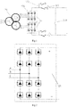
- each sub-converter 121 all use a three-phase bridge-type six-pulse rectification structure, and each sub-converter 121 includes an A-phase module, a B-phase module and a C-phase module connected in parallel.
- Each phase module includes a first diode valve string and a second diode valve string connected in series, and a common connecting end of the first diode valve strings and a common connecting end of the second diode valve strings are configured for connection with an external alternating current power supply.
- the first diode valve string and the second diode valve string both include a plurality of diode valves connected in parallel and/or in series. The number and connection relationship of the diode valves depend on voltage and current (the number of the diode valves connected in series depends on existing voltage and the number of the diode valves connected in parallel depends on existing current).
- all the diode valves in each phase module are of the same structure, which specifically includes a first capacitor, a first resistor, a second resistor and a first diode.
- the first capacitor is connected in series with the first resistor and then connected in parallel with the first diode, the first capacitor is connected with a negative pole of the first diode, and the second resistor is connected in parallel with the first diode.
- outputs of the plurality of sub-converters 121 are connected with a sub-smoothing reactor (not shown in the drawings) and a sub-bypass switch (not shown in the drawings), the sub-bypass switch may bypass the failed sub-converter 121, or the sub-smoothing reactor or the sub-bypass switch may be used separately.
- an alternating current filter 130 is provided at an input of the rectifier transformer 110 as shown in FIG. 3 , and the alternating current filter 130 and the converter 120 are arranged on a same supporting platform.
- outputs of the converter 120 are connected in parallel with the bypass switch 140 which, in the case of a failure, is turned off, thus realizing bypass communication of a failed circuit, and playing a better role in maintenance and troubleshooting together with the function selection switch 123.
- the bypass switch 140 and the rectifier transformer 110 are arranged on the same supporting platform.
- a filter unit (not shown in the drawings) may be arranged at the input of the converter 120 to achieve a better filtering effect.
- volume of the whole converter station 100 can be further reduced.
- the converter station 100 is integrally installed on one supporting platform and is able to be installed on an offshore supporting platform, thus further reducing difficulty in offshore remote power transmission.
- a power transmission system includes an onshore convertor platform 200 and the above converter station 100.
- An input of the converter station 100 is connected with an external power supply device, and an output of the converter station is connected with an input of the onshore convertor platform 200.
- An output of the onshore convertor platform 200 is connected with an external alternating current power grid, and the onshore convertor platform 200 is configured for converting a direct current into an alternating current.
- a plurality of converter stations 100 are provided. Outputs of the plurality of converter stations are sequentially connected in series and then connected with the onshore convertor platform 200.
- three converter stations 100 are used and arranged on offshore platforms A, B and C respectively.
- the onshore convertor platform 200 includes a convertor station 210 and an onshore transformer 220.
- An input of the convertor station 210 is connected with the output of the converter station 100, and an output of the convertor station is connected with an input of the onshore transformer 220.
- An output of the onshore transformer 220 is configured for connection with the external alternating current power grid.
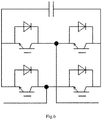
- the convertor station 210 uses a MMC (modular-multilevel-converter) structure, and the convertor station 210 includes six bridge arms, which all include a plurality of power modules sequentially connected in series, and the plurality of power modules are all configured for converting the direct current to the alternating current. All of the plurality of power modules are of a half-bridge structure and/or a full-bridge structure as shown in FIG. 5 and FIG. 6 .
- MMC module-multilevel-converter
- the six bridge arms of the convertor station 210 are all connected with a CT transformer, a bridge-arm smoothing reactor 211 or a series structure of the CT transformer and the bridge-arm smoothing reactor 211.
- the series structure of the CT transformer and the bridge-arm smoothing reactor 211 is preferably used in the embodiment.
- the above power transmission system is further provided with an alternating current auxiliary power supply system 300.
- An input of the alternating current auxiliary power supply system 300 is connected with the output of the onshore convertor platform 200 or an external power supply, and an output of the alternating current auxiliary power supply system is connected with the input of the converter station 100 by a power distribution device.
- the alternating current auxiliary power supply system 300 is configured for auxiliary power supply to the external power generation field.
- the alternating current auxiliary power supply system 300 is connected with the input of the converter station 100 through a power distribution device.
- a power distribution cabinet may be used.
- the alternating current auxiliary power supply system 300 includes an offshore alternating current cable and an onshore auxiliary power supply device.
- the auxiliary power supply device include a first alternating current circuit breaker, a transformer and a second alternating current circuit breaker which are sequentially connected in series, and the transformer is configured for voltage regulation.
- the transformer may use a regulating transformer, a power electronic converter or a series structure of the regulating transformer and the power electronic converter.
- the series structure of the regulating transformer and the power electronic converter is specifically used to realize a voltage regulation function.
- the onshore convertor platform 200 and the converter station 100 are connected by a high-voltage submarine cable, thus having better stability and safety.
- a plurality of onshore transformers 220 are provided, inputs of the plurality of onshore transformers 220 connected in parallel are connected with the outputs of the convertor stations 210, and outputs of the plurality of onshore transformers are connected with the external alternating current power grid.
- two onshore transformers 220 are connected in parallel, thus improving a stability of the whole system well.
Landscapes
- Engineering & Computer Science (AREA)
- Power Engineering (AREA)
- Rectifiers (AREA)
Applications Claiming Priority (2)
| Application Number | Priority Date | Filing Date | Title |
|---|---|---|---|
| CN201910846958.5A CN110556864A (zh) | 2019-09-09 | 2019-09-09 | 一种远程输电变流站及输电系统 |
| PCT/CN2019/120233 WO2021047058A1 (fr) | 2019-09-09 | 2019-11-22 | Station de conversion de transmission d'énergie à distance et système de transmission d'énergie |
Publications (2)
| Publication Number | Publication Date |
|---|---|
| EP3820013A1 true EP3820013A1 (fr) | 2021-05-12 |
| EP3820013A4 EP3820013A4 (fr) | 2022-06-22 |
Family
ID=68739460
Family Applications (1)
| Application Number | Title | Priority Date | Filing Date |
|---|---|---|---|
| EP19929190.7A Pending EP3820013A4 (fr) | 2019-09-09 | 2019-11-22 | Station de conversion de transmission d'énergie à distance et système de transmission d'énergie |
Country Status (3)
| Country | Link |
|---|---|
| EP (1) | EP3820013A4 (fr) |
| CN (1) | CN110556864A (fr) |
| WO (1) | WO2021047058A1 (fr) |
Cited By (3)
| Publication number | Priority date | Publication date | Assignee | Title |
|---|---|---|---|---|
| CN113258598A (zh) * | 2021-06-01 | 2021-08-13 | 南方电网科学研究院有限责任公司 | 一种海上风电直流送出的拓扑电路及控制方法 |
| CN113452061A (zh) * | 2021-07-05 | 2021-09-28 | 南方电网科学研究院有限责任公司 | 一种海上风电直流输电系统及其控制方法 |
| US20220252046A1 (en) * | 2019-10-30 | 2022-08-11 | Zhejiang University | High-frequency uncontrolled rectifier-based dc transmission system for offshore wind farm |
Families Citing this family (3)
| Publication number | Priority date | Publication date | Assignee | Title |
|---|---|---|---|---|
| CN111416386A (zh) * | 2020-04-01 | 2020-07-14 | 广东安朴电力技术有限公司 | 一种输电系统及其供电装置 |
| CN112072686A (zh) * | 2020-08-03 | 2020-12-11 | 中国南方电网有限责任公司超高压输电公司检修试验中心 | 一种海上风电升压站与柔直换流阀组合建换流站及系统 |
| CN113472001A (zh) * | 2021-08-16 | 2021-10-01 | 南方电网科学研究院有限责任公司 | 海上风电送端混合双极的直流输电系统及控制方法、设备 |
Family Cites Families (12)
| Publication number | Priority date | Publication date | Assignee | Title |
|---|---|---|---|---|
| DK2096732T3 (da) * | 2008-02-27 | 2011-01-03 | Abb Schweiz Ag | Energisystem, som omfatter en vind- eller vandkraftturbine |
| CN101976956A (zh) * | 2010-08-26 | 2011-02-16 | 梁一桥 | 一种单向功率传送的低成本直流输电系统 |
| EP3109464B1 (fr) * | 2013-02-28 | 2019-08-21 | Siemens Aktiengesellschaft | Liaison de parc eolien comprenant un redresseur a diodes |
| CN203632052U (zh) * | 2013-12-30 | 2014-06-04 | 卧龙电气集团股份有限公司 | 一种矿山用预装式牵引整流变电站 |
| WO2015149870A1 (fr) * | 2014-04-04 | 2015-10-08 | Siemens Aktiengesellschaft | Circuit de commutation |
| CN204144040U (zh) * | 2014-07-17 | 2015-02-04 | 中电电气(江苏)股份有限公司 | 36脉波移相整流变压器 |
| CN204206057U (zh) * | 2014-11-14 | 2015-03-11 | 中国海洋石油总公司 | 海上平台采油电潜泵变频驱动系统 |
| CN106099968A (zh) * | 2016-08-05 | 2016-11-09 | 西安许继电力电子技术有限公司 | 海上风电场直流输电系统直流短路故障穿越方法和系统 |
| US11011894B2 (en) * | 2017-05-24 | 2021-05-18 | J. Ray Mcdermott, S.A. | HVDC modular platform design |
| CN108111030B (zh) * | 2017-12-07 | 2020-09-15 | 上海交通大学 | 混合型海上风场直流换流器 |
| CN107947243A (zh) * | 2018-01-08 | 2018-04-20 | 清华大学 | 一种分布式海上平台串联的海上风电直流输电系统 |
| CN210693470U (zh) * | 2019-09-09 | 2020-06-05 | 广东安朴电力技术有限公司 | 一种变流站及输电系统 |
-
2019
- 2019-09-09 CN CN201910846958.5A patent/CN110556864A/zh active Pending
- 2019-11-22 WO PCT/CN2019/120233 patent/WO2021047058A1/fr unknown
- 2019-11-22 EP EP19929190.7A patent/EP3820013A4/fr active Pending
Cited By (4)
| Publication number | Priority date | Publication date | Assignee | Title |
|---|---|---|---|---|
| US20220252046A1 (en) * | 2019-10-30 | 2022-08-11 | Zhejiang University | High-frequency uncontrolled rectifier-based dc transmission system for offshore wind farm |
| US11791632B2 (en) * | 2019-10-30 | 2023-10-17 | Zhejiang University | High-frequency uncontrolled rectifier-based DC transmission system for offshore wind farm |
| CN113258598A (zh) * | 2021-06-01 | 2021-08-13 | 南方电网科学研究院有限责任公司 | 一种海上风电直流送出的拓扑电路及控制方法 |
| CN113452061A (zh) * | 2021-07-05 | 2021-09-28 | 南方电网科学研究院有限责任公司 | 一种海上风电直流输电系统及其控制方法 |
Also Published As
| Publication number | Publication date |
|---|---|
| CN110556864A (zh) | 2019-12-10 |
| EP3820013A4 (fr) | 2022-06-22 |
| WO2021047058A1 (fr) | 2021-03-18 |
Similar Documents
| Publication | Publication Date | Title |
|---|---|---|
| EP3820013A1 (fr) | Station de conversion de transmission d'énergie à distance et système de transmission d'énergie | |
| Westman et al. | Valhall re-development project, power from shore | |
| CN101741094B (zh) | 一种基于可关断器件的移动式输电装置 | |
| CN103607032B (zh) | 可再生能源发电、输变电和电网接入一体化系统 | |
| US8866338B2 (en) | Method and apparatus for improving power generation in a thermal power plant | |
| CN102025155A (zh) | 基于直流配电的微网系统 | |
| CN105356757A (zh) | 一种单向直流-直流自耦变压器 | |
| CN104485821A (zh) | 配电用直流变压器装置 | |
| CN102142688B (zh) | 电能并网系统以及电能传输系统和方法 | |
| CN110729909B (zh) | 一种多端口铁路功率调节器系统及其综合控制方法 | |
| CN104218573A (zh) | 一种受端电网发生故障时mmc-hvdc的控制方法 | |
| CN209217732U (zh) | 交直流混合微电网储能系统 | |
| CN102611144A (zh) | 基于多重化技术的光伏并网发电装置 | |
| JP6454540B2 (ja) | 電力変換装置 | |
| CN105391079A (zh) | 一种基于新能源互连的功率融通型平衡供电系统及方法 | |
| CN210693470U (zh) | 一种变流站及输电系统 | |
| CN115207959B (zh) | 一种基于lcc和全桥mmc-statcom混合串联的海上风电直流输电系统 | |
| CN102946102B (zh) | 潮流发电机组变流输电系统的工作方法 | |
| CN105785176B (zh) | 一种多规格全功率风电变流器测试平台 | |
| CN205004960U (zh) | 直流dc到交流ac的变换器 | |
| CN213937744U (zh) | 一种基于集电器的海上风电直流汇集组网结构 | |
| CN109617120B (zh) | 直流风力发电机组及风电场 | |
| CN106564397A (zh) | 直流充电的充电站系统 | |
| Dias et al. | Power electronics in the context of renewables, power quality and smart grids | |
| CN110932316A (zh) | 一种海上风力与波浪联合发电机组 |
Legal Events
| Date | Code | Title | Description |
|---|---|---|---|
| STAA | Information on the status of an ep patent application or granted ep patent |
Free format text: STATUS: UNKNOWN |
|
| STAA | Information on the status of an ep patent application or granted ep patent |
Free format text: STATUS: THE INTERNATIONAL PUBLICATION HAS BEEN MADE |
|
| PUAI | Public reference made under article 153(3) epc to a published international application that has entered the european phase |
Free format text: ORIGINAL CODE: 0009012 |
|
| STAA | Information on the status of an ep patent application or granted ep patent |
Free format text: STATUS: REQUEST FOR EXAMINATION WAS MADE |
|
| 17P | Request for examination filed |
Effective date: 20201126 |
|
| AK | Designated contracting states |
Kind code of ref document: A1 Designated state(s): AL AT BE BG CH CY CZ DE DK EE ES FI FR GB GR HR HU IE IS IT LI LT LU LV MC MK MT NL NO PL PT RO RS SE SI SK SM TR |
|
| RIC1 | Information provided on ipc code assigned before grant |
Ipc: H02M 7/5387 20070101ALI20220228BHEP Ipc: H02M 7/537 20060101ALI20220228BHEP Ipc: H02J 3/36 20060101ALI20220228BHEP Ipc: H02J 3/38 20060101AFI20220228BHEP |
|
| REG | Reference to a national code |
Ref country code: DE Ref legal event code: R079 Free format text: PREVIOUS MAIN CLASS: H02J0003380000 Ipc: H02M0005458000 |
|
| A4 | Supplementary search report drawn up and despatched |
Effective date: 20220525 |
|
| RIC1 | Information provided on ipc code assigned before grant |
Ipc: H02J 3/38 20060101ALI20220519BHEP Ipc: H02M 7/483 20070101ALI20220519BHEP Ipc: H02M 7/757 20060101ALI20220519BHEP Ipc: H02M 5/458 20060101AFI20220519BHEP |
|
| DAV | Request for validation of the european patent (deleted) | ||
| DAX | Request for extension of the european patent (deleted) | ||
| STAA | Information on the status of an ep patent application or granted ep patent |
Free format text: STATUS: EXAMINATION IS IN PROGRESS |
|
| 17Q | First examination report despatched |
Effective date: 20230822 |