EP3820006B1 - Verfahren zum entfernen einer kabelfolie - Google Patents
Verfahren zum entfernen einer kabelfolie Download PDFInfo
- Publication number
- EP3820006B1 EP3820006B1 EP19207945.7A EP19207945A EP3820006B1 EP 3820006 B1 EP3820006 B1 EP 3820006B1 EP 19207945 A EP19207945 A EP 19207945A EP 3820006 B1 EP3820006 B1 EP 3820006B1
- Authority
- EP
- European Patent Office
- Prior art keywords
- cable
- section
- foil
- film
- conductor structure
- Prior art date
- Legal status (The legal status is an assumption and is not a legal conclusion. Google has not performed a legal analysis and makes no representation as to the accuracy of the status listed.)
- Active
Links
Images


Classifications
-
- H—ELECTRICITY
- H02—GENERATION; CONVERSION OR DISTRIBUTION OF ELECTRIC POWER
- H02G—INSTALLATION OF ELECTRIC CABLES OR LINES, OR OF COMBINED OPTICAL AND ELECTRIC CABLES OR LINES
- H02G1/00—Methods or apparatus specially adapted for installing, maintaining, repairing or dismantling electric cables or lines
- H02G1/12—Methods or apparatus specially adapted for installing, maintaining, repairing or dismantling electric cables or lines for removing insulation or armouring from cables, e.g. from the end thereof
- H02G1/1275—Methods or apparatus specially adapted for installing, maintaining, repairing or dismantling electric cables or lines for removing insulation or armouring from cables, e.g. from the end thereof by applying heat
- H02G1/128—Methods or apparatus specially adapted for installing, maintaining, repairing or dismantling electric cables or lines for removing insulation or armouring from cables, e.g. from the end thereof by applying heat using radiant energy, e.g. a laser beam
-
- H—ELECTRICITY
- H01—ELECTRIC ELEMENTS
- H01R—ELECTRICALLY-CONDUCTIVE CONNECTIONS; STRUCTURAL ASSOCIATIONS OF A PLURALITY OF MUTUALLY-INSULATED ELECTRICAL CONNECTING ELEMENTS; COUPLING DEVICES; CURRENT COLLECTORS
- H01R43/00—Apparatus or processes specially adapted for manufacturing, assembling, maintaining, or repairing of line connectors or current collectors or for joining electric conductors
- H01R43/28—Apparatus or processes specially adapted for manufacturing, assembling, maintaining, or repairing of line connectors or current collectors or for joining electric conductors for wire processing before connecting to contact members, not provided for in groups H01R43/02 - H01R43/26
-
- H—ELECTRICITY
- H02—GENERATION; CONVERSION OR DISTRIBUTION OF ELECTRIC POWER
- H02G—INSTALLATION OF ELECTRIC CABLES OR LINES, OR OF COMBINED OPTICAL AND ELECTRIC CABLES OR LINES
- H02G1/00—Methods or apparatus specially adapted for installing, maintaining, repairing or dismantling electric cables or lines
- H02G1/12—Methods or apparatus specially adapted for installing, maintaining, repairing or dismantling electric cables or lines for removing insulation or armouring from cables, e.g. from the end thereof
- H02G1/1202—Methods or apparatus specially adapted for installing, maintaining, repairing or dismantling electric cables or lines for removing insulation or armouring from cables, e.g. from the end thereof by cutting and withdrawing insulation
- H02G1/1248—Machines
-
- H—ELECTRICITY
- H02—GENERATION; CONVERSION OR DISTRIBUTION OF ELECTRIC POWER
- H02G—INSTALLATION OF ELECTRIC CABLES OR LINES, OR OF COMBINED OPTICAL AND ELECTRIC CABLES OR LINES
- H02G1/00—Methods or apparatus specially adapted for installing, maintaining, repairing or dismantling electric cables or lines
- H02G1/12—Methods or apparatus specially adapted for installing, maintaining, repairing or dismantling electric cables or lines for removing insulation or armouring from cables, e.g. from the end thereof
- H02G1/1275—Methods or apparatus specially adapted for installing, maintaining, repairing or dismantling electric cables or lines for removing insulation or armouring from cables, e.g. from the end thereof by applying heat
- H02G1/1282—Methods or apparatus specially adapted for installing, maintaining, repairing or dismantling electric cables or lines for removing insulation or armouring from cables, e.g. from the end thereof by applying heat removing metallic shields
-
- H—ELECTRICITY
- H02—GENERATION; CONVERSION OR DISTRIBUTION OF ELECTRIC POWER
- H02G—INSTALLATION OF ELECTRIC CABLES OR LINES, OR OF COMBINED OPTICAL AND ELECTRIC CABLES OR LINES
- H02G1/00—Methods or apparatus specially adapted for installing, maintaining, repairing or dismantling electric cables or lines
- H02G1/12—Methods or apparatus specially adapted for installing, maintaining, repairing or dismantling electric cables or lines for removing insulation or armouring from cables, e.g. from the end thereof
- H02G1/1297—Removing armouring from cables
-
- H—ELECTRICITY
- H02—GENERATION; CONVERSION OR DISTRIBUTION OF ELECTRIC POWER
- H02G—INSTALLATION OF ELECTRIC CABLES OR LINES, OR OF COMBINED OPTICAL AND ELECTRIC CABLES OR LINES
- H02G1/00—Methods or apparatus specially adapted for installing, maintaining, repairing or dismantling electric cables or lines
- H02G1/12—Methods or apparatus specially adapted for installing, maintaining, repairing or dismantling electric cables or lines for removing insulation or armouring from cables, e.g. from the end thereof
- H02G1/1202—Methods or apparatus specially adapted for installing, maintaining, repairing or dismantling electric cables or lines for removing insulation or armouring from cables, e.g. from the end thereof by cutting and withdrawing insulation
- H02G1/1248—Machines
- H02G1/1251—Machines the cutting element not rotating about the wire or cable
- H02G1/1253—Machines the cutting element not rotating about the wire or cable making a transverse cut
- H02G1/1256—Machines the cutting element not rotating about the wire or cable making a transverse cut using wire or cable-clamping means
Definitions
- the invention relates to a method for removing a section of a cable foil from an end section of a cable, the cable comprising a cable jacket and at least one electrically conductive conductor structure and the cable foil made of a plastic applied to one of the conductor structures, and a processing device for carrying out the method.
- electrically conductive conductor structure or conductor structure is understood to mean a preferably metallic structure which is suitable for conducting electric current and in which circular currents or eddy currents can be induced by means of an electromagnetic field.
- conductor structure includes both inner conductors, such as solid conductors or stranded conductors, and outer conductor structures, such as conductor braids or electrically conductive foils, preferably metal foils.
- cables particularly if they comprise an inner conductor as the inner conductor structure and one or more outer conductor structures, include one or more further insulation layers, the outer insulation layer being referred to as the cable sheath.
- a cable film made of plastic can be arranged between one of the conductor structures and the insulating layer above it, which can serve for mechanical protection, for electromagnetic shielding or for protection against moisture.
- the cable foil can be arranged between the braided shield and the cable sheath in order to allow the cable sheath to be pulled off, since the cable sheath would get caught with the underlying braided shield without the cable foil.
- end section of a cable is understood to mean that area of a cable which extends from one end along a cable axis at least over that area in which the conductor structures for contacting are or are to be exposed.
- the end section also includes a section adjoining the stripped section of the cable, in which section the cable jacket is intact and is preferably between 1 cm and 25 cm, particularly preferably between 5 cm and 15 cm, long.
- the section of the cable foil to be removed usually extends over part of the end section of the cable, preferably starting at the cable end of the end section.
- the EP 3 444 911 A1 discloses a method for removing a cable foil, in which first a section of the cable foil to be processed is exposed and this exposed section is then subjected to a thermal, abrasive or chemical treatment in the area of an intended crack position. A heated mold or a heating wire is mentioned for the thermal treatment, by means of which the cable foil can be melted on or off.
- the JP 2018 207624 A discloses a device by means of which a section of a cable sheath of a cable is exposed by a corresponding separating device and then a burning device comprising a heating element and an energy supply device is brought up to the exposed cable foil in order to burn off this and any remaining residue of the cable sheath.
- the DE 10 2017 221115 B3 shows a device by means of which an end section of a cable sheath of a cable is softened by inductive heating in order to mechanically remove the section using a stripping tool.
- the CN 207 765 892 U discloses an apparatus for stripping a cable in which the cable is passed through a heating coil to soften the cable jacket therein and thereby protect the cutting edges of the stripping knives and reduce their wear.
- a disadvantage of the prior art is that in order to remove the section of the cable foil that is to be removed, the cable sheath must be partially removed.
- the proposed method requires a complicated device which requires either a rotation of the cable for uniform heating or a heatable mold specially adapted to the cable to be processed.
- a further object is to enable the cable foil to be removed in sections without the cable foil having to be exposed before the treatment.
- the solution according to the invention is characterized in that the targeted damage to the cable foil in a defined damage area does not take place through direct heat application, but that the conductor structure lying below the cable foil—in relation to the cable axis—is heated inductively and thus without contact.
- the inductive heat input makes it possible to generate the heat directly in the area in which it is needed to pre-damage the cable foil. Other areas of the cable, in particular the cable sheath, are not heated, or at least not significantly so. Furthermore, the heat input is completely contact-free, so that it is not necessary to remove the cable sheath in the damaged area before the heat treatment.
- the non-contact heating means that there is no mechanical damage to the lower layer or layers when the cable foil is removed.
- the inductive heating can also be used on a cable foil that has already been exposed, even if this is not intended according to the invention.
- a further advantage of the method according to the invention is that the cable foil can be heated in a precisely defined damage area by the inductive heating in a simple manner, with the damage area of the cable foil - without further manipulation of the cable being necessary - based on a Cross-section of the cable preferably over the entire circumference extends.
- the inductive heating by means of which the conductor structure can be heated up essentially uniformly in a defined area, makes it possible for the cable foil to be thermally damaged over its entirety.
- the induction parameters such as heating power and holding time, can be selected accordingly in order to set the penetration depth and the temperature.
- Other parameters that can be used to influence the induction parameters are the frequency and amplitude of the alternating current flowing through the inductor and the geometric design of the inductor.
- the damage area can be defined particularly precisely by setting that area in which the maximum temperature is reached.
- Targeted thermal damage to the cable foil in the damage area determines the position of the cable in which the cable foil and/or the underlying conductor structure, if this is also to be removed, tears when pulled off.
- the relative movement of the cable foil in relation to one of the conductor structures, preferably in relation to the conductor structure to be exposed, can be accomplished by pulling off the cable foil. When it is pulled off, the cable foil is moved directly or with an additional layer in between in the direction of the cable axis, i.e. in the direction of an end face of the end section, also called the cable end.
- the relative movement is a torsional movement or a buckling movement, as a result of which the crack forms.
- the section to be removed defined by the crack can be removed from the cable, preferably by pulling it off.
- steps of inductive heating and relative movement it is not absolutely necessary for the steps of inductive heating and relative movement to take place immediately one after the other in the same processing space, since these steps can also take place in different processing spaces, such as inductive heating in a processing space of one Induction unit and the relative movement in a further processing room of a dismantling device, can be performed spatially separated from each other.
- thermally damaged means both melting, melting or plasticizing of the cable foil and burning, burning, embrittlement or degradation of the cable foil, with the type of thermal damage essentially depending on the material of the cable foil and the duration and the level of heat input. If the cable foil in the damaged area has melted, partially melted, become brittle or solidified again after the inductive heat treatment, the tear forms in the cable foil during the relative movement or when it is pulled off. If the cable foil is burnt or burnt off as a result of the heating, the tear is already present before it is pulled off and is only enlarged by the pulling off.
- a conductor structure designed as an inner conductor is heated by the inductive heating in order to at least partially melt a cable foil applied to the inner conductor in the damaged area in order to be able to remove the cable foil from the inner conductor.
- the inductive heating of that conductor structure to which the cable film is applied can also take place when the cable comprises two or more conductor structures. This can also result in inductive heating of those conductor structures to which no cable foil is applied. Due to the small thickness of the cable foil, however, there is defined damage in the area of the cable foil, while other layers are usually not significantly affected. Furthermore, the heating of those conductor structures on which no cable foil is applied can be reduced by suitably selecting the induction parameters, with the skin effect being able to be used in particular at high frequencies.
- the cable has a cable axis which, based on a cross section of the cable, represents the axis of symmetry. It goes without saying that the cable axis is normal to the corresponding cross section of the cable and can also run in a curve if the cable is bent. As a rule, the end section of the cable is not bent, so that the cable axis runs in a straight line in the end section.
- the at least one conductor structure is composed of an inner conductor and at least one outer conductor structure, with the cable foil being applied to one of the outer conductor structures.
- the cable foil is preferably applied to the outermost conductor structure in relation to the cable axis if more than one outer conductor structure is provided.
- the cable foil it is also conceivable for the cable foil to be applied to an outer conductor structure located further inwards or to the inner conductor.
- a cable foil is applied to several of the conductor structures. In all of the aforementioned cases, it is advantageous if the machining takes place from the outside inwards, with the different machining sections usually being offset in stages. It goes without saying that the cable film is applied to the outer conductor structure if only one outer conductor structure is present.
- the at least one outer conductor structure can comprise a metal braid, such as a braided shield, and/or a metal foil, in particular consist of a braided shield and/or a metal foil.
- the cable foil could be attached to the metal mesh, in particular to the Shielding braid is applied or the shielding braid is wrapped and inductively heated by the shielding braid, so that the cable film is at least partially thermally damaged.
- a preferred embodiment variant of the method according to the invention provides that the outer conductor structure to which the cable foil is applied is designed as a metal foil. Due to the relatively small thickness of the metal foil, it can be heated particularly efficiently by appropriate adjustment of the penetration depth of the inductive heating.
- the metal foil is preferably an aluminum-containing foil or an aluminum foil. Due to the fact that the metal foil has a small thickness and therefore usually has a low tensile or shear resistance and that the cable foil is thermally damaged in the damaged area, so that the cable foil in the damaged area no longer has any significant increasing influence on tensile and shear resistance the tear in the cable foil during the relative movement also leads to the formation of tears or damage to the metal foil in the damaged area.
- the at least one outer conductor structure comprises a braided shield and a metal foil, with the metal foil being arranged directly on the braided shield.
- the cable foil is applied directly to the metal foil.
- the inductive heating can lead to a cumulative heating effect of the braided shield and the metal foil, but the heating that can be achieved in the outer conductor structure is usually in relation to the possible penetration depth, so that the metal foil is heated more than the braided shield due to its lower thickness.
- the metal foil and the cable foil are designed as a composite foil.
- the outer conductor structure which is designed as a metal foil, is structurally weakened by the inductive heating in the damaged area. If the outer conductor structure on which the cable foil is applied is in the form of a metal foil, it is advantageous if the metal foil is pulled off together with the cable foil. Accordingly, an expansion of the damaged area from the cable foil to the metal foil due to the structural weakening of the metal foil means that a defined tear also forms in the metal foil when it is pulled off in the damaged area, so that the metal foil and cable foil can be pulled off together without residues on the one below Layer remain, which would be a hindrance to any contacting.
- At least the corresponding conductor structure can be inductively heated particularly easily if the inductive heating takes place by means of an induction coil, by means of which induction coil an alternating electromagnetic field is generated, with at least the damaged area of the cable being arranged within the induction coil during the inductive heating.
- an induction coil By generating an alternating electromagnetic field in a preferably water-cooled induction coil, the frequency and amplitude of the alternating current flowing through the induction coil can be regarded as relevant parameters for the inductive heating.
- the use of an induction coil also makes it particularly easy to ensure that the cable foil is completely damaged, since at least one area of the end section of the cable is arranged in the induction coil during heating and the corresponding conductor structure is correspondingly heated uniformly over the entire circumference.
- inductive heating can be used for a large number of different cable diameters or cable types, as long as a required distance between the inside diameter of the induction coil and the outside diameter of the cable section accommodated is maintained.
- which distance can be formed, for example, as an air gap or can be filled by a non-conductive material.
- the inductive heating can also be used on a cable foil that has already been exposed, it is advantageous if the heat treatment can be carried out without the cable sheath having to be removed in the damaged area. Accordingly, it is further provided according to the invention that the cable foil is covered by the cable sheath in the damaged area during the inductive heating of the at least one conductor structure. In other words, the cable sheath is intact in the damaged area or in the section of the cable that is inserted into the induction coil, so that the cable foil is heated inside the cable. This is only possible thanks to the inductive heating of the conductor structure underneath the cable foil, since the required heating does not take place from the outside with the inductive heating, but directly where the heat is needed. In other words, the conductor structure on which the cable foil is applied is inductively heated through the cable sheath in order to produce the damaged area.
- the cable comprises three conductor structures, namely an inner conductor, a braided shield and a metal foil, with the braided shield, metal foil and cable foil being arranged directly one above the other in this order, i.e. it is a coaxial cable.
- the braided shield, metal foil and cable foil being arranged directly one above the other in this order, i.e. it is a coaxial cable.
- the cutting takes place before the inductive heating of the damaged area, possibly even before the end section is introduced into the processing space of a processing device, as it is conceivable that the cutting takes place during or after the inductive heat treatment of the damaged area . For example, cutting into a further processing space of a cutting device. Finally, the removal of the cable jacket is not a necessary step for performing the heat treatment.
- the distance between the position of the incision and the end of the cable is less than the distance between the damaged area and the end of the cable
- the Damage area is arranged in a non-claimed embodiment closer or equally close to the end of the cable than the incision, so that a section of the cable film may be exposed after the cable sheath has been pulled off.
- the cable foil can be removed particularly easily in that it is pulled off the end section of the cable together with the cable sheath immediately above it, since the cable foil usually has increased adhesion to the cable sheath. If the cable sheath is cut, preferably as described above, the cable sheath can be moved relative to one of the conductor structures, in particular relative to the inner conductor, using appropriate means, with the cable foil underneath or the cable foil underneath and/or the cable underneath the Tear the metal foil lying on the cable foil in the damaged area and can be pulled off together with the cable sheath.
- the relative movement can in turn be a buckling movement, a rotary movement and/or a pulling movement, ie a movement in the direction of the cable axis towards the cable end of the end section.
- a further embodiment of the invention provides that the cable jacket is divided by an at least partially circumferential, preferably completely circumferential, incision into a section of the cable jacket to be removed and a remaining section of the cable jacket and that the section of the cable sheath to be removed is moved in the direction of the cable axis, wherein the section of the cable foil to be removed which is at least partially adhering to the cable sheath is pulled off by the movement.
- the cable foil has proven to be particularly advantageous for the cable foil to be heated to a temperature in a preferred temperature range, which temperature can be set by the temperature of the underlying inductively heated conductor structure. It is therefore provided in a further embodiment variant that the at least one conductor structure is inductively heated to a temperature of greater than or equal to 80°C, preferably greater than or equal to 100°C, particularly preferably greater than or equal to 200°C, in particular greater than or equal to 300°C.
- the temperature can be measured, for example, by means of a pyrometer.
- the temperature of the inductively heated conductor structure and the duration of the inductive heating for example less than 30 s, in particular less than 20 s, preferably less than 10 s, can depend on the material properties of the cable foil, for example the thickness and/or the type of plastic, can be adjusted in order to achieve the thermal damage.
- the combination of inductive heat treatment and removal of the cable foil in a processing device reduces the number of necessary manipulation processes and enables efficient removal of the cable foil. It is only necessary for a processing operation to introduce the section of the cable to be processed into the induction coil. However, it is conceivable that the section of the cable foil to be removed is not completely but only partially pulled off by the means provided.
- the means for pulling off the section of the cable foil to be removed can, for example, be translational moveable gripping and/or moving elements act, which grasp the cable foil directly and can move and/or twist relative to a layer underneath the cable foil, for example to an inner conductor or a braided shield. It is conceivable that several movements can be carried out one after the other by the means for pulling off, for example a twisting or buckling movement to produce a tear in the damaged area of the cable foil and a subsequent linear pulling movement to remove the section of the cable foil to be removed, possibly together with a section of cable jacket to be removed. It is also conceivable that the means for pulling off are designed as a correspondingly designed cable film removal device.
- the means for removing the cable foil can make direct contact with the cable foil.
- the means for pulling off the cable foil can be formed by a cutting unit for making an incision in the cable sheath, which can also perform a relative movement in the direction of the cable axis after the incision.
- the means for pulling off the cable foil can be a device which is designed in such a way that at least the section of the cable foil to be removed, preferably together with a section of the cable sheath to be removed, relative to one of the conductor structures, preferably relative to a metal mesh or the inner conductor, so that a crack forms at least in the cable foil in the damaged area.
- the means for pulling off a section of the cable foil do not necessarily have to be arranged in the processing space in which the induction coil is also arranged, particularly if the processing device is designed as a system with several sub-devices. That's how it is conceivable that the means for pulling off a section of the cable foil are arranged, for example, in a further processing space of a stripping device of the processing device, preferably the system.
- such a device can be used to treat both end sections of a cable in which the cable film has already been exposed by removing the cable sheath and end sections of cables with an intact cable sheath can be processed, provided that either a cutting unit is provided or the cable sheath before it is inserted into the processing device has already been cut.
- an induction coil which is set up to inductively heat a conductor structure, so that the cable film applied to the heated conductor structure is at least partially thermally damaged in a damage area
- Conductor structure applied non-metallic intermediate layer can be fabric structures preferably impregnated with resin, for example made of materials such as cotton or paper.
- Such non-metallic interlayers are typically designed to protect an underlying metal foil outer conductor structure from tearing.
- a correspondingly designed induction coil can also be suitable for thermally damaging an adhesive layer applied to the heated conductor structure.
- At least one clamping unit for fixing the end section of the cable during the machining process is arranged in the machining area.
- the at least one clamping unit preferably includes at least one clamping element, which is preferably made of plastic is to be able to be positioned in the vicinity of the induction coil.
- the end section of the cable can be efficiently fixed by means of the clamping unit in order to enable both the inductive heat treatment and the relative movement of the cable foil relative to one of the conductor structures, preferably relative to an inner conductor, without the cable moving relative to the processing space.
- the processing device further comprises a cutting unit for at least partially circumferential cutting of the cable sheath. Since the cable sheath does not have to be exposed in the damaged area in order to carry out the inductive heating of the at least one conductor structure, the cable sheath can be cut into and, if necessary, subsequently removed directly in the processing device, in particular if the means for stripping include the cutting unit.
- the cutting unit can, for example, have at least one cutting element, preferably at least two, exactly two or more than two, cutting elements which penetrate into the cable sheath in the radial direction during the cutting movement in order to produce an at least partially, preferably completely, circumferential incision.
- the claimed embodiment of the processing device provides that the cutting unit is arranged in the processing space, the processing space having a passage opening for the cable and the induction coil being arranged between the cutting unit and passage opening.
- the cutting unit is arranged between the stripping means and the induction coil.
- a corresponding arrangement of the cutting unit in the processing area, in which the induction coil is also arranged, ensures that the partially circumferential incision in the cable sheath takes place at a position which is arranged closer to a cable end of the cable than that caused by the inductive heating of the corresponding conductor structure generated damage area. Since the end section of the cable usually only makes up a small section of the total length of the cable, a passage opening for the cable is usually provided in the processing room, through which the section of the cable to be processed can be introduced into the processing room or through which the section cannot be inserted to be processed section of the cable can be performed from the processing room.
- the induction coil which produces the damage area, is between the cutting unit and the passage opening arranged.
- a further embodiment variant of the invention provides that the means for peeling off the section of the cable foil to be removed are designed to contact a section of the cable jacket to be removed defined by an incision and subsequently the section of the cable jacket to be removed together with a section of the cable foil to be removed, which preferably adheres to the cable jacket, be removed with a peeling motion.
- the incision in the cable sheath can either be made with the previously mentioned cutting unit or the incision can already be present in the inserted end section of the cable.
- the means for removing the end section of the cable foil can in turn be designed as gripping elements or sliding elements, which, however, do not have to contact and grasp the thin cable foil, but rather the thicker cable sheath.
- gripping and relative movement for example pushing, pulling, twisting or kinking, the section of the cable sheath to be removed relative to one of the conductor structures, preferably relative to the inner conductor, the cable foil underneath and at least partially adhering to the cable sheath is also stretched so that the cable foil in the Damage area tears and can then be pulled off.
- the pull-off movement which includes a movement of the section of the cable sheath to be removed in the direction of the cable end, can either be used at the same time to generate cracks or only after the crack has been generated, by means of a relative movement carried out beforehand.
- the inductively heated conductor is a metal foil
- the tear can also form in the metal foil, so that the metal foil and cable foil can be pulled off the underlying layer of the cable, in particular from a braided shield, together with the section of the cable sheath to be removed , to expose this layer, especially the braided shield.
- the means for pulling off the section of the cable foil to be removed are arranged in the processing area.
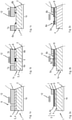
- the Figures 1a to 1c show the example of a first embodiment of a cable 1 in chronological order the steps of the method according to the invention.
- the cable 1 comprises a conductor structure 3 embodied as an inner conductor 4 and an outer cable jacket 7, with a cable foil 6, which consists of a plastic, being arranged between the inner conductor 4 and the cable jacket 7.
- the cable film 6 is accordingly on the as Inner conductor 4 formed conductor structure 3 applied.
- the cable 1 also has a cable axis 2, which represents an axis of symmetry for the cable structure.
- an end section 1b of the cable 1 in which a section 6a of the cable foil 6 to be removed is to be removed from the inner conductor 4 in order to expose a section of the inner conductor 4 .
- the end section 1b of the cable 1 is arranged in sections within an induction coil 12 in order to be able to carry out the inductive heat treatment described below.
- Figure 1b shows the end section 1b during or immediately after the inductive heat treatment by means of the induction coil 12.
- the induction coil 12 heats the inner conductor 4, ie the conductor structure 3 on which the cable foil 6 is applied, inductively. Due to the heating of the inner conductor 4 in a defined area, the cable foil 6 is thermally damaged in a correspondingly defined damage area S.
- the thermal damage can be, for example, a local melting, fusing or melting of the plastic of the cable foil 6 in the damage area S, especially if it is a thermoplastic material. It is also conceivable that the plastic of the cable foil 6 in the damage area S is burned off, degraded or embrittled by the thermal damage, in particular if it is a non-thermoplastic plastic.
- an area is defined in which a movement of the cable foil 6 relative to the inner conductor 4 forms a tear which divides the cable foil 6 into a section 6a to be removed and into a remaining section 6b.
- the section 6a of the cable foil 6 to be removed can be removed from the underlying conductor structure 3, namely the inner conductor 4, if possible without residues of the cable foil 6 remaining in the area of the inner conductor 4 to be exposed.
- the end section 1b is delimited at one end by a cable end 1a, ie an end face of the cable 1.
- the end of the end section 1b opposite the cable end can coincide with the incision 9 and/or the damage area S or can also comprise a section of the cable 1 in which the remaining section 7a of the cable jacket 7 is arranged.
- the incision 9 in the cable jacket 7 is arranged closer to the cable end 1a than the damage area S, so that the cable jacket 7 is intact in that section of the cable 1 that is inside the induction coil 12 during the inductive heat treatment. Since the heat treatment takes place inductively, the damaged area S can be produced without the cable jacket 7 having to be removed in the area to be processed beforehand. By offsetting the incision 9 and the damage area S, it is also possible to ensure that any residues of the cable foil 6 that remain on the inner conductor when it is removed are covered by the cable jacket 7, so that the stripped area of the inner conductor 4 is in any case free of plastic residues that would impede contact.
- the cable 1 is shown during a pull-off movement of the cable foil 6, with a crack having already formed in the damage area S, which has expanded or enlarged as a result of the pull-off, i.e. the movement of the cable foil 6 in the direction of the cable end 1a.
- the Cable foil 6 usually adheres to the cable sheath 7 or the adhesion between cable sheath 7 and cable foil 6 is greater than between cable foil 6 and the underlying conductor structure 3, here on the inner conductor 4. Accordingly, the section 7a of the cable sheath 7 to be removed and the removing portion 6a of the cable foil 6 is removed together by a common relative movement. This also makes it easier to grip the cable foil 6, since the cable sheath 7 can be gripped and moved using a suitable removal tool.
- the relative movement that leads to the formation of the crack does not (exclusively) necessarily have to be a translatory movement, but that a rotary movement or buckling are also conceivable.
- the sections 6a, 7a to be removed from the cable foil 6 and the cable jacket 7 are removed after the crack has formed, preferably by means of a translatory pull-off movement in the direction of the cable end 1a.
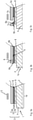
- the cable 1 in the first exemplary embodiment comprises only a single conductor structure 3, namely the inner conductor 4
- the cable 1 in the second exemplary embodiment has an inner conductor 4 and an outer conductor structure 5, namely a metal mesh 5a designed as a braided shield.
- the cable foil 6 is not applied directly to the inner conductor 4, but to the outer conductor structure 5, ie the metal mesh 5a.
- an inner insulating layer 8 is arranged between inner conductor 4 and metal mesh 5a.
- the penetration depth can be selected by means of the induction coil 12 by appropriate selection of the induction parameters, such as amplitude and frequency of the induction current, so that the metal mesh 5a in particular is heated in the damage area S, so that the cable foil 6 located on the metal mesh 5a in the damage area S is thermally damaged. It is particularly advantageous if the insulation layer 8 has a higher thermal resistance than the cable foil 6 in order to prevent the insulation layer 8 in the damage area S from being significantly thermally damaged.
- the cable 1 has three conductor structures 3, namely an inner conductor 4 and two outer conductor structures 5 on.
- the first outer conductor structure 5a is a metal mesh 5a designed as a braided shield, which is applied to an insulating layer 8 .
- a second outer conductor structure in the form of a metal foil 5b is located on the metal mesh 5a.
- the cable foil 6 is applied to the metal foil 5b, it also being conceivable for the metal foil 5b and the cable foil 6 to be in the form of a composite foil.
- This cable structure is a typical cable structure of a coaxial cable, in which the metal mesh 5a acts as a shield mesh.
- Figure 3b shows that the incision 9 can be made before, after or during the inductive heating of the metal foil 5b by means of the induction coil 12, but in the same processing device 10 (see FIG Figures 4 to 6 ).
- the penetration depth can be selected by appropriate selection of the induction parameters, such as amplitude and frequency of the induction current, so that the metal foil 5b in particular is heated in the damage area S, so that the cable foil 6 located on the metal foil 5b in the damage area S is thermally damaged.
- the metal mesh 5a is exposed by removing the sections 6a, 7a of the cable foil 6 and the cable sheath 7 that are to be removed.
- a tear also forms in the metal foil 5b in the damage area S, so that the metal foil 5b, together with the cable jacket 7 and cable foil 6 can be peeled off from the portion of the end portion 1b of the cable 1 to be exposed.
- the joint removal can be achieved particularly easily with a composite foil, but it is also conceivable that the thermal damage to the cable foil 6 reduces the tensile resistance of the metal foil 5b in such a way that during the relative movement due to the high adhesion between the cable foil 6 and metal foil 5b a crack forms in the metal foil 5b.
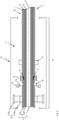
- Processing device 10 shown is intended to illustrate the functioning of the method according to the invention.
- the processing device 10 delimits a processing space 11, in which processing space 11 an end section 1b of a cable 1 to be processed is accommodated, and has at least one passage opening 16 for inserting the end section 1b.
- the structure of the cable 1 corresponds to that in connection with the Figures 3a to 3c described structure, so that the cable 1 comprises an inner conductor 4, an insulation layer 8, a metal mesh 5a designed as a braided shield and a metal foil 5b, a plastic foil 6 applied to the metal foil 5b and a cable jacket 7 in the order given below.
- the induction coil 12 is arranged in the processing space 11 with the end portion 1b passing through the induction coil 12 is, so that at least that area of the cable 1 in which the damage area S is to be generated is arranged within the induction coil 12 . Furthermore, to fix the end section 1b of the cable 1, at least one clamping unit 15 is provided in the processing space 11, by means of which the end section 1b can be clamped during processing.
- the clamping unit 15 preferably comprises one or more clamping elements made of plastic so that they can be positioned in the vicinity of the induction coil 12 .
- the processing device 10 also includes a cutting unit 14 with at least one cutting element 14a for making an incision 9 in the cable jacket 7 and means 13 for pulling off the section 6a of the cable foil 6 to be removed.
- the means 13 for pulling off include a gripping element 13a, which is designed to grip the cable sheath 7 or the cable foil 6, and a movement device 13b, by means of which the gripping elements 13a as soon as they grip the cable sheath 7 or the cable foil 6 have moved relative to the cable 1, preferably can be shifted or twisted.
- the end figure 4 shows the first step of the method, namely the provision of an end section 1b of a cable 1, which has at least one conductor structure 3 and in which a cable film 6 made of plastic is applied to one of the conductor structures 3.
- the clamping unit 15 is already in a state that is clamping the remaining section 7b of the cable sheath 7, and the gripping elements 13a are in engagement with the section 7a of the cable sheath 7 that is to be removed.
- the induction coil 12 is in relation to the cable axis 2 between the means 13 for peeling off the cable foil 6 and the clamping unit 15 in order to fix the section of the cable 1 to be processed.
- figure 5 now shows the step of generating the defined damage area S by that conductor structure 3, im present, the metal foil 5b, which is in contact with the cable foil 6, is inductively heated by means of the induction coil 12, so that the cable foil 6 is thermally damaged in the damage area S.
- the geometry of the induction coil 12, which is preferably water-cooled, and the induction parameters, such as amplitude and frequency as well as the heating duration, are selected in such a way that an electromagnetic alternating field is generated in the induction coil 12 Penetration depth a maximum heating of the metal foil 5b is reached.
- the cable foil 6 Since the metal foil 5b withstands a significantly higher thermal load than the plastic cable foil 6 applied to it due to the material properties, the cable foil 6 is thermally damaged in the damage area S by the inductive heating of the metal foil 5b, for example melted or embrittled or degraded. In order to achieve such thermal damage, the cable foil 6 is brought to a temperature of between 120° C. and 200° C. in the damage area S by means of the inductively heated metal foil 5b. The duration of the inductive heating is advantageously less than 20 s, preferably less than 10 s.
- the metal foil 5b is designed to be structurally weakened by the inductive heating, so that a defined formation of cracks in the metal foil 5b in the damage region S is achieved.
- the cable jacket 7 can be completely intact during the heating, since the alternating electromagnetic field can penetrate the cable jacket 7 without this leading to heating or being impeded by the cable jacket 7 .
- End sections 1b of cables 1 with different diameters and cable structures can also be processed by means of an induction coil 12, since only the parameters of the alternating electromagnetic field have to be set accordingly.
- the end section 1b is shown after the creation of an incision 9 in the cable jacket 7 by means of the cutting unit 14.
- the cutting elements 14a penetrate in the radial direction into the cable jacket 7, the cutting elements 14a being designed to produce an at least partially, preferably completely, circumferential incision 9.
- the portion 7a of the cable sheath 7 to be removed can be pushed toward the cable end 1a by the cutting unit 14 to enlarge the incision 9 in the axial direction.
- the cutting unit 14 is arranged between the means 13 for pulling off the cable foil 6, in particular between the gripping elements 13a, and the induction coil 12, so that the section between the incision 9 and the cable end 1a is less than the distance between the cable end 1a and the induction coil 12 Seen from the passage opening 16 , the induction coil 12 is positioned between the passage opening 16 and the cutting unit 14 .
- Appropriate positioning of the cutting unit 14 ensures that any remnants of the cable foil 6 remaining in the damage area S during the subsequent relative movement and removal are covered by the remaining section 7b of the cable sheath 7 and thus do not adversely affect contacting of the metal mesh 5a.
- the described positioning of the cutting unit 14 ensures that the cable sheath 7 is intact in that area of the cable 1 in which the damage area S is generated by the induction coil 12 is.
- the cutting unit 14 is not necessarily a required part of the Processing device 10, since the incision 9 can also be made before the insertion of the end section 1b into the processing space 11 or the cable sheath 7 can be removed in the section to be processed before insertion.
- FIG 7 the step of moving the cable foil 6 relative to the conductor structures 3 remaining on the cable 1, namely relative to the inner conductor 4 and the metal mesh 5a, is shown. Due to the relative movement, which can be a translational movement, a twisting movement or a buckling movement, a tear forms in the cable foil 6 in the damage area S, which tear separates the section 6a to be removed and the remaining section 6b of the cable foil 6 from one another . Furthermore, a crack also forms in the metal foil 5b in the damage area S, so that the metal foil 5b can then also be removed together with the sections 6a, 7a of cable foil 6 and cable jacket 7 to be removed in order to expose the metal mesh 5a for contacting.
- the relative movement which can be a translational movement, a twisting movement or a buckling movement
- a tear forms in the cable foil 6 in the damage area S, which tear separates the section 6a to be removed and the remaining section 6b of the cable foil 6 from one another .
- a crack also forms in the
- the movement of the gripping elements 13a which clamp the section 7a of the cable sheath 7 to be removed, also clamps the section 6a to be removed of the cable foil 6 adhering to the cable sheath 7 and the metal foil 5b adhering to the cable foil 6, in particular if the cable foil 6 and Metal foil 5b are formed as a composite film, moved relative to the metal mesh 5a to form the crack.
- the crack will form as a result of the thermal damage to the cable foil 6 .
- the removing sections 6a, 7a of the cable foil 6 and cable jacket 7 and of the metal foil 5b can be completely removed from the cable in a simple manner, preferably by the means 13 for pulling 1 be deducted in order to expose the metal braiding 5a designed as a braided shield.
- processing device 10 described above can be used to process cables with cable structures that are shown in the exemplary embodiments described in detail above, as well as cables with cable structures that have one or more intermediate layers.
- the cutting unit 14 can be arranged in a further processing space of a cutting device of the processing device 10 and/or the means 13 for removing the cable foil 6 can be arranged in a further processing space of a stripping device of the processing device 10, while the induction coil 12 and preferably the clamping unit 15 are in the processing space 11 is arranged.
Landscapes
- Physics & Mathematics (AREA)
- Optics & Photonics (AREA)
- Engineering & Computer Science (AREA)
- Manufacturing & Machinery (AREA)
- Processing Of Terminals (AREA)
- Removal Of Insulation Or Armoring From Wires Or Cables (AREA)
- Insulated Conductors (AREA)
- Details Of Cutting Devices (AREA)
Description
- Die Erfindung betrifft ein Verfahren zum Entfernen eines Abschnitts einer Kabelfolie von einem Endabschnitt eines Kabels, wobei das Kabel einen Kabelmantel sowie zumindest eine elektrisch leitfähige Leiterstruktur und die auf einer der Leiterstrukturen aufgebrachte Kabelfolie aus einem Kunststoff umfasst sowie eine Bearbeitungsvorrichtung zur Durchführung des Verfahrens.
- Unter dem Begriff elektrisch leitfähige Leiterstruktur bzw. Leiterstruktur wird dabei im Lichte der gegenständlichen Anmeldung eine, vorzugsweise metallische, Struktur verstanden, welche geeignet ist elektrischen Strom zu leiten und in welche mittels eines elektromagnetischen Felds Kreisströme bzw. Wirbelströme induziert werden können. Entsprechend umfasst der Begriff Leiterstruktur sowohl Innenleiter, wie beispielsweise Vollleiter oder Litzenleiter, als auch äußere Leiterstrukturen, wie beispielsweise Leitergeflechte oder elektrisch leitfähige Folien, vorzugsweise Metallfolien.
- In der Regel umfassen Kabel, insbesondere wenn sie einen Innenleiter als innere Leiterstruktur und eine oder mehrere äußere Leiterstrukturen umfassen, eine oder mehrere weitere Isolationsschichten, wobei die äußere Isolationsschicht als Kabelmantel bezeichnet wird. Zwischen einer der Leiterstrukturen und der darüber liegenden Isolationsschicht kann eine Kabelfolie aus Kunststoff angeordnet sein, welche zum mechanischen Schutz, zur elektromagnetischen Abschirmung oder zum Feuchtigkeitsschutz dienen kann. Insbesondere bei Kabeln, welche einen Innenleiter und ein Schirmgeflecht als äußere Leiterstruktur umfassen, kann die Kabelfolie zwischen Schirmgeflecht und Kabelmantel angeordnet sein, um ein Abziehen des Kabelmantels zu ermöglichen, da sich der Kabelmantel ohne Kabelfolie mit dem darunter liegenden Schirmgeflecht verhaken würde.
- Um die unter der Kabelfolie liegenden Leiterstruktur freizulegen, sodass die Leiterstruktur beispielsweise kontaktiert werden kann, sind - aufgrund der geringen Stärke der Kabelfolie im Vergleich zu Kabelmantel, Innenleiter oder weiteren Isolationsschichten - spezielle Maßnahmen erforderlich, da ein einfaches Einschneiden eine darunter liegende Leiterstruktur, insbesondere ein Schirmgeflecht, und/oder eine, insbesondere unterhalb der Leiterstruktur liegende, Isolationsschicht beschädigen könnte.
- In diesem Zusammenhang wird unter dem Begriff Endabschnitt eines Kabels jener Bereich eines Kabels verstanden, welcher sich von einem Ende entlang einer Kabelachse zumindest über jenen Bereich erstreckt, in welchem die Leiterstrukturen zur Kontaktierung freigelegt sind oder freigelegt werden sollen. Man spricht auch von einem Kontaktierungsabschnitt oder einem abisolierten bzw. abzuisolierenden Abschnitt des Kabels. In der Regel umfasst der Endabschnitt auch noch einen an den abisolierten Abschnitt des Kabels grenzenden Abschnitt, in welchem der Kabelmantel intakt ist, welcher vorzugsweise zwischen 1 cm und 25 cm, besonders bevorzugt zwischen 5 cm und 15 cm, lang ist. Der zu entfernende Abschnitt der Kabelfolie erstreckt sich dabei üblicher Weise über einen Teil des Endabschnitts des Kabels, vorzugsweise beginnend am Kabelende des Endabschnitts.
- Die
EP 3 444 911 A1 offenbart ein Verfahren zum Entfernen einer Kabelfolie, bei welcher zuerst ein zu bearbeitender Abschnitt der Kabelfolie freigelegt wird und dieser freigelegte Abschnitt nachfolgend im Bereich einer vorgesehenen Rissposition einer thermischen, abrasiven oder chemischen Behandlung unterzogen wird. Für die thermische Behandlung wird ein erhitztes Formwerkzeug oder ein Heizdraht erwähnt, mittels welcher die Kabelfolie an- oder abgeschmolzen werden kann. - Die
JP 2018 207624 A - Die
DE 10 2017 221115 B3 zeigt eine Vorrichtung mittels welcher ein endseitiger Teilabschnitt eines Kabelmantels eines Kabels durch induktive Erhitzung erweicht wird, um den Teilabschnitt durch ein Abisolierwerkzeug mechanisch zu entfernen. - Die
CN 207 765 892 U offenbart eine Vorrichtung zum Abisolieren eines Kabels, bei welcher das Kabel durch eine Heizspule geführt ist, um darin den Kabelmantel aufzuweichen und dadurch die Schneiden der Abisoliermesser zu schonen und ihre Abnutzung zu verringern. - Ein Nachteil des Stands der Technik äußert sich nun darin, dass zur Entfernung des zu entfernenden Abschnitts der Kabelfolie einerseits zwingend der Kabelmantel teilweise entfernt werden muss. Andererseits erfordert das vorgeschlagene Verfahren eine komplizierte Vorrichtung, welche entweder eine Drehung des Kabels zur gleichmäßigen Erhitzung erfordert oder ein speziell auf das zu bearbeitende Kabel angepasstes erhitzbares Formwerkzeug.
- Es ist daher eine Aufgabe der Erfindung die Nachteile des Stands der Technik zu überwinden und ein Verfahren sowie eine Bearbeitungsvorrichtung vorzuschlagen, welche eine einfache, sichere und schnelle Entfernung eines zu entfernenden Abschnitts einer Kabelfolie für Endabschnitte von Kabeln mit unterschiedlichen Durchmessern ermöglicht. Eine weitere Aufgabe besteht darin, eine abschnittsweise Entfernung der Kabelfolie zu ermöglichen, ohne dass die Kabelfolie vor der Behandlung freigelegt werden muss.
- Diese Aufgabe wird in einem erfindungsgemäßen Verfahren zum Entfernen eines zu entfernenden Abschnitts einer Kabelfolie von einem Endabschnitt eines eine Kabelachse aufweisenden Kabels erreicht, welches die Merkmale des unabhängigen Anspruchs 1 oder des unabhängigen Anspruchs 2 umfasst.
- Die erfindungsgemäße Lösung zeichnet sich dadurch aus, dass die gezielte Schädigung der Kabelfolie in einem definierten Schädigungsbereich nicht durch direkte Wärmebeaufschlagung erfolgt, sondern dass die - bezogen auf die Kabelachse - unterhalb der Kabelfolie liegenden Leiterstruktur induktiv und somit berührungsfrei erhitzt wird. Es ist durch den induktiven Wärmeeintrag möglich, die Wärme direkt in jenem Bereich zu erzeugen, in welchem sie zur Vorschädigung der Kabelfolie benötigt wird. Andere Bereiche des Kabels, insbesondere der Kabelmantel, werden dabei nicht oder zumindest nicht signifikant erwärmt. Weiters erfolgt der Wärmeeintrag völlig berührungsfrei, sodass es nicht erforderlich ist den Kabelmantel im Schädigungsbereich vor der Wärmebehandlung zu entfernen. Gleichfalls führt die berührungsfreie Erhitzung dazu, dass es beim Entfernen der Kabelfolie zu keiner mechanischen Beschädigung der unteren Schicht bzw. Schichten kommt. Es versteht sich jedoch von selbst, dass die induktive Erhitzung auch auf einer bereits freigelegten Kabelfolie angewendet werden kann, auch wenn dies erfindungsgemäß nicht vorgesehen ist.
- Ein weiterer Vorteil des erfindungsgemäßen Verfahrens besteht darin, dass durch die induktive Erhitzung in einfacher Art und Weise die Kabelfolie in einem genau definierten Schädigungsbereich erhitzt werden kann, wobei sich der Schädigungsbereich der Kabelfolie - ohne dass eine weitere Manipulation des Kabels notwendig ist - bezogen auf einen Querschnitt des Kabels vorzugsweise über den gesamten Umfang erstreckt. Mit anderen Worten ist durch die induktive Erhitzung, mittels welcher die Leiterstruktur in einem definierten Bereich im Wesentlichen gleichmäßig aufgeheizt werden kann, eine vollumfängliche thermische Schädigung der Kabelfolie möglich.
- Es soll dabei nicht unerwähnt bleiben, dass je nach spezifischem elektrischen Widerstand der Leiterstruktur die Induktionsparameter, wie Heizleistung und Haltezeit, entsprechend gewählt werden können, um die Eindringtiefe und die Temperatur einzustellen. Weitere Parameter, welche zur Beeinflussung der Induktionsparameter herangezogen werden können, sind die Frequenz und Amplitude des durch den Induktor fließenden Wechselstroms sowie die geometrische Gestaltung des Induktors. Der Schädigungsbereich kann dabei durch die Einstellung jenes Bereichs, in welchem die maximale Temperatur erreicht wird, besonders genau definiert werden.
- Durch die gezielte thermische Schädigung der Kabelfolie im Schädigungsbereich wird jene Position des Kabels festgelegt, in welcher die Kabelfolie und/oder gegebenenfalls die darunter liegende Leiterstruktur, wenn diese ebenfalls entfernt werden soll, beim Abziehen einreißt. Das Relativbewegen der Kabelfolie gegenüber einer der Leiterstrukturen, vorzugsweise gegenüber der freizulegenden Leiterstruktur, kann durch Abziehen der Kabelfolie bewerkstelligt werden. Beim Abziehen wird die Kabelfolie direkt oder unter Zwischenlage einer weiteren Schicht in Richtung der Kabelachse, sprich in Richtung einer Stirnseite des Endabschnitts, auch Kabelende genannt, bewegt. Es ist jedoch auch denkbar, dass die Relativbewegung eine Torsionsbewegung oder eine Knickbewegung ist, durch welche sich der Riss ausbildet. In einem weiteren Schritt kann der durch den Riss definierte zu entfernende Abschnitt, vorzugsweise durch Abziehen, vom Kabel entfernt werden. Es ist dabei nicht zwingend erforderlich, dass die Schritte der induktiven Erhitzung und des Relativbewegens unmittelbar nacheinander im selben Bearbeitungsraum erfolgen, da diese Schritte auch in verschiedenen Bearbeitungsräumen, etwa die induktive Erhitzung in einem Bearbeitungsraum einer Induktionseinheit und die Relativbewegung in einem weiteren Bearbeitungsraum einer Abmantelungseinrichtung, räumlich getrennt voneinander durchgeführt werden können.
- Unter dem Begriff "thermisch geschädigt" ist sowohl ein Anschmelzen, Aufschmelzen oder Plastifizieren der Kabelfolie als auch ein Abbrennen, ein Verbrennen, ein Verspröden oder eine Degradierung der Kabelfolie zu verstehen, wobei die Art der thermischen Schädigung im Wesentlichen vom Material der Kabelfolie sowie der Dauer und der Höhe der Wärmeeinbringung abhängig ist. Ist die Kabelfolie im Schädigungsbereich nach der induktiven Wärmebehandlung geschmolzen, teilweise geschmolzen, versprödet oder wiedererstarrt, so bildet sich der Riss bei der Relativbewegung bzw. beim Abziehen in der Kabelfolie aus. Ist die Kabelfolie durch die Erhitzung verbrannt bzw. abgebrannt, so liegt der Riss bereits vor dem Abziehen vor und wird durch das Abziehen lediglich vergrößert.
- So ist es beispielsweise denkbar, dass durch die induktive Erhitzung eine als Innenleiter ausgebildete Leiterstruktur erhitzt wird, um eine auf dem Innenleiter aufgebrachte Kabelfolie im Schädigungsbereich zumindest teilweise aufzuschmelzen, um die Kabelfolie vom Innenleiter entfernen zu können.
- Ebenfalls versteht es sich von selbst, dass die induktive Erhitzung jener Leiterstruktur, auf der die Kabelfolie aufgebracht ist, auch dann erfolgen kann, wenn das Kabel zwei oder mehrere Leiterstrukturen umfasst. Dabei kann es auch zu einer induktiven Erhitzung jener Leiterstrukturen kommen, auf denen keine Kabelfolie aufgebracht ist. Aufgrund der geringen Dicke der Kabelfolie kommt es jedoch zu einer definierten Schädigung im Bereich der Kabelfolie während andere Schichten in der Regel nicht signifikant beeinflusst werden. Weiters kann die Erhitzung jener Leiterstrukturen, auf denen keine Kabelfolie aufgebracht ist, durch geeignete Wahl der Induktionsparameter reduziert werden, wobei insbesondere der Skin-Effekt bei hohen Frequenzen ausgenützt werden kann.
- Das Kabel weist eine Kabelachse auf, welche bezogen auf einen Querschnitt des Kabels die Symmetrieachse darstellt. Es versteht sich dabei von selbst, dass die Kabelachse jeweils normal auf den entsprechenden Querschnitt des Kabels steht und entsprechend auch kurvenförmig verlaufen kann, wenn das Kabel gebogen ist. In der Regel ist der Endabschnitt des Kabels nicht gebogen, sodass die Kabelachse im Endabschnitt geradenförmig verläuft.
- In einer weiteren Ausführungsvariante der Erfindung ist vorgesehen, dass sich die zumindest eine Leiterstruktur aus einem Innenleiter und zumindest einer äußeren Leiterstruktur zusammensetzt, wobei die Kabelfolie auf einer der äußeren Leiterstrukturen aufgebracht ist. Bevorzugt ist die Kabelfolie auf der bezogen auf die Kabelachse äußersten Leiterstruktur aufgebracht, wenn mehr als eine äußere Leiterstruktur vorgesehen ist. Es ist jedoch auch denkbar, dass die Kabelfolie auf einer weiter innen liegenden äußeren Leiterstruktur oder auf dem Innenleiter aufgebracht ist. Gleichfalls ist es denkbar, dass auf mehreren der Leiterstrukturen eine Kabelfolie aufgebracht ist. In allen vorgenannten Fällen ist es vorteilhaft, wenn die Bearbeitung von außen nach innen erfolgt, wobei die unterschiedlichen Bearbeitungsabschnitte in der Regel stufenweise versetzt sind. Es versteht sich dabei von selbst, dass die Kabelfolie auf der äußeren Leiterstruktur aufgebracht ist, wenn lediglich eine äußere Leiterstruktur vorhanden ist.
- Ebenfalls kann vorgesehen sein, dass in diesem Fall auch jene Leiterstrukturen, auf denen keine Kabelfolie aufgebracht ist, durch die induktive Erhitzung erwärmt werden können, wodurch sich gegebenenfalls auch kumulative Effekte erreichen lassen können, wenn zwei äußere Leiterstrukturen direkt übereinander angeordnet sind. Beispielsweise kann die zumindest eine äußere Leiterstruktur ein Metallgeflecht, wie beispielsweise ein Schirmgeflecht, und/oder eine Metallfolie umfassen, insbesondere aus einem Schirmgeflecht und/oder einer Metallfolie bestehen. So ist es etwa denkbar, dass die Kabelfolie auf das Metallgeflecht, insbesondere auf das Schirmgeflecht, aufgebracht ist bzw. das Schirmgeflecht umhüllt und durch das Schirmgeflecht induktiv erhitzt wird, sodass die Kabelfolie zumindest teilweise thermisch geschädigt wird.
- Eine bevorzugte Ausführungsvariante des erfindungsgemäßen Verfahrens sieht vor, dass jene äußere Leiterstruktur, auf welche die Kabelfolie aufgebracht ist, als Metallfolie ausgebildet ist. Durch die verhältnismäßig geringe Dicke der Metallfolie lässt sich diese durch entsprechende Einstellung der Eindringtiefe der induktiven Erhitzung besonders effizient erhitzen. Vorzugsweise handelt es sich bei der Metallfolie um eine Aluminium enthaltende Folie bzw. eine Aluminiumfolie. Dadurch, dass die Metallfolie eine geringe Dicke aufweist und daher in der Regel einen geringen Zugwiderstand bzw. Scherwiderstand aufweist und dass die Kabelfolie im Schädigungsbereich thermisch geschädigt wird, sodass auch die Kabelfolie im Schädigungsbereich keinen nennenswerten steigernden Einfluss mehr auf Zug- und Scherwiderstand hat, führt der Riss in der Kabelfolie bei der Relativbewegung ebenfalls zu einer Rissbildung bzw. Schädigung der Metallfolie im Schädigungsbereich.
- Eine Kombination von Metallfolie und Kabelfolie wird oftmals in Koaxialkabeln verwendet, welche als äußere Leiterstruktur auch ein Schirmgeflecht zur elektromagnetischen Abschirmung aufweisen. Somit kann in einer besonders bevorzugten Ausführungsvariante vorgesehen sein, dass die zumindest eine äußere Leiterstruktur ein Schirmgeflecht und eine Metallfolie umfasst, wobei die Metallfolie direkt auf dem Schirmgeflecht angeordnet ist. Die Kabelfolie wiederum ist direkt auf der Metallfolie aufgebracht. In diesem Anwendungsfall kann es durch die induktive Erhitzung zu einem kumulativen Erwärmungseffekt von Schirmgeflecht und Metallfolie kommen, jedoch steht die erreichbare Erhitzung der äußeren Leiterstruktur in der Regel im Verhältnis zur möglichen Eindringtiefe, sodass die Metallfolie aufgrund der geringeren Dicke stärker erhitzt wird als das Schirmgeflecht.
- Insbesondere ist es bevorzugt, besonders für die Verwendung in Koaxialkabeln, wenn die Metallfolie und die Kabelfolie als Verbundfolie ausgebildet sind.
- In einer weiteren Ausführungsvariante der Erfindung ist vorgesehen, dass die als Metallfolie ausgebildete äußere Leiterstruktur durch die induktive Erhitzung im Schädigungsbereich strukturell geschwächt wird. Wenn die äußere Leiterstruktur, auf welcher die Kabelfolie aufgebracht ist, als Metallfolie ausgebildet ist, so ist es vorteilhaft, wenn die Metallfolie gemeinsam mit der Kabelfolie abgezogen wird. Entsprechend führt eine Ausdehnung des Schädigungsbereichs von der Kabelfolie auf die Metallfolie durch die strukturelle Schwächung der Metallfolie dazu, dass sich auch in der Metallfolie beim Abziehen im Schädigungsbereich ein definierter Riss ausbildet, sodass Metallfolie und Kabelfolie gemeinsam abgezogen werden können, ohne dass Reste auf der darunterliegenden Schicht verbleiben, welche einer etwaigen Kontaktierung hinderlich wären.
- Besonders einfach lässt sich zumindest die entsprechende Leiterstruktur induktiv erhitzen, wenn die induktive Erhitzung mittels einer Induktionsspule erfolgt, mittels welcher Induktionsspule ein elektromagnetisches Wechselfeld erzeugt wird, wobei zumindest der Schädigungsbereich des Kabels während der induktiven Erhitzung innerhalb der Induktionsspule angeordnet wird. Durch die Erzeugung eines elektromagnetischen Wechselfelds in einer, vorzugsweise wassergekühlten, Induktionsspule, können als relevante Parameter für die induktive Erhitzung die Frequenz und Amplitude des durch die Induktionsspule fließenden Wechselstroms angesehen werden. Durch die Verwendung einer Induktionsspule lässt sich auch in besonders einfacher Weise die vollumfängliche Schädigung der Kabelfolie sicherstellen, da zumindest ein Bereich des Endabschnitts des Kabels während der Erhitzung in der Induktionsspule angeordnet ist und die entsprechende Leiterstruktur entsprechend über den gesamten Umfang gleichförmig erhitzt wird.
- Schließlich lässt sich durch die Verwendung einer Induktionsspule, in welcher das zu bearbeitende Kabel zumindest abschnittsweise eingeführt ist, die induktive Erhitzung für eine Vielzahl von unterschiedlichen Kabeldurchmessern bzw. Kabelarten anwenden, solange ein erforderlicher Abstand zwischen Innendurchmesser der Induktionsspule und Außendurchmesser des aufgenommenen Kabelabschnitts eingehalten wird, welcher Abstand beispielsweise als Luftspalt ausgebildet sein kann oder durch ein nichtleitendes Material ausgefüllt sein kann. Dazu ist es in der Regel lediglich erforderlich die Parameter des erzeugten elektromagnetischen Wechselfelds, vorzugsweise über Einstellung von Amplitude und Frequenz des Erregerstroms, bzw. die Eindringtiefe, die Haltezeit und/oder die Heizleistung anzupassen.
- Wenngleich es grundsätzlich auch denkbar ist, dass die induktive Erhitzung auch auf einer bereits freigelegten Kabelfolie angewendet werden kann, ist es vorteilhaft, wenn die Wärmebehandlung durchgeführt werden kann, ohne dass dafür der Kabelmantel im Schädigungsbereich entfernt werden muss. Entsprechend ist erfindungsgemäß weiters vorgesehen, dass die Kabelfolie im Schädigungsbereich während der induktiven Erhitzung der zumindest einen Leiterstruktur vom Kabelmantel abgedeckt wird. Mit anderen Worten ist der Kabelmantel im Schädigungsbereich bzw. im in die Induktionsspule eingeführten Abschnitt des Kabels unversehrt, sodass die Kabelfolie im Inneren des Kabels erhitzt wird. Dies ist nur dank der induktiven Erhitzung der unterhalb der Kabelfolie liegenden Leiterstruktur möglich, da mittels der induktiven Erhitzung die erforderliche Aufheizung nicht von außen erfolgt, sondern direkt dort, wo die Hitze benötigt wird. Anders ausgedrückt wird die Leiterstruktur, auf der die Kabelfolie aufgebracht ist, durch den Kabelmantel hindurch induktiv erhitzt, um den Schädigungsbereich zu erzeugen.
- Um eine Bearbeitung des Kabelmantels zu ermöglichen, sodass der Kabelmantel im Rahmen des Verfahrens von einem abzuisolierenden Abschnitt des Kabelendabschnitts entfernt werden kann, sieht die Erfindung vor, dass das Verfahren weiters den folgenden Schritt umfasst:
- zumindest teilweises umlaufendes Einschneiden des Kabelmantels an einer Position, welche näher an einem Kabelende des Endabschnitts des Kabels, sprich einer Stirnfläche des Endabschnitts, angeordnet ist als der Schädigungsbereich. Durch das Einschneiden des Kabels an einer Position, die zwischen dem Kabelende, sprich der Stirnseite des Endabschnitts des Kabels, und dem Schädigungsbereich liegt, wird erreicht, dass die Stelle, an der die Kabelfolie bzw. gegebenenfalls Kabelfolie und Metallfolie beim Abziehen reißt unterhalb des Kabelmantels liegt. So kann verhindert werden, dass etwaige beim Einreißen zurückbleibende Reste der Kabelfolie nach der Entfernung des zu entfernenden Abschnitts des Kabelmantels auf der freigelegten Leiterstruktur verbleiben, da diese Reste aufgrund der Schnittposition durch den verbleibenden Abschnitt des Kabelmantels verdeckt werden.
- Besonders vorteilhaft ist die oben beschriebene Positionierung des Einschnitts, wenn das Kabel drei Leiterstrukturen, nämlich einen Innenleiter, ein Schirmgeflecht und eine Metallfolie, umfasst, wobei Schirmgeflecht, Metallfolie und Kabelfolie unmittelbar in dieser Reihenfolge übereinander angeordnet sind, es sich also um ein Koaxialkabel handelt. Dies deshalb, da etwaig auf dem Schirmgeflecht verbleibende Reste von Metallfolie und/oder Kabelfolie die Kontaktierung des Schirmgeflechts behindern könnten. Durch die Wahl der Einschneide-Position sind solche Reste von Kabelfolie und/oder Metallfolie auf dem Schirmgeflecht durch den Kabelmantel verdeckt, sodass der tatsächlich freigelegte Abschnitt des Schirmgeflechts rückstandsfrei ist.
- Es ist dabei genauso denkbar, dass das Einschneiden bereits vor dem induktiven Erhitzen des Schädigungsbereichs, gegebenenfalls bereits vor dem Einführen des Endabschnitts in den Bearbeitungsraum einer, Bearbeitungsvorrichtung, erfolgt, wie es denkbar ist, dass das Einschneiden während oder nach der induktiven Wärmebehandlung des Schädigungsbereichs erfolgt. Beispielsweise kann das Einschneiden in einem weiteren Bearbeitungsraum einer Schneideinrichtung erfolgen. Schließlich ist die Entfernung des Kabelmantels kein erforderlicher Schritt für die Durchführung der Wärmebehandlung.
- Wenngleich es - wie zuvor beschrieben - erfindungsgemäß vorgesehen ist, dass der Abstand zwischen der Position des Einschnitts und dem Kabelende geringer ist als der Abstand zwischen Schädigungsbereich und Kabelende, ist es natürlich auch denkbar, aber nicht in den Ansprüchen der vorliegenden Patentschrift beansprucht, dass der Schädigungsbereich in einer nicht beanspruchten Ausführungsvariante näher oder gleich nah am Kabelende angeordnet ist als der Einschnitt, sodass gegebenenfalls ein Abschnitt der Kabelfolie nach dem Abziehen des Kabelmantels freigelegt wird.
- Besonders einfach kann die Kabelfolie dadurch entfernt werden, dass sie gemeinsam mit dem unmittelbar darüber liegenden Kabelmantel vom Endabschnitt des Kabels abgezogen wird, da die Kabelfolie in der Regel eine erhöhte Haftung am Kabelmantel aufweist. Wird also der Kabelmantel, bevorzugt wie oben beschrieben, eingeschnitten, so kann der Kabelmantel mit entsprechenden Mitteln relativ zu einer der Leiterstrukturen, insbesondere relativ zum Innenleiter, bewegt werden, wobei die darunter liegende Kabelfolie bzw. die darunter liegende Kabelfolie und/oder die unterhalb der Kabelfolie liegende Metallfolie im Schädigungsbereich einreißen und gemeinsam mit dem Kabelmantel abgezogen werden können. Bei der Relativbewegung kann es sich wiederum um eine Knickbewegung, eine Drehbewegung und/oder eine Abziehbewegung, also eine Bewegung in Richtung der Kabelachse hin zum Kabelende des Endabschnitts, handeln. Die gemeinsame Entfernung von zu entfernendem Abschnitt des Kabelmantels und zu entfernendem Abschnitt der Kabelfolie erfolgt durch Abziehen des zu entfernenden Abschnitts des Kabelmantels. Daher sieht eine weitere Ausführungsvariante der Erfindung vor, dass der Kabelmantel durch einen zumindest teilweise umlaufenden, vorzugsweise vollständig umlaufenden, Einschnitt in einen zu entfernenden Abschnitt des Kabelmantels und einen verbleibenden Abschnitt des Kabelmantels unterteilt ist und dass der zu entfernende Abschnitt des Kabelmantels in Richtung der Kabelachse bewegt wird, wobei durch die Bewegung der zumindest teilweise am Kabelmantel anhaftende zu entfernende Abschnitt der Kabelfolie abgezogen wird.
- Wenngleich es grundsätzlich denkbar ist, dass die zuvor beschriebenen Verfahrensschritte in unterschiedlichen Bearbeitungsräumen sequentiell hintereinander ausgeführt werden, ist es besonders vorteilhaft, wenn die entsprechenden Schritte in einem Bearbeitungsraum einer gemeinsamen Bearbeitungsvorrichtung, welche in der Folge im Detail beschrieben wird, durchgeführt werden. Gemäß einer weiteren Ausführungsvariante der Erfindung ist daher vorgesehen, dass die Schritte
- induktives Erhitzen zumindest jener Leiterstruktur auf welcher die Kabelfolie aufgebracht ist;
- zumindest teilweises umlaufendes Einschneiden des Kabelmantels;
- gemeinsames Entfernen eines zu entfernenden Abschnitts des Kabelmantels und des zu entfernenden Abschnitts der Kabelfolie, vorzugsweise durch Abziehen, in einem Bearbeitungsraum einer Bearbeitungsvorrichtung durchgeführt werden.
- Als besonders vorteilhaft hat es sich erwiesen, dass die Kabelfolie auf eine in einem bevorzugten Temperaturbereich liegende Temperatur erhitzt wird, welche Temperatur durch die Temperatur der darunter liegenden induktiv erhitzten Leiterstruktur eingestellt werden kann. Daher ist in einer weiteren Ausführungsvariante vorgesehen, dass die zumindest eine Leiterstruktur auf eine Temperatur größer gleich 80°C, bevorzugt größer gleich 100°C, besonders bevorzugt größer gleich 200°C, insbesondere größer gleich 300°C, induktiv erhitzt wird. Die Messung der Temperatur kann beispielsweise mittels eines Pyrometers erfolgen. Die Temperatur der induktiv erhitzten Leiterstruktur und die Dauer der induktiven Erhitzung, beispielsweise weniger als 30 s, insbesondere weniger als 20 s, bevorzugt weniger als 10 s, können in Abhängigkeit von Materialeigenschaften der Kabelfolie, beispielsweise der Dicke und/oder der Art des Kunststoffes, eingestellt werden, um die thermische Schädigung zu erreichen.
- Die eingangs erwähnte Aufgabe wird auch gelöst durch eine Bearbeitungsvorrichtung zur Durchführung des erfindungsgemäßen Verfahrens gemäß Anspruch 10.
- Neben den eingangs erwähnten Vorteilen der induktiven Erhitzung der zumindest einen Leiterstruktur zur Erzeugung eines Schädigungsbereichs in der Kabelfolie bzw. gegebenenfalls in Kabelfolie und darunter liegender Metallfolie, wird durch die Kombination von induktiver Wärmebehandlung und Abziehen der Kabelfolie in einer Bearbeitungsvorrichtung die Anzahl der notwendigen Manipulationsvorgänge reduziert und eine effiziente Entfernung der Kabelfolie ermöglicht. Dabei ist es für einen Bearbeitungsvorgang lediglich erforderlich, den zu bearbeitenden Abschnitt des Kabels in die Induktionsspule einzuführen. Es ist jedoch denkbar, dass der zu entfernende Abschnitt der Kabelfolie durch die vorgesehenen Mittel nicht vollständig sondern nur teilweise abgezogen wird.
- Bei den Mitteln zum Abziehen des zu entfernenden Abschnitts der Kabelfolie kann es sich beispielsweise um translatorisch bewegbare Greif- und/oder Bewegungselemente handeln, welche die Kabelfolie direkt fassen und relativ zu einer unter der Kabelfolie liegenden Schicht, beispielsweise zu einem Innenleiter oder einem Schirmgeflecht, verschieben und/oder verdrehen können. Es ist dabei denkbar, dass durch die Mittel zum Abziehen mehrere Bewegungen hintereinander durchgeführt werden können, beispielsweise eine Verdreh- oder Knickbewegung zur Herstellung eines Risses im Schädigungsbereich der Kabelfolie und eine nachfolgenden lineare Abziehbewegung zur Entfernung des zu entfernenden Abschnitts der Kabelfolie, gegebenenfalls gemeinsam mit einem zu entfernenden Abschnitt des Kabelmantels. Ebenfalls ist es denkbar, dass die Mittel zum Abziehen als entsprechend ausgebildete Kabelfolienentfernungs-Einrichtung ausgebildet sind.
- Es ist jedoch, wie in der Folge näher beschrieben, nicht zwingend erforderlich, dass die Mittel zum Abziehen der Kabelfolie die Kabelfolie direkt kontaktieren. So können die Mittel zum Abziehen der Kabelfolie beispielsweise durch eine Schneideinheit zur Herstellung eines Einschnittes im Kabelmantel ausgebildet sein, welche nach dem Einschnitt auch eine Relativbewegung in Richtung der Kabelachse ausführen kann.
- Mit anderen Worten kann es sich bei dem Mittel zum Abziehen der Kabelfolie um eine Einrichtung handeln, welche derart ausgebildet ist, dass zumindest der zu entfernende Abschnitt der Kabelfolie, vorzugsweise gemeinsam mit einem zu entfernenden Abschnitt des Kabelmantels, relativ zu einer der Leiterstrukturen, vorzugsweise relativ zu einem Metallgeflecht oder dem Innenleiter, bewegt werden kann, sodass sich zumindest in der Kabelfolie im Schädigungsbereich ein Riss ausbildet.
- Die Mittel zum Abziehen eines Abschnitts der Kabelfolie müssen dabei, insbesondere wenn die Bearbeitungsvorrichtung als Anlage mit mehreren Teileinrichtungen ausgebildet ist, nicht zwingend in jenem Bearbeitungsraum angeordnet sein, in welchem auch die Induktionsspule angeordnet ist. So ist es auch denkbar, dass die Mittel zum Abziehen eines Abschnitts der Kabelfolie beispielsweise in einem weiteren Bearbeitungsraum einer Abmantelungseinrichtung der Bearbeitungsvorrichtung, vorzugsweise der Anlage, angeordnet sind.
- Grundsätzlich können in einer solchen Vorrichtung sowohl Endabschnitte eines Kabels behandelt werden, in denen die Kabelfolie bereits durch Entfernung des Kabelmantels freigelegt wurde als auch Endabschnitte von Kabeln mit intaktem Kabelmantel bearbeitet werden, sofern entweder eine Schneideinheit vorgesehen ist oder der Kabelmantel vor dem Einführen in die Bearbeitungsvorrichtung bereits eingeschnitten wurde.
- Es soll auch nicht unerwähnt bleiben, dass eine Induktionsspule, welche eingerichtet ist, um eine Leiterstruktur induktiv zu erhitzen, sodass die auf der erhitzten Leiterstruktur aufgebrachte Kabelfolie in einem Schädigungsbereich zumindest teilweise thermisch geschädigt wird, in der Regel auch geeignet ist, eine auf der erhitzten Leiterstruktur aufgebrachte nichtmetallische Zwischenschicht zu erhitzen und thermisch zu schädigen, welche nicht aus Kunststoff bestehen. Beispielsweise kann es sich bei solchen nichtmetallischen Zwischenschichten um, vorzugsweise mit Harz getränkte, Gewebestrukturen, beispielsweise aus Stoffen wie Baumwolle oder aus Papier, handeln. Derartige nichtmetallische Zwischenschichten sind üblicher Weise ausgelegt, um eine darunter liegende als Metallfolie ausgebildete äußere Leiterstruktur vor dem Reißen zu schützen. Ebenfalls ist eine entsprechend ausgebildete Induktionsspule auch geeignet sein kann, um eine auf der erhitzten Leiterstruktur aufgebrachte Klebeschicht thermisch zu schädigen.
- In einer weiteren Ausführungsvariante der Erfindung ist vorgesehen, dass im Bearbeitungsraum zumindest eine Klemmeinheit zur Fixierung des Endabschnitts des Kabels während des Bearbeitungsvorganges angeordnet ist. Die zumindest eine Klemmeinheit umfasst vorzugsweise zumindest ein Klemmelement, welches vorzugsweise aus Kunststoff gefertigt ist, um im Nahbereich der Induktionsspule positioniert werden zu können. Mittels der Klemmeinheit kann der Endabschnitt des Kabels effizient fixiert werden, um sowohl die induktive Wärmebehandlung als auch das Relativbewegen der Kabelfolie relativ zu einer der Leiterstrukturen, vorzugsweise relativ zu einem Innenleiter, zu ermöglichen, ohne dass sich das Kabel dabei relativ zum Bearbeitungsraum bewegt.
- Gemäß einer der Erfindung ist vorgesehen, dass die Bearbeitungsvorrichtung weiters eine Schneideinheit zum zumindest teilweise umlaufenden Einschneiden des Kabelmantels umfasst. Da der Kabelmantel für die Durchführung der induktiven Erhitzung der zumindest einen Leiterstruktur im Schädigungsbereich nicht freigelegt sein muss, kann das Einschneiden und gegebenenfalls nachfolgende Entfernen des Kabelmantels direkt in der Bearbeitungsvorrichtung erfolgen, insbesondere wenn die Mittel zum Abziehen die Schneideinheit umfassen.
- Die Schneideinheit kann beispielsweise zumindest ein Schneidelement, vorzugsweise zumindest zwei, genau zwei oder mehr als zwei, Schneidelemente aufweisen, welche während der Schneidbewegung in radialer Richtung in den Kabelmantel eindringen, um einen zumindest teilweise, vorzugsweise vollständig, umlaufenden Einschnitt zu erzeugen.
- Die beanspruchte Ausführung der erfindungsgemäßen Bearbeitungsvorrichtung sieht vor, dass die Schneideinheit im Bearbeitungsraum angeordnet ist, wobei der Bearbeitungsraum eine Durchtrittsöffnung für das Kabel aufweist und die Induktionsspule zwischen Schneideinheit und Durchtrittsöffnung angeordnet ist. Vorzugsweise ist die Schneideinheit zwischen den Mitteln zum Abziehen und der Induktionsspule angeordnet.
- Durch eine entsprechende Anordnung der Schneideinheit im Bearbeitungsraum, in welchem auch die Induktionsspule angeordnet ist, wird erreicht, dass der teilweise umlaufende Einschnitt im Kabelmantel an einer Position erfolgt, welche näher an einem Kabelende des Kabels angeordnet ist als der durch die induktive Erhitzung der entsprechenden Leiterstruktur erzeugte Schädigungsbereich. Da der Endabschnitt des Kabels in der Regel nur einen kleinen Abschnitt der Gesamtlänge des Kabels ausmacht, ist üblicher Weise eine Durchtrittsöffnung für das Kabel im Bearbeitungsraum vorgesehen, durch welche der zu bearbeitende Abschnitt des Kabels in den Bearbeitungsraum eingeführt werden kann bzw. durch welchen der nicht zu bearbeitende Abschnitt des Kabels aus dem Bearbeitungsraum geführt werden kann. Um also die Position des Einschnitts im Kabelmantel relativ zum Schädigungsbereich, in welchem Kabelfolie bzw. Kabelfolie und Metallfolie beim Abziehen einreißen, für den zu bearbeitenden Endabschnitt eines Kabels in der Bearbeitungsvorrichtung zu definieren, ist die Induktionsspule, welche den Schädigungsbereich erzeugt, zwischen Schneideinheit und Durchtrittsöffnung angeordnet.
- Um eine einfache Entfernung des zu entfernenden Abschnitts der Kabelfolie zu ermöglichen, welche einerseits nicht erfordert, dass der Kabelmantel im Schädigungsbereich vor der induktiven Erhitzung der Leiterstruktur entfernt werden muss, und andererseits eine besonders einfache Manipulation ermöglicht, ist gemäß einer weiteren Ausführungsvariante der Erfindung vorgesehen, dass die Mittel zum Abziehen des zu entfernenden Abschnitts der Kabelfolie ausgebildet sind, um einen durch einen Einschnitt definierten zu entfernenden Abschnitt des Kabelmantels zu kontaktieren und nachfolgend den zu entfernenden Abschnitt des Kabelmantels gemeinsam mit einem zu entfernenden Abschnitt der Kabelfolie, welcher vorzugsweise am Kabelmantel anhaftet, mittels einer Abziehbewegung zu entfernen. Der Einschnitt im Kabelmantel kann dabei entweder mit der zuvor erwähnten Schneideinheit vorgenommen werden oder der Einschnitt kann bereits im eingeführten Endabschnitt des Kabels vorhanden sein.
- Die Mittel zur Entfernung des Endabschnitts der Kabelfolie können wiederum als Greifelemente oder Schiebeelemente ausgebildet sein, die jedoch nicht die dünne Kabelfolie kontaktieren und fassen müssen, sondern den stärkeren Kabelmantel. Durch das Greifen und Relativbewegen, beispielsweise Schieben, Ziehen, Verdrehen oder Knicken, des zu entfernenden Abschnitts des Kabelmantels relativ zu einer der Leiterstrukturen, vorzugsweise relativ zum Innenleiter, wird auch die darunter liegende und zumindest teilweise am Kabelmantel anhaftende Kabelfolie gespannt, sodass die Kabelfolie im Schädigungsbereich reißt und nachfolgend abgezogen werden kann. Die Abziehbewegung, welche eine Bewegung des zu entfernenden Abschnitts des Kabelmantels in Richtung des Kabelendes umfasst, kann entweder gleichzeitig auch zur Risserzeugung verwendet werden oder erst nach der Risserzeugung, mittels einer zuvor durchgeführten Relativbewegung, erfolgen. Handelt es sich beim induktiv erhitzten Leiter um eine Metallfolie, so kann sich der Riss auch in der Metallfolie ausbilden, sodass Metallfolie und Kabelfolie gemeinsam mit dem zu entfernenden Abschnitt des Kabelmantels von der darunter liegenden Schicht des Kabels, insbesondere von einem Schirmgeflecht, abgezogen werden können, um diese Schicht, insbesondere das Schirmgeflecht, freizulegen.
- In einer weiteren Ausführungsvariante der Erfindung ist vorgesehen, dass die Mittel zum Abziehen des zu entfernenden Abschnitts der Kabelfolie im Bearbeitungsraum angeordnet sind. Durch die Anordnung von mehreren Komponenten der Bearbeitungsvorrichtung in jenem Bearbeitungsraum, in welchem die Induktionsspule angeordnet ist, wird eine besonders kompakte Bauweise ermöglicht, welche die Durchführung von mehreren Verfahrensschritten in einem Bearbeitungsraum ermöglicht. Besonders bevorzugt sind daher sowohl die Induktionsspule als auch die Schneideinheit und die Mittel zum Abziehen der Kabelfolie in einem gemeinsamen Bearbeitungsraum angeordnet.
- Die Erfindung wird nun anhand von Ausführungsbeispielen näher erläutert. Die Zeichnungen sind beispielhaft und sollen den Erfindungsgedanken zwar darlegen, ihn aber keinesfalls einengen oder gar abschließend wiedergeben.
- Dabei zeigt:
- Fig. 1a bis 1c
- den schematischen Ablauf des erfindungsgemäßen Verfahrens an Hand eines Endabschnitts eines ersten Ausführungsbeispiels eines Kabels;
- Fig. 2a bis 2c
- den schematischen Ablauf eines nicht beanspruchten Verfahrens an Hand des Endabschnitts eines zweiten Ausführungsbeispiels des Kabels;
- Fig. 3a bis 3c
- den schematischen Ablauf des erfindungsgemäßen Verfahrens an Hand des Endabschnitts eines dritten Ausführungsbeispiels des Kabels;
- Fig. 4
- einen Endabschnitt des Kabels in einer Bearbeitungsvorrichtung;
- Fig. 5
- den Endabschnitt des Kabels in der Bearbeitungsvorrichtung nach der induktiven Erhitzung;
- Fig. 6
- den Endabschnitt des Kabels nach dem Einschneiden;
- Fig. 7
- den Endabschnitt des Kabels in der Bearbeitungsvorrichtung während des Abziehens.
- Die
Figuren 1a bis 1c zeigen am Beispiel eines ersten Ausführungsbeispiels eines Kabels 1 in zeitlicher Abfolge die Schritte des erfindungsgemäßen Verfahrens. Im ersten Ausführungsbeispiel umfasst das Kabels 1 eine als Innenleiter 4 ausgebildete Leiterstruktur 3 sowie einen äußeren Kabelmantel 7, wobei zwischen Innenleiter 4 und Kabelmantel 7 eine Kabelfolie 6, welche aus einem Kunststoff besteht, angeordnet ist. Die Kabelfolie 6 ist entsprechend auf der als Innenleiter 4 ausgebildeten Leiterstruktur 3 aufgebracht. Das Kabel 1 weist weiters eine Kabelachse 2 auf, welche eine Symmetrieachse für den Kabelaufbau darstellt. - Dargestellt ist dabei ein Endabschnitt 1b des Kabels 1, in welchem ein zu entfernender Abschnitt 6a der Kabelfolie 6 vom Innenleiter 4 entfernt werden soll, um einen Abschnitt des Innenleiters 4 freizulegen. Der Endabschnitt 1b des Kabels 1 ist abschnittsweise innerhalb einer Induktionsspule 12 angeordnet, um die nachfolgend beschriebene induktive Wärmebehandlung durchführen zu können.
- Im vorliegenden Ausführungsbeispiel weist der Kabelmantel 7, wie in
Figur 1a dargestellt, im Endabschnitt 1b bereits zu Beginn des Verfahrens einen Einschnitt 9 auf, welcher den Kabelmantel 7 in einen zu entfernenden Abschnitt 7a (sieheFig. 1b ) und einen verbleibenden Abschnitt 7b unterteilt. -
Figur 1b zeigt den Endabschnitt 1b während bzw. unmittelbar nach der induktiven Wärmebehandlung mittels der Induktionsspuke 12. Mittels der Induktionsspule 12 wird der Innenleiter 4, also jene Leiterstruktur 3, auf welcher die Kabelfolie 6 aufgebracht ist, induktiv erhitzt. Durch die Erhitzung des Innenleiters 4 in einem definierten Bereich wird die Kabelfolie 6 in einem entsprechend definierten Schädigungsbereich S thermisch geschädigt. - Bei der thermischen Schädigung kann es sich beispielsweise um ein lokales Anschmelzen, Aufschmelzen oder Abschmelzen des Kunststoffes der Kabelfolie 6 im Schädigungsbereich S handeln, insbesondere wenn es sich um einen thermoplastischen Kunststoff handelt. Ebenfalls ist es denkbar, dass der Kunststoff der Kabelfolie 6 im Schädigungsbereich S durch die thermische Schädigung abgebrannt, degradiert oder versprödet wird, insbesondere wenn es sich um einen nicht thermoplastischen Kunststoff handelt.
- Durch die thermische Schädigung der Kabelfolie 6 im Schädigungsbereich S wird ein Bereich definiert, in welchem sich bei einer Bewegung der Kabelfolie 6 relativ zum Innenleiter 4 ein Riss ausbildet, welcher die Kabelfolie 6 in einen zu entfernenden Abschnitt 6a und in einen verbleibenden Abschnitt 6b teil. Durch den mittels des Schädigungsbereichs S definierten Riss kann der zu entfernende Abschnitt 6a der Kabelfolie 6 von der darunter liegenden Leiterstruktur 3, nämlich dem Innenleiter 4, entfernt werden, möglichst ohne dass Reste der Kabelfolie 6 im freizulegenden Bereich des Innenleiters 4 zurückbleiben.
- Der Endabschnitt 1b wird von einem Kabelende 1a, sprich einer Stirnfläche des Kabels 1, an einem Ende begrenzt. Das dem Kabelende gegenüberliegende Ende des Endabschnitts 1b kann mit dem Einschnitt 9 und/oder dem Schädigungsbereich S zusammenfallen oder kann noch einen Abschnitt des Kabels 1 umfassen, in welchem der verbleibende Abschnitt 7a des Kabelmantels 7 angeordnet ist.
- Im vorliegenden Ausführungsbeispiel ist der Einschnitt 9 im Kabelmantel 7 näher am Kabelende 1a angeordnet als der Schädigungsbereich S, sodass der Kabelmantel 7 in jenem Abschnitt des Kabels 1, welcher sich während der induktiven Wärmebehandlung innerhalb der Induktionsspule 12 befindet, intakt ist. Da die Wärmebehandlung induktiv erfolgt, kann der Schädigungsbereich S hergestellt werden, ohne dass zuvor der Kabelmantel 7 im zu bearbeitenden Bereich entfernt werden muss. Durch den Versatz von Einschnitt 9 und Schädigungsbereich S kann weiters erreicht werden, dass etwaige beim Entfernen am Innenleiter zurückbleibende Reste der Kabelfolie 6 durch den Kabelmantel 7 verdeckt sind, sodass der abisolierte Bereich des Innenleiters 4 jedenfalls frei von die Kontaktierung behindernden Kunststoffresten ist.
- In
Figur 1c ist das Kabel 1 während einer Abziehbewegung der Kabelfolie 6 dargestellt, wobei sich im Schädigungsbereich S bereits ein Riss ausgebildet hat, welcher sich durch das Abziehen, sprich durch die Bewegung der Kabelfolie 6 in Richtung des Kabelendes 1a, ausgedehnt bzw. vergrößert hat. Im vorliegenden Ausführungsbeispiel wird ausgenützt, dass die Kabelfolie 6 in der Regel am Kabelmantel 7 anhaftet bzw. die Haftung zwischen Kabelmantel 7 und Kabelfolie 6 größer ist als zwischen Kabelfolie 6 und der darunter liegenden Leiterstruktur 3, hier am Innenleiter 4. Entsprechend werden der zu entfernende Abschnitt 7a des Kabelmantels 7 und der zu entfernende Abschnitt 6a der Kabelfolie 6 gemeinsam durch eine gemeinsame Relativbewegung entfernt. Dies ermöglicht auch ein einfacheres Greifen der Kabelfolie 6, da durch ein entsprechendes Abziehwerkzeug der Kabelmantel 7 gegriffen und bewegt werden kann. - Es soll dabei nicht unerwähnt bleiben, dass es sich bei der Relativbewegung, die zur Ausbildung des Risses führt, nicht (ausschließlich) zwangsläufig um eine translatorische Bewegung handeln muss, sondern auch eine Drehbewegung oder ein Knicken denkbar sind. Die Entfernung der zu entfernenden Abschnitte 6a,7a von Kabelfolie 6 und Kabelmantel 7 nach der Rissbildung erfolgt vorzugsweise durch eine translatorische Abziehbewegung in Richtung des Kabelendes 1a.
- Nach der Entfernung der zu entfernenden Abschnitte 6a,7a von Kabelfolie 6 und Kabelmantel 7 verbleibt ein Kabel 1, in dessen Endbereich 1b der Innenleiter 4 zur Kontaktierung freigelegt ist.
- In den
Figuren 2a bis 2c werden die bereits im Zusammenhang mit dem ersten Ausführungsbeispiel diskutierten Schritte des erfindungsgemäßen Verfahrens gezeigt, weshalb lediglich auf die Unterschiede des zweiten Ausführungsbeispiels im Vergleich zum ersten Ausführungsbeispiel im Detail eingegangen wird. - Während das Kabel 1 im ersten Ausführungsbeispiel lediglich eine einzige Leiterstruktur 3, nämlich den Innenleiter 4, umfasst, weist das Kabel 1 im zweiten Ausführungsbeispiel einen Innenleiter 4 und eine äußere Leiterstruktur 5, nämlich ein als Schirmgeflecht ausgebildetes Metallgeflecht 5a, auf. Die Kabelfolie 6 ist dabei nicht direkt auf dem Innenleiter 4 aufgebracht, sondern auf der äußeren Leiterstruktur 5, sprich dem Metallgeflecht 5a. Um eine Kontaktierung von Metallgeflecht 5a und Innenleiter 4 zu verhindern, ist zwischen Innenleiter 4 und Metallgeflecht 5a eine innere Isolationsschicht 8 angeordnet.
- Weiters ist insbesondere in
Fig. 2b zu erkennen, dass im vorliegenden nicht beanspruchten Ausführungsbeispiel der zu entfernende Abschnitt 7a des Kabelmantels 7a bereits vor dem Einführen des Endabschnitts 1b in die Induktionsspule 12 entfernt wurde. Wenngleich dies - wie zuvor erwähnt nicht unbedingt erforderlich ist - funktioniert die induktive Erhitzung der äußeren Leiterstruktur 5 natürlich auch, wenn kein Abschnitt des Kabelmantels 7 in der Induktionsspule 12 zwischen der zu erhitzenden Leiterstruktur 3,5,5a und der Induktionsspule 12 vorhanden ist. Mittels der Induktionsspule 12 kann im vorliegenden Ausführungsbeispiel durch entsprechende Wahl der Induktionsparameter, wie Amplitude und Frequenz des Induktionsstromes, die Eindringtiefe so gewählt werden, dass insbesondere das Metallgeflecht 5a im Schädigungsbereich S erhitzt wird, sodass die auf dem Metallgeflecht 5a befindliche Kabelfolie 6 im Schädigungsbereich S thermisch geschädigt wird. Dabei ist es insbesondere vorteilhaft, wenn die Isolationsschicht 8 einen höheren thermischen Widerstand aufweist als die Kabelfolie 6, um zu verhindern, dass auch die Isolationsschicht 8 im Schädigungsbereich S signifikant thermisch geschädigt wird. - In
Figur 2c ist dargestellt, dass der zu entfernende Abschnitt 6a der Kabelfolie 6 durch Relativbewegen von Kabelfolie 6 zu Metallgeflecht 5a vom Endabschnitt 1b entfernt wird. - Die
Figuren 3a bis 3c zeigen die zuvor beschriebenen Schritte des erfindungsgemäßen Verfahrens im Zusammenhang mit einer besonders bevorzugten dritten Ausführungsvariante. Wiederum wird in der Folge lediglich auf die Unterschiede zu den zuvor beschriebenen Ausführungsvarianten eingegangen. - In diesem Ausführungsbeispiel weist das Kabel 1 drei Leiterstrukturen 3, nämlich einen Innenleiter 4 und zwei, äußere Leiterstrukturen 5, auf. Bei der ersten äußeren Leiterstruktur 5a handelt es sich - wie auch beim zweiten Ausführungsbeispiel - um ein als Schirmgeflecht ausgebildetes Metallgeflecht 5a, welches auf einer Isolationsschicht 8 aufgebracht ist. Auf dem Metallgeflecht 5a befindet sich eine zweite äußere Leiterstruktur in Form einer Metallfolie 5b. Die Kabelfolie 6 ist im vorliegenden Ausführungsbeispiel auf der Metallfolie 5b aufgebracht, wobei auch denkbar ist, dass Metallfolie 5b und Kabelfolie 6 als Verbundfolie ausgebildet sind. Es handelt sich bei diesem Kabelaufbau um einen typischen Kabelaufbau eines Koaxialkabels, bei welchem das Metallgeflecht 5a als Schirmgeflecht fungiert.
- In
Figur 3a ist zu erkennen, dass der Kabelmantel 7 beim Einführen des Endabschnitts 1b in die Induktionsspule 12 vollkommen intakt ist, also auch kein Einschnitt 9 vorgesehen ist. -
Figur 3b zeigt, dass der Einschnitt 9 vor, nach oder während der induktiven Erhitzung der Metallfolie 5b mittels der Induktionsspule 12 hergestellt werden kann, jedoch in der selben Bearbeitungsvorrichtung 10 (sieheFiguren 4 bis 6 ). Mittels der Induktionsspule 12 im vorliegenden Ausführungsbeispiel kann durch entsprechende Wahl der Induktionsparameter, wie Amplitude und Frequenz des Induktionsstromes, die Eindringtiefe so gewählt werden, dass insbesondere die Metallfolie 5b im Schädigungsbereich S erhitzt wird, sodass die auf der Metallfolie 5b befindliche Kabelfolie 6 im Schädigungsbereich S thermisch geschädigt wird. - Nachfolgend wird, wie in
Figur 3c zu erkennen ist, das Metallgeflecht 5a durch Entfernen von den zu entfernenden Abschnitten 6a,7a von Kabelfolie 6 und Kabelmantel 7 freigelegt. Dabei bildet sich beim Relativbewegen von Kabelmantel 7 und Kabelfolie 6 relativ zum Innenleiter 4 bzw. zum Metallgeflecht 5a auch in der Metallfolie 5b im Schädigungsbereich S ein Riss aus, sodass auch die Metallfolie 5b gemeinsam mit Kabelmantel 7 und Kabelfolie 6 vom freizulegenden Abschnitt des Endabschnitts 1b des Kabels 1 abgezogen werden kann. Die gemeinsame Entfernung lässt sich besonders einfach bei einer Verbundfolie erreichen, jedoch ist es auch denkbar, dass durch die thermische Schädigung der Kabelfolie 6 der Zugwiderstand der Metallfolie 5b derart verringert wird, dass sich bei der Relativbewegung aufgrund der hohen Haftung zwischen Kabelfolie 6 und Metallfolie 5b ein Riss in der Metallfolie 5b ausbildet. - Es versteht sich von selbst, dass die zuvor beschriebenen Ausführungsbeispiele, insbesondere im Hinblick auf die Kabelaufbauten und die Positionen der Einschnitte 9, ohne Weiteres miteinander kombiniert werden können. Auch können zusätzliche Schichten, sowohl Isolationsschichten 8 als auch Leiterstrukturen, vorgesehen sein, wobei die zuvor beschriebene Freilegung von Innenleiter 4 und/oder Metallgeflechten 5a stufenartig mit den zuvor beschriebenen Schritten wiederholt werden kann.
- An Hand der in den
Figuren 4 bis 7 dargestellten Bearbeitungsvorrichtung 10 soll die Funktionsweise des erfindungsgemäßen Verfahrens verdeutlicht werden. Die Bearbeitungsvorrichtung 10 begrenzt dabei einen Bearbeitungsraum 11, in welchem Bearbeitungsraum 11 ein Endabschnitt 1b eines zu bearbeitenden Kabels 1 aufgenommen ist, und weist zumindest eine Durchtrittsöffnung 16 zum Einführen des Endabschnitts 1b auf. Der Aufbau des Kabels 1 entspricht dabei dem im Zusammenhang mit denFiguren 3a bis 3c beschriebenen Aufbau, sodass das Kabel 1 in der nachfolgend angegebenen Reihenfolge einen Innenleiter 4, eine Isolationsschicht 8, ein als Schirmgeflecht ausgebildetes Metallgeflecht 5a sowie eine Metallfolie 5b, eine auf der Metallfolie 5b aufgebrachte Kunststofffolie 6 sowie einen Kabelmantel 7 umfasst. - Die Induktionsspule 12 ist im Bearbeitungsraum 11 angeordnet, wobei der Endabschnitt 1b durch die Induktionsspule 12 geführt ist, sodass zumindest jener Bereich des Kabels 1, in welchem der Schädigungsbereich S erzeugt werden soll, innerhalb der Induktionsspule 12 angeordnet ist. Weiters ist zur Fixierung des Endabschnitts 1b des Kabels 1 zumindest eine Klemmeinheit 15 im Bearbeitungsraum 11 vorgesehen mittels welcher der Endabschnitt 1b während der Bearbeitung geklemmt werden kann. Die Klemmeinheit 15 umfasst vorzugsweise ein oder mehrere Klemmelemente aus Kunststoff, sodass diese im Nahbereich der Induktionsspule 12 positioniert werden können.
- Weiters umfasst die Bearbeitungsvorrichtung 10 eine Schneideinheit 14 mit zumindest einem Schneidelement 14a zur Herstellung eines Einschnitts 9 im Kabelmantel 7 sowie Mittel 13 zum Abziehen des zu entfernenden Abschnitts 6a der Kabelfolie 6 auf. Die Mittel 13 zum Abziehen umfassen dabei im vorliegenden Ausführungsbeispiel ein Greifelement 13a, welches ausgebildet ist, um den Kabelmantel 7 oder die Kabelfolie 6 zu greifen, sowie eine Bewegungseinrichtung 13b, mittels welcher die Greifelemente 13a, sobald sie den Kabelmantel 7 oder die Kabelfolie 6 umgriffen haben, relativ zum Kabel 1 bewegt, vorzugsweise verschoben oder verdreht werden können.
- Aus
Figur 4 ist der erste Schritt des Verfahrens ersichtlich, nämlich das Bereitstellen eines Endabschnitts 1b eines Kabels 1, welches zumindest eine Leiterstruktur 3 aufweist und bei welchem eine Kabelfolie 6 aus Kunststoff auf einer der Leiterstrukturen 3 aufgebracht ist. Im gezeigten Zustand der Bearbeitungsvorrichtung 10 befindet sich die Klemmeinheit 15 bereits in einem den verbleibenden Abschnitt 7b des Kabelmantels 7 klemmenden Zustand und die Greifelemente 13a sind im Eingriff mit dem zu entfernenden Abschnitt 7a des Kabelmantels 7. Die Induktionsspule 12 ist bezogen auf die Kabelachse 2 zwischen dem Mittel 13 zum Abziehen der Kabelfolie 6 und der Klemmeinheit 15 angeordnet, um den zu bearbeitenden Abschnitt des Kabels 1 zu fixieren. -
Figur 5 zeigt nun den Schritt des Erzeugens des definierten Schädigungsbereichs S, indem jene Leiterstruktur 3, im vorliegenden die Metallfolie 5b, welche mit der Kabelfolie 6 in Kontakt steht, mittels der Induktionsspule 12 induktiv erhitzt wird, sodass die Kabelfolie 6 im Schädigungsbereich S thermisch geschädigt wird. Um eine solche definierte Schädigung zu erreichen, werden die Geometrie der, vorzugsweise wassergekühlten, Induktionsspule 12 sowie die Induktionsparameter, wie Amplitude und Frequenz sowie Heizdauer, so gewählt, dass in der Induktionsspule 12 ein elektromagnetisches Wechselfeld erzeugt wird, wobei mittels der durch das Wechselfeld darstellbaren Eindringtiefe eine maximale Erhitzung der Metallfolie 5b erreicht wird. Da die Metallfolie 5b aufgrund der Materialeigenschaften einer wesentlich höheren thermische Belastung standhält als die darauf aufgebrachte Kabelfolie 6 aus Kunststoff, wird die Kabelfolie 6 im Schädigungsbereich S durch die induktive Erhitzung der Metallfolie 5b thermisch geschädigt, beispielsweise geschmolzen oder versprödet bzw. degradiert. Um eine solche thermische Schädigung zu erreichen, wird die Kabelfolie 6 mittels der induktiv erhitzten Metallfolie 5b im Schädigungsbereich S auf eine zwischen 120°C und 200°C liegende Temperatur gebracht. Die Dauer der induktiven Erhitzung beträgt vorteilhafter Weise weniger als 20s, bevorzugt weniger als 10s. - Es ist in alternativen Ausführungsbeispielen auch denkbar, dass die Metallfolie 5b ausgelegt ist, um durch die induktive Erhitzung strukturell geschwächt zu werden, sodass eine definierte Rissbildung der Metallfolie 5b im Schädigungsbereich S erreicht wird.
- Durch die induktive Erhitzung kann der Kabelmantel 7 während der Erhitzung vollständig intakt sein, da das elektromagnetische Wechselfeld den Kabelmantel 7 durchdringen kann, ohne dass dies zu einer Erhitzung führen würde oder durch den Kabelmantel 7 behindert werden würde. Auch können mittels einer Induktionsspule 12 Endabschnitte 1b von Kabeln 1 mit unterschiedlichen Durchmessern und Kabelaufbau bearbeitet werden, da lediglich die Parameter des elektromagnetischen Wechselfeldes entsprechend eingestellt werden müssen.
- In
Figur 6 ist der Endabschnitt 1b nach dem Erzeugen eines Einschnitts 9 im Kabelmantel 7 mittels der Schneideeinheit 14 dargestellt. Dabei dringen die Schneideelemente 14a in radialer Richtung in den Kabelmantel 7 ein, wobei die Schneideelemente 14a ausgebildet sind, um einen zumindest teilweise, vorzugsweise vollständig, umlaufenden Einschnitt 9 herzustellen. Wenn die Schneideeinheit 14, wie dargestellt, verschiebbar in der Bearbeitungsvorrichtung 10 gehalten ist, kann der zu entfernende Abschnitt 7a des Kabelmantels 7 mittels der Schneideinheit 14 in Richtung des Kabelendes 1a verschoben werden, um den Einschnitt 9 in axialer Richtung zu vergrößern. - Die Schneideinheit 14 ist dabei zwischen den Mitteln 13 zum Abziehen der Kabelfolie 6, insbesondere zwischen den Greifelementen 13a, und der Induktionsspule 12 angeordnet, sodass der Abschnitt zwischen Einschnitt 9 und Kabelende 1a geringer ist als der Abstand zwischen Kabelende 1a und Induktionsspule 12. Von der Durchtrittsöffnung 16 aus gesehen ist die Induktionsspule 12 zwischen Durchtrittsöffnung 16 und Schneideinheit 14 positioniert. Eine entsprechende Positionierung der Schneideinheit 14 stellt sicher, dass etwaige beim nachfolgenden Relativbewegen und Abziehen verbleibende Reste der Kabelfolie 6 im Schädigungsbereich S durch den verbleibenden Abschnitt 7b des Kabelmantels 7 verdeckt werden und so eine Kontaktierung des Metallgeflechts 5a nicht negativ beeinflussen.
- Die beschriebene Positionierung der Schneideinheit 14 stellt in alternativen Ausführungsvarianten des Verfahrens, in denen der Einschnitt 9 vor der induktiven Erhitzung erfolgt, sicher, dass der Kabelmantel 7 in jenem Bereich des Kabels 1, in welchem der Schädigungsbereich S mittels der Induktionsspule 12 erzeugt wird, intakt ist.
- Wie bereits im Zusammenhang mit den in den
Figuren 1a bis 3c gezeigten Ausführungsbeispielen erwähnt, ist die Schneideinheit 14 nicht unbedingt ein erforderlicher Teil der Bearbeitungsvorrichtung 10, da der Einschnitt 9 auch bereits vor dem Einführen des Endabschnitts 1b in den Bearbeitungsraum 11 hergestellt werden kann oder der Kabelmantel 7 im zu bearbeitenden Abschnitt bereits vor dem Einführen entfernt sein kann. - In
Figur 7 ist der Schritt des Bewegens der Kabelfolie 6 relativ zu den am Kabel 1 verbleibenden Leiterstrukturen 3, nämlich relativ zum Innenleiter 4 und zum Metallgeflecht 5a, dargestellt. Durch die Relativbewegung, bei der es sich um eine translatorische Bewegung, eine Verdrehbewegung oder eine Knickbewegung handeln kann, bildet sich im Schädigungsbereich S ein Riss in der Kabelfolie 6 aus, welcher den zu entfernenden Abschnitt 6a und den verbleibenden Abschnitt 6b der Kabelfolie 6 voneinander trennt. Weiters bildet sich im Schädigungsbereich S auch ein Riss in der Metallfolie 5b aus, sodass nachfolgend auch die Metallfolie 5b gemeinsam mit den zu entfernenden Abschnitten 6a,7a von Kabelfolie 6 und Kabelmantel 7 entfernt werden kann, um das Metallgeflecht 5a zur Kontaktierung freizulegen. - Im vorliegenden Ausführungsbeispiel wird durch die Bewegung der Greifelemente 13a, welche den zu entfernenden Abschnitt 7a des Kabelmantels 7 klemmen, auch der zu entfernende Abschnitt 6a der am Kabelmantel 7 anhaftenden Kabelfolie 6 sowie die an der Kabelfolie 6 anhaftenden Metallfolie 5b, insbesondere wenn Kabelfolie 6 und Metallfolie 5b als Verbundfolie ausgebildet sind, relativ zum Metallgeflecht 5a bewegt, um den Riss auszubilden. Der Riss wird sich in der Regel von der thermischen Schädigung der Kabelfolie 6 ausgehend ausbilden.
- Sobald der Riss im Schädigungsbereich S in Metallfolie 5b und Kabelfolie 6 ausgebildet ist, können die entfernenden Abschnitte 6a,7a von Kabelfolie 6 und Kabelmantel 7 sowie von der Metallfolie 5b in einfacher Art und Weise, vorzugsweise durch die Mittel 13 zum Abziehen, vollständig vom Kabel 1 abgezogen werden, um das als Schirmgeflecht ausgebildete Metallgeflecht 5a freizulegen.
- Es soll nicht unerwähnt bleiben, dass mittels der zuvor beschriebenen Bearbeitungsvorrichtung 10 sowohl Kabel mit Kabelaufbauten, die in den zuvor detailliert beschriebenen Ausführungsbeispielen gezeigt werden, als auch Kabel mit Kabelaufbauten, die eine oder mehrere Zwischenschichten aufweisen, entsprechend bearbeitet werden können.
- Auch wenn in den
Figuren 4 bis 7 alle relevanten Elemente der Bearbeitungsvorrichtung 10 der besseren Nachvollziehbarkeit halber in einem gemeinsamen Bearbeitungsraum 11 angeordnet dargestellt sind, was zusätzlich eine besonders kurze Gesamtdauer für die Entfernung des zu entfernenden Abschnitts 6a der Kabelfolie 6 bewirkt, kann in alternativen Ausführungsvarianten der Erfindung, insbesondere wenn die Bearbeitungsvorrichtung 10 als Anlage mit mehreren Teileinrichtungen ausgebildet ist, vorgesehen sein, dass Schneideinheit 14 und/oder die Mittel 13 zum Abziehen der Kabelfolie 6 in jeweils getrennten weiteren Bearbeitungsräumen angeordnet sind. So kann die Schneideinheit 14 in einem weiteren Bearbeitungsraum einer Schneideinrichtung der Bearbeitungsvorrichtung 10 angeordnet sein und/oder die Mittel 13 zum Abziehen der Kabelfolie 6 in einem weiteren Bearbeitungsraum einer Abmantelungseinrichtung der Bearbeitungsvorrichtung 10 angeordnet sein, während die Induktionsspule 12 sowie vorzugsweise die Klemmeinheit 15 im Bearbeitungsraum 11 angeordnet ist. -
- 1
- Kabel
1a Kabelende
1b Endabschnitt - 2
- Kabelachse
- 3
- Leiterstruktur
- 4
- Innenleiter
- 5
- äußere Leiterstruktur
5a Metallgeflecht
5b Metallfolie - 6
- Kabelfolie
- 6a
- zu entfernender Abschnitt der Kabelfolie 6
- 6b
- verbleibender Abschnitt der Kabelfolie 6
- 7
- Kabelmantel
7a zu entfernender Abschnitt des Kabelmantels 7
7b verbleibender Abschnitt des Kabelmantels 7 - 8
- Isolationsschicht
- 9
- Einschnitt
- 10
- Bearbeitungsvorrichtung
- 11
- Bearbeitungsraum
- 12
- Induktionsspule
- 13
- Mittel zum Abziehen der Kabelfolie 13
13a Greifelement
13b Bewegungseinrichtung
14 Schneideinheit
14a Schneidelement
15 Klemmeinheit
16 Durchtrittöffnung
S Schädigungsbereich
Claims (13)
- Verfahren zum Entfernen eines zu entfernenden Abschnitts (6a) einer Kabelfolie (6) von einem Endabschnitt (1b) eines Kabels (1),
umfassend die folgenden Schritte:- Bereitstellen eines Endabschnitts (1b) eines eine Kabelachse (2) aufweisenden Kabels (1), wobei das Kabel (1) einen Kabelmantel (7) sowie zumindest eine elektrisch leitfähige Leiterstruktur (3,4,5) und die auf einer der Leiterstrukturen (3,4,5) aufgebrachte Kabelfolie (6) aus einem Kunststoff umfasst;- Erzeugen eines definierten Schädigungsbereichs (S) im bereitgestellten Endabschnitt (1b) des Kabels (1), indem zumindest jene Leiterstruktur (3,4,5a,5b), auf welcher die Kabelfolie (6) aufgebracht ist, induktiv erhitzt wird, sodass die auf der erhitzten Leiterstruktur (3,4,5a,5b) aufgebrachte Kabelfolie (6) im Schädigungsbereich (S) zumindest teilweise thermisch geschädigt wird,wobei die Kabelfolie (6) im Schädigungsbereich (S) während der induktiven Erhitzung der zumindest einen Leiterstruktur (3,4,5) vom Kabelmantel (7) abgedeckt wird;- zumindest teilweises umlaufendes Einschneiden des Kabelmantels (7) während oder nach der Erzeugung des Schädigungsbereichs (S),wobei das zumindest teilweise Einschneiden an einer Position erfolgt, welche näher an einem Kabelende (1a) des Endabschnitts (1b) angeordnet ist als der Schädigungsbereich (S);- Bewegen der Kabelfolie (6) relativ zu einer der Leiterstrukturen (3,4,5), wobei sich durch die Relativbewegung im Schädigungsbereich (S) ein Riss ausbildet, welcher den zu entfernenden Abschnitt (6a) der Kabelfolie (6) von einem am Kabel (1) verbleibenden Abschnitt (6b) der Kabelfolie (6) trennt. - Verfahren zum Entfernen eines zu entfernenden Abschnitts (6a) einer Kabelfolie (6) von einem Endabschnitt (1b) eines Kabels (1),
umfassend die folgenden Schritte:- Bereitstellen eines Endabschnitts (1b) eines eine Kabelachse (2) aufweisenden Kabels (1), wobei das Kabel (1) einen Kabelmantel (7) sowie zumindest eine elektrisch leitfähige Leiterstruktur (3,4,5) und die auf einer der Leiterstrukturen (3,4,5) aufgebrachte Kabelfolie (6) aus einem Kunststoff umfasst;- Herstellen eines Einschnitts (9) im bereitgestellten Endabschnitt (1b) des Kabels (1) durch zumindest teilweise umlaufendes Einschneiden des Kabelmantels (7);- Erzeugen eines definierten Schädigungsbereichs (S) im Endabschnitt (1b) des Kabels (1), indem zumindest jene Leiterstruktur (3,4,5a,5b), auf welcher die Kabelfolie (6) aufgebracht ist, induktiv erhitzt wird, sodass die auf der erhitzten Leiterstruktur (3,4,5a,5b) aufgebrachte Kabelfolie (6) im Schädigungsbereich (S) zumindest teilweise thermisch geschädigt wird,wobei der Schädigungsbereich (S) nach der Herstellung des Einschnitts (9) erzeugt wird,wobei ein Abstand zwischen einem Kabelende (1a) des Endabschnitts (1b) und dem Schädigungsbereich (S) größer ist als zwischen dem Kabelende (1a) und einer Position des Einschnitts (9),wobei die Kabelfolie (6) im Schädigungsbereich (S) während der induktiven Erhitzung der zumindest einen Leiterstruktur (3,4,5) vom Kabelmantel (7) abgedeckt wird;- Bewegen der Kabelfolie (6) relativ zu einer der Leiterstrukturen (3,4,5), wobei sich durch die Relativbewegung im Schädigungsbereich (S) ein Riss ausbildet, welcher den zu entfernenden Abschnitt (6a) der Kabelfolie (6) von einem am Kabel (1) verbleibenden Abschnitt (6b) der Kabelfolie (6) trennt. - Verfahren nach Anspruch 1 oder 2, wobei sich die zumindest eine Leiterstruktur (3) aus einem Innenleiter (4) und zumindest einer äußeren Leiterstruktur (5,5a,5b) zusammensetzt, wobei die Kabelfolie (6) auf einer der äußeren Leiterstrukturen (5,5a,5b) aufgebracht ist.
- Verfahren nach Anspruch 3, wobei jene äußere Leiterstruktur (5), auf welche die Kabelfolie (6) aufgebracht ist, als Metallfolie (5b) ausgebildet ist.
- Verfahren nach Anspruch 4, wobei die als Metallfolie (5b) ausgebildete äußere Leiterstruktur (5) durch die induktive Erhitzung im Schädigungsbereich (S) strukturell geschwächt wird.
- Verfahren nach einem der Ansprüche 1 bis 5, wobei die induktive Erhitzung mittels einer Induktionsspule (12) erfolgt, mittels welcher Induktionsspule (12) ein elektromagnetisches Wechselfeld erzeugt wird, wobei zumindest der Schädigungsbereich (S) des Kabels (1) während der induktiven Erhitzung innerhalb der Induktionsspule (12) angeordnet wird.
- Verfahren nach einem der Ansprüche 1 bis 6, wobei der Kabelmantel (7) durch einen mittels des Schritts des zumindest teilweise umlaufenden Einschneidens hergestellten Einschnitt (9) in einen zu entfernenden Abschnitt (7a) des Kabelmantels (7) und einen verbleibenden Abschnitt (7b) des Kabelmantels (7) unterteilt ist und dass der zu entfernende Abschnitt (7a) des Kabelmantels (7) in Richtung der Kabelachse (2) bewegt wird, wobei durch die Bewegung der zumindest teilweise am Kabelmantel (7) anhaftende zu entfernende Abschnitt (6a) der Kabelfolie (6) abgezogen wird.
- Verfahren nach einem der Ansprüche 1 bis 7, wobei die Schritte- induktives Erhitzen zumindest jener Leiterstruktur (3,4,5a,5b) auf welcher die Kabelfolie (6) aufgebracht ist;- zumindest teilweise umlaufendes Einschneiden des Kabelmantels (7);- gemeinsames Entfernen eines zu entfernenden Abschnitts (7a) des Kabelmantels (7) und des zu entfernenden Abschnitts (6a) der Kabelfolie (6) in einem Bearbeitungsraum (11) einer Bearbeitungsvorrichtung (10) durchgeführt werden.
- Verfahren nach einem der Ansprüche 1 bis 8, wobei die zumindest eine Leiterstruktur (3,4,5), auf welche die Kabelfolie (6) aufgebracht ist, auf eine Temperatur größer gleich 80°C, bevorzugt größer gleich 100°C, besonders bevorzugt größer gleich 200°C, insbesondere größer gleich 300°C, induktiv erhitzt wird.
- Bearbeitungsvorrichtung (10) zur Durchführung eines Verfahrens nach einem der Ansprüche 1 bis 9 umfassend:- einen Bearbeitungsraum (11) zur Aufnahme eines Endabschnitts (1b) eines zu bearbeitenden Kabels (1), wobei das Kabel (1) einen Kabelmantel (7) sowie zumindest eine elektrisch leitfähige Leiterstruktur (3,4,5) und eine auf einer der Leiterstrukturen (3,4,5) aufgebrachte Kabelfolie (6) aus einem Kunststoff umfasst,wobei der Bearbeitungsraum (11) eine Durchtrittsöffnung (16) für das Kabel (1) aufweist;- eine im Bearbeitungsraum (11) angeordnete Induktionsspule (12);- Mittel (13) zum Abziehen eines durch einen Schädigungsbereich (S) definierten zu entfernenden Abschnitts (6a) der Kabelfolie (6);- eine Schneideinheit (14) zum zumindest teilweise umlaufenden Einschneiden des Kabelmantels (7),dadurch gekennzeichnet, dassdie Induktionsspule (12) eingerichtet ist, ein elektromagnetisches Wechselfeld zu erzeugen, um zumindest jene Leiterstruktur (3,4,5a,5b) eines während eines Bearbeitungsvorganges in der Induktionsspule (12) befindlichen Abschnitts des Kabels (1), auf welcher Leiterstruktur (3,4,5a,5b) die Kabelfolie (6) aufgebracht ist, induktiv zu erhitzen, sodass die auf der erhitzten Leiterstruktur (3,4,5a,5b) aufgebrachte Kabelfolie (6) im Schädigungsbereich (S) zumindest teilweise thermisch geschädigt wird;und dassdie Schneideinheit (14) im Bearbeitungsraum (11) angeordnet ist, wobei die Induktionsspule (12) zwischen Schneideinheit (14) und Durchtrittsöffnung (16) angeordnet ist, und die Schneideinheit (14) dazu eingerichtet ist den Kabelmantel (7) an einer Position einzuschneiden, welche näher an einem Kabelende (1a) des Endabschnitts (1b) angeordnet ist als der Schädigungsbereich (S).
- Bearbeitungsvorrichtung (10) nach Anspruch 10, dadurch gekennzeichnet, dass im Bearbeitungsraum (11) zumindest eine Klemmeinheit (15) zur Fixierung des Endabschnitts (1b) des Kabels (1) während eines Bearbeitungsvorganges angeordnet ist.
- Bearbeitungsvorrichtung (10) nach einem der Ansprüche 10 bis 11, dadurch gekennzeichnet, dass die Mittel (13) zum Abziehen des zu entfernenden Abschnitts (6a) der Kabelfolie (6) ausgebildet sind, um einen durch einen Einschnitt (9) definierten zu entfernenden Abschnitt (7a) des Kabelmantels (7) zu kontaktieren und nachfolgend den zu entfernenden Abschnitt (7a) des Kabelmantels (7) gemeinsam mit einem zu entfernenden Abschnitt (6a) der Kabelfolie (6a) mittels einer Abziehbewegung zu entfernen.
- Bearbeitungsvorrichtung (10) nach einem der Ansprüche 10 bis 12, dadurch gekennzeichnet, dass die Mittel (13) zum Abziehen des zu entfernenden Abschnitts (6a) der Kabelfolie (6) im Bearbeitungsraum (11) angeordnet sind.
Priority Applications (11)
| Application Number | Priority Date | Filing Date | Title |
|---|---|---|---|
| EP19207945.7A EP3820006B1 (de) | 2019-11-08 | 2019-11-08 | Verfahren zum entfernen einer kabelfolie |
| CN202080031679.4A CN113785455B (zh) | 2019-11-08 | 2020-11-05 | 用于去除线缆箔的方法以及加工设备 |
| JP2022521442A JP7657787B2 (ja) | 2019-11-08 | 2020-11-05 | ケーブル箔を除去する方法 |
| KR1020227018384A KR102961978B1 (ko) | 2019-11-08 | 2020-11-05 | 케이블 박막의 제거 방법 |
| DE112020005497.7T DE112020005497A5 (de) | 2019-11-08 | 2020-11-05 | Verfahren zum Entfernen einer Kabelfolie |
| PCT/EP2020/081210 WO2021089744A1 (de) | 2019-11-08 | 2020-11-05 | Verfahren zum entfernen einer kabelfolie |
| DE202020005834.3U DE202020005834U1 (de) | 2019-11-08 | 2020-11-05 | Bearbeitungsvorrichtung zum Entfernen einer Kabelfolie |
| DE202020005837.8U DE202020005837U1 (de) | 2019-11-08 | 2020-11-05 | Bearbeitungsvorrichtung zum Entfernen einer Kabelfolie |
| US17/755,752 US20220393445A1 (en) | 2019-11-08 | 2020-11-05 | Method For Removing A Cable Film |
| MX2022005426A MX2022005426A (es) | 2019-11-08 | 2020-11-05 | Procedimiento para retirar la pelicula de un cable. |
| US19/427,631 US20260112869A1 (en) | 2019-11-08 | 2025-12-19 | Method for removing a cable film |
Applications Claiming Priority (1)
| Application Number | Priority Date | Filing Date | Title |
|---|---|---|---|
| EP19207945.7A EP3820006B1 (de) | 2019-11-08 | 2019-11-08 | Verfahren zum entfernen einer kabelfolie |
Publications (2)
| Publication Number | Publication Date |
|---|---|
| EP3820006A1 EP3820006A1 (de) | 2021-05-12 |
| EP3820006B1 true EP3820006B1 (de) | 2022-03-02 |
Family
ID=68501397
Family Applications (1)
| Application Number | Title | Priority Date | Filing Date |
|---|---|---|---|
| EP19207945.7A Active EP3820006B1 (de) | 2019-11-08 | 2019-11-08 | Verfahren zum entfernen einer kabelfolie |
Country Status (7)
| Country | Link |
|---|---|
| US (2) | US20220393445A1 (de) |
| EP (1) | EP3820006B1 (de) |
| JP (1) | JP7657787B2 (de) |
| CN (1) | CN113785455B (de) |
| DE (3) | DE202020005837U1 (de) |
| MX (1) | MX2022005426A (de) |
| WO (1) | WO2021089744A1 (de) |
Families Citing this family (2)
| Publication number | Priority date | Publication date | Assignee | Title |
|---|---|---|---|---|
| US12088029B2 (en) * | 2021-07-20 | 2024-09-10 | Dell Products L.P. | Cable termination for information handling systems |
| DE202023002310U1 (de) | 2023-06-15 | 2024-06-25 | Feintechnik R. Rittmeyer Gmbh | Vorrichtung zur partiellen Erwärmung von linearen Medien mit metallischen Anteilen mittels magnetischen Wechselfeld |
Citations (1)
| Publication number | Priority date | Publication date | Assignee | Title |
|---|---|---|---|---|
| WO2020188456A1 (en) * | 2019-03-20 | 2020-09-24 | Te Connectivity Corporation | Method of removing foil shield from cable |
Family Cites Families (16)
| Publication number | Priority date | Publication date | Assignee | Title |
|---|---|---|---|---|
| US3765276A (en) * | 1972-03-24 | 1973-10-16 | Western Electric Co | Wire stripper device |
| JP2951359B2 (ja) * | 1989-04-20 | 1999-09-20 | 古河電気工業株式会社 | 光ファイバ用被覆除去装置 |
| JPH0710141B2 (ja) * | 1989-09-21 | 1995-02-01 | 株式会社日立製作所 | ケーブルの端末処理方法およびその端末処理装置 |
| DE4036011C2 (de) * | 1990-11-13 | 1993-11-25 | Horst Schlauteck | Vorrichtung zum Durchtrennen einer metallischen Abschirmung |
| JPH11332050A (ja) * | 1998-05-08 | 1999-11-30 | Miyaden:Kk | リード端末処理方法及びその処理装置 |
| JP4091348B2 (ja) * | 2002-06-10 | 2008-05-28 | 矢崎総業株式会社 | フラットシールド電線のシールド処理構造及びそのシールド処理方法 |
| US9511536B2 (en) * | 2002-10-18 | 2016-12-06 | The Boeing Company | Method and apparatus to assist with removing an adhesive system |
| DE102011004078B4 (de) * | 2011-02-14 | 2012-10-31 | Aloys Wobben | Vorrichtung und Verfahren zum induktiven Abisolieren von Drähten und/oder Profilen |
| US9318884B2 (en) * | 2011-03-30 | 2016-04-19 | Illinois Tool Works Inc. | Induction heating wire insulation heating and removal |
| RS61248B1 (sr) * | 2016-10-18 | 2021-01-29 | Komax Holding Ag | Postupak i uređaj za skidanje izolacije kabla sa višeslojnom oblogom |
| EP3322054B1 (de) * | 2016-11-15 | 2020-06-03 | Schleuniger Holding AG | Vorrichtung und verfahren zum entfernen einer inneren umhüllung elektrischer leiter |
| JP6353586B1 (ja) * | 2017-06-01 | 2018-07-04 | 株式会社岩崎電機製作所 | ケーブル被覆体のストリップ装置 |
| DE102017118445A1 (de) | 2017-08-14 | 2019-02-14 | Metzner Maschinenbau Gmbh | Verfahren und Vorrichtung zum Entfernen einer Kabelfolie |
| EP3447865B1 (de) * | 2017-08-23 | 2022-10-05 | Komax Holding Ag | Verfahren zum entfernen eines teils einer schirmfolie eines mantelleitungskabels und folienentfernungsvorrichtung zum entfernen eines teils einer schirmfolie eines mantelleitungskabels an einer sollbruchstelle von dem mantelleitungskabel |
| CN207765892U (zh) * | 2017-11-13 | 2018-08-24 | 胡朝海 | 一种高效率电气工程用剥线装置 |
| DE102017221115B3 (de) * | 2017-11-27 | 2019-01-31 | Leoni Kabel Gmbh | Verfahren sowie Vorrichtung zum Abisolieren einer Leitung |
-
2019
- 2019-11-08 EP EP19207945.7A patent/EP3820006B1/de active Active
-
2020
- 2020-11-05 CN CN202080031679.4A patent/CN113785455B/zh active Active
- 2020-11-05 DE DE202020005837.8U patent/DE202020005837U1/de active Active
- 2020-11-05 US US17/755,752 patent/US20220393445A1/en active Pending
- 2020-11-05 DE DE112020005497.7T patent/DE112020005497A5/de active Pending
- 2020-11-05 JP JP2022521442A patent/JP7657787B2/ja active Active
- 2020-11-05 WO PCT/EP2020/081210 patent/WO2021089744A1/de not_active Ceased
- 2020-11-05 DE DE202020005834.3U patent/DE202020005834U1/de active Active
- 2020-11-05 MX MX2022005426A patent/MX2022005426A/es unknown
-
2025
- 2025-12-19 US US19/427,631 patent/US20260112869A1/en active Pending
Patent Citations (1)
| Publication number | Priority date | Publication date | Assignee | Title |
|---|---|---|---|---|
| WO2020188456A1 (en) * | 2019-03-20 | 2020-09-24 | Te Connectivity Corporation | Method of removing foil shield from cable |
Also Published As
| Publication number | Publication date |
|---|---|
| DE202020005837U1 (de) | 2022-12-06 |
| JP2023500036A (ja) | 2023-01-04 |
| EP3820006A1 (de) | 2021-05-12 |
| CN113785455B (zh) | 2023-03-07 |
| DE202020005834U1 (de) | 2022-12-05 |
| US20260112869A1 (en) | 2026-04-23 |
| CN113785455A (zh) | 2021-12-10 |
| MX2022005426A (es) | 2022-08-04 |
| US20220393445A1 (en) | 2022-12-08 |
| JP7657787B2 (ja) | 2025-04-07 |
| WO2021089744A1 (de) | 2021-05-14 |
| DE112020005497A5 (de) | 2022-09-15 |
| KR20220122981A (ko) | 2022-09-05 |
Similar Documents
| Publication | Publication Date | Title |
|---|---|---|
| EP2912736B1 (de) | Vorrichtung und verfahren zum bearbeiten eines endes eines kabels | |
| EP3925041B1 (de) | Verfahren und vorrichtung zur bearbeitung eines elektrischen kabels | |
| EP4092850B1 (de) | Verfahren und vorrichtung zum entfernen einer kabelfolie | |
| DE102017221115B3 (de) | Verfahren sowie Vorrichtung zum Abisolieren einer Leitung | |
| EP3312956B1 (de) | Verfahren und vorrichtung zum abisolieren eines kabels mit einer mehrschichtigen ummantelung | |
| EP2887475B1 (de) | Verfahren und Vorrichtung zum Durchtrennen einer Abschirmung eines Koaxialkabels | |
| EP3820006B1 (de) | Verfahren zum entfernen einer kabelfolie | |
| DE102015112320B3 (de) | Vorrichtung und Verfahren zum Abisolieren von Leitungen oder Kabeln | |
| DE2841143A1 (de) | Verfahren zur herstellung einer elektrischen verbindung sowie verbindungsteil, verbindungssatz und abstandshalter zur durchfuehrung des verfahrens | |
| EP3952035B1 (de) | Verfahren und vorrichtung zum bearbeiten eines kabelendes sowie entsprechend bearbeitetes kabel | |
| DE102013105678B4 (de) | Verfahren zum Trennen von Wickelschläuchen | |
| EP4055674B1 (de) | Verfahren und vorrichtung zum bearbeiten eines elektrischen kabels | |
| EP3804048B1 (de) | Vorrichtung und verfahren zum bearbeiten eines endes eines elektrischen kabels | |
| EP3824521B1 (de) | Vorrichtung und verfahren zum bearbeiten eines endes eines elektrischen kabels | |
| EP2274797B1 (de) | Elektrisches kabel sowie verfahren und vorrichtung zu dessen herstellung | |
| DE102017215970B3 (de) | Verfahren zum Verbinden einer elektrischen Aluminiumleitung mit einem Aluminiumrohr | |
| EP3925040B1 (de) | Verfahren und vorrichtung zum entfernen einer kabelfolie | |
| EP3238871B1 (de) | Verfahren zur herstellung eines rohres aus metall durch laserschweissen | |
| DE102020123696A1 (de) | Verfahren zum abmanteln eines kabels und vorrichtung hierfür | |
| DE19958763C1 (de) | Verfahren zum Bearbeiten von mineral-isolierten Leitungen | |
| DE202022001574U1 (de) | Vorrichtung zur Vorschädigung von Trennhilfen oder Teilen davon aus thermoplastischem Gewebe und deren Entfernung von elektrischen Leitern | |
| EP2410612A1 (de) | Verfahren zur Herstellung von Kabeln mit Aluminiumleiter | |
| EP3192394B1 (de) | Verfahren zum herstellen einer bürstendichtung mit schräg gestellten borsten | |
| DE202020003741U1 (de) | Vorrichtung zur Vorschädigung von Verbund-Schirmfolien und deren Entfernung von elektrischen Leitungen | |
| DE102006026502A1 (de) | Verfahren zum Herstellen einer elektrisch leitenden Kontaktierung zu einem Außenleiter eines mit einer Isolierung versehenen Koaxialkabels |
Legal Events
| Date | Code | Title | Description |
|---|---|---|---|
| STAA | Information on the status of an ep patent application or granted ep patent |
Free format text: STATUS: EXAMINATION IS IN PROGRESS |
|
| PUAI | Public reference made under article 153(3) epc to a published international application that has entered the european phase |
Free format text: ORIGINAL CODE: 0009012 |
|
| 17P | Request for examination filed |
Effective date: 20200804 |
|
| AK | Designated contracting states |
Kind code of ref document: A1 Designated state(s): AL AT BE BG CH CY CZ DE DK EE ES FI FR GB GR HR HU IE IS IT LI LT LU LV MC MK MT NL NO PL PT RO RS SE SI SK SM TR |
|
| GRAP | Despatch of communication of intention to grant a patent |
Free format text: ORIGINAL CODE: EPIDOSNIGR1 |
|
| STAA | Information on the status of an ep patent application or granted ep patent |
Free format text: STATUS: GRANT OF PATENT IS INTENDED |
|
| INTG | Intention to grant announced |
Effective date: 20211112 |
|
| GRAS | Grant fee paid |
Free format text: ORIGINAL CODE: EPIDOSNIGR3 |
|
| GRAA | (expected) grant |
Free format text: ORIGINAL CODE: 0009210 |
|
| STAA | Information on the status of an ep patent application or granted ep patent |
Free format text: STATUS: THE PATENT HAS BEEN GRANTED |
|
| AK | Designated contracting states |
Kind code of ref document: B1 Designated state(s): AL AT BE BG CH CY CZ DE DK EE ES FI FR GB GR HR HU IE IS IT LI LT LU LV MC MK MT NL NO PL PT RO RS SE SI SK SM TR |
|
| REG | Reference to a national code |
Ref country code: GB Ref legal event code: FG4D Free format text: NOT ENGLISH |
|
| REG | Reference to a national code |
Ref country code: CH Ref legal event code: EP Ref country code: AT Ref legal event code: REF Ref document number: 1473033 Country of ref document: AT Kind code of ref document: T Effective date: 20220315 |
|
| REG | Reference to a national code |
Ref country code: DE Ref legal event code: R096 Ref document number: 502019003549 Country of ref document: DE |
|
| REG | Reference to a national code |
Ref country code: IE Ref legal event code: FG4D Free format text: LANGUAGE OF EP DOCUMENT: GERMAN |
|
| REG | Reference to a national code |
Ref country code: LT Ref legal event code: MG9D |
|
| REG | Reference to a national code |
Ref country code: NL Ref legal event code: MP Effective date: 20220302 |
|
| PG25 | Lapsed in a contracting state [announced via postgrant information from national office to epo] |
Ref country code: SE Free format text: LAPSE BECAUSE OF FAILURE TO SUBMIT A TRANSLATION OF THE DESCRIPTION OR TO PAY THE FEE WITHIN THE PRESCRIBED TIME-LIMIT Effective date: 20220302 Ref country code: RS Free format text: LAPSE BECAUSE OF FAILURE TO SUBMIT A TRANSLATION OF THE DESCRIPTION OR TO PAY THE FEE WITHIN THE PRESCRIBED TIME-LIMIT Effective date: 20220302 Ref country code: NO Free format text: LAPSE BECAUSE OF FAILURE TO SUBMIT A TRANSLATION OF THE DESCRIPTION OR TO PAY THE FEE WITHIN THE PRESCRIBED TIME-LIMIT Effective date: 20220602 Ref country code: LT Free format text: LAPSE BECAUSE OF FAILURE TO SUBMIT A TRANSLATION OF THE DESCRIPTION OR TO PAY THE FEE WITHIN THE PRESCRIBED TIME-LIMIT Effective date: 20220302 Ref country code: HR Free format text: LAPSE BECAUSE OF FAILURE TO SUBMIT A TRANSLATION OF THE DESCRIPTION OR TO PAY THE FEE WITHIN THE PRESCRIBED TIME-LIMIT Effective date: 20220302 Ref country code: ES Free format text: LAPSE BECAUSE OF FAILURE TO SUBMIT A TRANSLATION OF THE DESCRIPTION OR TO PAY THE FEE WITHIN THE PRESCRIBED TIME-LIMIT Effective date: 20220302 Ref country code: BG Free format text: LAPSE BECAUSE OF FAILURE TO SUBMIT A TRANSLATION OF THE DESCRIPTION OR TO PAY THE FEE WITHIN THE PRESCRIBED TIME-LIMIT Effective date: 20220602 |
|
| PG25 | Lapsed in a contracting state [announced via postgrant information from national office to epo] |
Ref country code: PL Free format text: LAPSE BECAUSE OF FAILURE TO SUBMIT A TRANSLATION OF THE DESCRIPTION OR TO PAY THE FEE WITHIN THE PRESCRIBED TIME-LIMIT Effective date: 20220302 Ref country code: LV Free format text: LAPSE BECAUSE OF FAILURE TO SUBMIT A TRANSLATION OF THE DESCRIPTION OR TO PAY THE FEE WITHIN THE PRESCRIBED TIME-LIMIT Effective date: 20220302 Ref country code: GR Free format text: LAPSE BECAUSE OF FAILURE TO SUBMIT A TRANSLATION OF THE DESCRIPTION OR TO PAY THE FEE WITHIN THE PRESCRIBED TIME-LIMIT Effective date: 20220603 Ref country code: FI Free format text: LAPSE BECAUSE OF FAILURE TO SUBMIT A TRANSLATION OF THE DESCRIPTION OR TO PAY THE FEE WITHIN THE PRESCRIBED TIME-LIMIT Effective date: 20220302 |
|
| PG25 | Lapsed in a contracting state [announced via postgrant information from national office to epo] |
Ref country code: NL Free format text: LAPSE BECAUSE OF FAILURE TO SUBMIT A TRANSLATION OF THE DESCRIPTION OR TO PAY THE FEE WITHIN THE PRESCRIBED TIME-LIMIT Effective date: 20220302 |
|
| PG25 | Lapsed in a contracting state [announced via postgrant information from national office to epo] |
Ref country code: SM Free format text: LAPSE BECAUSE OF FAILURE TO SUBMIT A TRANSLATION OF THE DESCRIPTION OR TO PAY THE FEE WITHIN THE PRESCRIBED TIME-LIMIT Effective date: 20220302 Ref country code: SK Free format text: LAPSE BECAUSE OF FAILURE TO SUBMIT A TRANSLATION OF THE DESCRIPTION OR TO PAY THE FEE WITHIN THE PRESCRIBED TIME-LIMIT Effective date: 20220302 Ref country code: RO Free format text: LAPSE BECAUSE OF FAILURE TO SUBMIT A TRANSLATION OF THE DESCRIPTION OR TO PAY THE FEE WITHIN THE PRESCRIBED TIME-LIMIT Effective date: 20220302 Ref country code: PT Free format text: LAPSE BECAUSE OF FAILURE TO SUBMIT A TRANSLATION OF THE DESCRIPTION OR TO PAY THE FEE WITHIN THE PRESCRIBED TIME-LIMIT Effective date: 20220704 Ref country code: EE Free format text: LAPSE BECAUSE OF FAILURE TO SUBMIT A TRANSLATION OF THE DESCRIPTION OR TO PAY THE FEE WITHIN THE PRESCRIBED TIME-LIMIT Effective date: 20220302 Ref country code: CZ Free format text: LAPSE BECAUSE OF FAILURE TO SUBMIT A TRANSLATION OF THE DESCRIPTION OR TO PAY THE FEE WITHIN THE PRESCRIBED TIME-LIMIT Effective date: 20220302 |
|
| PG25 | Lapsed in a contracting state [announced via postgrant information from national office to epo] |
Ref country code: IS Free format text: LAPSE BECAUSE OF FAILURE TO SUBMIT A TRANSLATION OF THE DESCRIPTION OR TO PAY THE FEE WITHIN THE PRESCRIBED TIME-LIMIT Effective date: 20220702 Ref country code: AL Free format text: LAPSE BECAUSE OF FAILURE TO SUBMIT A TRANSLATION OF THE DESCRIPTION OR TO PAY THE FEE WITHIN THE PRESCRIBED TIME-LIMIT Effective date: 20220302 |
|
| REG | Reference to a national code |
Ref country code: DE Ref legal event code: R097 Ref document number: 502019003549 Country of ref document: DE |
|
| PLBE | No opposition filed within time limit |
Free format text: ORIGINAL CODE: 0009261 |
|
| STAA | Information on the status of an ep patent application or granted ep patent |
Free format text: STATUS: NO OPPOSITION FILED WITHIN TIME LIMIT |
|
| PG25 | Lapsed in a contracting state [announced via postgrant information from national office to epo] |
Ref country code: DK Free format text: LAPSE BECAUSE OF FAILURE TO SUBMIT A TRANSLATION OF THE DESCRIPTION OR TO PAY THE FEE WITHIN THE PRESCRIBED TIME-LIMIT Effective date: 20220302 |
|
| 26N | No opposition filed |
Effective date: 20221205 |
|
| P01 | Opt-out of the competence of the unified patent court (upc) registered |
Effective date: 20230510 |
|
| PG25 | Lapsed in a contracting state [announced via postgrant information from national office to epo] |
Ref country code: MC Free format text: LAPSE BECAUSE OF FAILURE TO SUBMIT A TRANSLATION OF THE DESCRIPTION OR TO PAY THE FEE WITHIN THE PRESCRIBED TIME-LIMIT Effective date: 20220302 |
|
| REG | Reference to a national code |
Ref country code: CH Ref legal event code: PL |
|
| REG | Reference to a national code |
Ref country code: BE Ref legal event code: MM Effective date: 20221130 |
|
| PG25 | Lapsed in a contracting state [announced via postgrant information from national office to epo] |
Ref country code: LI Free format text: LAPSE BECAUSE OF NON-PAYMENT OF DUE FEES Effective date: 20221130 Ref country code: CH Free format text: LAPSE BECAUSE OF NON-PAYMENT OF DUE FEES Effective date: 20221130 |
|
| PG25 | Lapsed in a contracting state [announced via postgrant information from national office to epo] |
Ref country code: LU Free format text: LAPSE BECAUSE OF NON-PAYMENT OF DUE FEES Effective date: 20221108 |
|
| PG25 | Lapsed in a contracting state [announced via postgrant information from national office to epo] |
Ref country code: IE Free format text: LAPSE BECAUSE OF NON-PAYMENT OF DUE FEES Effective date: 20221108 |
|
| PG25 | Lapsed in a contracting state [announced via postgrant information from national office to epo] |
Ref country code: BE Free format text: LAPSE BECAUSE OF NON-PAYMENT OF DUE FEES Effective date: 20221130 |
|
| PG25 | Lapsed in a contracting state [announced via postgrant information from national office to epo] |
Ref country code: CY Free format text: LAPSE BECAUSE OF FAILURE TO SUBMIT A TRANSLATION OF THE DESCRIPTION OR TO PAY THE FEE WITHIN THE PRESCRIBED TIME-LIMIT Effective date: 20220302 |
|
| PG25 | Lapsed in a contracting state [announced via postgrant information from national office to epo] |
Ref country code: MK Free format text: LAPSE BECAUSE OF FAILURE TO SUBMIT A TRANSLATION OF THE DESCRIPTION OR TO PAY THE FEE WITHIN THE PRESCRIBED TIME-LIMIT Effective date: 20220302 Ref country code: HU Free format text: LAPSE BECAUSE OF FAILURE TO SUBMIT A TRANSLATION OF THE DESCRIPTION OR TO PAY THE FEE WITHIN THE PRESCRIBED TIME-LIMIT; INVALID AB INITIO Effective date: 20191108 |
|
| PG25 | Lapsed in a contracting state [announced via postgrant information from national office to epo] |
Ref country code: TR Free format text: LAPSE BECAUSE OF FAILURE TO SUBMIT A TRANSLATION OF THE DESCRIPTION OR TO PAY THE FEE WITHIN THE PRESCRIBED TIME-LIMIT Effective date: 20220302 |
|
| PG25 | Lapsed in a contracting state [announced via postgrant information from national office to epo] |
Ref country code: MT Free format text: LAPSE BECAUSE OF FAILURE TO SUBMIT A TRANSLATION OF THE DESCRIPTION OR TO PAY THE FEE WITHIN THE PRESCRIBED TIME-LIMIT Effective date: 20220302 |
|
| PGFP | Annual fee paid to national office [announced via postgrant information from national office to epo] |
Ref country code: DE Payment date: 20251126 Year of fee payment: 7 |
|
| PGFP | Annual fee paid to national office [announced via postgrant information from national office to epo] |
Ref country code: GB Payment date: 20251125 Year of fee payment: 7 |
|
| PG25 | Lapsed in a contracting state [announced via postgrant information from national office to epo] |
Ref country code: AT Free format text: LAPSE BECAUSE OF NON-PAYMENT OF DUE FEES Effective date: 20241108 |
|
| PGFP | Annual fee paid to national office [announced via postgrant information from national office to epo] |
Ref country code: IT Payment date: 20251121 Year of fee payment: 7 |
|
| PGFP | Annual fee paid to national office [announced via postgrant information from national office to epo] |
Ref country code: FR Payment date: 20251124 Year of fee payment: 7 |
|
| REG | Reference to a national code |
Ref country code: AT Ref legal event code: MM01 Ref document number: 1473033 Country of ref document: AT Kind code of ref document: T Effective date: 20241108 |
|
| PG25 | Lapsed in a contracting state [announced via postgrant information from national office to epo] |
Ref country code: SI Free format text: LAPSE BECAUSE OF FAILURE TO SUBMIT A TRANSLATION OF THE DESCRIPTION OR TO PAY THE FEE WITHIN THE PRESCRIBED TIME-LIMIT Effective date: 20220302 |
|
| PGFP | Annual fee paid to national office [announced via postgrant information from national office to epo] |
Ref country code: AT Payment date: 20260410 Year of fee payment: 5 |