EP3819981A1 - Raccord de module ainsi que procédé de raccordement de modules - Google Patents
Raccord de module ainsi que procédé de raccordement de modules Download PDFInfo
- Publication number
- EP3819981A1 EP3819981A1 EP20195695.0A EP20195695A EP3819981A1 EP 3819981 A1 EP3819981 A1 EP 3819981A1 EP 20195695 A EP20195695 A EP 20195695A EP 3819981 A1 EP3819981 A1 EP 3819981A1
- Authority
- EP
- European Patent Office
- Prior art keywords
- contact
- connection
- projection
- module connector
- connector according
- Prior art date
- Legal status (The legal status is an assumption and is not a legal conclusion. Google has not performed a legal analysis and makes no representation as to the accuracy of the status listed.)
- Pending
Links
- 238000000034 method Methods 0.000 title claims abstract description 16
- 239000000463 material Substances 0.000 claims description 14
- 241000446313 Lamella Species 0.000 claims description 12
- 239000004020 conductor Substances 0.000 claims description 12
- RYGMFSIKBFXOCR-UHFFFAOYSA-N Copper Chemical compound [Cu] RYGMFSIKBFXOCR-UHFFFAOYSA-N 0.000 claims description 2
- 229910052802 copper Inorganic materials 0.000 claims description 2
- 239000010949 copper Substances 0.000 claims description 2
- 238000003825 pressing Methods 0.000 claims description 2
- 238000003756 stirring Methods 0.000 claims description 2
- 239000002184 metal Substances 0.000 description 6
- 229910052751 metal Inorganic materials 0.000 description 6
- 239000010410 layer Substances 0.000 description 4
- 230000000694 effects Effects 0.000 description 2
- 239000007769 metal material Substances 0.000 description 2
- 230000007704 transition Effects 0.000 description 2
- HBBGRARXTFLTSG-UHFFFAOYSA-N Lithium ion Chemical compound [Li+] HBBGRARXTFLTSG-UHFFFAOYSA-N 0.000 description 1
- 239000011248 coating agent Substances 0.000 description 1
- 238000000576 coating method Methods 0.000 description 1
- 230000007797 corrosion Effects 0.000 description 1
- 238000005260 corrosion Methods 0.000 description 1
- 230000007423 decrease Effects 0.000 description 1
- 238000004146 energy storage Methods 0.000 description 1
- 238000009434 installation Methods 0.000 description 1
- 238000005304 joining Methods 0.000 description 1
- 229910001416 lithium ion Inorganic materials 0.000 description 1
- 238000004519 manufacturing process Methods 0.000 description 1
- 238000004080 punching Methods 0.000 description 1
- 239000002356 single layer Substances 0.000 description 1
- 239000011343 solid material Substances 0.000 description 1
- 238000003860 storage Methods 0.000 description 1
- 238000003466 welding Methods 0.000 description 1
Images


Classifications
-
- H—ELECTRICITY
- H01—ELECTRIC ELEMENTS
- H01M—PROCESSES OR MEANS, e.g. BATTERIES, FOR THE DIRECT CONVERSION OF CHEMICAL ENERGY INTO ELECTRICAL ENERGY
- H01M50/00—Constructional details or processes of manufacture of the non-active parts of electrochemical cells other than fuel cells, e.g. hybrid cells
- H01M50/50—Current conducting connections for cells or batteries
- H01M50/502—Interconnectors for connecting terminals of adjacent batteries; Interconnectors for connecting cells outside a battery casing
- H01M50/503—Interconnectors for connecting terminals of adjacent batteries; Interconnectors for connecting cells outside a battery casing characterised by the shape of the interconnectors
-
- H—ELECTRICITY
- H01—ELECTRIC ELEMENTS
- H01M—PROCESSES OR MEANS, e.g. BATTERIES, FOR THE DIRECT CONVERSION OF CHEMICAL ENERGY INTO ELECTRICAL ENERGY
- H01M50/00—Constructional details or processes of manufacture of the non-active parts of electrochemical cells other than fuel cells, e.g. hybrid cells
- H01M50/50—Current conducting connections for cells or batteries
- H01M50/502—Interconnectors for connecting terminals of adjacent batteries; Interconnectors for connecting cells outside a battery casing
- H01M50/514—Methods for interconnecting adjacent batteries or cells
-
- H—ELECTRICITY
- H01—ELECTRIC ELEMENTS
- H01M—PROCESSES OR MEANS, e.g. BATTERIES, FOR THE DIRECT CONVERSION OF CHEMICAL ENERGY INTO ELECTRICAL ENERGY
- H01M50/00—Constructional details or processes of manufacture of the non-active parts of electrochemical cells other than fuel cells, e.g. hybrid cells
- H01M50/50—Current conducting connections for cells or batteries
- H01M50/543—Terminals
- H01M50/552—Terminals characterised by their shape
- H01M50/561—Hollow metallic terminals, e.g. terminal bushings
-
- H—ELECTRICITY
- H01—ELECTRIC ELEMENTS
- H01R—ELECTRICALLY-CONDUCTIVE CONNECTIONS; STRUCTURAL ASSOCIATIONS OF A PLURALITY OF MUTUALLY-INSULATED ELECTRICAL CONNECTING ELEMENTS; COUPLING DEVICES; CURRENT COLLECTORS
- H01R4/00—Electrically-conductive connections between two or more conductive members in direct contact, i.e. touching one another; Means for effecting or maintaining such contact; Electrically-conductive connections having two or more spaced connecting locations for conductors and using contact members penetrating insulation
- H01R4/28—Clamped connections, spring connections
- H01R4/38—Clamped connections, spring connections utilising a clamping member acted on by screw or nut
-
- Y—GENERAL TAGGING OF NEW TECHNOLOGICAL DEVELOPMENTS; GENERAL TAGGING OF CROSS-SECTIONAL TECHNOLOGIES SPANNING OVER SEVERAL SECTIONS OF THE IPC; TECHNICAL SUBJECTS COVERED BY FORMER USPC CROSS-REFERENCE ART COLLECTIONS [XRACs] AND DIGESTS
- Y02—TECHNOLOGIES OR APPLICATIONS FOR MITIGATION OR ADAPTATION AGAINST CLIMATE CHANGE
- Y02E—REDUCTION OF GREENHOUSE GAS [GHG] EMISSIONS, RELATED TO ENERGY GENERATION, TRANSMISSION OR DISTRIBUTION
- Y02E60/00—Enabling technologies; Technologies with a potential or indirect contribution to GHG emissions mitigation
- Y02E60/10—Energy storage using batteries
Definitions
- the subject matter relates to a module connector, in particular a battery cell connector, and a method for connecting modules.
- An objective module connector can be formed as an assembly and can be set up for the electrically conductive connection of a first module of a first electrochemical (battery) cell of an electrochemical device to a second module of a second electrochemical (battery) cell of the electrochemical device.
- An electrochemical device is in particular a battery, preferably a motor vehicle battery. Such a battery can be, for example, a battery of a drive train of a motor vehicle.
- Battery cells can be lithium-ion battery cells, for example.
- Plug-in battery cell connectors and screw-in battery cell connectors are known from the prior art.
- the plug-in battery cell connectors known from the prior art However, they only have a limited current carrying capacity, whereas when using the screw battery cell connectors known from the prior art, additional tools are required for assembly and disassembly. Since additional tools used for assembly and disassembly often have to have certain high-voltage properties, the use of such additional tools is cost-intensive.
- the object was based on the object of specifying a module connector and a method for connecting modules which can be assembled and / or disassembled without additional tools, have a high current-carrying capacity and can be produced economically.
- the contact socket can either be connected to the housing part or to a module arranged in the housing part and / or a (battery) cell arranged in the housing part. It is preferred that the contact forces act essentially transversely to the contact socket, in particular essentially transversely to the contact lamellas of the contact socket, whereby the risk of damage to the contact socket can be reduced.
- such a module connector offers sufficiently large contact areas between the contact socket and the contact pin, so that the contact forces acting on the contact lamellas can be designed to be sufficiently high and essentially constant.
- a module connector can provide sufficient current-carrying capacity without the use of tools.
- the contact forces can be readjusted, for example by further screwing.
- the contact socket is preferably produced from a sheet metal strip by means of a stamping process, the contact lamellae being reshaped to the contact plate at an angle of essentially 70 ° to 90 °, in particular at an angle of 75 ° to 85 °, after the stamping process.
- the housing part is preferably formed from a function-fulfilling base material, in particular from plastic. However, it is also possible for the housing part to have parts made of metal or a metal coating.
- the housing part have at least one projection surrounding the contact socket in a substantially cylindrical shape.
- a projection can serve as an assembly aid for the connection part or a connection part, on the other hand, a projection surrounding the contact socket in the shape of a cylinder also offers increased installation security, since the projection can prevent unintentional contact with the contact socket.
- a connecting part having an outside, cylindrical area and an inside, cylindrical area can be connected to the projection and that the inside, cylindrical area and / or the inner jacket surface of the projection are designed in such a way that a connection of the connecting part with the projection leads to a space constriction within the projection.
- the space inside the projection narrows more and more as the connection part is connected to the projection.
- a space constriction takes place in the transverse direction to the contact lamellas of the contact socket within the projection.
- the wall thickness of the inner, cylindrical area tapers in the direction of the housing part and / or that the wall thickness of the projection tapers in the direction of the connecting part.
- connection part is formed in one piece with the connection part or that the connection part can be connected to the connection part by means of a latching connection.
- a latching connection other types of connection for connecting the connecting part to the connecting part are also conceivable, such as a screw connection and / or a clamp connection.
- the latching connection between the connection part and the connection part can be produced without tools.
- the connecting part is already preassembled on the housing part. This improves the safety of assembly, since unintentional touching of the contact socket can be prevented.
- the projection has a thread on its outer surface and that the connecting part can be screwed to the projection.
- the thread is preferably formed as an external thread and is arranged on the outer jacket surface of the projection.
- an internal thread corresponding to the thread of the projection is formed on the inner circumferential surface of the outer, cylindrical region. It is preferred that the two cylindrical areas are connected to one another by means of an annular web arranged on the end face of the connecting part.
- the connecting part can be formed from a metallic material or from plastic.
- the lateral surface on which the thread is arranged, can with a metallic material be laminated or coated so that the thread is metallic.
- an increasing screw connection of the connecting part with the projection leads to an increasing space constriction in the transverse direction to the contact lamellae of the contact socket within the projection and that with increasing screw connection, increasing contact forces act on the outer surface of the contact lamellae.
- a screw connection With a screw connection, high torques can be achieved, so that a loosening of the housing and connection part can be reliably avoided.
- connect the connecting part and the housing part to one another not by means of a thread, but by means of another connection option. For this purpose, latching and / or clamping connections are possible, for example.
- the connecting part can be connected to the projection by means of a latching connection, that the inside, cylindrical area of the connecting part for producing the latching connection is formed as a resilient element and that the resilient element, when the latching connection is established, is in contact with the outer surface of the Contact lamellas exerts.
- the resilient element is formed as a spring collar and / or that the resilient element is preferably formed from metal and / or from plastic.
- the contact bolt and / or the contact socket be an electrically conductive base material, in particular Copper, and that the base material is at least partially enclosed by a further material. It is preferred here that the further material has advantageous corrosion-related and / or advantageously electrically conductive properties. By using a further material, the properties of the contact socket and the contact stud can be adapted to the specific application.
- the contact bolt and the connection part are materially connected to one another by means of at least one weld seam, in particular by means of an ultrasonic weld seam or by means of a resistance weld seam.
- the housing part be materially connected to the battery module by means of at least one weld seam, in particular by means of an ultrasonic weld seam, by means of a laser beam weld seam or by means of a friction stir spot weld seam.
- the contact bolt and the contact socket can be connected to one another without tools. On the one hand, this leads to a shorter assembly time during assembly and, on the other hand, the costs for corresponding tools can be avoided.
- connection part comprises one or more layers of material and / or that the connection part is formed as a stranded conductor or as a BusBar conductor.
- connection part or the layers of the connection part is formed from a solid material, the base material of which is electrically conductive. If the connection part has a plurality of material layers, it is preferred that these are arranged in relation to one another in such a way that compensating effects for the contact points between the connection part and the contact bolt are achieved.
- connection part is formed as a stranded conductor
- the strands of the Stranded conductors are arranged to one another in such a way that a length compensation to the contact points between the connection part and the contact bolt can be guaranteed.
- multilayered is to be understood as meaning both a laminate and a mesh.
- the individual strands also lie one on top of the other in a braid and are multilayered.
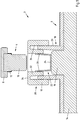
- Fig. 1 an exemplary embodiment of a module connector 2 with connecting part 4 and housing part 6 not connected to one another is shown in a schematic representation.
- connection part 4 has an elongated BusBar conductor 8 which is connected to a contact bolt 10 in a materially bonded manner, in particular by means of an ultrasonic weld seam.
- the contact bolt 10 is cylindrical and has a circumferential, flange-like projection 12 on its side facing the busbar conductor 8.
- the connection part 4 is not connected to the housing part 6.
- the housing part 6 accommodates a module 14, in particular a battery cell, the module 14 having an essentially cylindrical bulge 16.
- the cylindrical bulge 16 is surrounded by a cylindrical, shaft-like projection 18.
- the projection 18 has an external thread 20 on at least part of its outer jacket surface. It can be seen that the wall thickness of the projection 18 decreases in the direction of the module 14 in that the inner lateral surface of the projection 18 tapers in a wedge-like manner.
- a contact socket 22 is materially connected to the end face of the bulge 16.
- the contact socket 22 has a contact plate 24 and contact lamellas 26 shifted cylindrically from the contact plate 24 at an angle of 70 ° to 90 °.
- a connecting part 28 is connected to the projection 18.
- the connecting part 28 is designed in the shape of a nut and has an outside, cylindrical area 30 and an inside, cylindrical area 32.
- the connecting part 28 is screwed to the projection 18 by means of a thread 34 arranged on the inner circumferential surface of the outside region 30.
- the two cylindrical areas 30 and 32 are by means of a on one end face of the Connecting part arranged, annular web 36 connected to one another. Starting from the web 36, the wall thickness of the inner, cylindrical area 32 tapers.
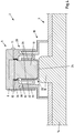
- Fig. 2 is that in Fig. 1 Shown embodiment of the module connector 2 with interconnected connecting part 4 and housing part 6 shown in a schematic representation. It is preferred that the connection part 4 is first plugged into the contact socket 22 of the housing part 6 by means of the contact bolt 10. By means of a screw connection of the connecting part 28, the space in the transverse direction to the contact blades 26 can now be reduced through the wedge-like configuration of the inside, cylindrical area 32 and the inner circumferential surface of the projection 18, whereby the contact forces exerted by the connecting part 28 on the contact blades 26 of Contact socket 22 are exercised, are increased.
- connection lamellas 26 lie over their entire surface and essentially completely encompassing the contact bolt 10 to produce a form-fitting and non-positive connection between the contact socket 22 and the contact bolt 10.
- a process-reliable connection between the connection part 4 and the housing part 6 by means of the connection part 28 can be ensured by means of the screw connection.
- FIG. 3 Another exemplary embodiment of a module connector 2 with connecting part 4 and housing part 6 that are not connected to one another is shown in a schematic representation.
- the connection part 4 is essentially identical to that in FIG Fig. 1 and 2 connecting part 4 shown. It also has a connecting means 11 with which the connecting part 4 can be latched to the connecting part 28.
- the projection 18 of the housing part 6 is different from that in the Fig. 1 and 2 Projection 18 is stepped in cross-section. The end face of the projection 18 is likewise beveled inwards, as a result of which the connection of the connecting part 28 to the projection 18 is simplified.
- the design of the connecting part 28 differs significantly.
- the connecting part 28 likewise has an outside, cylindrical area 30 and an inside, cylindrical area 32, which are connected to one another by means of an annular web 36.
- the inside, cylindrical area 32 is formed as a resilient element 32 in the form of a spring ring.
- the resilient element 32 has a substantially U-shaped cross section.
- a circumferential, annular flange 38 is also formed on the inside of the transition between resilient element 32 and web 36.
- connection part 28 is pushed onto the projection 18, as a result of which inadvertent contact with the contact socket 22 can be prevented.
- connection part 4 latches with the connection part 28 by means of the connecting means 11 and the projection 12 comes to rest on a circumferential collar 13 of the connection part 28, so that the connection part 4 and the connection part 28 continue as a unit into the Housing part 6 are inserted.
- the connecting part 4 and the connecting part 28 are increasingly inserted into the housing part 6, the increasing wall thickness of the projection 18 in the direction of the housing part 6 exerts increasing contact forces on the contact lamellae 26 of the contact socket 22 by pressing the resilient element 32 against the contact lamellae.
- connection part 4 and connection part 28 latches with housing part 6. Such a state is shown in FIG Fig. 4 shown.
- FIG. 5 Another exemplary embodiment of a module connector 2 with connecting part 4 and housing part 6 that are not connected to one another is shown in a schematic representation. This in Fig. 5 The embodiment shown differs from that in FIG Fig. 3 and 4th Embodiments shown that Connecting part 28 and connecting part 4 are formed in one piece. Connecting part 28 and connecting part 4 can, for example, already be manufactured from the same material or are connected to one another during the manufacturing process, for example in a materially bonded manner.
- Fig. 6 shows a schematic representation of an embodiment of a connection part 4 having a BusBar conductor 8, the BusBar conductor 8 having two contact bolts 10, which are materially connected to the BusBar conductor 8 by means of a weld seam 40, in particular by means of an ultrasonic weld seam. It can be seen that the BusBar conductor 8 has a multilayer design.
- Fig. 7 shows a schematic plan view of a contact socket 22 before the forming process. It can be seen that the contact blades 26 extend essentially radially from the contact plate 24.
- the contact socket 22 shown can be produced from sheet metal or sheet metal strip, for example, by means of a stamping process. After the punching process, the contact lamellas 26 are switched over to the contact plate at an angle of 70 ° to 90 °, in particular at an angle of essentially 80 °, by means of a forming process.
- the contact plate 24 can be connected to the module 14 by means of a joining process, in particular by means of a welding process.
Landscapes
- Chemical & Material Sciences (AREA)
- Chemical Kinetics & Catalysis (AREA)
- Electrochemistry (AREA)
- General Chemical & Material Sciences (AREA)
- Connector Housings Or Holding Contact Members (AREA)
- Connection Of Batteries Or Terminals (AREA)
Applications Claiming Priority (1)
| Application Number | Priority Date | Filing Date | Title |
|---|---|---|---|
| DE102019129805.9A DE102019129805B3 (de) | 2019-11-05 | 2019-11-05 | Modulverbinder |
Publications (1)
| Publication Number | Publication Date |
|---|---|
| EP3819981A1 true EP3819981A1 (fr) | 2021-05-12 |
Family
ID=72473448
Family Applications (1)
| Application Number | Title | Priority Date | Filing Date |
|---|---|---|---|
| EP20195695.0A Pending EP3819981A1 (fr) | 2019-11-05 | 2020-09-11 | Raccord de module ainsi que procédé de raccordement de modules |
Country Status (2)
| Country | Link |
|---|---|
| EP (1) | EP3819981A1 (fr) |
| DE (1) | DE102019129805B3 (fr) |
Cited By (2)
| Publication number | Priority date | Publication date | Assignee | Title |
|---|---|---|---|---|
| CN113611985A (zh) * | 2021-10-09 | 2021-11-05 | 信承瑞技术有限公司 | 一种新型智能化储能系统 |
| EP4123790A1 (fr) * | 2021-07-23 | 2023-01-25 | A. Raymond et Cie | Connecteur approprié pour maintenir une barre omnibus en contact avec une électrode d'une batterie, système, procédé et ensemble de batteries |
Families Citing this family (2)
| Publication number | Priority date | Publication date | Assignee | Title |
|---|---|---|---|---|
| DE102020129438A1 (de) | 2020-11-09 | 2022-05-12 | Bayerische Motoren Werke Aktiengesellschaft | Energiespeicher sowie Kraftfahrzeug |
| DE102022110496B4 (de) | 2022-04-29 | 2023-12-21 | Tdk Electronics Ag | Schaltvorrichtung |
Citations (5)
| Publication number | Priority date | Publication date | Assignee | Title |
|---|---|---|---|---|
| JP2003092101A (ja) * | 2001-09-18 | 2003-03-28 | Fujikura Ltd | バッテリターミナル |
| EP2871695A1 (fr) * | 2012-07-05 | 2015-05-13 | SK Innovation Co., Ltd. | Bloc batterie |
| EP2882011A1 (fr) * | 2012-08-01 | 2015-06-10 | Kabushiki Kaisha Toshiba, Inc. | Structure de connexion de batterie secondaire, et appareil à batterie secondaire la comprenant |
| DE102016109882A1 (de) * | 2016-05-30 | 2017-11-30 | Rema Lipprandt Gmbh & Co. Kg | Schnell trennbare elektrische Steckverbindung sowie Verfahren zur Kontaktierung eines elektrischen Kontaktelements mit einem elektrischen Leiter |
| US20180175432A1 (en) * | 2016-12-21 | 2018-06-21 | Samsung Electronics Co., Ltd. | Rechargeable battery and battery module including the same |
Family Cites Families (2)
| Publication number | Priority date | Publication date | Assignee | Title |
|---|---|---|---|---|
| US4179545A (en) * | 1978-05-25 | 1979-12-18 | P. R. Mallory & Co. Inc. | Battery with protectively jacketed female terminal |
| US4394059A (en) * | 1981-08-03 | 1983-07-19 | Amp Incorporated | Connector of a type used with dry cell batteries and manufacturing method |
-
2019
- 2019-11-05 DE DE102019129805.9A patent/DE102019129805B3/de active Active
-
2020
- 2020-09-11 EP EP20195695.0A patent/EP3819981A1/fr active Pending
Patent Citations (6)
| Publication number | Priority date | Publication date | Assignee | Title |
|---|---|---|---|---|
| JP2003092101A (ja) * | 2001-09-18 | 2003-03-28 | Fujikura Ltd | バッテリターミナル |
| EP2871695A1 (fr) * | 2012-07-05 | 2015-05-13 | SK Innovation Co., Ltd. | Bloc batterie |
| EP2882011A1 (fr) * | 2012-08-01 | 2015-06-10 | Kabushiki Kaisha Toshiba, Inc. | Structure de connexion de batterie secondaire, et appareil à batterie secondaire la comprenant |
| DE102016109882A1 (de) * | 2016-05-30 | 2017-11-30 | Rema Lipprandt Gmbh & Co. Kg | Schnell trennbare elektrische Steckverbindung sowie Verfahren zur Kontaktierung eines elektrischen Kontaktelements mit einem elektrischen Leiter |
| US20180175432A1 (en) * | 2016-12-21 | 2018-06-21 | Samsung Electronics Co., Ltd. | Rechargeable battery and battery module including the same |
| KR20180072221A (ko) * | 2016-12-21 | 2018-06-29 | 삼성전자주식회사 | 이차 전지 및 이를 포함하는 전지 모듈 |
Cited By (4)
| Publication number | Priority date | Publication date | Assignee | Title |
|---|---|---|---|---|
| EP4123790A1 (fr) * | 2021-07-23 | 2023-01-25 | A. Raymond et Cie | Connecteur approprié pour maintenir une barre omnibus en contact avec une électrode d'une batterie, système, procédé et ensemble de batteries |
| WO2023001688A1 (fr) * | 2021-07-23 | 2023-01-26 | A. Raymond Et Cie | Connecteur approprié pour maintenir une barre omnibus en contact avec une électrode d'une batterie, système et procédé et ensemble batterie |
| CN113611985A (zh) * | 2021-10-09 | 2021-11-05 | 信承瑞技术有限公司 | 一种新型智能化储能系统 |
| CN113611985B (zh) * | 2021-10-09 | 2021-12-03 | 信承瑞技术有限公司 | 一种新型智能化储能系统 |
Also Published As
| Publication number | Publication date |
|---|---|
| DE102019129805B3 (de) | 2021-05-06 |
Similar Documents
| Publication | Publication Date | Title |
|---|---|---|
| DE102019129805B3 (de) | Modulverbinder | |
| EP2441103B1 (fr) | Connecteur d'éléments de batterie | |
| EP2715838B1 (fr) | Connecteur de cellule | |
| DE102017222352A1 (de) | Anschlusscrimpaufbau und steckverbinder mit kabel | |
| WO2016155846A1 (fr) | Bloc-batterie, et procédé de fabrication d'un bloc-batterie | |
| EP2745337B1 (fr) | Barrette pour élément de batterie, module d'éléments de batterie, procédé de production d'une barrette et véhicule automobile | |
| WO2011054586A1 (fr) | Procédé pour relier un pôle de batterie au niveau d'un premier élément de batterie à un pôle de batterie au niveau d'un second élément de batterie, batterie constituée d'éléments de batterie reliés entre eux et système de batteries | |
| EP2541648A1 (fr) | Connecteur de cellules | |
| EP2572396A1 (fr) | Élément de batterie lithium-ion ainsi que procédé pour établir une mise en contact électroconductrice de bornes d'éléments de batterie | |
| EP3206258A1 (fr) | Système de fabrication d'un raccordement électrique, raccordement électrique et son procédé de fabrication | |
| DE102012223766B4 (de) | Energiespeicheranordnung und Verfahren zur Herstellung der Energiespeicheranordnung | |
| DE102015113376A1 (de) | Zinnfusionsverbinden zur robusten integration elektrischer komponenten mit axialen drähten | |
| EP4094326B1 (fr) | Agencement de connexion et procédé de raccordement d'agencement de connexion à un composant | |
| EP2820696B1 (fr) | Batterie comprenant au moins deux éléments et comprenant au moins un élément de liaison | |
| EP2595826B1 (fr) | Dispositif d'alimentation électrique comprenant un boîtier pour accueillir au moins un module accumulateur d'énergie | |
| DE102013208344A1 (de) | Verfahren zum Herstellen einer elektrischen Verbindung zwischen zwei Kontaktstiften, insbesondere zwischen Kontaktstiften von Batteriezellen, und Batterie mit einer solchen elektrischen Verbindung | |
| DE102018201438A1 (de) | Flexibler Zellverbinder | |
| DE102016208589A1 (de) | Elektrodenanordnung einer Batteriezelle, Elektrodenschicht und Batteriezelle sowie Verfahren zu deren Herstellung | |
| DE102021006201A1 (de) | Batteriemodul mit mehreren zylindrischen Batterieeinzelzellen | |
| DE102013217464A1 (de) | Speicherzelle eines elektrischen Energiespeichers mit einem Verbinder | |
| DE102021001981A1 (de) | Verbindungsanordnung eines ersten Kontaktelements an einem zweiten Kontaktelement, insbesondere für ein Kraftfahrzeug, sowie Verfahren zum Herstellen einer solchen Verbindungsanordnung | |
| DE102015207550A1 (de) | Zellverbinder mit Toleranzausgleich | |
| WO2023088818A1 (fr) | Accumulateur d'énergie, procédé de fabrication d'un accumulateur d'énergie et véhicule | |
| DE102011051463A1 (de) | Verfahren zum Herstellen einer Fügeverbindung zwischen einem ersten Bauteil und einem zweiten Bauteil und Baugruppe aus einem ersten Bauteil und einem zweiten Bauteil | |
| DE102020102402A1 (de) | Verfahren zur Herstellung eines Modulverbinders sowie Modulverbinder |
Legal Events
| Date | Code | Title | Description |
|---|---|---|---|
| PUAI | Public reference made under article 153(3) epc to a published international application that has entered the european phase |
Free format text: ORIGINAL CODE: 0009012 |
|
| STAA | Information on the status of an ep patent application or granted ep patent |
Free format text: STATUS: THE APPLICATION HAS BEEN PUBLISHED |
|
| AK | Designated contracting states |
Kind code of ref document: A1 Designated state(s): AL AT BE BG CH CY CZ DE DK EE ES FI FR GB GR HR HU IE IS IT LI LT LU LV MC MK MT NL NO PL PT RO RS SE SI SK SM TR |
|
| STAA | Information on the status of an ep patent application or granted ep patent |
Free format text: STATUS: REQUEST FOR EXAMINATION WAS MADE |
|
| 17P | Request for examination filed |
Effective date: 20211111 |
|
| RBV | Designated contracting states (corrected) |
Designated state(s): AL AT BE BG CH CY CZ DE DK EE ES FI FR GB GR HR HU IE IS IT LI LT LU LV MC MK MT NL NO PL PT RO RS SE SI SK SM TR |
|
| P01 | Opt-out of the competence of the unified patent court (upc) registered |
Effective date: 20230513 |
|
| GRAP | Despatch of communication of intention to grant a patent |
Free format text: ORIGINAL CODE: EPIDOSNIGR1 |
|
| STAA | Information on the status of an ep patent application or granted ep patent |
Free format text: STATUS: GRANT OF PATENT IS INTENDED |
|
| RIC1 | Information provided on ipc code assigned before grant |
Ipc: H01R 4/38 20060101ALI20240729BHEP Ipc: H01M 50/552 20210101ALI20240729BHEP Ipc: H01M 50/514 20210101ALI20240729BHEP Ipc: H01M 50/503 20210101AFI20240729BHEP |
|
| INTG | Intention to grant announced |
Effective date: 20240814 |