EP3819264A1 - Reactor, system and method for the treatment of liquid manure or digestates, especially suitable for the treatment of slurry - Google Patents
Reactor, system and method for the treatment of liquid manure or digestates, especially suitable for the treatment of slurry Download PDFInfo
- Publication number
- EP3819264A1 EP3819264A1 EP19737805.2A EP19737805A EP3819264A1 EP 3819264 A1 EP3819264 A1 EP 3819264A1 EP 19737805 A EP19737805 A EP 19737805A EP 3819264 A1 EP3819264 A1 EP 3819264A1
- Authority
- EP
- European Patent Office
- Prior art keywords
- chamber
- reactor
- liquid
- slurry
- treatment
- Prior art date
- Legal status (The legal status is an assumption and is not a legal conclusion. Google has not performed a legal analysis and makes no representation as to the accuracy of the status listed.)
- Granted
Links
Images

Classifications
-
- C—CHEMISTRY; METALLURGY
- C02—TREATMENT OF WATER, WASTE WATER, SEWAGE, OR SLUDGE
- C02F—TREATMENT OF WATER, WASTE WATER, SEWAGE, OR SLUDGE
- C02F1/00—Treatment of water, waste water, or sewage
- C02F1/24—Treatment of water, waste water, or sewage by flotation
-
- C—CHEMISTRY; METALLURGY
- C02—TREATMENT OF WATER, WASTE WATER, SEWAGE, OR SLUDGE
- C02F—TREATMENT OF WATER, WASTE WATER, SEWAGE, OR SLUDGE
- C02F1/00—Treatment of water, waste water, or sewage
- C02F1/52—Treatment of water, waste water, or sewage by flocculation or precipitation of suspended impurities
- C02F1/5236—Treatment of water, waste water, or sewage by flocculation or precipitation of suspended impurities using inorganic agents
- C02F1/5245—Treatment of water, waste water, or sewage by flocculation or precipitation of suspended impurities using inorganic agents using basic salts, e.g. of aluminium and iron
-
- C—CHEMISTRY; METALLURGY
- C02—TREATMENT OF WATER, WASTE WATER, SEWAGE, OR SLUDGE
- C02F—TREATMENT OF WATER, WASTE WATER, SEWAGE, OR SLUDGE
- C02F1/00—Treatment of water, waste water, or sewage
- C02F1/52—Treatment of water, waste water, or sewage by flocculation or precipitation of suspended impurities
-
- C—CHEMISTRY; METALLURGY
- C02—TREATMENT OF WATER, WASTE WATER, SEWAGE, OR SLUDGE
- C02F—TREATMENT OF WATER, WASTE WATER, SEWAGE, OR SLUDGE
- C02F1/00—Treatment of water, waste water, or sewage
- C02F1/66—Treatment of water, waste water, or sewage by neutralisation; pH adjustment
-
- C—CHEMISTRY; METALLURGY
- C02—TREATMENT OF WATER, WASTE WATER, SEWAGE, OR SLUDGE
- C02F—TREATMENT OF WATER, WASTE WATER, SEWAGE, OR SLUDGE
- C02F2103/00—Nature of the water, waste water, sewage or sludge to be treated
- C02F2103/20—Nature of the water, waste water, sewage or sludge to be treated from animal husbandry
-
- C—CHEMISTRY; METALLURGY
- C02—TREATMENT OF WATER, WASTE WATER, SEWAGE, OR SLUDGE
- C02F—TREATMENT OF WATER, WASTE WATER, SEWAGE, OR SLUDGE
- C02F2209/00—Controlling or monitoring parameters in water treatment
- C02F2209/06—Controlling or monitoring parameters in water treatment pH
-
- C—CHEMISTRY; METALLURGY
- C02—TREATMENT OF WATER, WASTE WATER, SEWAGE, OR SLUDGE
- C02F—TREATMENT OF WATER, WASTE WATER, SEWAGE, OR SLUDGE
- C02F2303/00—Specific treatment goals
- C02F2303/24—Separation of coarse particles, e.g. by using sieves or screens
-
- Y—GENERAL TAGGING OF NEW TECHNOLOGICAL DEVELOPMENTS; GENERAL TAGGING OF CROSS-SECTIONAL TECHNOLOGIES SPANNING OVER SEVERAL SECTIONS OF THE IPC; TECHNICAL SUBJECTS COVERED BY FORMER USPC CROSS-REFERENCE ART COLLECTIONS [XRACs] AND DIGESTS
- Y02—TECHNOLOGIES OR APPLICATIONS FOR MITIGATION OR ADAPTATION AGAINST CLIMATE CHANGE
- Y02A—TECHNOLOGIES FOR ADAPTATION TO CLIMATE CHANGE
- Y02A40/00—Adaptation technologies in agriculture, forestry, livestock or agroalimentary production
- Y02A40/10—Adaptation technologies in agriculture, forestry, livestock or agroalimentary production in agriculture
- Y02A40/20—Fertilizers of biological origin, e.g. guano or fertilizers made from animal corpses
-
- Y—GENERAL TAGGING OF NEW TECHNOLOGICAL DEVELOPMENTS; GENERAL TAGGING OF CROSS-SECTIONAL TECHNOLOGIES SPANNING OVER SEVERAL SECTIONS OF THE IPC; TECHNICAL SUBJECTS COVERED BY FORMER USPC CROSS-REFERENCE ART COLLECTIONS [XRACs] AND DIGESTS
- Y02—TECHNOLOGIES OR APPLICATIONS FOR MITIGATION OR ADAPTATION AGAINST CLIMATE CHANGE
- Y02P—CLIMATE CHANGE MITIGATION TECHNOLOGIES IN THE PRODUCTION OR PROCESSING OF GOODS
- Y02P20/00—Technologies relating to chemical industry
- Y02P20/141—Feedstock
- Y02P20/145—Feedstock the feedstock being materials of biological origin
Definitions
- the invention belongs to the field of treatment of farm manures and related waste, which pays special attention to how to prepare a liquid fraction of the same for reuse.
- Liquid manures refers to the liquid formed by animal urine and what leaks from manure.
- slurry consists of the mixture of solid and liquid waste, that is to say, of faeces and urine, normally mixed with the water used for cleaning the barns.
- Liquid manures have traditionally been used as fertilizer elements, being recycling to convert them into an organic fertilizer for cultivated land, with the consequent saving of chemical fertilizers and in costs.
- ammonia When the ammonia dissolves in water, an amount of the same is converted into ammonium ions.
- ammonium ion it is known that the degree to which the ammonium ion is converted into ammonia depends mainly on the pH of the solution and on the temperature. If the pH is low, more ammonia molecules are converted into ammonium ions (non-evaporative). If the pH is high, the hydroxide ion extracts a proton from the ammonium ion, generating ammonia (evaporative).
- this coagulation treatment may be followed by a flocculation treatment, in this case without controlling the pH value.
- a mineral coagulant is proposed as a coagulant, which can be chosen from the group consisting of ferrous chloride, ferric chloride, ferrous sulphate, ferric sulphate, ferric chlorosulphate, aluminium sulphates or basic aluminium chlorosulphates; or an organic agent, listing a neutral polyelectrolyte 0 as candidate, and very preferably, cationic. At least one anionic polyelectrolyte is preferably mentioned as the flocculant.
- the coagulation and flocculation treatment is carried out in different apparatuses, such that after the coagulation treatment in the coagulator apparatus the medium to be treated is led to the apparatus used for flocculation.
- the flocculant is injected into the stream of medium being treated between the two apparatuses.
- a liquid/solid separation operation is carried out by a float or hydrocyclone (when treating animal excrements).
- the proposal is exemplified, by treating liquid pig excrements, with a float device from which a separate sludge is obtained with a 5.28% dry extract at 105°C.
- a solution that is capable of extracting a separated sludge with a higher value of dry extract is of interest.
- An object of the present invention is also a more compact and versatile solution, which can adapt to different livestock farms quickly and safely and requires less space than the known solutions.
- the solution that is pursued can also not renounce other basic objectives, such as the suppression of odours, essentially caused by volatile organic materials and bound elements (such as H2S and NH3); and the removal of the phosphate from the recovered liquid fraction.
- other basic objectives such as the suppression of odours, essentially caused by volatile organic materials and bound elements (such as H2S and NH3); and the removal of the phosphate from the recovered liquid fraction.
- a compact reactor for the treatment of liquid manure or digestates is disclosed, which is especially suitable for the treatment of a liquid part of slurry, comprising a closed container with at least three chambers for subjecting the manure to three consecutive treatment stages, and in particular
- the reactor thus provides a compact solution that requires less space than conventional installations while being more versatile.
- the reactor is adapted to control the pH of the medium under treatment not only in the first but also in the second chamber, which enables an excess dosage of flocculant to be avoided, as is the case in the known methods that do not implement any control in this regard, as is the case with the method described in ES 2147975 .
- the second chamber also enables the adjustment of the necessary dose of flocculant and knowing with certainty the pH of the medium at the outlet, both of the solid part and the liquid part.
- the arrangement in chambers, which are hydraulically connected, and the natural overflow passage between the first and the second chamber prevents the medium from being subjected to overpressures that may impair the stability of the flocs, as is the case when having different apparatuses to subject the medium to a coagulation treatment and to a flocculation treatment, which entails the use of pumping groups for the transfer of the medium between the different apparatuses.
- the first chamber is equipped with at least first stirring means; an upper outlet, intended to enable the evacuation of gases; a first pH probe; and first dosing means for the combined or separate dosing of a coagulant, an acidifier and an anti-foaming agent in the quantity and proportions required to maintain the pH level between 5 and 6.5.
- the coagulant comprises at least one of aluminium polyhydroxychlorosulphate (PACS) or aluminium hydroxychloride (PACI).
- PHS aluminium polyhydroxychlorosulphate
- PACI aluminium hydroxychloride
- the second chamber is equipped with at least second stirring means; a second pH probe; and second dosing means for the dosing of flocculant in the quantity and proportions required to maintain the pH level below 6.8.
- the flocculant is a solid mixture of cationic flocculant, with a medium or high cationicity and high molecular weight with a smaller part of an organic acid.
- the first and second dosing means for the dosing of coagulant and flocculant, respectively, as well as the acidifier and the anti-foaming agent can comprise continuous or interval dosing pumps, according to an associated control unit depending on the instantaneous pH values of the medium measured in said first and second chambers and the target pH value for each chamber.
- the volume ratio V1 of the first chamber and V2 of the second chamber fulfils the ratio V1 ⁇ V2; and the first and second stirring means comprising first and second propeller stirrers or blades with a vertical axis, the ratio of the rotation speeds R1 of the first propeller stirrer or blades and R2 of the second propeller stirrer or blades fulfils the ratio R1>R2.
- the stirring in the first chamber will be faster than that of the second chamber.
- the third chamber is equipped with an overflow device, with communication between the compartment to settle the flocs and the sieve device, which is adjustable in height in order to be able to control the level of the free surface of the medium under treatment in the first, second and third chambers due to the effect of communicating vessels.
- the surfaces of the container in contact with the liquid manure under treatment can be made of polypropylene.
- the container may comprise two adjoining chambers for preparing in situ the flocculant to be used in the second chamber.
- an installation for the treatment of slurry comprising a solid-liquid separator to obtain a solid fraction and a liquid fraction of the slurry; and a reactor according to the invention, the receiving inlet of which is connected to the separator for feeding the liquid fraction of the slurry to the reactor, the separator being optionally arranged above the reactor.
- a method for the treatment of slurry comprising the steps of a) mechanically separating a liquid fraction (L) from a solid fraction (S) of the slurry, obtaining a solid fraction (S) with 15-30% dryness; and b) subjecting the obtained liquid fraction to a physical-chemical process in an essentially closed and sequential environment, firstly a coagulation process, then a flocculation process and finally a filtering process taking the appropriate measures so that the liquid and solid parts remain at all times in acid form in order to, among other factors, favour the presence of ammonium ion and prevent ammonia emissions.
- the reactor of the invention is especially suitable for carrying out said step b).
- step b) comprises the operations of b3) subjecting the obtained liquid fraction to a chemical coagulation process under vigourous stirring and controlled conditions of the pH level between 5 and 6.5; b4) subjecting the coagulate resulting from operation b3) to a chemical flocculation process under moderate stirring and controlled conditions of the pH level below 6.8; and b5) settling the flocs with suspended solids obtained from operation b4) and pouring them, by overflow, into a sieve device, preferably of the curved type, thus obtaining a recovered liquid fraction (Lr) that passes through the sieve device and a recovered solid fraction (Sr) that slides through the sieve device.
- a sieve device preferably of the curved type
- the solid fraction (Sr) recovered in operation b5) is dried in drying basins and then mixed with the solid fraction (S) of the slurry obtained in operation a), obtaining a final solid that is capable of being dried, intended for composting or to be used as fertilizer.
- the pH value of the material or medium in the coagulation process is monitored and a coagulant is dosed combined or separately, an acidifier and an anti-foaming agent in the quantity and proportions required to maintain the pH level between 5 and 6.5.
- the pH value of the material or medium in the flocculation process is monitored and a flocculant which is a solid mixture of cationic flocculant is dosed, with a medium or high cationicity and high molecular weight with a smaller part of an organic acid.
- Fig. 1 schematically shows an installation exemplifying the invention. The parts of the same are not represented to scale and the purpose of the diagram is only to provide the reader with the explanations that follow.
- Fig. 1 the installation of Fig. 1 comprises a basin 30 of farm slurry 33, preferably of the stirred type, from which and conventionally by means of a pumping group 31, the slurry to be treated is driven to a solid/liquid separator 32.
- This separator 32 can be, for example, a TECNAPUR® model TP-01 separator, with a treatment flow of 5m 3 /h.
- the obtained solid (S), with approximately 25% dryness, can be used to throw onto the land, can be composted or can be used for other uses, in the present example prior to mixing with a recovered solid (Sr) obtained at a later stage, as explained later.
- Table 1 Example and characterisation of the solid-liquid separation stage with TECNAPUR model TP-01 separator.
- the resulting liquid fraction (L) (comprising 58.8% of dry matter of the initial slurry) is led directly and without deposits to a compact reactor 100, the details of which will be explained below, and a recovered liquid fraction (Lr) and the recovered solid fraction (Sr) mentioned above will be obtained from this liquid fraction (L).
- ammonia is 99.99% non-evaporative and atmospheric emissions of greenhouse gases (GHG) CH4, N2O, CO2, NOx, and the smells are eliminated, in addition to reaching a very significant reduction of nitrogen and phosphorus of the liquid part.
- GFG greenhouse gases
- the contribution of the reactor 100 to achieve this balance is significant.
- the liquid fraction (L) obtained in the solid/liquid separator 32 is subjected to a physical-chemical process in an essentially closed and sequential environment, firstly a coagulation process, then a flocculation process and finally a filtering process taking the appropriate measures so that the liquid and solid parts remain at all times in acid form in order to, among other factors, favour the presence of ammonium ion and prevent ammonia emissions.
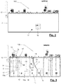
- This reactor 100 illustrated in Figs. 2 and 3 , comprises a container 2 constructed of materials resistant to the chemical reactions that occur inside the same.
- the reactor 100 is made of double-walled polypropylene and stainless steel AISI 316.
- the container 2 has internal divisions, that is, it is compartmentalised, three chambers being determined to subject the liquid fraction (L) coming from the solid/liquid separator 32 to the three consecutive treatment stages.
- These three chambers are the following:
- the method that is carried out in the installation is as follows:
- the liquid fraction (L) of the slurry to be treated is obtained by means of the solid/liquid separator 32.
- Said separator 32 is arranged superposed to the reactor 100, being able to feed said liquid fraction (L) to the reactor 100 by means of gravity, entering the first chamber 3 through the receiving inlet 10, the discharge mouth of which is immersed in the medium under treatment.
- This first chamber 3 is equipped with first stirring means 12 with a set of blades 12a and with first dosing means 15 for the combined or separate dosing of a coagulant, an acidifier and an anti-foaming agent in the quantity and proportions required to maintain the pH level of the medium between 5 and 6.5.
- first stirring means 12 with a set of blades 12a and with first dosing means 15 for the combined or separate dosing of a coagulant, an acidifier and an anti-foaming agent in the quantity and proportions required to maintain the pH level of the medium between 5 and 6.5.
- first dosing means 15 for the combined or separate dosing of a coagulant, an acidifier and an anti-foaming agent in the quantity and proportions required to maintain the pH level of the medium between 5 and 6.5.
- the container 2 is essentially a closed container and the medium under treatment is not in contact with the atmosphere, the first chamber 3 has an upper outlet 13 intended to enable the evacuation of gases.
- first dosing means 15 is schematic in Fig. 3 .
- the dosage by means of separate conduits or injectors is of interest, as well as being able to locate the supply point in an area near the mouth of the receiving inlet.
- the first chamber 3 has a first pH probe 14 that is capable of monitoring the pH of the medium under treatment, continuously or at intervals.
- the pH value is sent to a control unit, which is not shown, that seeks the combined or separate dosing of the coagulant, the acidifier and the anti-foaming agent in the quantities and proportions required to maintain said pH level between 5 and 6.5.
- the control unit will regulate the operation of both impeller pumps for these products.
- the coagulant comprises at least one of aluminium polyhydroxychlorosulphate (PACS) or aluminium hydroxychloride (PACI).
- PPS aluminium polyhydroxychlorosulphate
- PACI aluminium hydroxychloride
- These coagulants have different solid bases in the hydrolytic reactions with respect to the conventional coagulants and in practice it has been revealed that the PAC flocs unpredictably tend to be groups of small spheres and chain type structures with a size less than 25 mm, while the flocs obtained with conventional coagulants, of the aluminium sulphate type, are usually spongy and porous structures with a size of 25 to 100 mm. This difference causes the PACs to produce a lower turbidity in suspension than aluminium sulphate.
- PACs are more efficient than aluminium sulphate, given their greater ability to remove suspended solids, a lower dose is required: depending on the type of slurry, it can substitute 1.5 to 2.0 parts of grade A aluminium sulphate and 3.5 to 3.9 parts of grade B aluminium sulphate.
- this is an inorganic salt of multinuclear aluminium (PAC) that is capable of forming, more quickly and perfectly, flocs with higher sedimentation speed and clarifying power, achieving higher turbidity removals compared to other mononuclear aluminium salts such as aluminium sulphate.
- PAC multinuclear aluminium
- Aluminium hydroxychloride is commercially available as a slightly viscous light amber liquid, sometimes opalescent and having an astringent sweet flavour. It has the advantage that it is easy to handle and dose without leaving undesirable insoluble residues, unlike conventional granulated coagulants that must be dissolved and in many cases leave residues that damage the dosing equipment.
- aluminium hydroxychloride improves the rate of floc formation; enables a higher sedimentation rate, protects dosing equipment; and requires shorter mixing times for coagulation.
- aluminium hydroxychloride tends to quickly acidify the medium depending on the dose, which results in this method of interest when the pH of the medium is to be maintained in acid values.
- the acidifier can be selected from sulphuric or hydrochloric acid.
- the first chamber 3 of the reactor 100 is hydraulically connected to the second chamber 4 by means of a sewage pipe 23 arranged in the upper portion of the first chamber 3 but preferably at a level below the free surface of the medium in the first chamber 4.
- the sewage pipe 23 is bent and opens into the second chamber 4 at an intermediate level.
- the sewage pipe 23 can have a vertical branch that communicates with the outside of the container 2.
- the second chamber 4 is equipped with second stirring means 16 with a set of blades 16a and with second dosing means 18 for dosing the flocculant in the quantity and proportions required to maintain the pH level below 6.8.
- the supply of flocculant is carried out inside the vertical branch of the sewage pipe 23 with the supply point being located at or below the horizontal section of the sewage pipe 23.
- the second chamber 4 has a second pH probe 17 that is capable of monitoring the pH of the medium under treatment, continuously or at intervals.
- the pH value is sent to the aforementioned control unit, or to another associated control unit, which ensures the dosage of the flocculant in the quantity required to maintain said pH level below 6.8.
- this control unit will regulate the operation of an impeller pump for the flocculant product.
- the flocculant is a solid mixture of cationic flocculant, with a medium or high cationicity and high molecular weight with a smaller part of an organic acid.
- Table 4 characterises flocculants with these characteristics.
- the invention consequently envisages the use, in combination with the selected flocculant, less than 10% in proportion of an acid, as an organic acid buffer.
- the capacity of the first chamber 3 is 600 I and the capacity of the second chamber 4 is 800 I.
- the stirring carried out in the first chamber 3 is fast stirring and the stirring carried out in the second chamber 4 is slow stirring.
- the speed of rotation of the vanes 12a and 16a can be regulated to control the speed of rotation at optimum values.
- fast stirring is considered to be that which is obtained at speeds of between 700 and 1500 rpm; and slow stirring to be that which is obtained at speeds of rotation below 300 rpm.
- Said second chamber 4 is in hydraulic communication with a third chamber 5 by means of a passage 24 arranged at an intermediate level which opens into a compartment for settling 6 the flocs formed in the third chamber 5 and equipped with an overflow device 19 through which the flocs are poured onto the sieve device 7.
- the overflow device 19 is preferably adjustable in height in order to control the level of the free surface of the medium under treatment in the first, second and third chambers 3, 4 and 5 due to the effect of communicating vessels.
- the compartment to settle 6 the flocs, or plenum chamber, is a small volume and is not stirred, contributing to a better grouping and compaction of the flocs before the separation that takes place in the sieve device 7.
- the flocs are poured naturally and continuously onto the sieve device 7 and separated by rolling the solid towards the lower portion of the sieve device 7, which contributes to drying the same in the path without destroying it.
- the solid that reaches the lower portion of the sieve device will constitute the recovered solid fraction (Sr) that is continuously removed by the collecting means 9 at a maximum of 2000 kg/h.
- the liquid part that passes through the sieve device 7 will constitute the recovered liquid fraction (Lr) and is devoid of suspended solids, having colour reduction to a light orange shade.
- This recovered liquid fraction (Lr) is continuously extracted from the reactor 100 and can be subjected to subsequent treatments and/or sent to a basin.
- the reactor 100 is preferably equipped with an automatic cleaning system 7a of the sieve device 7.
- This automatic cleaning system 7a (illustrated schematically in Fig. 3 ) can consist of a series of nozzles suitable for projecting jets of liquid onto the sieve device 7.
- the energy consumption associated with the pumping group 31, the separator 32 and the physical-chemical system inside the reactor 100 is less than 5 KW/h for a maximum flow of 15 m 3 /hour, which represents significant energy savings in comparison to other well-known methods, especially with respect to those that use the electrocoagulation technique or that use centrifugation devices.
- the reactor 100 that exemplifies the invention comprises first and second contiguous added chambers 21 and 22, to continuously produce in situ the flocculant used in the flocculation stage that is carried out in the second chamber 4.
- the first added chamber 21 incorporates thereon a receiving hopper with a capacity of about 60 litres, wherein the cationic flocculant in powder form of the type parameterised in Table 4 is added.
- This powdered flocculant is dosed with a heated auger conveyor actuated by a gear motor with speed regulation capability, in order to control the quantity of powdered flocculant that is to be supplied to the first added chamber 21.
- water is supplied from the network, at a controlled rate of approximately 1200 litres/hour with a rotameter, and it is mixed with the powdered flocculant by stirring the medium by means of a blade stirrer rotating at a rate of about 200 rpm.
- the stirred medium passes through communicating vessels into the second added chamber 22 and is also subjected to stirring, where the mixture has just matured to be dosed into the second chamber 4.
- the use of a pulse counter flow meter before the inlet of the rotameter is also envisaged so that it is possible to dose an emulsion flocculant (a highly concentrated liquid mixture, but more expensive in economic terms) instead of powder.
- the pulse counter would be connected to a pulse pump for dosing the emulsion flocculant to be introduced into the first added chamber 21 from a receptacle or container.
Landscapes
- Chemical & Material Sciences (AREA)
- Life Sciences & Earth Sciences (AREA)
- Hydrology & Water Resources (AREA)
- Engineering & Computer Science (AREA)
- Environmental & Geological Engineering (AREA)
- Water Supply & Treatment (AREA)
- Organic Chemistry (AREA)
- Inorganic Chemistry (AREA)
- Separation Of Suspended Particles By Flocculating Agents (AREA)
- Treatment Of Sludge (AREA)
Abstract
Description
- The invention belongs to the field of treatment of farm manures and related waste, which pays special attention to how to prepare a liquid fraction of the same for reuse.
- Liquid manures (slurry) refers to the liquid formed by animal urine and what leaks from manure. In livestock farms, for example, pig farms, in practice, slurry consists of the mixture of solid and liquid waste, that is to say, of faeces and urine, normally mixed with the water used for cleaning the barns.
- Liquid manures have traditionally been used as fertilizer elements, being recycling to convert them into an organic fertilizer for cultivated land, with the consequent saving of chemical fertilizers and in costs.
- Slurries have basic pHs which favours the emission of ammonia and other greenhouse gases into the atmosphere, due to the fact that uninterrupted product decomposition reactions take place in these mixing conditions.
- When the ammonia dissolves in water, an amount of the same is converted into ammonium ions. The balance between ammonia and ammonium ions is expressed as follows: NH4+ +OH- = NH3 + H2O.
- It is known that the degree to which the ammonium ion is converted into ammonia depends mainly on the pH of the solution and on the temperature. If the pH is low, more ammonia molecules are converted into ammonium ions (non-evaporative). If the pH is high, the hydroxide ion extracts a proton from the ammonium ion, generating ammonia (evaporative).
- Taking advantage of this principle, different slurry treatment proposals that either favour the evaporation of ammonia for the recovery thereof, which is the case of the extraction and thermal dehydration processes of volatile organic matter and the nitrogenous ammonia compounds, or that try to keep it in the form of an ammonium ion, for example, the nitrification/denitrification biological processes that produce a biological sludge that contains most of the phosphates, are currently known. Nevertheless, the presence of solid components in the slurry and the necessary energy and space contribution for the implementation of some of these proposals mean that they are not efficient.
- Among the methods that seek to avoid the evaporation of ammonia, for example, the one described in patent document
ES 2147975 - Optionally, this coagulation treatment may be followed by a flocculation treatment, in this case without controlling the pH value. A mineral coagulant is proposed as a coagulant, which can be chosen from the group consisting of ferrous chloride, ferric chloride, ferrous sulphate, ferric sulphate, ferric chlorosulphate, aluminium sulphates or basic aluminium chlorosulphates; or an organic agent, listing a neutral polyelectrolyte 0 as candidate, and very preferably, cationic. At least one anionic polyelectrolyte is preferably mentioned as the flocculant.
- In document
ES 2147975 - Next, in a subsequent step carried out in another apparatus, a liquid/solid separation operation is carried out by a float or hydrocyclone (when treating animal excrements). The proposal is exemplified, by treating liquid pig excrements, with a float device from which a separate sludge is obtained with a 5.28% dry extract at 105°C.
- A solution that is capable of extracting a separated sludge with a higher value of dry extract is of interest.
- Likewise, in order to implement the proposal according to
ES 2147975 - An object of the present invention is also a more compact and versatile solution, which can adapt to different livestock farms quickly and safely and requires less space than the known solutions.
- The solution that is pursued can also not renounce other basic objectives, such as the suppression of odours, essentially caused by volatile organic materials and bound elements (such as H2S and NH3); and the removal of the phosphate from the recovered liquid fraction.
- In order to solve the drawbacks described above, a compact reactor for the treatment of liquid manure or digestates is disclosed, which is especially suitable for the treatment of a liquid part of slurry, comprising a closed container with at least three chambers for subjecting the manure to three consecutive treatment stages, and in particular
- a first chamber with a receiving inlet for receiving the liquid manure to be treated, prepared to subject liquid manure to a chemical coagulation process under controlled conditions of the pH level between 5 and 6.5;
- a second chamber in communication with the first chamber, prepared to subject a coagulated overflow of the first chamber to a chemical flocculation process under controlled conditions of the pH level below 6.8; and
- a third chamber in communication with the second chamber and in which a compartment is formed for settling the flocs with suspended solids formed in the second chamber; and a sieve device, preferably curved with a horizontal triangular mesh, over which the content of the compartment for settling the flocs overflows for the separation thereof, the third chamber further comprising an outlet for the recovered liquid fraction (Lr) that passes through the sieve device and collecting means for collecting the recovered solid fraction (Sr) which slides through the sieve device, in the curved example with a horizontal triangular mesh, forming a characteristic solid of the system in the form of small cylinders, in connection with the outside of the container.
- The reactor thus provides a compact solution that requires less space than conventional installations while being more versatile.
- Note that the reactor is adapted to control the pH of the medium under treatment not only in the first but also in the second chamber, which enables an excess dosage of flocculant to be avoided, as is the case in the known methods that do not implement any control in this regard, as is the case with the method described in
ES 2147975 - The arrangement in chambers, which are hydraulically connected, and the natural overflow passage between the first and the second chamber prevents the medium from being subjected to overpressures that may impair the stability of the flocs, as is the case when having different apparatuses to subject the medium to a coagulation treatment and to a flocculation treatment, which entails the use of pumping groups for the transfer of the medium between the different apparatuses.
- In a variant of the invention, the first chamber is equipped with at least first stirring means; an upper outlet, intended to enable the evacuation of gases; a first pH probe; and first dosing means for the combined or separate dosing of a coagulant, an acidifier and an anti-foaming agent in the quantity and proportions required to maintain the pH level between 5 and 6.5.
- Preferably, the coagulant comprises at least one of aluminium polyhydroxychlorosulphate (PACS) or aluminium hydroxychloride (PACI).
- In a variant of the invention, the second chamber is equipped with at least second stirring means; a second pH probe; and second dosing means for the dosing of flocculant in the quantity and proportions required to maintain the pH level below 6.8.
- Preferably, the flocculant is a solid mixture of cationic flocculant, with a medium or high cationicity and high molecular weight with a smaller part of an organic acid.
- As explained later, the first and second dosing means for the dosing of coagulant and flocculant, respectively, as well as the acidifier and the anti-foaming agent can comprise continuous or interval dosing pumps, according to an associated control unit depending on the instantaneous pH values of the medium measured in said first and second chambers and the target pH value for each chamber.
- According to one embodiment, the volume ratio V1 of the first chamber and V2 of the second chamber fulfils the ratio V1<V2; and the first and second stirring means comprising first and second propeller stirrers or blades with a vertical axis, the ratio of the rotation speeds R1 of the first propeller stirrer or blades and R2 of the second propeller stirrer or blades fulfils the ratio R1>R2. In practice, the stirring in the first chamber will be faster than that of the second chamber.
- In a variant of interest, which helps to make the reactor compact, the third chamber is equipped with an overflow device, with communication between the compartment to settle the flocs and the sieve device, which is adjustable in height in order to be able to control the level of the free surface of the medium under treatment in the first, second and third chambers due to the effect of communicating vessels.
- The surfaces of the container in contact with the liquid manure under treatment can be made of polypropylene.
- Optionally, the container may comprise two adjoining chambers for preparing in situ the flocculant to be used in the second chamber.
- According to another aspect of the invention, an installation for the treatment of slurry is disclosed, comprising a solid-liquid separator to obtain a solid fraction and a liquid fraction of the slurry; and a reactor according to the invention, the receiving inlet of which is connected to the separator for feeding the liquid fraction of the slurry to the reactor, the separator being optionally arranged above the reactor.
- According to another aspect of the invention, a method for the treatment of slurry is disclosed comprising the steps of a) mechanically separating a liquid fraction (L) from a solid fraction (S) of the slurry, obtaining a solid fraction (S) with 15-30% dryness; and b) subjecting the obtained liquid fraction to a physical-chemical process in an essentially closed and sequential environment, firstly a coagulation process, then a flocculation process and finally a filtering process taking the appropriate measures so that the liquid and solid parts remain at all times in acid form in order to, among other factors, favour the presence of ammonium ion and prevent ammonia emissions.
- The reactor of the invention is especially suitable for carrying out said step b).
- In a form that is of interest, step b) comprises the operations of b3) subjecting the obtained liquid fraction to a chemical coagulation process under vigourous stirring and controlled conditions of the pH level between 5 and 6.5; b4) subjecting the coagulate resulting from operation b3) to a chemical flocculation process under moderate stirring and controlled conditions of the pH level below 6.8; and b5) settling the flocs with suspended solids obtained from operation b4) and pouring them, by overflow, into a sieve device, preferably of the curved type, thus obtaining a recovered liquid fraction (Lr) that passes through the sieve device and a recovered solid fraction (Sr) that slides through the sieve device.
- Preferably, the solid fraction (Sr) recovered in operation b5) is dried in drying basins and then mixed with the solid fraction (S) of the slurry obtained in operation a), obtaining a final solid that is capable of being dried, intended for composting or to be used as fertilizer.
- According to a preferred embodiment of the method, in operation b3) the pH value of the material or medium in the coagulation process is monitored and a coagulant is dosed combined or separately, an acidifier and an anti-foaming agent in the quantity and proportions required to maintain the pH level between 5 and 6.5.
- Likewise, also preferably in operation b4), the pH value of the material or medium in the flocculation process is monitored and a flocculant which is a solid mixture of cationic flocculant is dosed, with a medium or high cationicity and high molecular weight with a smaller part of an organic acid.
-
-
Fig. 1 schematically shows an installation for the implementation of the method according to the invention; -
Figs. 2 and 3 show the compact reactor for the physical-chemical treatment of the liquid fraction of the slurry of the installation ofFig. 1 , according to a side and cross-sectional view according to a longitudinal cutting plane, respectively. -
Fig. 1 schematically shows an installation exemplifying the invention. The parts of the same are not represented to scale and the purpose of the diagram is only to provide the reader with the explanations that follow. - Having said that, the installation of
Fig. 1 comprises abasin 30 offarm slurry 33, preferably of the stirred type, from which and conventionally by means of apumping group 31, the slurry to be treated is driven to a solid/liquid separator 32. Thisseparator 32 can be, for example, a TECNAPUR® model TP-01 separator, with a treatment flow of 5m3/h. - The obtained solid (S), with approximately 25% dryness, can be used to throw onto the land, can be composted or can be used for other uses, in the present example prior to mixing with a recovered solid (Sr) obtained at a later stage, as explained later.
- The characteristics of the slurry at the inlet and outlet of this
separator 32 are shown in Table 1.Table 1: Example and characterisation of the solid-liquid separation stage with TECNAPUR model TP-01 separator. Gross Slurry 100%Liquid fraction Solid fraction Inlet Kilos (Kg) Output Kilos (Kg) % Raw slurry Inlet Kilos (Kg) % Raw slurry Total mass 4980 4108 82.5 872 17.5 Dry material (Total Solids) 514 302 58.8 212 41.2 Ammonia nitrogen 22.3 17.2 76.9 5.2 23.1 Organic nitrogen 9.3 7.9 85.1 1.4 14.9 Total Nitrogen 31.6 25.0 79.3 6.5 20.7 Phosphorus (P2O5) 23.6 18.5 78.3 5.1 21.7 Potassium (K2O) 23.9 18.5 77.3 5.4 22.7 - The resulting liquid fraction (L) (comprising 58.8% of dry matter of the initial slurry) is led directly and without deposits to a
compact reactor 100, the details of which will be explained below, and a recovered liquid fraction (Lr) and the recovered solid fraction (Sr) mentioned above will be obtained from this liquid fraction (L). - In the exemplary installation, 4.108 tonnes of the liquid fraction (L) obtained from the
separator 32 were treated in thereactor 100, with 7.36% dry matter, from which 2.96 tonnes of recovered liquid fraction (Lr) with 1.7% dry matter (corresponds to dissolved solids) and 6.5 pH units; and 1.23 tonnes of recovered solid fraction (Sr) with 20.4% dry matter and with 6.5 pH units were obtained. - The characteristics of the liquid fraction (L) at the inlet of the
reactor 100 and of the recovered liquid and solid fractions (Lr) and (Sr), respectively, at the outlet of thisreactor 100 are shown in Table 2.Table 2: Example and characterisation of the stage in the compact reactor. Liquid slurry Liquid fraction Solid fraction Inlet Kilos (Kg) Output Kilos (Kg) % Raw slurry Inlet Kilos (Kg) % Raw slurry Total mass 4108 2500 50.2 1608 32.3 Dry material (Total Solids) 302 50 9.7 252.3 49.1 Ammonia nitrogen 17.2 6.4 28.7 10.8 48.2 Organic nitrogen 7.9 0.8 8.4 7.1 76.8 Total Nitrogen 25.0 7.2 22.7 17.9 56.6 Phosphorus (P2O5) 18.5 0.3 1.7 18.2 76.8 Potassium (K2O) 18.5 7.5 31.4 11.0 46.0 - In the conditions of outlet pH, ammonia is 99.99% non-evaporative and atmospheric emissions of greenhouse gases (GHG) CH4, N2O, CO2, NOx, and the smells are eliminated, in addition to reaching a very significant reduction of nitrogen and phosphorus of the liquid part.
- As has been put forward before, in the exemplary installation, the recovered solid fraction (Sr) is mixed with the solid fraction (S) of the first solid/liquid separation stage. The final balance of slurry is summarised in Table 3.
Table 3: Final overall result of the treatment. Effectiveness of the SEPARATION (% Elements in the solid fraction.) Effectiveness of the SEPARATION (% Elements in the liquid fraction.) (% possible variation depending on type of slurry and others) Total mass 49.8% 50.2% (+/-10) Dry material (Total Solids) 90.3% 9.7 % (+5/-10) Ammonia nitrogen 71.3% 28.7 % (+10/-15) Organic nitrogen 91.6% 8.4 % (+5/-10) Total Nitrogen 77.3% 22.7 % (+10/-15) Phosphorus (P2O5) 98.5% 1.5 % (+/-1) Potassium (K2O) 68.6% 31.4 % (+/-10) - The contribution of the
reactor 100 to achieve this balance is significant. In thereactor 100, the liquid fraction (L) obtained in the solid/liquid separator 32 is subjected to a physical-chemical process in an essentially closed and sequential environment, firstly a coagulation process, then a flocculation process and finally a filtering process taking the appropriate measures so that the liquid and solid parts remain at all times in acid form in order to, among other factors, favour the presence of ammonium ion and prevent ammonia emissions. - This
reactor 100, illustrated inFigs. 2 and 3 , comprises acontainer 2 constructed of materials resistant to the chemical reactions that occur inside the same. In the example, thereactor 100 is made of double-walled polypropylene and stainless steel AISI 316. - It is characteristic of the
reactor 100 that thecontainer 2 has internal divisions, that is, it is compartmentalised, three chambers being determined to subject the liquid fraction (L) coming from the solid/liquid separator 32 to the three consecutive treatment stages. These three chambers are the following: - a first chamber 3, which has a receiving
inlet 10 for receiving the liquid fraction (L) to be treated, and that is prepared to subject it to a chemical coagulation process under controlled conditions of the pH level between 5 and 6.5; - a
second chamber 4, in hydraulic communication with the first chamber 3, prepared to subject a coagulated overflow of the first chamber 3 to a chemical flocculation process under controlled conditions of the pH level below 6.8; and - a
third chamber 5, in hydraulic communication with thesecond chamber 4 and in which an interior compartment is formed to settle 6 the flocs with suspended solids leaving thesecond chamber 4; and that is equipped with asieve device 7, in the example of the preferably curved type, into which the contents of the compartment overflow to settle 6 the flocs, thethird chamber 5 further comprising anoutlet 11 for the recovered liquid fraction (Lr) 8 that passes through thesieve device 7 and collecting means 9 for collecting the recovered solid fraction (Sr) which slides through thesieve device 7 in connection with the outside of thecontainer 2. Thesieve device 7, which can have a triangular rod, has an automatic cleaning system, which is not shown, and leads the flocs without destroying them to said collecting means 9 which may comprise a screw or auger conveyor. - The method that is carried out in the installation is as follows:
The liquid fraction (L) of the slurry to be treated is obtained by means of the solid/liquid separator 32. Saidseparator 32 is arranged superposed to thereactor 100, being able to feed said liquid fraction (L) to thereactor 100 by means of gravity, entering the first chamber 3 through the receivinginlet 10, the discharge mouth of which is immersed in the medium under treatment. - This first chamber 3 is equipped with first stirring means 12 with a set of
blades 12a and with first dosing means 15 for the combined or separate dosing of a coagulant, an acidifier and an anti-foaming agent in the quantity and proportions required to maintain the pH level of the medium between 5 and 6.5. Although thecontainer 2 is essentially a closed container and the medium under treatment is not in contact with the atmosphere, the first chamber 3 has anupper outlet 13 intended to enable the evacuation of gases. - The arrangement of these first dosing means 15 is schematic in
Fig. 3 . The dosage by means of separate conduits or injectors is of interest, as well as being able to locate the supply point in an area near the mouth of the receiving inlet. - The first chamber 3 has a
first pH probe 14 that is capable of monitoring the pH of the medium under treatment, continuously or at intervals. The pH value is sent to a control unit, which is not shown, that seeks the combined or separate dosing of the coagulant, the acidifier and the anti-foaming agent in the quantities and proportions required to maintain said pH level between 5 and 6.5. In practice, the control unit will regulate the operation of both impeller pumps for these products. - In the example, the coagulant comprises at least one of aluminium polyhydroxychlorosulphate (PACS) or aluminium hydroxychloride (PACI). These coagulants have different solid bases in the hydrolytic reactions with respect to the conventional coagulants and in practice it has been revealed that the PAC flocs unpredictably tend to be groups of small spheres and chain type structures with a size less than 25 mm, while the flocs obtained with conventional coagulants, of the aluminium sulphate type, are usually spongy and porous structures with a size of 25 to 100 mm. This difference causes the PACs to produce a lower turbidity in suspension than aluminium sulphate.
- Advantageously, since PACs are more efficient than aluminium sulphate, given their greater ability to remove suspended solids, a lower dose is required: depending on the type of slurry, it can substitute 1.5 to 2.0 parts of grade A aluminium sulphate and 3.5 to 3.9 parts of grade B aluminium sulphate.
- For the case of aluminium hydroxychloride, Al2(OH)5Cl2.5H2O, this is an inorganic salt of multinuclear aluminium (PAC) that is capable of forming, more quickly and perfectly, flocs with higher sedimentation speed and clarifying power, achieving higher turbidity removals compared to other mononuclear aluminium salts such as aluminium sulphate.
- Aluminium hydroxychloride is commercially available as a slightly viscous light amber liquid, sometimes opalescent and having an astringent sweet flavour. It has the advantage that it is easy to handle and dose without leaving undesirable insoluble residues, unlike conventional granulated coagulants that must be dissolved and in many cases leave residues that damage the dosing equipment.
- In short and with respect to conventional coagulants, aluminium hydroxychloride improves the rate of floc formation; enables a higher sedimentation rate, protects dosing equipment; and requires shorter mixing times for coagulation.
- In addition to the above, aluminium hydroxychloride tends to quickly acidify the medium depending on the dose, which results in this method of interest when the pH of the medium is to be maintained in acid values.
- The acidifier can be selected from sulphuric or hydrochloric acid.
- All this leads to the conditions in the chamber 3 being optimal for producing an exothermic reaction with rupture processes due to destabilisation processes, molecular breakdown of complexes forming small clots, with immediate elimination of microorganisms and pathogens, precipitation and capture of phosphorus and metals, odour reduction, immediate transformation of ammonia into ammonium and reduction of CH4 emissions, favouring the formation of ammonium sulphate and the agglutination of subsequent organic matter.
- The first chamber 3 of the
reactor 100 is hydraulically connected to thesecond chamber 4 by means of asewage pipe 23 arranged in the upper portion of the first chamber 3 but preferably at a level below the free surface of the medium in thefirst chamber 4. - In the example, the
sewage pipe 23 is bent and opens into thesecond chamber 4 at an intermediate level. Thesewage pipe 23 can have a vertical branch that communicates with the outside of thecontainer 2. - The
second chamber 4 is equipped with second stirring means 16 with a set ofblades 16a and with second dosing means 18 for dosing the flocculant in the quantity and proportions required to maintain the pH level below 6.8. In the example, the supply of flocculant is carried out inside the vertical branch of thesewage pipe 23 with the supply point being located at or below the horizontal section of thesewage pipe 23. - The
second chamber 4 has asecond pH probe 17 that is capable of monitoring the pH of the medium under treatment, continuously or at intervals. The pH value is sent to the aforementioned control unit, or to another associated control unit, which ensures the dosage of the flocculant in the quantity required to maintain said pH level below 6.8. In practice, this control unit will regulate the operation of an impeller pump for the flocculant product. - In the example, the flocculant is a solid mixture of cationic flocculant, with a medium or high cationicity and high molecular weight with a smaller part of an organic acid. Table 4 characterises flocculants with these characteristics.
Table 4: Optimal flocculants for the implementation of the invention. Appearance Bulk density Viscosity 0.3% Cationicity Molecular Weight White granular solid ∼ 0.80 g/cm3 250-350 cp High Very high White granular solid ∼ 0.80 g/cm3 300-450 cp Average Very high - Commercial products that meet these characteristics usually incorporate between 2.5% muramic acid, 2.5% adipic acid, or different mixtures of acetic acid, citric acid. The invention consequently envisages the use, in combination with the selected flocculant, less than 10% in proportion of an acid, as an organic acid buffer.
- In the example, the capacity of the first chamber 3 is 600 I and the capacity of the
second chamber 4 is 800 I. - In the example, the stirring carried out in the first chamber 3 is fast stirring and the stirring carried out in the
second chamber 4 is slow stirring. In thereactor 100, the speed of rotation of thevanes - This leads to the conditions in the
second chamber 4 being optimal for forming very large and heavy flocs containing all suspended solids. - Said
second chamber 4 is in hydraulic communication with athird chamber 5 by means of apassage 24 arranged at an intermediate level which opens into a compartment for settling 6 the flocs formed in thethird chamber 5 and equipped with anoverflow device 19 through which the flocs are poured onto thesieve device 7. Theoverflow device 19 is preferably adjustable in height in order to control the level of the free surface of the medium under treatment in the first, second andthird chambers - The compartment to settle 6 the flocs, or plenum chamber, is a small volume and is not stirred, contributing to a better grouping and compaction of the flocs before the separation that takes place in the
sieve device 7. - The flocs are poured naturally and continuously onto the
sieve device 7 and separated by rolling the solid towards the lower portion of thesieve device 7, which contributes to drying the same in the path without destroying it. The solid that reaches the lower portion of the sieve device will constitute the recovered solid fraction (Sr) that is continuously removed by the collecting means 9 at a maximum of 2000 kg/h. - The liquid part that passes through the
sieve device 7 will constitute the recovered liquid fraction (Lr) and is devoid of suspended solids, having colour reduction to a light orange shade. This recovered liquid fraction (Lr) is continuously extracted from thereactor 100 and can be subjected to subsequent treatments and/or sent to a basin. - The
reactor 100 is preferably equipped with anautomatic cleaning system 7a of thesieve device 7. Thisautomatic cleaning system 7a (illustrated schematically inFig. 3 ) can consist of a series of nozzles suitable for projecting jets of liquid onto thesieve device 7. - In the present example, the energy consumption associated with the
pumping group 31, theseparator 32 and the physical-chemical system inside thereactor 100 is less than 5 KW/h for a maximum flow of 15 m3/hour, which represents significant energy savings in comparison to other well-known methods, especially with respect to those that use the electrocoagulation technique or that use centrifugation devices. - The
reactor 100 that exemplifies the invention comprises first and second contiguous addedchambers second chamber 4. - The first added
chamber 21 incorporates thereon a receiving hopper with a capacity of about 60 litres, wherein the cationic flocculant in powder form of the type parameterised in Table 4 is added. - This powdered flocculant is dosed with a heated auger conveyor actuated by a gear motor with speed regulation capability, in order to control the quantity of powdered flocculant that is to be supplied to the first added
chamber 21. - In the same first camera added 21, in the example of a capacity of about 600 litres, water is supplied from the network, at a controlled rate of approximately 1200 litres/hour with a rotameter, and it is mixed with the powdered flocculant by stirring the medium by means of a blade stirrer rotating at a rate of about 200 rpm. The stirred medium passes through communicating vessels into the second added
chamber 22 and is also subjected to stirring, where the mixture has just matured to be dosed into thesecond chamber 4. - By controlling the quantities of powder and water it is possible to achieve the optimum concentration of flocculant. In the example, concentrations of 0.05 to 0.1% have been satisfactory.
- As an alternative, the use of a pulse counter flow meter before the inlet of the rotameter is also envisaged so that it is possible to dose an emulsion flocculant (a highly concentrated liquid mixture, but more expensive in economic terms) instead of powder. In this case, the pulse counter would be connected to a pulse pump for dosing the emulsion flocculant to be introduced into the first added
chamber 21 from a receptacle or container.
Claims (16)
- A reactor (100) for the treatment of liquid manure or digestates, which is especially suitable for the treatment of a liquid part of slurry, comprising a closed container (2) with at least three chambers for subjecting the manure to three consecutive treatment stages, and in particular- a first chamber (3) with a receiving inlet (10) for receiving the liquid manure to be treated, prepared to subject liquid manure to a chemical coagulation process under controlled conditions of the pH level between 5 and 6.5;- a second chamber (4) in communication with the first chamber (3), prepared to subject a coagulated overflow of the first chamber to a chemical flocculation process under controlled conditions of the pH level below 6.8; and- a third chamber (5) in communication with the second chamber (4) and in which is formed- a compartment for settling (6) the flocs with suspended solids formed in the second chamber (4); and- a sieve device (7), preferably curved, over which the content of the compartment to settle (6) the flocs overflows for the separation thereof, the third chamber (5) further comprising an outlet (11) for the recovered liquid fraction (Lr) (8) that passes through the sieve device (7) and collecting means (9) for collecting the recovered solid fraction (Sr) which slides through the sieve device (7) in connection with the outside of the container (2).
- The reactor (100) according to claim 1, characterised in that the first chamber (3) is equipped with at least- first stirring means (12);- an upper outlet (13), intended to enable the evacuation of gases;- a first pH probe (14); and- first dosing means (15) for the combined or separate dosing of a coagulant, an acidifier and an anti-foaming agent in the quantity and proportions required to maintain the pH level between 5 and 6.5.
- The reactor (100) according to the preceding claim, characterised in that the coagulant comprises at least one of aluminium polyhydroxychlorosulphate (PACS) or aluminium hydroxychloride (PACI).
- The reactor (100) according to any one of the preceding claims, characterised in that the second chamber (4) is equipped with at least- second stirring means (16);- a second pH probe (17); and- second dosing means (18) for the dosing of flocculant in the quantity and proportions required to maintain the pH level below 6.8.
- The reactor (100) according to the preceding claim, characterised in that the flocculant is a solid mixture of cationic flocculant, with a medium or high cationicity and high molecular weight with a smaller part of an organic acid.
- The reactor (100) according to claims 3 and 4, characterised in that the volume ratio V1 of the first chamber (3) and V2 of the second chamber 4 fulfils the ratio V1<V2; and in that the first and second stirring means (12 and 16) comprise first and second propeller stirrers or blades (12a, 16a) with a vertical axis, the ratio of the rotation speeds R1 of the first propeller stirrer or blades (12a) and R2 of the second propeller stirrer or blades (16a) fufils the ratio R1>R2.
- The reactor (100) according to any one of the preceding claims, characterised in that the third chamber (5) is equipped with an overflow device (19), with communication between the compartment for settling (6) the flocs and the sieve device (7), adjustable in height in order to control the level of the free surface of the liquid manure under treatment in the first, second and third chambers (3, 4 and 5) due to the effect of communicating vessels.
- The reactor (100) according to any one of the preceding claims, characterised in that the surfaces of the container in contact with the liquid manure under treatment are made of polypropylene.
- The reactor (100) according to any one of the preceding claims, characterised in that the container (2) comprises two adjoining added chambers (21, 22), prepared for preparing in situ the flocculant dosed to the second chamber (4).
- An installation for the treatment of slurry, which comprises- a solid-liquid separator (32) to obtain a solid fraction and a liquid fraction of the slurry; and- a reactor (100) according to any one of claims 1 to 9, the receiving inlet (10) of which is connected to the separator (32) for feeding the liquid fraction of the slurry to the reactor (100), the separator being arranged above the reactor (100).
- A method for the treatment of slurry comprising the steps ofa) mechanically separating a liquid fraction (L) from a solid fraction (S) of the slurry, obtaining a solid fraction (Se) with 15-30% dryness; andb) subjecting the obtained liquid fraction (L) to a physical-chemical process in an essentially closed and sequential environment, firstly a coagulation process, then a flocculation process and finally a filtering process taking the appropriate measures so that the separated liquid and solid parts remain at all times in acid form in order to, among other factors, favour the presence of ammonium ion and prevent ammonia emissions.
- The method according to the preceding claim, characterised in that step b) comprises the operations ofb3) subjecting the obtained liquid fraction to a chemical coagulation process under vigourous stirring and controlled conditions of the pH level between 5 and 6.5;b4) subjecting the coagulate resulting from operation b3) to a chemical flocculation process under moderate stirring and controlled conditions of the pH level below 6.8;b5) settling the flocs with suspended solids obtained from operation b4) and pouring them, by overflow, into a sieve device (7), preferably of the curved type, thus obtaining a recovered liquid fraction (Lr) (8) that passes through the sieve device (7) and a recovered solid fraction (Sr) that slides through the sieve device (7).
- The method according to the preceding claim, characterised in that the solid fraction (Sr) recovered in operation b5) is mixed with the solid fraction (S) of the slurry obtained in operation a), obtaining a final solid that is capable of being dried, intended for composting or to be used as fertilizer.
- The method according to any one of claims 11 to 13, characterised in that in operation b3) the pH value of the material or medium in the coagulation process is monitored and a coagulant is dosed combined or separately, an acidifier and an anti-foaming agent in the quantity and proportions required to maintain the pH level between 5 and 6.5.
- The method according to the preceding claim, characterised in that the coagulant comprises at least one of aluminium polyhydroxychlorosulphate (PACS) or aluminium hydroxychloride (PACl) and one of sulphuric acid or hydrochloric acid.
- The method according to any one of claims 11 to 15, characterised in that in operation b4), the pH value of the material or medium in the flocculation process is monitored and a flocculant which is a solid mixture of cationic flocculant is dosed, with a medium or high cationicity and high molecular weight with a smaller part of an organic acid.
Applications Claiming Priority (2)
| Application Number | Priority Date | Filing Date | Title |
|---|---|---|---|
| ES201830672A ES2737573B2 (en) | 2018-07-04 | 2018-07-04 | A reactor, system and procedure for treating liquid manure or digestates, especially suitable for treating slurry |
| PCT/ES2019/070465 WO2020008093A1 (en) | 2018-07-04 | 2019-07-02 | Reactor, system and method for the treatment of liquid manure or digestates, especially suitable for the treatment of slurry |
Publications (3)
| Publication Number | Publication Date |
|---|---|
| EP3819264A1 true EP3819264A1 (en) | 2021-05-12 |
| EP3819264B1 EP3819264B1 (en) | 2025-11-26 |
| EP3819264C0 EP3819264C0 (en) | 2025-11-26 |
Family
ID=67226281
Family Applications (1)
| Application Number | Title | Priority Date | Filing Date |
|---|---|---|---|
| EP19737805.2A Active EP3819264B1 (en) | 2018-07-04 | 2019-07-02 | Method for the treatment of liquid manure or digestates, especially suitable for the treatment of slurry |
Country Status (5)
| Country | Link |
|---|---|
| EP (1) | EP3819264B1 (en) |
| CA (1) | CA3104439A1 (en) |
| ES (2) | ES2737573B2 (en) |
| MX (1) | MX2020014053A (en) |
| WO (1) | WO2020008093A1 (en) |
Citations (1)
| Publication number | Priority date | Publication date | Assignee | Title |
|---|---|---|---|---|
| WO2010136046A1 (en) * | 2009-05-28 | 2010-12-02 | N.E.S. Aps | Method and system for separation of animal slurry |
Family Cites Families (7)
| Publication number | Priority date | Publication date | Assignee | Title |
|---|---|---|---|---|
| ES2088749B1 (en) * | 1995-01-13 | 1997-03-01 | Pitarch Dionisio Mulet | SWINE AND SIMILAR WASTE PURIFICATION INSTALLATION. |
| FR2744119B1 (en) | 1996-01-29 | 1998-04-10 | Rhone Poulenc Chimie | PROCESS FOR TREATING AQUEOUS LIQUID EFFLUENTS CONTAINING ORGANIC AND MINERAL MATERIALS FOR THEIR RECOVERY |
| AU2002317651A1 (en) * | 2002-07-26 | 2004-02-16 | LAKSHMAN, , Gurunathan | Hog manure treatment system |
| ES2259257B1 (en) * | 2004-05-07 | 2007-06-01 | Miguel Sierra Sanchez | PROCEDURE FOR THE INTEGRAL TREATMENT OF PURINS. |
| ES2302575B1 (en) * | 2005-06-13 | 2009-05-29 | Josep Tapias Parcerisas | PROCEDURE AND DEVICE FOR THE TREATMENT OF PURINS. |
| CN103534225A (en) * | 2011-02-17 | 2014-01-22 | 安那吉亚公司 | Organics and nutrient recovery from anaerobic digester residues |
| EP2874957B1 (en) * | 2012-07-20 | 2017-11-01 | Kemira Oyj | Method of treating a digestate from a biogas process |
-
2018
- 2018-07-04 ES ES201830672A patent/ES2737573B2/en active Active
-
2019
- 2019-07-02 EP EP19737805.2A patent/EP3819264B1/en active Active
- 2019-07-02 ES ES19737805T patent/ES3060480T3/en active Active
- 2019-07-02 CA CA3104439A patent/CA3104439A1/en not_active Abandoned
- 2019-07-02 WO PCT/ES2019/070465 patent/WO2020008093A1/en not_active Ceased
- 2019-07-02 MX MX2020014053A patent/MX2020014053A/en unknown
Patent Citations (1)
| Publication number | Priority date | Publication date | Assignee | Title |
|---|---|---|---|---|
| WO2010136046A1 (en) * | 2009-05-28 | 2010-12-02 | N.E.S. Aps | Method and system for separation of animal slurry |
Also Published As
| Publication number | Publication date |
|---|---|
| ES3060480T3 (en) | 2026-03-26 |
| EP3819264B1 (en) | 2025-11-26 |
| EP3819264C0 (en) | 2025-11-26 |
| ES2737573A1 (en) | 2020-01-14 |
| CA3104439A1 (en) | 2020-01-09 |
| MX2020014053A (en) | 2021-03-09 |
| ES2737573B2 (en) | 2020-05-20 |
| WO2020008093A1 (en) | 2020-01-09 |
Similar Documents
| Publication | Publication Date | Title |
|---|---|---|
| Hjorth et al. | Solid–liquid separation of animal slurry in theory and practice. A review | |
| Zarebska et al. | Ammonium fertilizers production from manure: a critical review | |
| KR100269718B1 (en) | Method for treating aqueous liquid effluents containng organic and inorganic materials to enable recycling thereof | |
| EP2794482B1 (en) | Organics and nutrient recovery from anaerobic digester residues | |
| US3645893A (en) | Method of treating animal waste | |
| EP2468686A1 (en) | Integrated wastewater purification assembly | |
| CN104150639B (en) | A kind of Wingdale gypsum wet steel sintering machine flue gas desulfurization waste-water treatment process | |
| EP1757562A1 (en) | Device and process for treating residues of biogas production, manure and sludge | |
| CN105645688B (en) | Slaughterhouse wastewater treatment complexes and slaughterhouse wastewater treatment method | |
| CN105254096A (en) | Preprocessing method and device for gasification ammonia-cyanide-phenol-contained circulating water | |
| KR101417277B1 (en) | Device to cohere and to dispose of wastes water | |
| CN107540161A (en) | High pure and ultra-fine modified calcium carbonate produces the processing method and processing system of waste water | |
| JP6684127B2 (en) | Fermentation deodorization system and fermentation deodorization method | |
| JP6242436B1 (en) | Pig farm manure mixed wastewater treatment method and circulation type pig farm manure mixed wastewater treatment system | |
| CN105254121A (en) | System and method for treating wastewater of flavor industry park | |
| WO2010136046A1 (en) | Method and system for separation of animal slurry | |
| EP3819264B1 (en) | Method for the treatment of liquid manure or digestates, especially suitable for the treatment of slurry | |
| HU184526B (en) | Method and apparatus for purifyng thin manures and sewages of plantlike animal keeping | |
| EP3630705B1 (en) | A method for conversion of poultry manure | |
| KR100723066B1 (en) | Livestock manure fertilization method and apparatus | |
| JP5963656B2 (en) | Sludge treatment apparatus and phosphorus production method | |
| JPS6017440B2 (en) | Method for manufacturing soil improvement material using activated sludge as raw material | |
| CN112158986B (en) | Method for treating sewage containing high ammonia, nitrogen and phosphorus in livestock and poultry farm by using boric sludge | |
| CN209740789U (en) | Desulfurization wastewater treatment system of power plant | |
| CN203513447U (en) | A high-fat food processing wastewater treatment device |
Legal Events
| Date | Code | Title | Description |
|---|---|---|---|
| STAA | Information on the status of an ep patent application or granted ep patent |
Free format text: STATUS: UNKNOWN |
|
| STAA | Information on the status of an ep patent application or granted ep patent |
Free format text: STATUS: THE INTERNATIONAL PUBLICATION HAS BEEN MADE |
|
| PUAI | Public reference made under article 153(3) epc to a published international application that has entered the european phase |
Free format text: ORIGINAL CODE: 0009012 |
|
| STAA | Information on the status of an ep patent application or granted ep patent |
Free format text: STATUS: REQUEST FOR EXAMINATION WAS MADE |
|
| 17P | Request for examination filed |
Effective date: 20210202 |
|
| AK | Designated contracting states |
Kind code of ref document: A1 Designated state(s): AL AT BE BG CH CY CZ DE DK EE ES FI FR GB GR HR HU IE IS IT LI LT LU LV MC MK MT NL NO PL PT RO RS SE SI SK SM TR |
|
| DAV | Request for validation of the european patent (deleted) | ||
| DAX | Request for extension of the european patent (deleted) | ||
| STAA | Information on the status of an ep patent application or granted ep patent |
Free format text: STATUS: EXAMINATION IS IN PROGRESS |
|
| 17Q | First examination report despatched |
Effective date: 20220922 |
|
| GRAP | Despatch of communication of intention to grant a patent |
Free format text: ORIGINAL CODE: EPIDOSNIGR1 |
|
| STAA | Information on the status of an ep patent application or granted ep patent |
Free format text: STATUS: GRANT OF PATENT IS INTENDED |
|
| INTG | Intention to grant announced |
Effective date: 20250227 |
|
| GRAJ | Information related to disapproval of communication of intention to grant by the applicant or resumption of examination proceedings by the epo deleted |
Free format text: ORIGINAL CODE: EPIDOSDIGR1 |
|
| STAA | Information on the status of an ep patent application or granted ep patent |
Free format text: STATUS: EXAMINATION IS IN PROGRESS |
|
| GRAP | Despatch of communication of intention to grant a patent |
Free format text: ORIGINAL CODE: EPIDOSNIGR1 |
|
| STAA | Information on the status of an ep patent application or granted ep patent |
Free format text: STATUS: GRANT OF PATENT IS INTENDED |
|
| GRAJ | Information related to disapproval of communication of intention to grant by the applicant or resumption of examination proceedings by the epo deleted |
Free format text: ORIGINAL CODE: EPIDOSDIGR1 |
|
| STAA | Information on the status of an ep patent application or granted ep patent |
Free format text: STATUS: EXAMINATION IS IN PROGRESS |
|
| GRAP | Despatch of communication of intention to grant a patent |
Free format text: ORIGINAL CODE: EPIDOSNIGR1 |
|
| STAA | Information on the status of an ep patent application or granted ep patent |
Free format text: STATUS: GRANT OF PATENT IS INTENDED |
|
| INTC | Intention to grant announced (deleted) | ||
| INTG | Intention to grant announced |
Effective date: 20250707 |
|
| INTC | Intention to grant announced (deleted) | ||
| INTG | Intention to grant announced |
Effective date: 20250721 |
|
| GRAS | Grant fee paid |
Free format text: ORIGINAL CODE: EPIDOSNIGR3 |
|
| GRAA | (expected) grant |
Free format text: ORIGINAL CODE: 0009210 |
|
| STAA | Information on the status of an ep patent application or granted ep patent |
Free format text: STATUS: THE PATENT HAS BEEN GRANTED |
|
| AK | Designated contracting states |
Kind code of ref document: B1 Designated state(s): AL AT BE BG CH CY CZ DE DK EE ES FI FR GB GR HR HU IE IS IT LI LT LU LV MC MK MT NL NO PL PT RO RS SE SI SK SM TR |
|
| REG | Reference to a national code |
Ref country code: CH Ref legal event code: F10 Free format text: ST27 STATUS EVENT CODE: U-0-0-F10-F00 (AS PROVIDED BY THE NATIONAL OFFICE) Effective date: 20251126 Ref country code: GB Ref legal event code: FG4D |
|
| REG | Reference to a national code |
Ref country code: DE Ref legal event code: R096 Ref document number: 602019078486 Country of ref document: DE |
|
| REG | Reference to a national code |
Ref country code: IE Ref legal event code: FG4D |
|
| U01 | Request for unitary effect filed |
Effective date: 20251215 |
|
| U07 | Unitary effect registered |
Designated state(s): AT BE BG DE DK EE FI FR IT LT LU LV MT NL PT RO SE SI Effective date: 20251219 |
|
| REG | Reference to a national code |
Ref country code: ES Ref legal event code: FG2A Ref document number: 3060480 Country of ref document: ES Kind code of ref document: T3 Effective date: 20260326 |
|
| PG25 | Lapsed in a contracting state [announced via postgrant information from national office to epo] |
Ref country code: NO Free format text: LAPSE BECAUSE OF FAILURE TO SUBMIT A TRANSLATION OF THE DESCRIPTION OR TO PAY THE FEE WITHIN THE PRESCRIBED TIME-LIMIT Effective date: 20260226 |
|
| PG25 | Lapsed in a contracting state [announced via postgrant information from national office to epo] |
Ref country code: HR Free format text: LAPSE BECAUSE OF FAILURE TO SUBMIT A TRANSLATION OF THE DESCRIPTION OR TO PAY THE FEE WITHIN THE PRESCRIBED TIME-LIMIT Effective date: 20251126 |
|
| PG25 | Lapsed in a contracting state [announced via postgrant information from national office to epo] |
Ref country code: RS Free format text: LAPSE BECAUSE OF FAILURE TO SUBMIT A TRANSLATION OF THE DESCRIPTION OR TO PAY THE FEE WITHIN THE PRESCRIBED TIME-LIMIT Effective date: 20260226 |
|
| PG25 | Lapsed in a contracting state [announced via postgrant information from national office to epo] |
Ref country code: IS Free format text: LAPSE BECAUSE OF FAILURE TO SUBMIT A TRANSLATION OF THE DESCRIPTION OR TO PAY THE FEE WITHIN THE PRESCRIBED TIME-LIMIT Effective date: 20260326 |
|
| PG25 | Lapsed in a contracting state [announced via postgrant information from national office to epo] |
Ref country code: PL Free format text: LAPSE BECAUSE OF FAILURE TO SUBMIT A TRANSLATION OF THE DESCRIPTION OR TO PAY THE FEE WITHIN THE PRESCRIBED TIME-LIMIT Effective date: 20251126 |