EP3818782B1 - An oven, as well as a method for stirring foodstuff contained in a vessel disposed in the cooking cavity of such an oven - Google Patents
An oven, as well as a method for stirring foodstuff contained in a vessel disposed in the cooking cavity of such an oven Download PDFInfo
- Publication number
- EP3818782B1 EP3818782B1 EP19733824.7A EP19733824A EP3818782B1 EP 3818782 B1 EP3818782 B1 EP 3818782B1 EP 19733824 A EP19733824 A EP 19733824A EP 3818782 B1 EP3818782 B1 EP 3818782B1
- Authority
- EP
- European Patent Office
- Prior art keywords
- oven
- vessel
- stirring member
- foodstuff
- swivel
- Prior art date
- Legal status (The legal status is an assumption and is not a legal conclusion. Google has not performed a legal analysis and makes no representation as to the accuracy of the status listed.)
- Active
Links
Images









Classifications
-
- A—HUMAN NECESSITIES
- A47—FURNITURE; DOMESTIC ARTICLES OR APPLIANCES; COFFEE MILLS; SPICE MILLS; SUCTION CLEANERS IN GENERAL
- A47J—KITCHEN EQUIPMENT; COFFEE MILLS; SPICE MILLS; APPARATUS FOR MAKING BEVERAGES
- A47J37/00—Baking; Roasting; Grilling; Frying
- A47J37/06—Roasters; Grills; Sandwich grills
- A47J37/0623—Small-size cooking ovens, i.e. defining an at least partially closed cooking cavity
- A47J37/0664—Accessories
-
- A—HUMAN NECESSITIES
- A23—FOODS OR FOODSTUFFS; TREATMENT THEREOF, NOT COVERED BY OTHER CLASSES
- A23L—FOODS, FOODSTUFFS OR NON-ALCOHOLIC BEVERAGES, NOT OTHERWISE PROVIDED FOR; PREPARATION OR TREATMENT THEREOF
- A23L15/00—Egg products; Preparation or treatment thereof
-
- A—HUMAN NECESSITIES
- A23—FOODS OR FOODSTUFFS; TREATMENT THEREOF, NOT COVERED BY OTHER CLASSES
- A23L—FOODS, FOODSTUFFS OR NON-ALCOHOLIC BEVERAGES, NOT OTHERWISE PROVIDED FOR; PREPARATION OR TREATMENT THEREOF
- A23L15/00—Egg products; Preparation or treatment thereof
- A23L15/10—Egg products with specific shapes or structures, e.g. rolled
-
- A—HUMAN NECESSITIES
- A23—FOODS OR FOODSTUFFS; TREATMENT THEREOF, NOT COVERED BY OTHER CLASSES
- A23L—FOODS, FOODSTUFFS OR NON-ALCOHOLIC BEVERAGES, NOT OTHERWISE PROVIDED FOR; PREPARATION OR TREATMENT THEREOF
- A23L5/00—Preparation or treatment of foods or foodstuffs, in general; Food or foodstuffs obtained thereby; Materials therefor
- A23L5/10—General methods of cooking foods, e.g. by roasting or frying
- A23L5/13—General methods of cooking foods, e.g. by roasting or frying using water or steam
-
- A—HUMAN NECESSITIES
- A23—FOODS OR FOODSTUFFS; TREATMENT THEREOF, NOT COVERED BY OTHER CLASSES
- A23L—FOODS, FOODSTUFFS OR NON-ALCOHOLIC BEVERAGES, NOT OTHERWISE PROVIDED FOR; PREPARATION OR TREATMENT THEREOF
- A23L5/00—Preparation or treatment of foods or foodstuffs, in general; Food or foodstuffs obtained thereby; Materials therefor
- A23L5/10—General methods of cooking foods, e.g. by roasting or frying
- A23L5/15—General methods of cooking foods, e.g. by roasting or frying using wave energy, irradiation, electrical means or magnetic fields, e.g. oven cooking or roasting using radiant dry heat
-
- A—HUMAN NECESSITIES
- A47—FURNITURE; DOMESTIC ARTICLES OR APPLIANCES; COFFEE MILLS; SPICE MILLS; SUCTION CLEANERS IN GENERAL
- A47J—KITCHEN EQUIPMENT; COFFEE MILLS; SPICE MILLS; APPARATUS FOR MAKING BEVERAGES
- A47J27/00—Cooking-vessels
- A47J27/04—Cooking-vessels for cooking food in steam; Devices for extracting fruit juice by means of steam ; Vacuum cooking vessels
-
- A—HUMAN NECESSITIES
- A47—FURNITURE; DOMESTIC ARTICLES OR APPLIANCES; COFFEE MILLS; SPICE MILLS; SUCTION CLEANERS IN GENERAL
- A47J—KITCHEN EQUIPMENT; COFFEE MILLS; SPICE MILLS; APPARATUS FOR MAKING BEVERAGES
- A47J36/00—Parts, details or accessories of cooking-vessels
- A47J36/16—Inserts
- A47J36/165—Stirring devices operatively connected to cooking vessels when being removably inserted inside
-
- A—HUMAN NECESSITIES
- A47—FURNITURE; DOMESTIC ARTICLES OR APPLIANCES; COFFEE MILLS; SPICE MILLS; SUCTION CLEANERS IN GENERAL
- A47J—KITCHEN EQUIPMENT; COFFEE MILLS; SPICE MILLS; APPARATUS FOR MAKING BEVERAGES
- A47J37/00—Baking; Roasting; Grilling; Frying
- A47J37/06—Roasters; Grills; Sandwich grills
- A47J37/0623—Small-size cooking ovens, i.e. defining an at least partially closed cooking cavity
- A47J37/0629—Small-size cooking ovens, i.e. defining an at least partially closed cooking cavity with electric heating elements
-
- A—HUMAN NECESSITIES
- A47—FURNITURE; DOMESTIC ARTICLES OR APPLIANCES; COFFEE MILLS; SPICE MILLS; SUCTION CLEANERS IN GENERAL
- A47J—KITCHEN EQUIPMENT; COFFEE MILLS; SPICE MILLS; APPARATUS FOR MAKING BEVERAGES
- A47J43/00—Implements for preparing or holding food, not provided for in other groups of this subclass
- A47J43/04—Machines for domestic use not covered elsewhere, e.g. for grinding, mixing, stirring, kneading, emulsifying, whipping or beating foodstuffs, e.g. power-driven
- A47J43/044—Machines for domestic use not covered elsewhere, e.g. for grinding, mixing, stirring, kneading, emulsifying, whipping or beating foodstuffs, e.g. power-driven with tools driven from the top side
-
- A—HUMAN NECESSITIES
- A47—FURNITURE; DOMESTIC ARTICLES OR APPLIANCES; COFFEE MILLS; SPICE MILLS; SUCTION CLEANERS IN GENERAL
- A47J—KITCHEN EQUIPMENT; COFFEE MILLS; SPICE MILLS; APPARATUS FOR MAKING BEVERAGES
- A47J43/00—Implements for preparing or holding food, not provided for in other groups of this subclass
- A47J43/04—Machines for domestic use not covered elsewhere, e.g. for grinding, mixing, stirring, kneading, emulsifying, whipping or beating foodstuffs, e.g. power-driven
- A47J43/07—Parts or details, e.g. mixing tools, whipping tools
-
- A—HUMAN NECESSITIES
- A47—FURNITURE; DOMESTIC ARTICLES OR APPLIANCES; COFFEE MILLS; SPICE MILLS; SUCTION CLEANERS IN GENERAL
- A47J—KITCHEN EQUIPMENT; COFFEE MILLS; SPICE MILLS; APPARATUS FOR MAKING BEVERAGES
- A47J43/00—Implements for preparing or holding food, not provided for in other groups of this subclass
- A47J43/04—Machines for domestic use not covered elsewhere, e.g. for grinding, mixing, stirring, kneading, emulsifying, whipping or beating foodstuffs, e.g. power-driven
- A47J43/07—Parts or details, e.g. mixing tools, whipping tools
- A47J43/0705—Parts or details, e.g. mixing tools, whipping tools for machines with tools driven from the upper side
- A47J43/0711—Parts or details, e.g. mixing tools, whipping tools for machines with tools driven from the upper side mixing, whipping or cutting tools
-
- B—PERFORMING OPERATIONS; TRANSPORTING
- B01—PHYSICAL OR CHEMICAL PROCESSES OR APPARATUS IN GENERAL
- B01F—MIXING, e.g. DISSOLVING, EMULSIFYING OR DISPERSING
- B01F27/00—Mixers with rotary stirring devices in fixed receptacles; Kneaders
- B01F27/05—Stirrers
- B01F27/11—Stirrers characterised by the configuration of the stirrers
- B01F27/17—Stirrers with additional elements mounted on the stirrer, for purposes other than mixing
-
- B—PERFORMING OPERATIONS; TRANSPORTING
- B01—PHYSICAL OR CHEMICAL PROCESSES OR APPARATUS IN GENERAL
- B01F—MIXING, e.g. DISSOLVING, EMULSIFYING OR DISPERSING
- B01F29/00—Mixers with rotating receptacles
- B01F29/80—Mixers with rotating receptacles rotating about a substantially vertical axis
- B01F29/83—Mixers with rotating receptacles rotating about a substantially vertical axis with rotary paddles or arms, e.g. movable out of the receptacle
-
- F—MECHANICAL ENGINEERING; LIGHTING; HEATING; WEAPONS; BLASTING
- F24—HEATING; RANGES; VENTILATING
- F24C—DOMESTIC STOVES OR RANGES ; DETAILS OF DOMESTIC STOVES OR RANGES, OF GENERAL APPLICATION
- F24C15/00—Details
- F24C15/16—Shelves, racks or trays inside ovens; Supports therefor
-
- H—ELECTRICITY
- H05—ELECTRIC TECHNIQUES NOT OTHERWISE PROVIDED FOR
- H05B—ELECTRIC HEATING; ELECTRIC LIGHT SOURCES NOT OTHERWISE PROVIDED FOR; CIRCUIT ARRANGEMENTS FOR ELECTRIC LIGHT SOURCES, IN GENERAL
- H05B6/00—Heating by electric, magnetic or electromagnetic fields
- H05B6/64—Heating using microwaves
- H05B6/6408—Supports or covers specially adapted for use in microwave heating apparatus
- H05B6/6411—Supports or covers specially adapted for use in microwave heating apparatus the supports being rotated
-
- A—HUMAN NECESSITIES
- A23—FOODS OR FOODSTUFFS; TREATMENT THEREOF, NOT COVERED BY OTHER CLASSES
- A23V—INDEXING SCHEME RELATING TO FOODS, FOODSTUFFS OR NON-ALCOHOLIC BEVERAGES AND LACTIC OR PROPIONIC ACID BACTERIA USED IN FOODSTUFFS OR FOOD PREPARATION
- A23V2002/00—Food compositions, function of food ingredients or processes for food or foodstuffs
-
- A—HUMAN NECESSITIES
- A47—FURNITURE; DOMESTIC ARTICLES OR APPLIANCES; COFFEE MILLS; SPICE MILLS; SUCTION CLEANERS IN GENERAL
- A47J—KITCHEN EQUIPMENT; COFFEE MILLS; SPICE MILLS; APPARATUS FOR MAKING BEVERAGES
- A47J27/00—Cooking-vessels
- A47J27/04—Cooking-vessels for cooking food in steam; Devices for extracting fruit juice by means of steam ; Vacuum cooking vessels
- A47J2027/043—Cooking-vessels for cooking food in steam; Devices for extracting fruit juice by means of steam ; Vacuum cooking vessels for cooking food in steam
-
- B—PERFORMING OPERATIONS; TRANSPORTING
- B01—PHYSICAL OR CHEMICAL PROCESSES OR APPARATUS IN GENERAL
- B01F—MIXING, e.g. DISSOLVING, EMULSIFYING OR DISPERSING
- B01F2101/00—Mixing characterised by the nature of the mixed materials or by the application field
- B01F2101/06—Mixing of food ingredients
Definitions
- the invention relates to an oven comprising a cooking cavity, a stirring member extending, in use, into foodstuff contained in a vessel disposed in the cooking cavity as well as drive means to provide, in use, relative movement between the stirring member and the vessel.
- the invention also relates to a method for stirring foodstuff contained in a vessel disposed in a cooking cavity of an oven by means of a stirring member, whereby the vessel is being relatively moved with respect to the stirring member.
- the microwave oven cavity is provided with a conventional vertical rotational drive shaft for rotating a bowl.
- the bowl has a lid, which supports a stirring paddle.
- gears and gearing track around the rim of bowl cause relative rotational movement between the bowl and paddle, which effects agitation of any foodstuff, such as soups, sauces, etc., in the blow, whilst the foodstuff is being cooked by microwave energy emitted into the cavity, as well as during periods when the foodstuff is not being cooked.
- At least one of the objects of the invention is to provide an oven whereby agitation of the foodstuff is being improved.
- the drive means comprises means to rotate, in use, the vessel with respect to the stirring member about a rotating axis
- the oven comprises a swivel means comprising a motor to swivel, in use, the stirring member by means of the motor about a swivel axis extending at an angle of between 60-120 degrees, preferably substantially perpendicular to the rotating axis.
- An oven according to this patent application is every device by means of which the foodstuff can be heated.
- the vessel can be located inside the cooking cavity of the oven.
- Rotating of the vessel ensures that a more uniform heating of the foodstuff in the vessel occurs by preventing the formation of hotspots.
- the foodstuff is mixed inside the vessel by means of the stirrer member, which further prevents the formation of hotspots.
- the stirrer also causes a mixing of the more liquid foodstuff and more solidified foodstuff.
- Sticking of the foodstuff to the stirrer member depends amongst others on the kind of foodstuff, the material and smoothness of the stirrer member, the rotational speed of the vessel, the swivelling speed of the stirrer member, the shape of the stirrer member and the displacement of the stirrer member.
- the swivel axis extends perpendicular to the rotating axis in view of the simplicity of the design, an angle between 60-120 degrees is also possible to still have a swivelling movement in addition to a rotational movement.
- the stirrer can be used as cutlery.
- the stirring member can be used as an eating utensil, like a fork, spoon, spork, skewer.
- the stirring member can be disposable or reusable.
- the vessel can be any kind of holder, bag, cup, bag etc. suitable to contain the foodstuff.
- US20040251250A1 discloses a microwave oven mixing device including a mounting bracket structured for securement to an interior surface of a cooking compartment of a microwave oven, a horizontal beam pivotally mounted to the mounting bracket and structured for pivotal movement on the mounting bracket during operation of the microwave oven, and a mixing blade operatively connected to the horizontal beam and structured for placement within a food container during operation of the microwave oven.
- the mixing blade is connected via a vertical arm to the horizontal beam. Rotation of vertical arm about a horizontal axis allows the mixing blade secured to the vertical arm to be moved upwardly and out of the way of a food container when the container is placed in or removed from a microwave oven.
- US20040251250A1 does not disclose to swivel in use of the oven the mixing blade through the food in the food container. It does also not disclose that the mixing blade is being swivelled by means and under control of a motor and that it is swivelled over a predetermined angle.
- WO9310648A1 and DE3930337A1 also disclose microwave oven mixing devices. Also by these known devices the mixing blade is not actively swivelled in use under control of a motor over a predetermined angle.
- An embodiment of the oven according to the invention is characterized in that the swivel speed to swivel the stirring member back and forth about the swivel axis is in the range of 2-100, preferably 3-60 swivels per minute.
- Another embodiment of the oven according to the invention is characterized in that the rotational speed to rotate, in use, the vessel with respect to the stirring about the rotating axis is in the range of 0,5-100 rpm, preferably 1-60 rpm.
- Another embodiment of the oven according to the invention is characterized in that the swivel speed and the rotational speed have a ratio in the range of 1:2.
- Another embodiment of the oven according to the invention is characterized in that the stirring member is swivelable about the swivel axis over an angle between 5 and 60 degrees to the vertical.
- the stirrer member can be swivelled from one wall of the vessel to an opposite wall of vessel. However, since the vessel is also being rotated it will be normally sufficient to swivel the stirrer member from at or about a wall of the vessel till near or beyond the centre line of the vessel.
- Another embodiment of the oven according to the invention is characterized in that the oven is a microwave oven, a steam oven or another kind of oven.
- microwaves or steam foodstuff can easily be heated at a desired speed to a desired temperature.
- the invention also relates to a method for stirring foodstuff contained in a vessel disposed in the cooking cavity of an oven by means of a stirring member, whereby the vessel is being rotated with respect to the stirring member about a rotating axis, whilst the stirring member is being swivelled by means of a motor about a swivel axis extending at an angle of between 60-120 degrees, preferably substantially perpendicular to the rotating axis.
- An embodiment of the method according to the invention is characterized in that the stirring member is swivelled through the foodstuff during and/or after cooking the foodstuff.
- the foodstuff comprises at least liquid egg, which is being cooked by microwaves, steaming or other means in the oven being respectively a microwave oven, a steam oven or other kind of oven, whereby the egg is being solidified, whilst during and/or after solidification the stirring is swivelled through the egg to obtain a scrambled egg.
- the foodstuff may also comprise an egg mixture, which foodstuff after cooking has a scrambled egg appearance with pieces of cooked egg mixture.
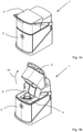
- FIGS 1A and 1B show perspective views of a microwave oven 1 according to the invention.
- the microwave oven 1 comprises a lower part 2 and an upper part 3 which can be pivoted in a direction as indicated by arrow P1 from a closed position as shown in figure 1A to an open position as shown in figure 1B .
- the lower part 2 comprises a holder 4 in which a vessel 5 like a cup can be removable placed in the open position of the microwave oven 1.
- the foodstuff can be a liquid like soup or sauce or a mixture to prepare a scrambled egg comprising egg or only egg white and if desired milk, mushrooms, tomatoes, unions bacon, chicken, banana, cream, yoghurt, salmon, herbs of any kind (pepper, salt, oregano), leek, capers, cheese etc.
- the foodstuff can also be a mixture for a shredded pancake like Kaiserschmarrn, noodles or a muffin.
- FIG 2A is a detailed cross sections of the microwave oven 1 as shown in figure 1A , showing the holder 4 with the vessel 5 located in the cooking cavity 6. In the vessel 5 foodstuff 7 is present.
- the cooking cavity 6 is bounded by an upper wall 8 being provided with a slotted hole like opening 9.
- the upper part 3 of the microwave oven 1 is provided with a displacement device 10 mounted on top of the upper wall 8.
- a stirrer member 11 can be moved through the opening 9 in the upper wall 8 into the vessel 5 and depending on the level of the foodstuff 7 in the vessel 5, also in the foodstuff 7.
- the stirrer member 11 is plate shaped and comprises a first part 12 and a second part 13 extending under an angle with the first part 12.
- the first part 12 is provided at its end with two teeth 14 which will be used to stir the foodstuff 7 during and/or after cooking in the microwave oven 1 as well as eating utensil for a user to eat the prepared foodstuff from the vessel 5, after the vessel 5 has been taken out of the microwave oven 1.
- the second part 13 comprises at its end with a U shaped opening 15 as well as on one side wall 16 abutment portions 17, 18.
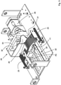
- Figure 3 shows a perspective view of a first embodiment of a displacement device 10 of the microwave oven 1.
- the displacement device 10 comprises a holder 20 for a number of stirring members 11 being stacked upon each other in a stacking direction indicated by arrow P2 whereby plate-shaped surfaces of adjacent stirring members 11 being in abutment with each other.
- the stack 21 of stirring members 11 is located on the holder 20 and is movable by means of a slidable pushing member 22 under spring force of springs 23 in the stacking direction indicated by arrow P2.
- the slidable pushing member 22 forms a transport mechanism.
- On a side remote of the pushing member 22 a separating device 24 is located.
- the separating device 24 comprises a pivoting mechanism 25 being actuated by a stepping motor 26.
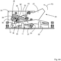
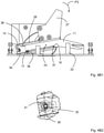
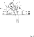
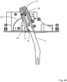
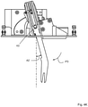
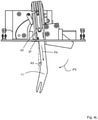
- Figures 4A-4M show detailed side views of the displacement device 10 in several different positions during the insertion of the stirring member 11 into the vessel 5.
- the pivoting mechanism 25 is in its initial position.
- the pivoting mechanism 25 comprises a metal plate 27 being pivotable about a pivot axis 43 in and opposite to a pivot direction indicated by arrow P3.
- the metal plate 27 is connected to a receiving member 28 for receiving a stirrer member 11.
- the receiving member 28 comprises a longitudinal slot 29 wherein a pen 30 is slidable movable.
- the pen 30 is connected to a bearing 31 (see figure 4B2 ) which can roll over a curved path 32 of a frame part 33.
- a spring (not visible) which is connected with an end remote of the pen 30' to pen 34.
- the receiving member 28 also comprises a slot 35 in which a pen 36 can insert and slide.
- a pen 37 is located being movable in a direction parallel to the stacking direction indicated by arrow P2.
- the first stirring member 11 of the stack 21 is being moved under spring force of springs 23 into a stirring member receiving slot 38 of the receiving member 28.
- the pen 30 is located in the U-shaped opening 15, the pen 36 is located opposite the abutment portion 17 and the pen 37 is located opposite the abutment portion 18 of the stirrer member 11.
- the receiving member 28 together with the stirring member 11 are being pivoted in a direction opposite to arrow P3 (see figure 4C ), thereby moving the stirring member 11 through the opening 9 in the upper wall 8 into the cooking cavity 6.
- the bearing 31 with pen 30 rolls over the curved path 32 of the frame part 33 whereby the distance between the bearing 31 and the pen 37 gets smaller.
- the pen 30 will be moved under spring force slightly in the direction indicated by arrow P4 against a wall of the U-shaped opening 15. Due to this movement the abutment portion 17 will become in abutment with pen 36 preventing further movement of the stirrer member 11 in the direction indicated by arrow P4.
- the stirring member 11 is now located in the vessel 5 and if the level of the foodstuff 7 in the vessel 5 is high enough, the stirring member 11 will also be located in the foodstuff 7.
- the microwave oven 1 can be switched on or already be switched on, whereby the foodstuff is exposed to microwave radiation.
- the vessel 5 will be rotated in a manner well known in the art by means of the drive means about a rotating axis 42.
- the receiving member 28 together with the stirring member 11 will be swivelled by swiveling it about pivot axis 43 between an angle A1 ( figure 4J ) of for example 20-30, like 26 degrees and an angle A2 ( figure 4K ) of for example 10-20, like 15 degrees.
- the angle A1, A2 can be amended depending on the desired displacement during swivelling, the size of the vessel 5, the size and shape of the stirring member 11.
- the total length of the stirring member 11 can be between several centimetres up to 20 or 30 centimetres, depending a.o. on the size of the vessel 5.
- the stirring member 11 is being swivelled from at or about a wall of the vessel till near or beyond the centre line of the vessel 5.
- the stirring member 11 extends into the foodstuff, for example just scratching the surface of the foodstuff, a few centimetres like 17-25 millimetres or till just above or to the bottom of the vessel.
- the rotation speed can be in the range of 0,5-100 rpm, preferably 1-60 rpm.
- the swivel speed can be in the range of 2-100, preferably 3-60 swivels per minute.
- the receiving member 28 together with the stirring member 11 are being pivoted further in the direction opposite to arrow P3 to an angle A3 ( figure 4L ) of for example 6 degrees.
- A3 figure 4L
- the pen 37 is being moved in the stacking direction P2, so that the abutment portion 17 is no longer in abutment with the pen 37. This forms a releasing device.
- the stirrer member 11 By opening the microwave oven 1 to the position as shown in figure 1B , the stirrer member 11 will fall out of the receiving member 28 under gravity and/or will stick to the foodstuff 7 and be pulled out of the receiving member 28 by the foodstuff. If not, the user can pull the stirrer member 11 out the receiving member 28 by himself ( figure 4M ).
- FIGs 5 and 6 show perspective views of a second embodiment of a displacement device 110 of the microwave oven 1 as shown in figure 1A and 1B for moving a stirrer member 111 into the cooking cavity.
- the stirrer member 111 comprises a longitudinal strip being curved about an axis extending in the longitudinal direction of the stirrer member 111.
- Such stirrer members 111 can easily be stacked and separated by moving for example the lowest stirrer member 111 in a direction indicated by arrow P11.
- the displacement device 110 comprises a number of rotating rollers 112, 113, 114 through which a separated single stirrer member 111 can be guided in a direction indicated by arrow P12 whereby the curved stirrer member 111 is forced against spring force of the stirrer member 111 to a flat stirrer member 111' in which it is inserted by means of rollers 116 through the opening 9 in the upper wall 8 of the cooking cavity 6.
- the flat stirrer member 111' is no longer located between the rollers 112, 113, 114, it will return under spring force into its curved position.
- the stirrer member 111 will be held at one end near the upper wall 8 and be prevented from moving downwardly. It can be kept still during rotation of the vessel 5, it can be swivelled or it can be rotated as well as being swivelled.
- FIGs 7 and 8 show perspective views of a third embodiment of a displacement device 210 of the microwave oven 1 as shown in figure 1A and 1B for moving stirrer members 211 to the cooking cavity.
- the stirrer member 211 comprises a handle 212 as well as a spoon shaped part 213.
- the stirrer members 211 are stackable whereby main surfaces of the stirrer members 211 are in abutment with each other. After moving one stirrer member 211 away from the stack 214 in a direction P21, the stirrer member 211 is moved by the displacement device 210 in the directions as indicated by arrows P22 and P23 through the opening 9 in the upper wall 8 of the cooking cavity 6 and into the vessel 5.
- the thickened end 215 of the stirrer member 211 can be held in the displacement device 210 during operating the microwave oven 1 and be released after completing the cooking process.
- FIGs 9-12 are perspective views of a fourth embodiment of a displacement device 310 of the microwave oven as shown in figure 1A and 1B for moving stirrer members 311 to the cooking cavity.
- the stirrer member 311 comprises a shaft 312 provided at one end with a ring shaped part 313 and at the other end with a knife shaped part 314.
- the stirrer members 311 can be stacked by mounting the ring shaped parts 313 on a rod 315 of the displacement device 310.
- the rod 315 extends horizontally over a first part 316, whereby the stirrer members 311 are stacked on this horizontally first part 316, comprises a curved part 317 and a second part 318 extending downwardly towards the vessel 5.
- a separated stirrer member 311 is being moved along the first part 316, the curved part 317 and the second part 318, until the ring shaped part 313 of the stirrer member 311 abuts against a thickened end (not visible) of the second part 318. It may also simply rest on a bottom of the vessel 5.
- the ring shaped part 313 comprises a small slot 319, so that the ring shaped part 313 can be opened against spring force to remove the ring shaped part 313 from the second part 318.
- the movement of the stirrer member 11, 111, 211, 311 can also be done when the microwave oven 1 is open, so that by closing the microwave oven 1 the stirrer member 11, 111, 211, 311 is directly inserted into the vessel 5.
- the rotating axis 42 extends preferably vertically but, if desired it can extend under an angle with the vertical.
- FIGS 13-17 show several examples of scrambled egg as prepared by means of the method and microwave oven 1 according to the invention.
- the scrambled eggs have been made from 100 gram Schlemmer Mix of Eipro at a start temperature between 8 and 13 degrees Celsius.
- the cooking time was 60-70 seconds at 1000 Watt.
- stirrer member 11 was positioned over a distance of 17 millimetres in the egg mixture. Since during cooking the egg mixture will rise, the stirrer member 11 will be positioned over a larger distance into the egg mixture. However, the distance to the bottom of the vessel 5 remained the same.
- the rotational speed was in the range of 0,5-100 rpm, preferably 1-60 rpm.
- the swivel speed was in the range of 2-100, preferably 3-60 swivels per minute.
- Figure 13 shows an example with the rotational speed being 5 rpm and the swivel speed being 10 swivels per minute.
- Figure 14 shows an example with the rotational speed being 30 rpm and the swivel speed being 10 swivels per minute.
- Figure 15 shows an example with the rotational speed being 60 rpm and the swivel speed being 10 swivels per minute.
- Figure 16 shows an example whereby during the period that the microwave was switched on, the vessel 5 was rotated but no stirrer member 11 was present.
- the start temperature was 10 degrees Celsius and the end temperature was about 60 degrees Celsius.
- the stirrer member 11 was introduced only after the microwave was switched off. Subsequently, the vessel 5 was rotated at 30 rpm and the stirrer member 11 was swivelled at a swivel speed of 35 swivels per minute.
- Figure 17 shows an example with the rotational speed being 30 rpm and the swivel speed being 35 swivels per minute.
- the start temperature was 9 degrees Celsius and the end temperature was about 60 degrees Celsius. During 10 seconds after the microwave has stopped, so after cooking, the rotation and swivelling continued.
- the microwave oven can have any suitable shape.
- Microwave has the advantage that it does not require any heat up cycle, which is efficient. Steam can be beneficial when higher cooking temperatures are required. Since steam will add moisture to the foodstuff, using steam is advantageous when drying out of food, during heating, becomes critical.
Landscapes
- Engineering & Computer Science (AREA)
- Food Science & Technology (AREA)
- Chemical & Material Sciences (AREA)
- Polymers & Plastics (AREA)
- Health & Medical Sciences (AREA)
- Nutrition Science (AREA)
- Life Sciences & Earth Sciences (AREA)
- Mechanical Engineering (AREA)
- Chemical Kinetics & Catalysis (AREA)
- Electromagnetism (AREA)
- Physics & Mathematics (AREA)
- General Engineering & Computer Science (AREA)
- Combustion & Propulsion (AREA)
- Food-Manufacturing Devices (AREA)
- Electric Ovens (AREA)
- Constitution Of High-Frequency Heating (AREA)
- Electric Stoves And Ranges (AREA)
- Cookers (AREA)
Description
- The invention relates to an oven comprising a cooking cavity, a stirring member extending, in use, into foodstuff contained in a vessel disposed in the cooking cavity as well as drive means to provide, in use, relative movement between the stirring member and the vessel.
- The invention also relates to a method for stirring foodstuff contained in a vessel disposed in a cooking cavity of an oven by means of a stirring member, whereby the vessel is being relatively moved with respect to the stirring member.
- By a microwave oven and method as known from
GB2159027 - By this microwave oven a lid is needed to support the stirring paddle and this lid must be placed on top of the bowl before the bowl can be placed in the microwave oven cavity. After preparing the foodstuff, the lid and the stirring paddle needs to be cleaned before it can be used again. Furthermore, rotation of the paddle depends on the rotation of the bowl.
- For several kinds of foodstuff relative rotational movement between the bowl and paddle will not provide sufficient agitation of the foodstuff to ensure a proper cooking result.
- Another microwave oven of the prior art is disclosed in
US2004/251250 . - At least one of the objects of the invention is to provide an oven whereby agitation of the foodstuff is being improved.
- This object is accomplished with the oven according to the invention in that the drive means comprises means to rotate, in use, the vessel with respect to the stirring member about a rotating axis, whilst the oven comprises a swivel means comprising a motor to swivel, in use, the stirring member by means of the motor about a swivel axis extending at an angle of between 60-120 degrees, preferably substantially perpendicular to the rotating axis.
- An oven according to this patent application is every device by means of which the foodstuff can be heated. The vessel can be located inside the cooking cavity of the oven.
- Rotating of the vessel ensures that a more uniform heating of the foodstuff in the vessel occurs by preventing the formation of hotspots. The foodstuff is mixed inside the vessel by means of the stirrer member, which further prevents the formation of hotspots. In case that the foodstuff for example changes from liquid to a more solid state like by scrambled eggs, the stirrer also causes a mixing of the more liquid foodstuff and more solidified foodstuff.
- By also swivelling the stirrer member with respect to the vessel and the foodstuff located therein, the foodstuff is being further mixed. By moving the stirrer member with respect to the foodstuff, it is also prevented that the foodstuff will get attached to the stirrer member and will be moved together with the stirrer mechanism with respect to the vessel. Due to the swivelling movement, the foodstuff is being cut. This is especially interesting by preparing scrambled eggs. Sticking of the foodstuff to the stirrer member depends amongst others on the kind of foodstuff, the material and smoothness of the stirrer member, the rotational speed of the vessel, the swivelling speed of the stirrer member, the shape of the stirrer member and the displacement of the stirrer member.
- Although it is preferred that the swivel axis extends perpendicular to the rotating axis in view of the simplicity of the design, an angle between 60-120 degrees is also possible to still have a swivelling movement in addition to a rotational movement.
- Due to the swivelling motion a better agitation of the foodstuff is obtained.
- In case of trying to cook scrambled eggs without swivelling the stirrer member an egg soufflé would be obtained. Due to the swivelling motion, soft separated pieces of egg will be obtained. The pieces might or might not stick slightly to each other but provide the typical appearance of scrambled eggs.
- During or after cooking, the stirrer can be used as cutlery. Depending on the shape of the stirring member, the stirring member can be used as an eating utensil, like a fork, spoon, spork, skewer. The stirring member can be disposable or reusable.
- The vessel can be any kind of holder, bag, cup, bag etc. suitable to contain the foodstuff.
- It has to be noted that
US20040251250A1 discloses a microwave oven mixing device including a mounting bracket structured for securement to an interior surface of a cooking compartment of a microwave oven, a horizontal beam pivotally mounted to the mounting bracket and structured for pivotal movement on the mounting bracket during operation of the microwave oven, and a mixing blade operatively connected to the horizontal beam and structured for placement within a food container during operation of the microwave oven. The mixing blade is connected via a vertical arm to the horizontal beam. Rotation of vertical arm about a horizontal axis allows the mixing blade secured to the vertical arm to be moved upwardly and out of the way of a food container when the container is placed in or removed from a microwave oven.US20040251250A1 does not disclose to swivel in use of the oven the mixing blade through the food in the food container. It does also not disclose that the mixing blade is being swivelled by means and under control of a motor and that it is swivelled over a predetermined angle. - It has to be noted that
WO9310648A1 DE3930337A1 also disclose microwave oven mixing devices. Also by these known devices the mixing blade is not actively swivelled in use under control of a motor over a predetermined angle. - An embodiment of the oven according to the invention is characterized in that the swivel speed to swivel the stirring member back and forth about the swivel axis is in the range of 2-100, preferably 3-60 swivels per minute.
- Experiments have shown that at such swivel speed a good agitation of the foodstuff is obtained.
- Another embodiment of the oven according to the invention is characterized in that the rotational speed to rotate, in use, the vessel with respect to the stirring about the rotating axis is in the range of 0,5-100 rpm, preferably 1-60 rpm.
- Experiments have shown that at such rotational speed a good agitation of the foodstuff is obtained.
- Another embodiment of the oven according to the invention is characterized in that the swivel speed and the rotational speed have a ratio in the range of 1:2.
- With such ratio sufficient rotation and swivelling of the foodstuff will take place.
- Another embodiment of the oven according to the invention is characterized in that the stirring member is swivelable about the swivel axis over an angle between 5 and 60 degrees to the vertical.
- The stirrer member can be swivelled from one wall of the vessel to an opposite wall of vessel. However, since the vessel is also being rotated it will be normally sufficient to swivel the stirrer member from at or about a wall of the vessel till near or beyond the centre line of the vessel.
- Another embodiment of the oven according to the invention is characterized in that the oven is a microwave oven, a steam oven or another kind of oven.
- By means of microwaves or steam foodstuff can easily be heated at a desired speed to a desired temperature.
- The invention also relates to a method for stirring foodstuff contained in a vessel disposed in the cooking cavity of an oven by means of a stirring member, whereby the vessel is being rotated with respect to the stirring member about a rotating axis, whilst the stirring member is being swivelled by means of a motor about a swivel axis extending at an angle of between 60-120 degrees, preferably substantially perpendicular to the rotating axis.
- Due to the swivelling motion a better agitation of the foodstuff is obtained
- An embodiment of the method according to the invention is characterized in that the stirring member is swivelled through the foodstuff during and/or after cooking the foodstuff.
- Depending on the kind of foodstuff and the required cooking result, it is possible to swivel the stirring member through the foodstuff during cooking the foodstuff and/or after cooking the foodstuff.
- Swivelling only after cooking will lead to a kind of cutting of the prepared foodstuff.
- Another embodiment of the method according to the invention is characterized in that the foodstuff comprises at least liquid egg, which is being cooked by microwaves, steaming or other means in the oven being respectively a microwave oven, a steam oven or other kind of oven, whereby the egg is being solidified, whilst during and/or after solidification the stirring is swivelled through the egg to obtain a scrambled egg.
- So far it was not possible to prepare scrambled eggs in a microwave oven since by no prior art microwave oven a stirrer member can be rotated as well as stirred with respect to the vessel, which kind of motion provides the cooked egg with scrambled egg appearance with pieces of cooked egg. The same holds true for a steam oven. The foodstuff may also comprise an egg mixture, which foodstuff after cooking has a scrambled egg appearance with pieces of cooked egg mixture.
- The oven and method according to the invention will further be explained with reference to the drawings, wherein,
-
figure 1A and 1B are perspective views of a microwave oven according to the invention, whereby infigure 1A the microwave oven is being closed and infigure 1B the microwave oven is being opened, -
figure 2A-2C are detailed cross sections of the microwave oven as shown infigure 1A , in respectively a position wherein the stirring member is located outside the cooking cavity, is located inside the vessel in a first position and is located inside the vessel in a second position, -
figure 3 is a perspective view of a first embodiment of a displacement device of the microwave oven as shown infigure 1A and 1B , -
figures 4A-4M are detailed side views of the displacement device as shown infigure 3 in several different positions during the insertion of the stirring member into the vessel, -
figures 5 and6 are perspective views of a second embodiment of a displacement device of the microwave oven as shown infigure 1A and 1B , -
figures 7 and8 are perspective views of a third embodiment of a displacement device of the microwave oven as shown infigure 1A and 1B , -
figures 9-12 are perspective views of a fourth embodiment of a displacement device of the microwave oven as shown infigure 1A and 1B , -
figures 13- 17 are top views of a vessel comprising scrambled eggs as prepared with the microwave oven according to the invention. - In the drawings, like reference numerals refer to like elements.
-
Figures 1A and 1B show perspective views of amicrowave oven 1 according to the invention. Themicrowave oven 1 comprises alower part 2 and anupper part 3 which can be pivoted in a direction as indicated by arrow P1 from a closed position as shown infigure 1A to an open position as shown infigure 1B . - The
lower part 2 comprises aholder 4 in which avessel 5 like a cup can be removable placed in the open position of themicrowave oven 1. - In the
vessel 5 foodstuff to be prepared in themicrowave oven 1 can be inserted. The foodstuff can be a liquid like soup or sauce or a mixture to prepare a scrambled egg comprising egg or only egg white and if desired milk, mushrooms, tomatoes, unions bacon, chicken, banana, cream, yoghurt, salmon, herbs of any kind (pepper, salt, oregano), leek, capers, cheese etc. The foodstuff can also be a mixture for a shredded pancake like Kaiserschmarrn, noodles or a muffin. -
Figure 2A is a detailed cross sections of themicrowave oven 1 as shown infigure 1A , showing theholder 4 with thevessel 5 located in thecooking cavity 6. In thevessel 5foodstuff 7 is present. Thecooking cavity 6 is bounded by anupper wall 8 being provided with a slotted hole likeopening 9. - The
upper part 3 of themicrowave oven 1 is provided with adisplacement device 10 mounted on top of theupper wall 8. As will be explained here below, by means of the displacement device 10 astirrer member 11 can be moved through theopening 9 in theupper wall 8 into thevessel 5 and depending on the level of thefoodstuff 7 in thevessel 5, also in thefoodstuff 7. - The
stirrer member 11 is plate shaped and comprises afirst part 12 and asecond part 13 extending under an angle with thefirst part 12. Thefirst part 12 is provided at its end with twoteeth 14 which will be used to stir thefoodstuff 7 during and/or after cooking in themicrowave oven 1 as well as eating utensil for a user to eat the prepared foodstuff from thevessel 5, after thevessel 5 has been taken out of themicrowave oven 1. - The
second part 13 comprises at its end with a U shaped opening 15 as well as on oneside wall 16abutment portions -
Figure 3 shows a perspective view of a first embodiment of adisplacement device 10 of themicrowave oven 1. - The
displacement device 10 comprises aholder 20 for a number of stirringmembers 11 being stacked upon each other in a stacking direction indicated by arrow P2 whereby plate-shaped surfaces of adjacent stirringmembers 11 being in abutment with each other. Thestack 21 of stirringmembers 11 is located on theholder 20 and is movable by means of aslidable pushing member 22 under spring force ofsprings 23 in the stacking direction indicated by arrow P2. Theslidable pushing member 22 forms a transport mechanism. On a side remote of the pushing member 22 aseparating device 24 is located. The separatingdevice 24 comprises apivoting mechanism 25 being actuated by a steppingmotor 26. -
Figures 4A-4M show detailed side views of thedisplacement device 10 in several different positions during the insertion of the stirringmember 11 into thevessel 5. - In
figure 4A thepivoting mechanism 25 is in its initial position. Thepivoting mechanism 25 comprises ametal plate 27 being pivotable about apivot axis 43 in and opposite to a pivot direction indicated by arrow P3. Themetal plate 27 is connected to a receivingmember 28 for receiving astirrer member 11. The receivingmember 28 comprises alongitudinal slot 29 wherein apen 30 is slidable movable. Thepen 30 is connected to a bearing 31 (seefigure 4B2 ) which can roll over acurved path 32 of aframe part 33. Connected to the pen 30' is a spring (not visible) which is connected with an end remote of the pen 30' to pen 34. - The receiving
member 28 also comprises aslot 35 in which apen 36 can insert and slide. - At a distance from the pen 36 a
pen 37 is located being movable in a direction parallel to the stacking direction indicated by arrow P2. - To insert a stirring
member 11 into the receivingmember 28 thepivoting mechanism 25 is being pivoted in the direction as indicated by arrow P3 to the position as shown infigure 4B1 . - In said position, the first stirring
member 11 of thestack 21 is being moved under spring force ofsprings 23 into a stirringmember receiving slot 38 of the receivingmember 28. In this position thepen 30 is located in theU-shaped opening 15, thepen 36 is located opposite theabutment portion 17 and thepen 37 is located opposite theabutment portion 18 of thestirrer member 11. - When moving the receiving
member 28 to the position as shown infigure 4B1 and an enlarged part thereof as shown infigure 4B2 , the bearing 31 rolls over thecurved path 32 of theframe part 33, thereby tensioning the spring connected to the pen 30'. In this position thebearing 31 and thepen 30 are located the furthest away from thepen 34. - After the stirring
member 11 is being inserted into the receivingmember 28, the receivingmember 28 together with the stirringmember 11 are being pivoted in a direction opposite to arrow P3 (seefigure 4C ), thereby moving the stirringmember 11 through theopening 9 in theupper wall 8 into thecooking cavity 6. The bearing 31 withpen 30 rolls over thecurved path 32 of theframe part 33 whereby the distance between the bearing 31 and thepen 37 gets smaller. Thepen 30 will be moved under spring force slightly in the direction indicated by arrow P4 against a wall of theU-shaped opening 15. Due to this movement theabutment portion 17 will become in abutment withpen 36 preventing further movement of thestirrer member 11 in the direction indicated by arrow P4. - In the steps as shown in
figures 4D and4E the receivingmember 28 together with the stirringmember 11 are being pivoted further in the direction opposite to arrow P3 until a stoppingmember 39 connected to pen 36 viaelement 40 abuts against astop 41 offrame part 33. - By further pivoting the receiving
member 28 together with the stirringmember 11 in the direction opposite to arrow P3, theslot 35 and theabutment portion 17 moves away from thepen 36, so that the movement of the stirringmember 11 in the direction as indicated by arrow P4 is no longer prevented (seefigure 4F ) due to which the stirringmember 11 will be moved under spring force on pen 30' in the direction as indicated by arrow P4 (seefigures 4F ,4G ) until theabutment portion 17 rests against the pen 37 (seefigure 4H ). Infigure 4H it can be seen that the bearing 31 withpen 30 now rests again on thecurved path 32. - The stirring
member 11 is now located in thevessel 5 and if the level of thefoodstuff 7 in thevessel 5 is high enough, the stirringmember 11 will also be located in thefoodstuff 7. - The
microwave oven 1 can be switched on or already be switched on, whereby the foodstuff is exposed to microwave radiation. During this process, thevessel 5 will be rotated in a manner well known in the art by means of the drive means about a rotatingaxis 42. The receivingmember 28 together with the stirringmember 11 will be swivelled by swiveling it aboutpivot axis 43 between an angle A1 (figure 4J ) of for example 20-30, like 26 degrees and an angle A2 (figure 4K ) of for example 10-20, like 15 degrees. The angle A1, A2 can be amended depending on the desired displacement during swivelling, the size of thevessel 5, the size and shape of the stirringmember 11. The total length of the stirringmember 11 can be between several centimetres up to 20 or 30 centimetres, depending a.o. on the size of thevessel 5. Preferably the stirringmember 11 is being swivelled from at or about a wall of the vessel till near or beyond the centre line of thevessel 5. During rotation and swivelling the stirringmember 11 extends into the foodstuff, for example just scratching the surface of the foodstuff, a few centimetres like 17-25 millimetres or till just above or to the bottom of the vessel. - By the combined simultaneously motion of rotating the
vessel 5 about rotatingaxis 42 and swivelling thestirrer member 11 aboutpivot axis 43 extending perpendicular to the rotating axis 42 a good stirring of the foodstuff occurs, thereby preventing hotspots, as well as mixing and cutting the foodstuff. The rotation speed can be in the range of 0,5-100 rpm, preferably 1-60 rpm. The swivel speed can be in the range of 2-100, preferably 3-60 swivels per minute. - As soon as the foodstuff is ready, the receiving
member 28 together with the stirringmember 11 are being pivoted further in the direction opposite to arrow P3 to an angle A3 (figure 4L ) of for example 6 degrees. When moving to this angle A3, thepen 37 is being moved in the stacking direction P2, so that theabutment portion 17 is no longer in abutment with thepen 37. This forms a releasing device. - By opening the
microwave oven 1 to the position as shown infigure 1B , thestirrer member 11 will fall out of the receivingmember 28 under gravity and/or will stick to thefoodstuff 7 and be pulled out of the receivingmember 28 by the foodstuff. If not, the user can pull thestirrer member 11 out the receivingmember 28 by himself (figure 4M ). -
Figures 5 and6 show perspective views of a second embodiment of adisplacement device 110 of themicrowave oven 1 as shown infigure 1A and 1B for moving astirrer member 111 into the cooking cavity. Thestirrer member 111 comprises a longitudinal strip being curved about an axis extending in the longitudinal direction of thestirrer member 111.Such stirrer members 111 can easily be stacked and separated by moving for example thelowest stirrer member 111 in a direction indicated by arrow P11. Thedisplacement device 110 comprises a number ofrotating rollers single stirrer member 111 can be guided in a direction indicated by arrow P12 whereby thecurved stirrer member 111 is forced against spring force of thestirrer member 111 to a flat stirrer member 111' in which it is inserted by means ofrollers 116 through theopening 9 in theupper wall 8 of thecooking cavity 6. As soon as the flat stirrer member 111' is no longer located between therollers microwave oven 1 thestirrer member 111 will be held at one end near theupper wall 8 and be prevented from moving downwardly. It can be kept still during rotation of thevessel 5, it can be swivelled or it can be rotated as well as being swivelled. -
Figures 7 and8 show perspective views of a third embodiment of adisplacement device 210 of themicrowave oven 1 as shown infigure 1A and 1B for movingstirrer members 211 to the cooking cavity. Thestirrer member 211 comprises ahandle 212 as well as a spoon shapedpart 213. Thestirrer members 211 are stackable whereby main surfaces of thestirrer members 211 are in abutment with each other. After moving onestirrer member 211 away from thestack 214 in a direction P21, thestirrer member 211 is moved by thedisplacement device 210 in the directions as indicated by arrows P22 and P23 through theopening 9 in theupper wall 8 of thecooking cavity 6 and into thevessel 5. Thethickened end 215 of thestirrer member 211 can be held in thedisplacement device 210 during operating themicrowave oven 1 and be released after completing the cooking process. -
Figures 9-12 are perspective views of a fourth embodiment of adisplacement device 310 of the microwave oven as shown infigure 1A and 1B for movingstirrer members 311 to the cooking cavity. Thestirrer member 311 comprises ashaft 312 provided at one end with a ring shapedpart 313 and at the other end with a knife shapedpart 314. Thestirrer members 311 can be stacked by mounting the ring shapedparts 313 on arod 315 of thedisplacement device 310. Therod 315 extends horizontally over afirst part 316, whereby thestirrer members 311 are stacked on this horizontallyfirst part 316, comprises acurved part 317 and asecond part 318 extending downwardly towards thevessel 5. A separatedstirrer member 311 is being moved along thefirst part 316, thecurved part 317 and thesecond part 318, until the ring shapedpart 313 of thestirrer member 311 abuts against a thickened end (not visible) of thesecond part 318. It may also simply rest on a bottom of thevessel 5. Preferably the ring shapedpart 313 comprises a small slot 319, so that the ring shapedpart 313 can be opened against spring force to remove the ring shapedpart 313 from thesecond part 318. - The movement of the
stirrer member microwave oven 1 is open, so that by closing themicrowave oven 1 thestirrer member vessel 5. - It is also possible to only rotate the
vessel 5 with respect to thestirrer member vessel 5 or thestirrer member vessel 5 and thestirrer member stirrer member - The rotating
axis 42 extends preferably vertically but, if desired it can extend under an angle with the vertical. - It is also possible to swivel the stirring
member 11 between opposite walls of thevessel 5. -
Figures 13-17 show several examples of scrambled egg as prepared by means of the method andmicrowave oven 1 according to the invention. - The scrambled eggs have been made from 100 gram Schlemmer Mix of Eipro at a start temperature between 8 and 13 degrees Celsius. The cooking time was 60-70 seconds at 1000 Watt.
- Initially the
stirrer member 11 was positioned over a distance of 17 millimetres in the egg mixture. Since during cooking the egg mixture will rise, thestirrer member 11 will be positioned over a larger distance into the egg mixture. However, the distance to the bottom of thevessel 5 remained the same. - The rotational speed was in the range of 0,5-100 rpm, preferably 1-60 rpm.
- The swivel speed was in the range of 2-100, preferably 3-60 swivels per minute.
-
Figure 13 shows an example with the rotational speed being 5 rpm and the swivel speed being 10 swivels per minute. -
Figure 14 shows an example with the rotational speed being 30 rpm and the swivel speed being 10 swivels per minute. -
Figure 15 shows an example with the rotational speed being 60 rpm and the swivel speed being 10 swivels per minute. - In all three examples scrambled
egg 50 was obtained. Similar results were obtained by higher swivel speeds. -
Figure 16 shows an example whereby during the period that the microwave was switched on, thevessel 5 was rotated but nostirrer member 11 was present. The start temperature was 10 degrees Celsius and the end temperature was about 60 degrees Celsius. Thestirrer member 11 was introduced only after the microwave was switched off. Subsequently, thevessel 5 was rotated at 30 rpm and thestirrer member 11 was swivelled at a swivel speed of 35 swivels per minute. -
Figure 17 shows an example with the rotational speed being 30 rpm and the swivel speed being 35 swivels per minute. The start temperature was 9 degrees Celsius and the end temperature was about 60 degrees Celsius. During 10 seconds after the microwave has stopped, so after cooking, the rotation and swivelling continued. - In both examples as shown in
figures 16 and 17 individual pieces of scrambledeggs 50 are clearly visible. - It has to be noted that without stirring a soufflé would be obtained in the
vessel 5 with a homogenous, almost flat top surface. - The microwave oven can have any suitable shape.
- For different foodstuffs the time, temperatures, swivel speeds and rotational speeds etc. can easily experimentally be determined.
- It is possible let the stirrer member drop into the foodstuff during or just after cooking or just before bringing the
microwave oven 1 to the open position as shown infigure 1B . - The embodiments as shown above have been described regarding a microwave oven. The same results can be obtained by using a steam oven instead of a microwave oven or by using another kind of oven suitable for heating the foodstuff.
- Microwave has the advantage that it does not require any heat up cycle, which is efficient. Steam can be beneficial when higher cooking temperatures are required. Since steam will add moisture to the foodstuff, using steam is advantageous when drying out of food, during heating, becomes critical.
-
- 1
- microwave oven
- 2
- lower part
- 3
- upper part
- 4
- holder
- 5
- vessel
- 6
- cooking cavity
- 7
- foodstuff
- 8
- upper wall
- 9
- opening
- 10
- displacement device
- 11
- stirrer member
- 12
- first part
- 13
- second part
- 14
- teeth
- 15
- U shaped opening
- 16
- wall
- 17
- abutment portion
- 18
- abutment portion
- 20
- holder
- 21
- stack
- 22
- pushing member
- 23
- spring
- 24
- separating device
- 25
- pivoting device
- 26
- stepping motor
- 27
- metal plate
- 28
- receiving member
- 29
- longitudinal slot
- 30
- pen
- 30'
- pen
- 31
- bearing
- 32
- curved path
- 33
- frame part
- 34
- pen
- 35
- slot
- 36
- pen
- 37
- pen
- 38
- receiving slot
- 39
- stopping member
- 40
- element
- 41
- stop
- 42
- rotating axis
- 43
- pivot axis
- 110
- displacement device
- 111
- curved stirrer member
- 111'
- flat stirrer member
- 112
- roller
- 113
- roller
- 114
- roller
- 116
- roller
- 210
- displacement device
- 211
- stirrer member
- 212
- handle
- 213
- spoon shaped part
- 214
- stack
- 215
- thickened end
- 310
- displacement device
- 311
- stirrer member
- 312
- shaft
- 313
- ring shaped part
- 314
- knife shaped part
- 315
- rod
- 316
- first part
- 317
- curved part
- 318
- second part
- 319
- slot
- A1
- angle
- A2
- angle
- A3
- angle
- P1
- arrow
- P2
- arrow
- P3
- arrow
- P4
- arrow
- P21
- arrow
- P22
- arrow
Claims (14)
- An oven (1) comprising a cooking cavity (6), a stirring member (11, 111, 211, 311) extending, in use, into foodstuff (7) contained in a vessel (5) disposed in the cooking cavity (6) as well as drive means to provide, in use, relative movement between the stirring member (11, 111, 211, 311) and the vessel (5), characterized in that the drive means comprises means to rotate, in use, the vessel (5) with respect to the stirring member (11, 111, 211, 311) about a rotating axis (42), whilst the oven (1) comprises a swivel means comprising a motor (26) to swivel, in use, the stirring member (11, 111, 211, 311) by means of the motor (26) about a swivel axis (43) extending at an angle of between 60-120 degrees, preferably substantially perpendicular to the rotating axis (42).
- An oven (1) according to claim 1, characterized in that the swivel speed to swivel the stirring member (11, 111, 211, 311) back and forth about the swivel axis (43) is in the range of 2-100, preferably 3-60 swivels per minute.
- An oven (1) according to claim 1 or 2, characterized in that the rotational speed to rotate, in use, the vessel (5) with respect to the stirring member (11, 111, 211, 311) about the rotating axis (42) is in the range of 0,5-100 rpm, preferably 1-60 rpm.
- An oven (1) according to claim 1, 2 or 3, characterized in that the swivel speed and the rotational speed have a ratio in the range of 1:2.
- An oven (1) according to one of the preceding claims, characterized in that the stirring member (11, 111, 211, 311) is swivelable about the swivel axis (43) over an angle between 5 and 60 degrees to the vertical.
- An oven according to one of the preceding claims, characterized in that the oven is a microwave oven, steam oven or another kind of oven.
- A method for stirring foodstuff contained in a vessel disposed in a cooking cavity of an oven (1) by means of a stirring member (11, 111, 211, 311), whereby the vessel (5) is being relatively moved with respect to the stirring member (11, 111, 211, 311), characterized in that that the vessel (5) is being rotated with respect to the stirring member (11, 111, 211, 311) about a rotating axis (42), whilst the stirring member (11, 111, 211, 311) is being swivelled by means of a motor about a swivel axis (43) extending at an angle of between 60-120 degrees, preferably substantially perpendicular to the rotating axis (42).
- A method according to claim 7 characterized in that the swivel speed to
swivel the stirring member (11, 111, 211, 311) back and forth about the swivel axis (43) is in the range of 2-100, preferably 3-60 swivels per minute. - A method according to claim 7 or 8, characterized in that the rotational
speed to rotate, in use, the vessel (5) with respect to the stirring member (11, 111, 211, 311) about the rotating axis (42) is in the range of 0,5-100 rpm, preferably 1-60 rpm. - A method according to claim 7, 8 or 9, characterized in that the swivel speed
and the rotational speed have a ratio in the range of 1:2. - A method according to one of the preceding claims 7-10 , characterized in that
the stirring member (11, 111, 211, 311) is swivelable about the swivel axis (43) over an angle between 1 and 60 degrees. - A method according to one of the preceding claims, characterized in that the foodstuff is being heated in the oven by means of microwaves, steam or other means.
- A method according to one of the preceding claims 7-11, characterized in
that the stirring member (11, 111, 211, 311) is swivelled through the foodstuff during and/or after cooking the foodstuff. - A method according to one of the preceding claims 7-12, characterized in
that the foodstuff comprises at least liquid egg, which is being cooked by microwaves, steam or other means in the oven (1), being respectively a microwave oven, a steam oven or other kind of oven whereby the egg is being solidified, whilst during and/or after solidification the stirring member (11, 111, 211, 311) is swivelled through the egg to obtain a scrambled egg.
Applications Claiming Priority (2)
| Application Number | Priority Date | Filing Date | Title |
|---|---|---|---|
| NL2021240A NL2021240B1 (en) | 2018-07-04 | 2018-07-04 | Microwave oven, as well as a method for stirring foodstuff contained in a vessel disposed in the cooking cavity of such a microwave oven |
| PCT/EP2019/067737 WO2020007861A1 (en) | 2018-07-04 | 2019-07-02 | An oven, as well as a method for stirring foodstuff contained in a vessel disposed in the cooking cavity of such an oven |
Publications (2)
| Publication Number | Publication Date |
|---|---|
| EP3818782A1 EP3818782A1 (en) | 2021-05-12 |
| EP3818782B1 true EP3818782B1 (en) | 2022-02-23 |
Family
ID=63722728
Family Applications (1)
| Application Number | Title | Priority Date | Filing Date |
|---|---|---|---|
| EP19733824.7A Active EP3818782B1 (en) | 2018-07-04 | 2019-07-02 | An oven, as well as a method for stirring foodstuff contained in a vessel disposed in the cooking cavity of such an oven |
Country Status (13)
| Country | Link |
|---|---|
| US (1) | US12318034B2 (en) |
| EP (1) | EP3818782B1 (en) |
| JP (1) | JP7369186B2 (en) |
| CN (1) | CN112335337B (en) |
| AU (1) | AU2019298581B2 (en) |
| CA (1) | CA3103885A1 (en) |
| ES (1) | ES2910267T3 (en) |
| HU (1) | HUE058358T2 (en) |
| IL (1) | IL279701B2 (en) |
| MX (1) | MX2020014285A (en) |
| NL (1) | NL2021240B1 (en) |
| PL (1) | PL3818782T3 (en) |
| WO (1) | WO2020007861A1 (en) |
Families Citing this family (2)
| Publication number | Priority date | Publication date | Assignee | Title |
|---|---|---|---|---|
| CN114158675B (en) * | 2021-11-17 | 2024-01-05 | 米旗食品股份有限公司 | Steaming machine for processing sweet potatoes |
| US11805881B1 (en) * | 2022-11-09 | 2023-11-07 | Enso Wax Llc | Wax warmer with automated stirring |
Family Cites Families (14)
| Publication number | Priority date | Publication date | Assignee | Title |
|---|---|---|---|---|
| GB2159027B (en) | 1984-05-15 | 1987-09-09 | Thorn Emi Domestic Applicances | Improvements in or relating to microwave ovens |
| FR2588063B1 (en) * | 1985-10-01 | 1987-12-18 | Boulard Michel | MICROWAVE OVEN WITH MOBILE EQUIPMENT AND ACCESSORY FOR THIS OVEN |
| US4904834A (en) * | 1987-10-16 | 1990-02-27 | Raytheon Company | Mixing attachment for microwave oven turntables |
| FR2632175B1 (en) * | 1988-06-07 | 1991-10-31 | Boulard Michel | AGITATOR, ESPECIALLY FOR MICROWAVE OVENS |
| DE3930337A1 (en) * | 1989-09-12 | 1991-03-14 | Reinhard Schulze | Boosting microwave effects on flowing material - by internal displacement with mechanical stirrer or bellow |
| US5021621A (en) * | 1990-04-17 | 1991-06-04 | Martha Demmer | Microwave oven having integral mixing assembly |
| GB9124283D0 (en) * | 1991-11-15 | 1992-01-08 | Woodman David G | Stirring in microwave ovens improvements |
| US5899565A (en) * | 1998-03-24 | 1999-05-04 | Camezon; Raymond E. | Microwave resistant mixing device |
| US6933484B2 (en) * | 2003-03-05 | 2005-08-23 | Jeffrey A. Lindley | Microwave oven with food stirring device |
| US20040251250A1 (en) * | 2003-06-10 | 2004-12-16 | Haedrich Michael Steven | Microwave oven mixing device and method of using the same |
| GB2434328A (en) * | 2006-01-24 | 2007-07-25 | Matthew Harry Thompson | Microwave stirrer |
| JP5856774B2 (en) * | 2011-07-29 | 2016-02-10 | 株式会社フジイ機械製作所 | Vertical stirring device |
| US9173516B1 (en) * | 2012-05-11 | 2015-11-03 | Michael G Messer | Microwave oven mixing device |
| CN103750755A (en) * | 2014-02-14 | 2014-04-30 | 周林斌 | Oven with detachable upper cover and use method thereof |
-
2018
- 2018-07-04 NL NL2021240A patent/NL2021240B1/en not_active IP Right Cessation
-
2019
- 2019-07-02 CN CN201980043406.9A patent/CN112335337B/en active Active
- 2019-07-02 IL IL279701A patent/IL279701B2/en unknown
- 2019-07-02 AU AU2019298581A patent/AU2019298581B2/en active Active
- 2019-07-02 EP EP19733824.7A patent/EP3818782B1/en active Active
- 2019-07-02 HU HUE19733824A patent/HUE058358T2/en unknown
- 2019-07-02 CA CA3103885A patent/CA3103885A1/en active Pending
- 2019-07-02 WO PCT/EP2019/067737 patent/WO2020007861A1/en not_active Ceased
- 2019-07-02 MX MX2020014285A patent/MX2020014285A/en unknown
- 2019-07-02 ES ES19733824T patent/ES2910267T3/en active Active
- 2019-07-02 US US17/257,562 patent/US12318034B2/en active Active
- 2019-07-02 JP JP2021522131A patent/JP7369186B2/en active Active
- 2019-07-02 PL PL19733824.7T patent/PL3818782T3/en unknown
Also Published As
| Publication number | Publication date |
|---|---|
| JP2021530667A (en) | 2021-11-11 |
| IL279701A (en) | 2021-03-01 |
| CA3103885A1 (en) | 2020-01-09 |
| CN112335337B (en) | 2023-09-29 |
| ES2910267T3 (en) | 2022-05-12 |
| IL279701B1 (en) | 2024-09-01 |
| IL279701B2 (en) | 2025-01-01 |
| US12318034B2 (en) | 2025-06-03 |
| EP3818782A1 (en) | 2021-05-12 |
| AU2019298581A1 (en) | 2021-01-14 |
| HUE058358T2 (en) | 2022-07-28 |
| MX2020014285A (en) | 2021-06-08 |
| WO2020007861A1 (en) | 2020-01-09 |
| CN112335337A (en) | 2021-02-05 |
| NL2021240B1 (en) | 2020-01-15 |
| AU2019298581B2 (en) | 2024-06-27 |
| PL3818782T3 (en) | 2022-08-08 |
| JP7369186B2 (en) | 2023-10-25 |
| US20210298518A1 (en) | 2021-09-30 |
Similar Documents
| Publication | Publication Date | Title |
|---|---|---|
| JP7519662B2 (en) | AUTOMATED FOOD PREPARATION METHOD AND APPARATUS - Patent application | |
| US20210100396A1 (en) | Methods and Apparatus for Automated Food Preparation | |
| RU2759254C2 (en) | Magnetic transmission with high torque index for churning nozzle | |
| AU2019298581B2 (en) | An oven, as well as a method for stirring foodstuff contained in a vessel disposed in the cooking cavity of such an oven | |
| CN112739241A (en) | System for preparing and presenting food products | |
| BE1004702A6 (en) | Heating unit for edibles. | |
| EP3818781B1 (en) | An oven, as well as a method for stirring foodstuff contained in a vessel disposed in the cooking cavity of such an oven | |
| CN1295445A (en) | Process and corresponding machine for preparation of ready-cooked and semi-cooked dishes | |
| HK40043230B (en) | An oven, a method for stirring foodstuff in such an oven and a stirrer member for such an oven | |
| CN1173117A (en) | Roasting apparatus for bakeable food | |
| HK40043231B (en) | An oven, as well as a method for stirring foodstuff contained in a vessel disposed in the cooking cavity of such an oven | |
| HK40043231A (en) | An oven, as well as a method for stirring foodstuff contained in a vessel disposed in the cooking cavity of such an oven | |
| HK40043230A (en) | An oven, a method for stirring foodstuff in such an oven and a stirrer member for such an oven |
Legal Events
| Date | Code | Title | Description |
|---|---|---|---|
| STAA | Information on the status of an ep patent application or granted ep patent |
Free format text: STATUS: UNKNOWN |
|
| STAA | Information on the status of an ep patent application or granted ep patent |
Free format text: STATUS: THE INTERNATIONAL PUBLICATION HAS BEEN MADE |
|
| PUAI | Public reference made under article 153(3) epc to a published international application that has entered the european phase |
Free format text: ORIGINAL CODE: 0009012 |
|
| STAA | Information on the status of an ep patent application or granted ep patent |
Free format text: STATUS: REQUEST FOR EXAMINATION WAS MADE |
|
| 17P | Request for examination filed |
Effective date: 20201215 |
|
| AK | Designated contracting states |
Kind code of ref document: A1 Designated state(s): AL AT BE BG CH CY CZ DE DK EE ES FI FR GB GR HR HU IE IS IT LI LT LU LV MC MK MT NL NO PL PT RO RS SE SI SK SM TR |
|
| DAV | Request for validation of the european patent (deleted) | ||
| DAX | Request for extension of the european patent (deleted) | ||
| REG | Reference to a national code |
Ref country code: DE Ref legal event code: R079 Ref document number: 602019011925 Country of ref document: DE Free format text: PREVIOUS MAIN CLASS: H05B0006640000 Ipc: A47J0037060000 |
|
| GRAP | Despatch of communication of intention to grant a patent |
Free format text: ORIGINAL CODE: EPIDOSNIGR1 |
|
| STAA | Information on the status of an ep patent application or granted ep patent |
Free format text: STATUS: GRANT OF PATENT IS INTENDED |
|
| RIC1 | Information provided on ipc code assigned before grant |
Ipc: A47J 43/07 20060101ALI20211026BHEP Ipc: H05B 6/64 20060101ALI20211026BHEP Ipc: A47J 37/06 20060101AFI20211026BHEP |
|
| INTG | Intention to grant announced |
Effective date: 20211123 |
|
| GRAS | Grant fee paid |
Free format text: ORIGINAL CODE: EPIDOSNIGR3 |
|
| GRAA | (expected) grant |
Free format text: ORIGINAL CODE: 0009210 |
|
| STAA | Information on the status of an ep patent application or granted ep patent |
Free format text: STATUS: THE PATENT HAS BEEN GRANTED |
|
| AK | Designated contracting states |
Kind code of ref document: B1 Designated state(s): AL AT BE BG CH CY CZ DE DK EE ES FI FR GB GR HR HU IE IS IT LI LT LU LV MC MK MT NL NO PL PT RO RS SE SI SK SM TR |
|
| REG | Reference to a national code |
Ref country code: GB Ref legal event code: FG4D |
|
| REG | Reference to a national code |
Ref country code: CH Ref legal event code: EP |
|
| REG | Reference to a national code |
Ref country code: AT Ref legal event code: REF Ref document number: 1469793 Country of ref document: AT Kind code of ref document: T Effective date: 20220315 |
|
| REG | Reference to a national code |
Ref country code: IE Ref legal event code: FG4D |
|
| REG | Reference to a national code |
Ref country code: DE Ref legal event code: R096 Ref document number: 602019011925 Country of ref document: DE |
|
| REG | Reference to a national code |
Ref country code: RO Ref legal event code: EPE |
|
| REG | Reference to a national code |
Ref country code: NL Ref legal event code: FP |
|
| REG | Reference to a national code |
Ref country code: ES Ref legal event code: FG2A Ref document number: 2910267 Country of ref document: ES Kind code of ref document: T3 Effective date: 20220512 |
|
| REG | Reference to a national code |
Ref country code: LT Ref legal event code: MG9D |
|
| REG | Reference to a national code |
Ref country code: HU Ref legal event code: AG4A Ref document number: E058358 Country of ref document: HU |
|
| PG25 | Lapsed in a contracting state [announced via postgrant information from national office to epo] |
Ref country code: SE Free format text: LAPSE BECAUSE OF FAILURE TO SUBMIT A TRANSLATION OF THE DESCRIPTION OR TO PAY THE FEE WITHIN THE PRESCRIBED TIME-LIMIT Effective date: 20220223 Ref country code: RS Free format text: LAPSE BECAUSE OF FAILURE TO SUBMIT A TRANSLATION OF THE DESCRIPTION OR TO PAY THE FEE WITHIN THE PRESCRIBED TIME-LIMIT Effective date: 20220223 Ref country code: PT Free format text: LAPSE BECAUSE OF FAILURE TO SUBMIT A TRANSLATION OF THE DESCRIPTION OR TO PAY THE FEE WITHIN THE PRESCRIBED TIME-LIMIT Effective date: 20220623 Ref country code: NO Free format text: LAPSE BECAUSE OF FAILURE TO SUBMIT A TRANSLATION OF THE DESCRIPTION OR TO PAY THE FEE WITHIN THE PRESCRIBED TIME-LIMIT Effective date: 20220523 Ref country code: LT Free format text: LAPSE BECAUSE OF FAILURE TO SUBMIT A TRANSLATION OF THE DESCRIPTION OR TO PAY THE FEE WITHIN THE PRESCRIBED TIME-LIMIT Effective date: 20220223 Ref country code: HR Free format text: LAPSE BECAUSE OF FAILURE TO SUBMIT A TRANSLATION OF THE DESCRIPTION OR TO PAY THE FEE WITHIN THE PRESCRIBED TIME-LIMIT Effective date: 20220223 Ref country code: BG Free format text: LAPSE BECAUSE OF FAILURE TO SUBMIT A TRANSLATION OF THE DESCRIPTION OR TO PAY THE FEE WITHIN THE PRESCRIBED TIME-LIMIT Effective date: 20220523 |
|
| PG25 | Lapsed in a contracting state [announced via postgrant information from national office to epo] |
Ref country code: LV Free format text: LAPSE BECAUSE OF FAILURE TO SUBMIT A TRANSLATION OF THE DESCRIPTION OR TO PAY THE FEE WITHIN THE PRESCRIBED TIME-LIMIT Effective date: 20220223 Ref country code: GR Free format text: LAPSE BECAUSE OF FAILURE TO SUBMIT A TRANSLATION OF THE DESCRIPTION OR TO PAY THE FEE WITHIN THE PRESCRIBED TIME-LIMIT Effective date: 20220524 Ref country code: FI Free format text: LAPSE BECAUSE OF FAILURE TO SUBMIT A TRANSLATION OF THE DESCRIPTION OR TO PAY THE FEE WITHIN THE PRESCRIBED TIME-LIMIT Effective date: 20220223 |
|
| PG25 | Lapsed in a contracting state [announced via postgrant information from national office to epo] |
Ref country code: IS Free format text: LAPSE BECAUSE OF FAILURE TO SUBMIT A TRANSLATION OF THE DESCRIPTION OR TO PAY THE FEE WITHIN THE PRESCRIBED TIME-LIMIT Effective date: 20220623 |
|
| PG25 | Lapsed in a contracting state [announced via postgrant information from national office to epo] |
Ref country code: SM Free format text: LAPSE BECAUSE OF FAILURE TO SUBMIT A TRANSLATION OF THE DESCRIPTION OR TO PAY THE FEE WITHIN THE PRESCRIBED TIME-LIMIT Effective date: 20220223 Ref country code: SK Free format text: LAPSE BECAUSE OF FAILURE TO SUBMIT A TRANSLATION OF THE DESCRIPTION OR TO PAY THE FEE WITHIN THE PRESCRIBED TIME-LIMIT Effective date: 20220223 Ref country code: EE Free format text: LAPSE BECAUSE OF FAILURE TO SUBMIT A TRANSLATION OF THE DESCRIPTION OR TO PAY THE FEE WITHIN THE PRESCRIBED TIME-LIMIT Effective date: 20220223 Ref country code: DK Free format text: LAPSE BECAUSE OF FAILURE TO SUBMIT A TRANSLATION OF THE DESCRIPTION OR TO PAY THE FEE WITHIN THE PRESCRIBED TIME-LIMIT Effective date: 20220223 |
|
| REG | Reference to a national code |
Ref country code: DE Ref legal event code: R097 Ref document number: 602019011925 Country of ref document: DE |
|
| PG25 | Lapsed in a contracting state [announced via postgrant information from national office to epo] |
Ref country code: AL Free format text: LAPSE BECAUSE OF FAILURE TO SUBMIT A TRANSLATION OF THE DESCRIPTION OR TO PAY THE FEE WITHIN THE PRESCRIBED TIME-LIMIT Effective date: 20220223 |
|
| PLBE | No opposition filed within time limit |
Free format text: ORIGINAL CODE: 0009261 |
|
| STAA | Information on the status of an ep patent application or granted ep patent |
Free format text: STATUS: NO OPPOSITION FILED WITHIN TIME LIMIT |
|
| 26N | No opposition filed |
Effective date: 20221124 |
|
| PG25 | Lapsed in a contracting state [announced via postgrant information from national office to epo] |
Ref country code: MC Free format text: LAPSE BECAUSE OF FAILURE TO SUBMIT A TRANSLATION OF THE DESCRIPTION OR TO PAY THE FEE WITHIN THE PRESCRIBED TIME-LIMIT Effective date: 20220223 |
|
| REG | Reference to a national code |
Ref country code: BE Ref legal event code: MM Effective date: 20220731 |
|
| PG25 | Lapsed in a contracting state [announced via postgrant information from national office to epo] |
Ref country code: LU Free format text: LAPSE BECAUSE OF NON-PAYMENT OF DUE FEES Effective date: 20220702 |
|
| PG25 | Lapsed in a contracting state [announced via postgrant information from national office to epo] |
Ref country code: BE Free format text: LAPSE BECAUSE OF NON-PAYMENT OF DUE FEES Effective date: 20220731 |
|
| P01 | Opt-out of the competence of the unified patent court (upc) registered |
Effective date: 20230412 |
|
| PG25 | Lapsed in a contracting state [announced via postgrant information from national office to epo] |
Ref country code: IE Free format text: LAPSE BECAUSE OF NON-PAYMENT OF DUE FEES Effective date: 20220702 |
|
| PG25 | Lapsed in a contracting state [announced via postgrant information from national office to epo] |
Ref country code: MK Free format text: LAPSE BECAUSE OF FAILURE TO SUBMIT A TRANSLATION OF THE DESCRIPTION OR TO PAY THE FEE WITHIN THE PRESCRIBED TIME-LIMIT Effective date: 20220223 Ref country code: CY Free format text: LAPSE BECAUSE OF FAILURE TO SUBMIT A TRANSLATION OF THE DESCRIPTION OR TO PAY THE FEE WITHIN THE PRESCRIBED TIME-LIMIT Effective date: 20220223 |
|
| REG | Reference to a national code |
Ref country code: AT Ref legal event code: UEP Ref document number: 1469793 Country of ref document: AT Kind code of ref document: T Effective date: 20220223 |
|
| PG25 | Lapsed in a contracting state [announced via postgrant information from national office to epo] |
Ref country code: TR Free format text: LAPSE BECAUSE OF FAILURE TO SUBMIT A TRANSLATION OF THE DESCRIPTION OR TO PAY THE FEE WITHIN THE PRESCRIBED TIME-LIMIT Effective date: 20220223 |
|
| PG25 | Lapsed in a contracting state [announced via postgrant information from national office to epo] |
Ref country code: MT Free format text: LAPSE BECAUSE OF FAILURE TO SUBMIT A TRANSLATION OF THE DESCRIPTION OR TO PAY THE FEE WITHIN THE PRESCRIBED TIME-LIMIT Effective date: 20220223 |
|
| PGFP | Annual fee paid to national office [announced via postgrant information from national office to epo] |
Ref country code: PL Payment date: 20250624 Year of fee payment: 7 |
|
| PGFP | Annual fee paid to national office [announced via postgrant information from national office to epo] |
Ref country code: NL Payment date: 20250617 Year of fee payment: 7 |
|
| PGFP | Annual fee paid to national office [announced via postgrant information from national office to epo] |
Ref country code: RO Payment date: 20250624 Year of fee payment: 7 |
|
| PGFP | Annual fee paid to national office [announced via postgrant information from national office to epo] |
Ref country code: CZ Payment date: 20250625 Year of fee payment: 7 |
|
| PGFP | Annual fee paid to national office [announced via postgrant information from national office to epo] |
Ref country code: HU Payment date: 20250723 Year of fee payment: 7 |
|
| PGFP | Annual fee paid to national office [announced via postgrant information from national office to epo] |
Ref country code: ES Payment date: 20250827 Year of fee payment: 7 |
|
| PGFP | Annual fee paid to national office [announced via postgrant information from national office to epo] |
Ref country code: DE Payment date: 20250722 Year of fee payment: 7 |
|
| PGFP | Annual fee paid to national office [announced via postgrant information from national office to epo] |
Ref country code: IT Payment date: 20250724 Year of fee payment: 7 |
|
| PGFP | Annual fee paid to national office [announced via postgrant information from national office to epo] |
Ref country code: GB Payment date: 20250722 Year of fee payment: 7 |
|
| PGFP | Annual fee paid to national office [announced via postgrant information from national office to epo] |
Ref country code: FR Payment date: 20250725 Year of fee payment: 7 Ref country code: AT Payment date: 20250722 Year of fee payment: 7 |
|
| PGFP | Annual fee paid to national office [announced via postgrant information from national office to epo] |
Ref country code: CH Payment date: 20250801 Year of fee payment: 7 |
|
| PG25 | Lapsed in a contracting state [announced via postgrant information from national office to epo] |
Ref country code: SI Free format text: LAPSE BECAUSE OF FAILURE TO SUBMIT A TRANSLATION OF THE DESCRIPTION OR TO PAY THE FEE WITHIN THE PRESCRIBED TIME-LIMIT Effective date: 20220223 |