EP3818541B1 - Rechensimulationen von anatomischen strukturen und elektrodenpositionierung auf körperoberflächen - Google Patents
Rechensimulationen von anatomischen strukturen und elektrodenpositionierung auf körperoberflächen Download PDFInfo
- Publication number
- EP3818541B1 EP3818541B1 EP19831553.3A EP19831553A EP3818541B1 EP 3818541 B1 EP3818541 B1 EP 3818541B1 EP 19831553 A EP19831553 A EP 19831553A EP 3818541 B1 EP3818541 B1 EP 3818541B1
- Authority
- EP
- European Patent Office
- Prior art keywords
- dimensional
- subject
- electrogram
- simulated
- computed
- Prior art date
- Legal status (The legal status is an assumption and is not a legal conclusion. Google has not performed a legal analysis and makes no representation as to the accuracy of the status listed.)
- Active
Links
Images


Classifications
-
- G—PHYSICS
- G06—COMPUTING OR CALCULATING; COUNTING
- G06T—IMAGE DATA PROCESSING OR GENERATION, IN GENERAL
- G06T7/00—Image analysis
- G06T7/0002—Inspection of images, e.g. flaw detection
- G06T7/0012—Biomedical image inspection
- G06T7/0014—Biomedical image inspection using an image reference approach
- G06T7/0016—Biomedical image inspection using an image reference approach involving temporal comparison
-
- A—HUMAN NECESSITIES
- A61—MEDICAL OR VETERINARY SCIENCE; HYGIENE
- A61B—DIAGNOSIS; SURGERY; IDENTIFICATION
- A61B5/00—Measuring for diagnostic purposes; Identification of persons
- A61B5/05—Detecting, measuring or recording for diagnosis by means of electric currents or magnetic fields; Measuring using microwaves or radio waves
- A61B5/055—Detecting, measuring or recording for diagnosis by means of electric currents or magnetic fields; Measuring using microwaves or radio waves involving electronic [EMR] or nuclear [NMR] magnetic resonance, e.g. magnetic resonance imaging
-
- A—HUMAN NECESSITIES
- A61—MEDICAL OR VETERINARY SCIENCE; HYGIENE
- A61B—DIAGNOSIS; SURGERY; IDENTIFICATION
- A61B5/00—Measuring for diagnostic purposes; Identification of persons
- A61B5/24—Detecting, measuring or recording bioelectric or biomagnetic signals of the body or parts thereof
- A61B5/25—Bioelectric electrodes therefor
- A61B5/279—Bioelectric electrodes therefor specially adapted for particular uses
- A61B5/28—Bioelectric electrodes therefor specially adapted for particular uses for electrocardiography [ECG]
-
- A—HUMAN NECESSITIES
- A61—MEDICAL OR VETERINARY SCIENCE; HYGIENE
- A61B—DIAGNOSIS; SURGERY; IDENTIFICATION
- A61B5/00—Measuring for diagnostic purposes; Identification of persons
- A61B5/24—Detecting, measuring or recording bioelectric or biomagnetic signals of the body or parts thereof
- A61B5/316—Modalities, i.e. specific diagnostic methods
- A61B5/318—Heart-related electrical modalities, e.g. electrocardiography [ECG]
-
- A—HUMAN NECESSITIES
- A61—MEDICAL OR VETERINARY SCIENCE; HYGIENE
- A61B—DIAGNOSIS; SURGERY; IDENTIFICATION
- A61B5/00—Measuring for diagnostic purposes; Identification of persons
- A61B5/24—Detecting, measuring or recording bioelectric or biomagnetic signals of the body or parts thereof
- A61B5/316—Modalities, i.e. specific diagnostic methods
- A61B5/389—Electromyography [EMG]
-
- A—HUMAN NECESSITIES
- A61—MEDICAL OR VETERINARY SCIENCE; HYGIENE
- A61B—DIAGNOSIS; SURGERY; IDENTIFICATION
- A61B5/00—Measuring for diagnostic purposes; Identification of persons
- A61B5/68—Arrangements of detecting, measuring or recording means, e.g. sensors, in relation to patient
- A61B5/6801—Arrangements of detecting, measuring or recording means, e.g. sensors, in relation to patient specially adapted to be attached to or worn on the body surface
- A61B5/684—Indicating the position of the sensor on the body
-
- A—HUMAN NECESSITIES
- A61—MEDICAL OR VETERINARY SCIENCE; HYGIENE
- A61B—DIAGNOSIS; SURGERY; IDENTIFICATION
- A61B5/00—Measuring for diagnostic purposes; Identification of persons
- A61B5/72—Signal processing specially adapted for physiological signals or for diagnostic purposes
- A61B5/7235—Details of waveform analysis
- A61B5/7264—Classification of physiological signals or data, e.g. using neural networks, statistical classifiers, expert systems or fuzzy systems
- A61B5/7267—Classification of physiological signals or data, e.g. using neural networks, statistical classifiers, expert systems or fuzzy systems involving training the classification device
-
- A—HUMAN NECESSITIES
- A61—MEDICAL OR VETERINARY SCIENCE; HYGIENE
- A61B—DIAGNOSIS; SURGERY; IDENTIFICATION
- A61B6/00—Apparatus or devices for radiation diagnosis; Apparatus or devices for radiation diagnosis combined with radiation therapy equipment
- A61B6/02—Arrangements for diagnosis sequentially in different planes; Stereoscopic radiation diagnosis
- A61B6/03—Computed tomography [CT]
- A61B6/032—Transmission computed tomography [CT]
-
- A—HUMAN NECESSITIES
- A61—MEDICAL OR VETERINARY SCIENCE; HYGIENE
- A61B—DIAGNOSIS; SURGERY; IDENTIFICATION
- A61B6/00—Apparatus or devices for radiation diagnosis; Apparatus or devices for radiation diagnosis combined with radiation therapy equipment
- A61B6/46—Arrangements for interfacing with the operator or the patient
- A61B6/461—Displaying means of special interest
- A61B6/463—Displaying means of special interest characterised by displaying multiple images or images and diagnostic data on one display
-
- A—HUMAN NECESSITIES
- A61—MEDICAL OR VETERINARY SCIENCE; HYGIENE
- A61B—DIAGNOSIS; SURGERY; IDENTIFICATION
- A61B6/00—Apparatus or devices for radiation diagnosis; Apparatus or devices for radiation diagnosis combined with radiation therapy equipment
- A61B6/46—Arrangements for interfacing with the operator or the patient
- A61B6/467—Arrangements for interfacing with the operator or the patient characterised by special input means
-
- A—HUMAN NECESSITIES
- A61—MEDICAL OR VETERINARY SCIENCE; HYGIENE
- A61B—DIAGNOSIS; SURGERY; IDENTIFICATION
- A61B6/00—Apparatus or devices for radiation diagnosis; Apparatus or devices for radiation diagnosis combined with radiation therapy equipment
- A61B6/50—Apparatus or devices for radiation diagnosis; Apparatus or devices for radiation diagnosis combined with radiation therapy equipment specially adapted for specific body parts; specially adapted for specific clinical applications
- A61B6/505—Apparatus or devices for radiation diagnosis; Apparatus or devices for radiation diagnosis combined with radiation therapy equipment specially adapted for specific body parts; specially adapted for specific clinical applications for diagnosis of bone
-
- A—HUMAN NECESSITIES
- A61—MEDICAL OR VETERINARY SCIENCE; HYGIENE
- A61B—DIAGNOSIS; SURGERY; IDENTIFICATION
- A61B6/00—Apparatus or devices for radiation diagnosis; Apparatus or devices for radiation diagnosis combined with radiation therapy equipment
- A61B6/52—Devices using data or image processing specially adapted for radiation diagnosis
- A61B6/5211—Devices using data or image processing specially adapted for radiation diagnosis involving processing of medical diagnostic data
- A61B6/5229—Devices using data or image processing specially adapted for radiation diagnosis involving processing of medical diagnostic data combining image data of a patient, e.g. combining a functional image with an anatomical image
- A61B6/5247—Devices using data or image processing specially adapted for radiation diagnosis involving processing of medical diagnostic data combining image data of a patient, e.g. combining a functional image with an anatomical image combining images from an ionising-radiation diagnostic technique and a non-ionising radiation diagnostic technique, e.g. X-ray and ultrasound
-
- G—PHYSICS
- G16—INFORMATION AND COMMUNICATION TECHNOLOGY [ICT] SPECIALLY ADAPTED FOR SPECIFIC APPLICATION FIELDS
- G16H—HEALTHCARE INFORMATICS, i.e. INFORMATION AND COMMUNICATION TECHNOLOGY [ICT] SPECIALLY ADAPTED FOR THE HANDLING OR PROCESSING OF MEDICAL OR HEALTHCARE DATA
- G16H30/00—ICT specially adapted for the handling or processing of medical images
- G16H30/40—ICT specially adapted for the handling or processing of medical images for processing medical images, e.g. editing
-
- G—PHYSICS
- G16—INFORMATION AND COMMUNICATION TECHNOLOGY [ICT] SPECIALLY ADAPTED FOR SPECIFIC APPLICATION FIELDS
- G16H—HEALTHCARE INFORMATICS, i.e. INFORMATION AND COMMUNICATION TECHNOLOGY [ICT] SPECIALLY ADAPTED FOR THE HANDLING OR PROCESSING OF MEDICAL OR HEALTHCARE DATA
- G16H50/00—ICT specially adapted for medical diagnosis, medical simulation or medical data mining; ICT specially adapted for detecting, monitoring or modelling epidemics or pandemics
- G16H50/20—ICT specially adapted for medical diagnosis, medical simulation or medical data mining; ICT specially adapted for detecting, monitoring or modelling epidemics or pandemics for computer-aided diagnosis, e.g. based on medical expert systems
-
- G—PHYSICS
- G16—INFORMATION AND COMMUNICATION TECHNOLOGY [ICT] SPECIALLY ADAPTED FOR SPECIFIC APPLICATION FIELDS
- G16H—HEALTHCARE INFORMATICS, i.e. INFORMATION AND COMMUNICATION TECHNOLOGY [ICT] SPECIALLY ADAPTED FOR THE HANDLING OR PROCESSING OF MEDICAL OR HEALTHCARE DATA
- G16H50/00—ICT specially adapted for medical diagnosis, medical simulation or medical data mining; ICT specially adapted for detecting, monitoring or modelling epidemics or pandemics
- G16H50/50—ICT specially adapted for medical diagnosis, medical simulation or medical data mining; ICT specially adapted for detecting, monitoring or modelling epidemics or pandemics for simulation or modelling of medical disorders
-
- A—HUMAN NECESSITIES
- A61—MEDICAL OR VETERINARY SCIENCE; HYGIENE
- A61B—DIAGNOSIS; SURGERY; IDENTIFICATION
- A61B2560/00—Constructional details of operational features of apparatus; Accessories for medical measuring apparatus
- A61B2560/06—Accessories for medical measuring apparatus
- A61B2560/063—Devices specially adapted for delivering implantable medical measuring apparatus
-
- A—HUMAN NECESSITIES
- A61—MEDICAL OR VETERINARY SCIENCE; HYGIENE
- A61B—DIAGNOSIS; SURGERY; IDENTIFICATION
- A61B5/00—Measuring for diagnostic purposes; Identification of persons
- A61B5/24—Detecting, measuring or recording bioelectric or biomagnetic signals of the body or parts thereof
- A61B5/25—Bioelectric electrodes therefor
- A61B5/279—Bioelectric electrodes therefor specially adapted for particular uses
- A61B5/291—Bioelectric electrodes therefor specially adapted for particular uses for electroencephalography [EEG]
-
- G—PHYSICS
- G06—COMPUTING OR CALCULATING; COUNTING
- G06T—IMAGE DATA PROCESSING OR GENERATION, IN GENERAL
- G06T2200/00—Indexing scheme for image data processing or generation, in general
- G06T2200/04—Indexing scheme for image data processing or generation, in general involving 3D image data
-
- G—PHYSICS
- G06—COMPUTING OR CALCULATING; COUNTING
- G06T—IMAGE DATA PROCESSING OR GENERATION, IN GENERAL
- G06T2207/00—Indexing scheme for image analysis or image enhancement
- G06T2207/30—Subject of image; Context of image processing
- G06T2207/30004—Biomedical image processing
Definitions
- Medical imaging refers to techniques and processes for obtaining data characterizing a subject's internal anatomy and pathophysiology including, for example, images created by the detection of radiation either passing through the body (e.g. x-rays) or emitted by administered radiopharmaceuticals (e.g. gamma rays from technetium (99mTc) medronic acid given intravenously).
- radiopharmaceuticals e.g. gamma rays from technetium (99mTc) medronic acid given intravenously.
- Examples of medical imaging modalities include 2-dimensional imaging such as: x-ray plain films; bone scintigraphy; and thermography, and 3-dimensional imaging modalities such as: magnetic resonance imaging (MRI); computed tomography (CT), cardiac sestamibi scanning, and positron emission tomography (PET) scanning.
- 2-dimensional imaging such as: x-ray plain films; bone scintigraphy; and thermography
- 3-dimensional imaging modalities such as: magnetic resonance imaging (MRI); computed tomography (CT), cardiac sestamibi scanning, and positron emission tomography (PET) scanning.
- MRI magnetic resonance imaging
- CT computed tomography
- cardiac sestamibi scanning cardiac sestamibi scanning
- PET positron emission tomography
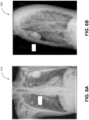
- a simulated three-dimensional representation of a subject's internal anatomy may be determined based on one or more two-dimensional images of the subject's internal anatomy. For example, a simulated three-dimensional representation corresponding to the subject's internal anatomy may be identified based on one or more two-dimensional images of the subject's internal anatomy (e.g. Figures 6A and 6B ).
- the two-dimensional images of the subject's internal anatomy may be obtained using a projectional radiography technique including, for example, X-rays, gamma ray imaging (e.g. bone scintigraphy), fluoroscopy, and/or the like.
- the simulated three-dimensional representation may be part of a library of simulated three-dimensional representations, each of which being associated with one or more corresponding two-dimensional images.
- one or more simulated radiograph images e.g., X-ray images, gamma ray images, and/or the like
- identifying the simulated three-dimensional representation corresponding to the subject's intemal anatomy may include matching the two-dimensional images of the subject's internal anatomy to the computed two-dimensional images associated with the simulated three-dimensional representation.
- the library of simulated three-dimensional representations includes one or more existing three-dimensional representations of the internal anatomies of one or more reference subjects including, for example, computed tomography scans, magnetic resonance imaging scans, and/or the like.
- the reference subjects may exhibit a variety of different anatomical attributes including, for example, variations in skeletal properties (e.g., size, abnormalities, and/or the like), organ geometry (e.g., size, relative position, and/or the like), musculature, subcutaneous fat distribution, and/or the like.
- the simulated three-dimensional representations included in the library may also depict a variety of different anatomical attributes.
- additional anatomical variations may be introduced into the library of simulated three-dimensional representations by at least generating, based on the existing three-dimensional representations, one or more simulated three-dimensional representations that include at least variation to the internal anatomy of the corresponding reference subject.
- a muscle e.g. the pectoralis major muscle
- the muscle e.g. the pectoralis major muscle
- the muscle may be 10 mm in thickness.
- one or more additional simulated three-dimensional representations may be generated to include variations in the skeletal properties (e.g., size, abnormalities, and/or the like), organ geometries (e.g., size, relative position, and/or the like), musculature, and/or subcutaneous fat distribution of the same reference subject.
- variations in the skeletal properties e.g., size, abnormalities, and/or the like
- organ geometries e.g., size, relative position, and/or the like
- musculature e.g., subcutaneous fat distribution of the same reference subject.
- Each simulated three-dimensional representation included in the library may be associated with one or more computed two-dimensional images including, for example, X-ray images, gamma ray images, and/or the like.
- a computed two-dimensional image may be generated based at least on either (a) a density and/or radiation transmissivity of the different tissues forming each of the anatomical structures (e.g., organs) included in a corresponding simulated three-dimensional representation, or (b) the absorption rate of radiopharmaceuticals (e.g. technetium (99mTc) medronic acid and/or the like) by different tissues and the emission rate of the radiopharmaceutical.
- radiopharmaceuticals e.g. technetium (99mTc) medronic acid and/or the like
- Blender Blender Foundation, Amsterdam, Netherlands.
- a 3-dimensional model of the body may be loaded into Blender. Different tissues within the model may be assigned different light transmissivities (e.g. greater transmissivity for subcutaneous fat, less transmissivity for bone).
- a simulated light source may be placed on one side of the model, and a flat surface placed on the other side of the model. The transmission of light through the model is computed, and an image of the projection on the two dimensional surface is recorded. This image may be further manipulated (e.g. white-black inversion) to produce a simulated 2-dimensional radiograph.
- the simulated three-dimensional representation corresponding to the subject's internal anatomy may be identified by least matching the two-dimensional images of the subject's internal anatomy to computed two-dimensional images associated with the simulated three-dimensional representation.
- each of the simulated three-dimensional representation and the corresponding computed two-dimensional images included in the library may be associated with a diagnosis.
- a diagnosis for the subject may be determined based on the diagnosis that is associated with the computed two-dimensional images. For example, the subject may be determined to have dilated cardiomyopathy if the two-dimensional images of the subject is matched to the computed two-dimensional images associated with dilated cardiomyopathy.
- a two-dimensional image of the subject may be matched to one or more computed two-dimensional images by applying a variety of image comparison techniques including, for example, scale invariant feature transform (SIFT), speed up robust feature (SURF), binary robust independent elementary features (BRIEF), oriented FAST and rotated BRIEF (ORB), and/or the like.
- SIFT scale invariant feature transform
- SURF speed up robust feature
- BRIEF binary robust independent elementary features
- ORB oriented FAST and rotated BRIEF
- a match between a two-dimensional image of the subject and one or more computed two-dimensional images may further be determined by applying one or more machine learning-based image comparison techniques including, for example, autoencoders, neural networks, and/or the like.
- the match between a two-dimensional image of the subject's internal anatomy and one or more computed two-dimensional images may be probabilistic. For example, when a two-dimensional image of the subject is matched to computed two-dimensional images, each of the computed two-dimensional images may be associated with a value (e.g., a similarity index and/or the like) indicating a closeness of the match between the two-dimensional image and the computed two-dimensional image. Moreover, multiple diagnosis, including a likelihood for each of the diagnosis, may be determined for the subject based on the diagnosis associated with each of the computed two-dimensional images.
- a value e.g., a similarity index and/or the like
- the diagnosis for the subject may include a first probability (e.g., an x-percentage likelihood) of the subject having dilated cardiomyopathy and a second probability (e.g., an x-percentage likelihood) of the subject having a pulmonary embolism based at least on the probabilistic match between the two-dimensional images of the subject and the computed two-dimensional images included in the library.
- a first probability e.g., an x-percentage likelihood
- a second probability e.g., an x-percentage likelihood
- the electrical activities of an organ are typically measured by recording device having one more leads (e.g., pairs of electrodes measuring voltage changes), which may be placed on a surface of the body near the organ as in the case of electrocardiography (ECG) for measuring the electrical activities of the heart and electroencephalography (EEG) for measuring the electrical activities of the brain.
- ECG electrocardiography
- EEG electroencephalography
- surface recordings are associated with a number of limitations.
- surface recordings e.g., electrocardiography, electroencephalography, and/or the like
- surface recordings are performed under the assumption of a standard surface electrogram setup (e.g., lead placement) even though variations in actual lead position can alter the morphology of the resulting electrogram and/or vectorgram (e.g., electrocardiogram, electroencephalogram, vectorcardiogram, and/or the like).
- the morphology of the resulting electrogram can also be altered due to significant variations in individual anatomy (e.g. obesity and/or the like) and/or the presence of co-morbidities (e.g. the lung disease emphysema and/or the like), which vary the conduction of electrical signals through the body.
- a subject-specific computational simulation environment that captures individual variations in body surface lead placement and subject anatomy may enable a more accurate calculation of the electrical activity of the organ (e.g. heart, brain, and/or the like).
- a customized computational simulation environment for a subject may be generated to include a three-dimensional representation of the internal anatomy (e.g. thoracic anatomy including the heart for measuring cardiac electrical activity) as described above.
- each lead of a recording device may be determined based on one or more two-dimensional images of the subject's internal anatomy. Based on the simulated electrical activities of the organ and the known locations for the leads on the surface of the subject's body, an output for the simulated recording device (e.g., the electrical signals that are detected at each electrogram lead) may be determined based on the corresponding simulated three-dimensional representation of the subject's internal anatomy to generate a simulated electrogram (e.g. a simulated electrocardiogram, a simulated electroencephalogram, and/or the like).
- a simulated electrogram e.g. a simulated electrocardiogram, a simulated electroencephalogram, and/or the like.
- the relationship between each lead and the likely electrical activation pattern of the organ can be more accurately calculated.
- the relationship between the simulated organ and the simulated electrogram properties may enable the generation of a subject-specific transformation matrix, or correction matrix, that accounts for variations in lead placement and subject anatomy.
- the accuracy of the simulation algorithm applied to generate the simulated output may be improved by at least updating the simulation algorithm based on clinical data including actual measurements of the electrical activities of the subject's organ as measured from the body surface electrodes.
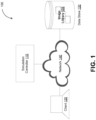
- the simulation controller 110 may be configured to identify, based at least on one or more two-dimensional images of the subject's internal anatomy, a simulated three-dimensional representation in the image library 135 that corresponds to the subject's internal anatomy.
- the simulation controller 110 may receive, from the client 120, on or more two-dimensional images of the subject's internal anatomy, which may be generated using a projectional radiography technique including, for example, X-rays, gamma rays, fluoroscopy, thermography, and/or the like.
- the simulation controller 110 may identify the simulated three-dimensional representation as corresponding to the subject's internal anatomy based at least on the two-dimensional images of the subject's internal anatomy being matched with the computed two-dimensional images associated with the simulated three-dimensional representation.
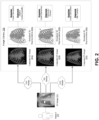
- FIG. 2 depicts a block diagram illustrating an example of identifying a simulated three-dimensional representation corresponding to a subject's internal anatomy, in accordance with some example embodiments.
- the simulation controller 110 may receive, from the client 120, one or more two-dimensional images depicting an internal anatomy of a subject 210 including, for example, a two-dimensional image 215.
- the two-dimensional image 215 may be generated using a projectional radiography technique including, for example, X-rays, gamma rays, fluoroscopy, and/or the like.
- the simulation controller 110 may identify, based at least on the two-dimensional image 215, one or more simulated three-dimensional representations in the image library 135 that corresponds to the internal anatomy of the subject 210.
- the image library 135 may include a plurality of simulated three-dimensional representations including, for example, a first simulated three-dimensional representation 220a, a second simulated three-dimensional representation 220b, a third simulated three-dimensional representation 220c, and/or the like. As shown in FIG. 2 , each simulated three-dimensional representation included in the image library 135 may be associated with one or more computed two-dimensional images, each of which being generated based on a corresponding simulated three-dimensional representation. For example, FIG.
- FIG. 2 shows the first simulated three-dimensional representation 220a being associated with a first computed two-dimensional image 225a generated based on the first simulated three-dimensional representation 220a, the second simulated three-dimensional representation 220b being associated with a second computed two-dimensional image 225b generated based on the second simulated three-dimensional representation 220b, and the third simulated three-dimensional representation 220c being associated with a third computed two-dimensional image 225c generated based on the third simulated three-dimensional representation 220c.
- the simulation controller 110 may apply one or more image comparison techniques in order to determine whether the two-dimensional image 215 matches the first computed two-dimensional image 225a associated with the first simulated three-dimensional representation 220a, the second computed two-dimensional image 225b associated with the second simulated three-dimensional representation 220b, and/or the third computed two-dimensional image 225c associated with the third simulated three-dimensional representation 220c.
- the one or more image comparison techniques may include scale invariant feature transform (SIFT), speed up robust feature (SURF), binary robust independent elementary features (BRIEF), oriented FAST and rotated BRIEF (ORB), and/or the like.
- the one or more image comparison techniques may include one or more machine learning models trained to identify similar images including, for example, autoencoders, neural networks, and/or the like.
- the simulation controller 110 may determine that the first computed two-dimensional image 225a is 75% similar to the two-dimensional image 215, the second computed two-dimensional image 225b is 5% similar to the two-dimensional image 215, and the third computed two-dimensional image 225c is 55% similar to the two-dimensional image 215.
- the simulation controller 110 may determine, based at least on the respective similarity index, that one or more of the first computed two-dimensional image 225a, the second computed two-dimensional image 225b, and the third computed two-dimensional image 225c match the two-dimensional image 215.
- the simulation controller 110 may determine that the first computed two-dimensional image 225a matches the two-dimensional image 215 based on the first computed two-dimensional image 225a being associated with a highest similarity index and/or the first computed two-dimensional image 225a being associated with a similarity index exceeding a threshold value.
- each of the first simulated three-dimensional representation 220a, the second simulated three-dimensional representation 220b, and the third simulated three-dimensional representation 220c may be associated with a diagnosis.
- the simulation controller 110 may further determine one or more diagnosis for the subject 210 based at least on the one or more simulated three-dimensional representations determined to correspond to the internal anatomy of the subject 210.
- each diagnosis may be associated with a probability corresponding to the similarity index between the two-dimensional image 215 and the computed two-dimensional image matched with the two-dimensional image 215.
- the simulation controller 110 may determine that there is a 75% chance of the subject 210 being afflicted with dilated cardiomyopathy.
- the simulation controller 110 may determine that there is a 5% chance of the subject 210 being afflicted with a pulmonary embolism.
- an actual diagnosis for the subject 210 may be used to at least refine one or more machine learning-based image comparison techniques for matching the two-dimensional image 215 to one or more of the first computed two-dimensional image 225a, the second computed two-dimensional image 225b, and the third computed two-dimensional image 225c.
- the simulation controller 110 may at least retrain the machine learning model to correctly match the two-dimensional image 215 to the third computed two-dimensional image 225c.
- the machine learning model may be retrained based on additional training data that include at least some two-dimensional images that depict a rib fracture.
- the retraining of the machine learning model may include further updating the one or more weights and/or biases applied by the machine learning model to reduce an error in an output of the machine learning model including, for example, the mismatching of two-dimensional images depicting rib fractures.
- the computed two-dimensional images (and the corresponding simulated three-dimensional representations) included in the image library 135 may be indexed based on the corresponding primary symptom and/or complaint of the subject.
- the first computed two-dimensional image 225a, the second computed two-dimensional image 225b, and the third computed two-dimensional image 225c may be indexed based on the complaint or symptom of "chest discomfort.”
- the computed two-dimensional images (and the corresponding simulated three-dimensional representations) included in the image library 135 may be indexed based on the corresponding diagnosis and/or types of diagnosis. For instance, the first computed two-dimensional image 225a and the second computed two-dimensional image 225b may be indexed as "heart conditions" while the third computed two-dimensional image 225c may be indexed as "bone fractures.”
- the simulation controller 110 may eliminate, based on the demographics and/or the vital statistics of the subject 210, one or more computed two-dimensional images of reference subjects having different demographics and/or vital statistics than the subject 210. Alternatively and/or additionally, the simulation controller 110 may further eliminate, based on one or more symptoms of the subject 210, one or more computed two-dimensional images associated with diagnosis that are inconsistent with the symptoms of the subject 210.
- the reference subjects may exhibit a variety of different anatomical attributes including, for example, variations in skeletal properties (e.g., size, abnormalities, and/or the like), organ geometry (e.g., size, relative position, and/or the like), musculature, subcutaneous fat distribution, and/or the like.
- variations in skeletal properties e.g., size, abnormalities, and/or the like
- organ geometry e.g., size, relative position, and/or the like
- musculature e.g., subcutaneous fat distribution, and/or the like.
- the first simulated three-dimensional representation 220a, the second simulated three-dimensional representation 220b, and/or the third simulated three-dimensional representation 220c may also depict a variety of different anatomical attributes.
- additional anatomical variations may be introduced computationally into the image library 135 by at least generating, based on the existing three-dimensional representations, one or more simulated three-dimensional representations that include at least variation to the internal anatomy of the corresponding reference subject.
- the first simulated three-dimensional representation 220a, the second simulated three-dimensional representation 220b, and/or the third simulated three-dimensional representation 220c may be generated, based on one or more existing three-dimensional representations of the internal anatomy of a reference subject, to include variations in the skeletal properties (e.g., size, abnormalities, and/or the like), organ geometries (e.g., size, relative position, and/or the like), musculature, and/or subcutaneous fat distribution of the same reference subject.
- skeletal properties e.g., size, abnormalities, and/or the like
- organ geometries e.g., size, relative position, and/or the like
- musculature e.g., subcutaneous fat distribution of the same reference subject.
- FIGS. 3A-C and 4A-C depicts examples of simulated three-dimensional representations of internal anatomies, in accordance with some example embodiments.
- FIGS. 3A-C and 4A-C depict examples of simulated three-dimensional representations that may be generated based on existing three-dimensional representations of the internal anatomies of one or more reference subjects including, for example, computed tomography scans, magnetic resonance imaging scans, and/or the like.
- FIGS. 3A-C and 4A-C depict examples of simulated three-dimensional representations that may be generated based on existing three-dimensional representations of the internal anatomies of one or more reference subjects including, for example, computed tomography scans, magnetic resonance imaging scans, and/or the like.
- 3A-C and 4A-C depict examples of simulated three-dimensional representations with computationally introduced anatomical variations including, for example, variations in skeletal properties (e.g., size, abnormalities, and/or the like), organ geometries (e.g., size, relative position, and/or the like), musculature, subcutaneous fat distribution, and/or the like.
- variations in skeletal properties e.g., size, abnormalities, and/or the like
- organ geometries e.g., size, relative position, and/or the like
- musculature e.g., subcutaneous fat distribution, and/or the like.
- FIG. 3A-C depict examples of simulated three-dimensional representations of skeletal anatomy, in accordance with some example embodiments.
- FIG. 3A may depict a simulated three-dimensional representation 310 of the skeletal anatomy of a first reference subject who is a 65 years old, male, 6 feet 5 inches tall, weighing 220 pounds, and having severe congestive heart failure with a left ventricular ejection fraction of 25%.
- FIG. 3B may depict a simulated three-dimensional representation 320 of the skeletal anatomy of a second reference subject who is 70 years old, female, 5 feet 7 inches tall, weighing 140 pounds, and having moderate chronic systolic congestive heart failure with a left ventricular ejection fraction of 35%.
- FIG. 3A may depict a simulated three-dimensional representation 310 of the skeletal anatomy of a first reference subject who is a 65 years old, male, 6 feet 5 inches tall, weighing 220 pounds, and having severe congestive heart failure with a left ventricular ejection fraction of 25%.
- FIG. 3C may depict a simulated three-dimensional representation 330 of the skeletal anatomy of a third reference subject who is 18 years old, weighing 120 pounds, and having a congenital heart disease with an ejection fraction of 45%.
- FIG. 3A-C may be indexed based on one or more attributes including, for example, the demographics (e.g., age, gender, and/or the like), the vital statistics (e.g., weight, height, and/or the like), and/or the condition of the corresponding reference subject.
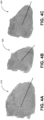
- FIGS. 4A-C depicts examples of simulated three-dimensional representations of cardiac anatomies, in accordance with some example embodiments.
- FIG. 4A depicts a simulated three-dimensional representation 410 of a heart with moderate congestive heart failure, an ejection fraction of 40%, and a ventricular axis of 30 degrees (shown as a black line) in the frontal plane.
- FIG. 4B depicts a simulated three-dimensional representation 420 of a heart with a normal ejection fraction of 57% and a ventricular axis of 45 degrees (shown as a black line) in the frontal plane.
- FIG. 4A depicts a simulated three-dimensional representation 410 of a heart with moderate congestive heart failure, an ejection fraction of 40%, and a ventricular axis of 30 degrees (shown as a black line) in the frontal plane.
- FIG. 4B depicts a simulated three-dimensional representation 420 of a heart with a normal ejection fraction of 57% and
- FIGS. 4A-C depicts a simulated three-dimensional representation 420 of a heart with severe left ventricular dysfunction, an ejection fraction of 20%, and a ventricular axis of 20 degrees (shown as a black line) in the frontal plane.
- FIGS. 4A-C may also be indexed based on one or more attributes including, for example, the demographics (e.g., age, gender, and/or the like), the vital statistics (e.g., weight, height, and/or the like), and/or the condition of the corresponding reference subject.
- the computed two-dimensional images included in the image library 135 may correspond to radiograph images (e.g., X-ray images, gamma ray images, fluoroscopy images, and/or the like), which are typically captured using a projectional, or 2-dimensional radiography techniques, in which at least a portion of a subject is exposed to electromagnetic radiation (e.g., X-rays, gamma rays, and/or the like).
- a computed two-dimensional image may be generated by at least simulating the effects of being exposed to a radiation source. For example, the computed two-dimensional image based at least on a density and/or radiation transmissivity of the different tissues included in the simulated three-dimensional representation.
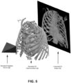
- FIG. 5 depicts an example of a technique for generating a computed two-dimensional image, in accordance with some example embodiments.
- a computed two-dimensional image 510 may be generated (e.g. using the software Blender (Blender Foundation, Amsterdam, Netherlands)) by at least simulating the effects of exposing, to a simulated radiation source 520 (e.g. light), a simulated three-dimensional representation 530 of an internal anatomy (e.g., a thoracic cavity and/or the like).
- a simulated radiation source 520 e.g. light
- a simulated three-dimensional representation 530 of an internal anatomy e.g., a thoracic cavity and/or the like.
- the computed two-dimensional image 510 may be generated by at least determining, based at least on a density and/or transmissivity of the different tissues included in the simulated three-dimensional representation 530, a quantity of simulated radiation (e.g., from the simulated radiation source 520) that is able to pass through the different tissues included in the simulated three-dimensional representation 530 onto a simulated surface.
- An image of this project is then recorded and further processed (e.g. white-black inversion) to form the computed two-dimensional image 510.
- a view of the simulated three-dimensional representation 530 (e.g., straight anterior-posterior, anterior oblique, and/or the like) that is captured in the computed two-dimensional image 510 may be varied by at least varying a position and/or an orientation of the simulated radiation source 520 relative of the simulated three-dimensional representation 530. Accordingly, multiple computed two-dimensional image may be generated for each simulated three-dimensional representation in order to capture different views of the simulated three-dimensional representation including, for example, a left anterior oblique view, a right anterior oblique view, a straight anterior-posterior view, and/or the like.
- FIG. 6B depicts another example of a clinical two-dimensional image 620 showing a left lateral view of the same subject. Again, the positions of several surface electrodes may also be observed in the clinical two-dimensional image 620.
- FIG. 7 depicts an example of leads for measuring the electrical activities of the heart.
- a plurality of leads e.g., V1, V2, V3, V4, V5, and V6 may be placed on the surface of the subject's skin.
- Each of the plurality of leads may be configured to measure a voltage change on the surface of the subject's skin that corresponds to the electrical activities of the subject's heart including, for example, the dipole that is created due to the successive depolarization and repolarization of the heart.
- the signal from each lead may be recorded, in combination with one or more other leads, to generate, for example, the electrocardiogram 800 shown in FIG. 8 , demonstrating normal sinus rhythm.
- FIG. 9A depicts a flowchart illustrating an example of an imaging process 900, in accordance with some example embodiments.
- the process 900 may be performed by the simulation controller 110.
- the simulation controller 110 may perform the imaging process 900 in order to generate a three-dimensional representation of an internal anatomy of the subject 210 by at least identifying a simulated three-dimensional representation in the image library 135 that corresponds to the internal anatomy of the subject 210.
- the imaging process 900 may be performed to determine, based on the simulated three-dimensional representation corresponding to the internal anatomy of the subject 210, a diagnosis for the subject 210.
- the simulation controller 100 may perform the imaging process 900 in order to simulate the electrical activities of one or more organs of the subject 210.
- the simulation controller 110 may generate an image library including a plurality of simulated three-dimensional representations of internal anatomies that are each associated with a diagnosis and one or more computed two-dimensional images.
- the image library 135 may include a plurality of simulated three-dimensional representations including, for example, the first simulated three-dimensional representation 220a, the second simulated three-dimensional representation 220b, the third simulated three-dimensional representation 220c, and/or the like.
- the first simulated three-dimensional representation 220a, the second simulated three-dimensional representation 220b, and/or the third simulated three-dimensional representation 220c may also depict a variety of different anatomical attributes.
- the first simulated three-dimensional representation 220a, the second simulated three-dimensional representation 220b, and/or the third simulated three-dimensional representation 220c may be existing three-dimensional representations of the internal anatomies of one or more reference subjects exhibiting a variety of different anatomical attributes including, for example, variations in skeletal properties (e.g., size, abnormalities, and/or the like), organ geometry (e.g., size, relative position, and/or the like), musculature, subcutaneous fat distribution, and/or the like.
- one or more anatomical variations may be introduced computationally into the first simulated three-dimensional representation 220a, the second simulated three-dimensional representation 220b, and/or the third simulated three-dimensional representation 220c.
- the simulated three-dimensional representations included in the image library 135 may be used to generate the computed two-dimensional images included in the image library 135.
- the first computed two-dimensional image 225a may be generated based on the first simulated three-dimensional representation 220a
- the second computed two-dimensional image 225b may be generated based on the second simulated three-dimensional representation 220b
- the third computed two-dimensional image 225c may be generated based on the third simulated three-dimensional representation 220c.
- the first computed two-dimensional image 225a, the second computed two-dimensional image 225b, and the third computed two-dimensional image 225c may each be generated by exposing, to a simulated radiation source, the corresponding first simulated three-dimensional representation 220a, the second simulated three-dimensional representation 220b, and the third simulated three-dimensional representation 220c.
- each of the simulated three-dimensional representations and the corresponding computed two-dimensional images included in the image library 135 may be associated with a primary symptom or complaint as well as a diagnosis.
- the first computed two-dimensional image 225a, the second computed two-dimensional image 225b, and the third computed two-dimensional image 225c may be associated with the complaint or symptom of "chest discomfort.”
- the first simulated three-dimensional representation 220a (and the first computed two-dimensional image 225a) may be associated with a diagnosis of dilated cardiomyopathy
- the second simulated three-dimensional representation 220b (and the second computed two-dimensional image 225b) may be associated with a diagnosis of a pulmonary embolism
- the third simulated three-dimensional representation 220c (and the third computed two-dimensional image 225c) may be associated with a diagnosis of a rib fracture.
- the one or more image comparison techniques may include scale invariant feature transform (SIFT), speed up robust feature (SURF), binary robust independent elementary features (BRIEF), oriented FAST and rotated BRIEF (ORB), and/or the like.
- SIFT scale invariant feature transform
- SURF speed up robust feature
- BRIEF binary robust independent elementary features
- ORB rotated BRIEF
- the one or more image comparison techniques may include one or more machine learning models trained to identify similar images including, for example, autoencoders, neural networks, and/or the like.
- the simulation controller 110 may determine, based at least on a computed two-dimensional image having a highest similarity index and/or a similarity index exceeding a threshold value, that one or more of the first computed two-dimensional image 225a, the second computed two-dimensional image 225b, and the third computed two-dimensional image 225c match the two-dimensional image 215.
- the time and computation resources associated with searching the image library 135 for one or more computed two-dimensional images matching the two-dimensional image 215 may be reduced by applying one or more filters to eliminate at least some of the computed two-dimensional images from the search.
- the computed two-dimensional images (and the corresponding simulated three-dimensional representations) included in the image library 135 may be indexed based on one or more attributes such as, for example, the demographics (e.g., age, gender, and/or the like) and/or the vital statistics (e.g., height, weight, and/or the like) of reference subjects depicted in the computed two-dimensional image.
- the computed two-dimensional images (and the corresponding simulated three-dimensional representations) included in the image library 135 may be indexed based on the corresponding diagnosis and/or types of diagnosis.
- the simulation controller 110 may eliminate, based on the demographics, the vital statistics, and/or the symptoms of the subject 210, one or more computed two-dimensional images of reference subjects having different demographics, different vital statistics, and/or diagnosis that are inconsistent with the symptoms of the subject 210.
- the image library 315 may exclude, from the search of the image library 135, the third computed two-dimensional image 225c based at least on the third computed two-dimensional image 225c being associated with a diagnosis (e.g., rib fracture) that is inconsistent with the symptoms of the subject 210.
- the simulation controller 110 may generate a first output including the simulated three-dimensional representation corresponding to the internal anatomy of the subject and/or a diagnosis associated with the simulated three-dimensional representation. For example, in response to the two-dimensional image 215 of the subject 210 being matched to the first computed two-dimensional image 225a, the simulation controller 110 may generate an output including the first simulated three-dimensional representation 220a and/or the diagnosis (e.g., dilated cardiomyopathy) associated with the first simulated three-dimensional representation 220a. The simulation controller 110 may generate the output to also include a value indicative of the closeness of the match (e.g., 75% similar) between the two-dimensional image 215 and the first computed two-dimensional image 225a. Alternatively and/or additionally, the simulation controller 110 may generate the output to include a value indicative of a probability of the diagnosis associated with the first simulated three-dimensional representation 220a (e.g., 75% chance of dilated cardiomyopathy).
- the simulation controller 110 may send, to the client 120, the first output including the simulated three-dimensional representation corresponding to the internal anatomy of the subject and/or a diagnosis associated with the simulated three-dimensional representation.
- the simulation controller 110 may generate a user interface configured to display, at the client 120, the first output including the simulated three-dimensional representation corresponding to the internal anatomy of the subject and/or a diagnosis associated with the simulated three-dimensional representation.
- the simulation controller 110 may determine, based at least on one or more clinical two-dimensional images of the subject and the simulated three-dimensional representation corresponding to the internal anatomy of the subject, a lead placement for a recording device measuring an electrical activity of an organ of the subject.
- a lead placement for electrocardiography (ECG) to measure the electrical activities of the heart and/or electroencephalography (EEG) to measure the electrical activities of the brain may be determined based on the images 610 and 620 corresponding to figure 9C and 9D .
- the simulation controller 110 may generate, based at least on the lead placement and the simulated three-dimensional representation corresponding to the internal anatomy of the subject, a second output including the lead placement and a simulation of the electrical activities measured by the recording device. For example, in some example embodiments, the simulation controller 110 may further determine, based at least on the lead placement (e.g., determined at operation 908) and the first simulated three-dimensional representation 220a corresponding to the internal anatomy of the subject 210, a simulated electrocardiogram (ECG) depicting the electrical activities of the heart and/or a simulated electroencephalography (EEG) depicting the electrical activities of the brain.
- ECG electrocardiogram
- EEG simulated electroencephalography
- the simulation controller 110 may send, to the client 120, the second output including the lead placement and/or the simulation of the electrical activities measured by the recording device.
- the simulation controller 110 may generate a user interface configured to display, at the client 120, the second output including the lead placement and/or the simulation of the electrical activities measured by the recording device.
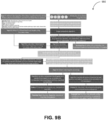
- FIG. 9B depicts a flowchart illustrating another example of an imaging process 950, in accordance with some example embodiments.
- the process 950 may be performed by the simulation controller 110.
- the simulation controller 110 may perform the imaging process 950 in order to generate a three-dimensional representation of an internal anatomy of the subject 210 by at least identifying a simulated three-dimensional representation in the image library 135 that corresponds to the internal anatomy of the subject 210.
- the imaging process 950 may be performed to determine, based on the simulated three-dimensional representation corresponding to the internal anatomy of the subject 210, a diagnosis for the subject 210.
- the simulation controller 110 may receive inputs including (1) demographic and clinical information such as age, weight, sex, clinical situation, and symptoms; (2) two-dimensional clinical images from one or more views (examples include figures 6A and 6B ); and (3) subject electrical recordings (e.g. a clinical electrogram or vectorgram such as, for example, a clinical electrocardiogram, electroencephalogram, vectorcardiogram, and/or the like).
- demographic and clinical information such as age, weight, sex, clinical situation, and symptoms
- two-dimensional clinical images from one or more views examples include figures 6A and 6B
- subject electrical recordings e.g. a clinical electrogram or vectorgram such as, for example, a clinical electrocardiogram, electroencephalogram, vectorcardiogram, and/or the like.
- the image library 135 may be created from subject-derived, three-dimensional representations of subject anatomy.
- the simulated two-dimensional images may be created to include simulated two-dimensional images from different angles.
- the simulated two-dimensional images and the corresponding three-dimensional models may be indexed with one or more subject attributes including, for example, weight, height, sex, clinical situation, symptoms, and/or the like.
- the simulation controller may receive inputs including, for example, the subject's age, weight, height, sex, clinical situation, and symptoms ( FIG. 9B , Input 1).
- the simulation controller 110 may select an appropriate simulation library ( FIG. 9B , face symbol) for the intended instance ( FIG 9B , Intermediate Product 1).
- the simulation controller 110 may receive one or more two-dimensional images of the subject's anatomy ( FIG. 9B , Input 2) and compares these two-dimensional images to the computed two-dimensional images included in the image library 135. Computed two-dimensional images with the highest correlation with the subject's two-dimensional images may be identified.
- a combination of the highest matching computed two-dimensional images, the corresponding three-dimensional representations, and the associated case information may be output by the simulation controller 110 ( FIG. 9B , Product 1).
- a simulation of the electrical activation of the organ may be performed within the subject-specific three-dimensional simulation environment including the three-dimensional representation corresponding to the subject's internal anatomy.
- the simulated electrical field from the organ may be calculated as the electrical field diffuses through body tissues to the skin surface.
- Simulated recordings at both the subject-specific electrode positions and standard electrode positions may be computed.
- the relationship between the organ's electrical activation and the body surface recordings may be used to compute correction function for each electrode site (e.g. a "nonstandard-to-standard correction matrix") and for correcting between the organ's electrical activation pattern and that observed at the body surface (e.g. a "vectorgram correction matrix").
- the simulation controller 110 may operate (1) to create a simulated three-dimensional representation of a subject's internal anatomy as well as a computational assessment of diagnosis probability ( FIG. 9B : Potential Use 1); (2) to convert a nonstandard electrogram (e.g. nonstandard 12-lead electrocardiogram) to a standard electrogram (e.g. standard 12-lead electrocardiogram) ( FIG. 9B : Potential Use 2) to improve the diagnostic accuracy of the electrogram; and (3) to correct for subject-specific variations in electrode position and subject anatomy in the calculation of a three-dimensional vectorgram (e.g., vectorcardiogram and/or the like) to permit an accurate electrical source mapping (e.g. for use in arrhythmia source localization) ( FIG. 9B , Potential Use 3).
- a nonstandard electrogram e.g. nonstandard 12-lead electrocardiogram
- a standard electrogram e.g. standard 12-lead electrocardiogram
- FIG. 9B Potential Use 2
- FIG. 9B Potential Use 2
- FIG. 9B Potential Use 2
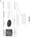
- FIG. 9C depicts a block diagram illustrating an example of process 960 for generating a corrected electrogram, in accordance with some example embodiments.
- the process 960 may be performed by the simulation controller 110 in order to generate a corrected electrogram that accounts for variations in lead placement and subject anatomy.
- the simulation controller 110 may generate, based at least on a simulated three-dimensional representation of the subject's internal anatomy (e.g., thorax cavity and/or the like), a rhythm simulation (e.g., ventricular tachycardia and/or the like).
- the simulated three-dimensional representation of the subject's internal anatomy may be identified based on one or more clinical two-dimensional images of the subject's internal anatomy.
- a first plurality of surface electrode recordings may be computed based on the rhythm simulation to account for subject-specific lead placements, which may deviate from standard lead placements.
- a second plurality of surface electrode recordings corresponding to standard lead placements may also be computed based on the rhythm simulation.
- a transformation matrix A may be generated based on a difference between the first plurality of surface electrode recordings and the second plurality of surface electrode recordings.
- the transformation matrix A may capture variations in lead placement as well as subject anatomy. Accordingly, the transformation matrix A may be applied to a clinical electrogram (e.g., a clinical electrocardiogram, a clinical electroencephalogram, and/or the like) to generate a corrected electrogram (e.g., a corrected electrogram, a corrected electroencephalogram, and/or the like) by at least removing, from the clinical electrogram, deviations that are introduced by non-standard lead placement and/or anatomical variations.
- a clinical electrogram e.g., a clinical electrocardiogram, a clinical electroencephalogram, and/or the like
- a corrected electrogram e.g., a corrected electrogram, a corrected electroencephalogram, and/or the like
- a transformation matrix A may be generated based on a difference between the simulated three-dimensional electrical properties of the target organ and the simulated body surface recordings.
- the transformation matrix A may capture variations in lead placement as well as subject anatomy. Accordingly, the transformation matrix A may be applied to a clinical vectorgram (e.g., a clinical vectorcardiogram and/or the like) to generate a corrected vectorgram (e.g., a corrected vectorcardiogram and/or the like) by at least removing, from the clinical vectorcardiogram, deviations arising from non-standard lead placement and/or anatomical variations.
- FIG. 10 depicts a block diagram illustrating a computing system 1000, in accordance with some example embodiments.
- the computing system 1000 can be used to implement the simulation controller 110 and/or any components therein.
- the computing system 1000 can include a processor 1010, a memory 1020, a storage device 1030, and input/output device 1040.
- the processor 1010, the memory 1020, the storage device 1030, and the input/output device 1040 can be interconnected via a system bus 1050.
- the processor 1010 is capable of processing instructions for execution within the computing system 1000. Such executed instructions can implement one or more components of, for example, the simulation controller 110.
- the processor 1010 can be a single-threaded processor. Alternately, the processor 1010 can be a multi-threaded processor.
- the processor 1010 is capable of processing instructions stored in the memory 1020 and/or on the storage device 1030 to display graphical information for a user interface provided via the input/output device 1040.
- the memory 1020 is a computer readable medium such as volatile or nonvolatile that stores information within the computing system 1000.
- the memory 1020 can store data structures representing configuration object databases, for example.
- the storage device 1030 is capable of providing persistent storage for the computing system 1000.
- the storage device 1030 can be a floppy disk device, a hard disk device, an optical disk device, or a tape device, or other suitable persistent storage means.
- the input/output device 1040 provides input/output operations for the computing system 1000.
- the input/output device 1040 includes a keyboard and/or pointing device.
- the input/output device 1040 includes a display unit for displaying graphical user interfaces.
- the input/output device 1040 can provide input/output operations for a network device.
- the input/output device 1040 can include Ethernet ports or other networking ports to communicate with one or more wired and/or wireless networks (e.g., a local area network (LAN), a wide area network (WAN), the Internet).
- LAN local area network
- WAN wide area network
- the Internet the Internet
- the computing system 1000 can be used to execute various interactive computer software applications that can be used for organization, analysis and/or storage of data in various (e.g., tabular) format.
- the computing system 1000 can be used to execute any type of software applications.
- These applications can be used to perform various functionalities, e.g., planning functionalities (e.g., generating, managing, editing of spreadsheet documents, word processing documents, and/or any other objects, etc.), computing functionalities, communications functionalities, and/or the like.
- the applications can include various add-in functionalities or can be standalone computing products and/or functionalities.
- the functionalities can be used to generate the user interface provided via the input/output device 1040.
- the user interface can be generated and presented to a user by the computing system 1000 (e.g., on a computer screen monitor, etc.).
- One or more aspects or features of the subject matter described herein can be realized in digital electronic circuitry, integrated circuitry, specially designed application specific integrated circuits (ASICs), field programmable gate arrays (FPGAs) computer hardware, firmware, software, and/or combinations thereof.
- ASICs application specific integrated circuits
- FPGAs field programmable gate arrays
- These various aspects or features can include implementation in one or more computer programs that are executable and/or interpretable on a programmable system including at least one programmable processor, which can be special or general purpose, coupled to receive data and instructions from, and to transmit data and instructions to, a storage system, at least one input device, and at least one output device.
- the programmable system or computing system may include clients and servers.
- a client and server are generally remote from each other and typically interact through a communication network. The relationship of client and server arises by virtue of computer programs running on the respective computers and having a client-server relationship to each other.
- machine-readable medium refers to any computer program product, apparatus and/or device, such as for example magnetic discs, optical disks, memory, and Programmable Logic Devices (PLDs), used to provide machine instructions and/or data to a programmable processor, including a machine-readable medium that receives machine instructions as a machine-readable signal.
- machine-readable signal refers to any signal used to provide machine instructions and/or data to a programmable processor.
Landscapes
- Health & Medical Sciences (AREA)
- Engineering & Computer Science (AREA)
- Life Sciences & Earth Sciences (AREA)
- Medical Informatics (AREA)
- Public Health (AREA)
- General Health & Medical Sciences (AREA)
- Biomedical Technology (AREA)
- Physics & Mathematics (AREA)
- Pathology (AREA)
- Veterinary Medicine (AREA)
- Biophysics (AREA)
- Heart & Thoracic Surgery (AREA)
- Molecular Biology (AREA)
- Surgery (AREA)
- Animal Behavior & Ethology (AREA)
- Nuclear Medicine, Radiotherapy & Molecular Imaging (AREA)
- Radiology & Medical Imaging (AREA)
- High Energy & Nuclear Physics (AREA)
- Optics & Photonics (AREA)
- Epidemiology (AREA)
- Primary Health Care (AREA)
- Data Mining & Analysis (AREA)
- Databases & Information Systems (AREA)
- Computer Vision & Pattern Recognition (AREA)
- Artificial Intelligence (AREA)
- Cardiology (AREA)
- Theoretical Computer Science (AREA)
- Human Computer Interaction (AREA)
- Oral & Maxillofacial Surgery (AREA)
- Dentistry (AREA)
- General Physics & Mathematics (AREA)
- Quality & Reliability (AREA)
- Signal Processing (AREA)
- Fuzzy Systems (AREA)
- Mathematical Physics (AREA)
- Physiology (AREA)
- Psychiatry (AREA)
- Orthopedic Medicine & Surgery (AREA)
- Evolutionary Computation (AREA)
- Pulmonology (AREA)
Claims (9)
- System (100; 1000), aufweisend:mindestens einen Prozessor (110; 1010); undmindestens einen Speicher (1020), der einen Programmcode enthält, der, wenn er von dem mindestens einen Prozessor (110; 1010) ausgeführt wird, Operationen bereitstellt, umfassend:Empfangen eines oder mehrerer zweidimensionaler Bilder (215, 620) von mindestens einem Abschnitt einer Anatomie eines Subjekts (210), das ein Zielorgan, wie z. B. das Herz eines Patienten, und eine oder mehrere Elektrodenableitungen (615a-c) umfasst, die an einem Körper des Subjekts (210) gemäß einer nicht standardmäßigen Ableitungsplatzierung bereitgestellt werden;Ermittlung einer dreidimensionalen Darstellung (220a-c) des Abschnitts der Anatomie des Subjekts (210) einschließlich des Zielorgans,wobei das Identifizieren das Vergleichen des zweidimensionalen Bildes (215, 620) mit einem oder mehreren zweidimensionalen Bildern (225a-c), die in einer Bibliothek (135) enthalten sind, umfasst, das Zuordnen des einen oder der mehreren zweidimensionalen Bilder (225a-c) zu einer oder mehreren entsprechenden dreidimensionalen Darstellungen (220a-c);Identifizieren der nicht standardmäßigen Ableitungsposition der einen oder mehreren Elektrogrammableitungen (615a-c) am Körper des Subjekts (210) auf Basis mindestens einer Analyse des zweidimensionalen Bildes (215, 620);Erstellen einer subjektspezifischen dreidimensionalen Simulationsumgebung einschließlich der dreidimensionalen Darstellung (220a-c) zum Simulieren elektrischer Aktivierungen des Zielorgans;Erzeugen einer oder mehrerer simulierter elektrischer Aktivierungen des Zielorgans auf Basis der patientenspezifischen dreidimensionalen Simulationsumgebung;Erzeugen eines Nicht-Standard-Elektrogramms auf Basis mindestens der einen oder mehreren simulierten elektrischen Aktivierungen, das mit der Nicht-Standard-Ableitungsplatzierung der einen oder mehreren Elektrogrammableitungen (615a-c) am Körper des Patienten (210) verbunden ist;Erzeugen, auf Basis mindestens einer oder mehrerer simulierter elektrischer Aktivierungen, eines Standardelektrogramms (800), das mit einer Standardableitungsplatzierung der einen oder mehreren Elektrogrammableitungen (615 a-c) am Körper des Probanden (210) verbunden ist; undKorrigieren, auf Basis zumindest einer Differenz zwischen dem nicht standardmäßigen Elektrogramm und dem Standardelektrogramm (800), eines tatsächlichen Elektrogramms, das für die Person (210) unter Verwendung der nicht standardmäßigen Ableitungsplatzierung erzeugt wird.
- System (100; 1000) nach Anspruch 1, wobei das Standardelektrogramm (800), das Nicht-Standardelektrogramm und das tatsächliche Elektrogramm Elektrokardiogramme, Elektroenzephalogramme oder Vektorkardiogramme umfassen.
- System (100; 1000) nach einem der Ansprüche 1 bis 2, wobei die Korrektur das Erzeugen einer Transformationsmatrix zum Umwandeln des nicht standardmäßigen Elektrogramms in das standardmäßige Elektrogramm und das Anwenden der Transformationsmatrix auf das tatsächliche Elektrogramm umfasst.
- System (100; 1000) nach einem der Ansprüche 1 bis 3, wobei die Vorgänge ferner Folgendes umfassen:Identifizieren eines simulierten Elektrogramms, das mit dem korrigierten Elektrogramm übereinstimmt, durch mindestensDurchsuchen einer Bibliothek (135), die eine Vielzahl simulierter Elektrogramme enthält, wobei die Bibliothek (135) die Vielzahl simulierter Elektrogramme auf eine oder mehrere Eigenschaften des Zielorgans abbildet, die zur Erzeugung der Vielzahl simulierter Elektrogramme verwendet werden.
- Computerimplementiertes Verfahren, aufweisend:Empfangen eines oder mehrerer zweidimensionaler Bilder (215, 620) von mindestens einem Abschnitt einer Anatomie eines Subjekts (210), das ein Zielorgan, wie z. B. das Herz eines Patienten, und eine oder mehrere Elektrodenableitungen (615a-c) umfasst, die an einem Körper des Subjekts (210) gemäß einer nicht standardmäßigen Ableitungsplatzierung bereitgestellt werden;Ermittlung einer dreidimensionalen Darstellung (220a-c) des Abschnitts der Anatomie des Subjekts (210) einschließlich des Zielorgans,wobei das Identifizieren das Vergleichen des zweidimensionalen Bildes (215, 620) mit einem oder mehreren zweidimensionalen Bildern (225a-c), die in einer Bibliothek (135) enthalten sind, das Zuordnen des einen oder der mehreren zweidimensionalen Bilder (225a-c) zu einer oder mehreren entsprechenden dreidimensionalen Darstellungen (220a-c) umfasst;Identifizieren der nicht standardmäßigen Ableitungsposition der einen oder mehreren Elektrogrammableitungen (615a-c) am Körper des Probanden (210) auf Basis mindestens einer Analyse des zweidimensionalen Bildes (215, 620);Erstellen einer probandenspezifischen dreidimensionalen Simulationsumgebung einschließlich der dreidimensionalen Darstellung (220a-c) zur Simulation elektrischer Aktivierungen des Zielorgans;Erzeugen einer oder mehrerer simulierter elektrischer Aktivierungen des Zielorgans auf Basis der patientenspezifischen dreidimensionalen Simulationsumgebung;Erzeugen eines nicht standardmäßigen Elektrogramms auf Basis mindestens der einen oder mehreren simulierten elektrischen Aktivierungen, das mit der nicht standardmäßigen Ableitungsplatzierung der einen oder mehreren Elektrogrammableitungen (615 a-c) am Körper des Patienten (210) verbunden ist;Erzeugen, auf Basis mindestens einer oder mehrerer simulierter elektrischer Aktivierungen, eines Standardelektrogramms (800), das mit der Standardableitungsplatzierung der einen oder mehreren Elektrogrammableitungen am Körper des Subjekts (210) verbunden ist; undKorrigieren, auf Basis mindestens einer Differenz zwischen dem nicht standardmäßigen Elektrogramm und dem Standardelektrogramm (800), eines tatsächlichen Elektrogramms, das für das Subjekt (210) unter Verwendung der nicht standardmäßigen Ableitungsplatzierung erzeugt wird.
- Verfahren nach Anspruch 5, wobei das Standardelektrogramm (800), das Nicht-Standardelektrogramm und das tatsächliche Elektrogramm Elektrokardiogramme, Elektroenzephalogramme oder Vektorkardiogramme umfassen.
- Verfahren nach einem der Ansprüche 5 bis 6, wobei die Korrektur das Erzeugen einer Transformationsmatrix zum Umwandeln des nicht standardmäßigen Elektrogramms in das standardmäßige Elektrogramm (800) und das Anwenden der Transformationsmatrix auf das tatsächliche Elektrogramm umfasst.
- Verfahren nach einem der Ansprüche 5 bis 7, das ferner Folgendes aufweist:
Identifizieren eines simulierten Elektrogramms, das mit dem korrigierten Elektrogramm übereinstimmt, indem zumindest die Bibliothek (135) durchsucht wird, die eine Vielzahl simulierter Elektrogramme enthält, wobei die Bibliothek (135) die Vielzahl simulierter Elektrogramme auf eine oder mehrere Eigenschaften des Zielorgans abbildet, die zur Erzeugung der Vielzahl simulierter Elektrogramme verwendet werden. - Nicht flüchtiges computerlesbares Medium (1030), das Anweisungen speichert, die, wenn sie von mindestens einem Datenprozessor ausgeführt werden, den Datenprozessor veranlassen, das Verfahren gemäß Anspruch 5 auszuführen.
Priority Applications (1)
| Application Number | Priority Date | Filing Date | Title |
|---|---|---|---|
| EP25162522.4A EP4541279A3 (de) | 2018-07-05 | 2019-07-05 | Rechnerische simulationen anatomischer strukturen und elektrodenpositionierung auf der körperoberfläche |
Applications Claiming Priority (2)
| Application Number | Priority Date | Filing Date | Title |
|---|---|---|---|
| US201862694401P | 2018-07-05 | 2018-07-05 | |
| PCT/US2019/040740 WO2020010339A1 (en) | 2018-07-05 | 2019-07-05 | Computational simulations of anatomical structures and body surface electrode positioning |
Related Child Applications (1)
| Application Number | Title | Priority Date | Filing Date |
|---|---|---|---|
| EP25162522.4A Division EP4541279A3 (de) | 2018-07-05 | 2019-07-05 | Rechnerische simulationen anatomischer strukturen und elektrodenpositionierung auf der körperoberfläche |
Publications (4)
| Publication Number | Publication Date |
|---|---|
| EP3818541A1 EP3818541A1 (de) | 2021-05-12 |
| EP3818541A4 EP3818541A4 (de) | 2022-04-06 |
| EP3818541B1 true EP3818541B1 (de) | 2025-04-09 |
| EP3818541C0 EP3818541C0 (de) | 2025-04-09 |
Family
ID=69059266
Family Applications (2)
| Application Number | Title | Priority Date | Filing Date |
|---|---|---|---|
| EP25162522.4A Pending EP4541279A3 (de) | 2018-07-05 | 2019-07-05 | Rechnerische simulationen anatomischer strukturen und elektrodenpositionierung auf der körperoberfläche |
| EP19831553.3A Active EP3818541B1 (de) | 2018-07-05 | 2019-07-05 | Rechensimulationen von anatomischen strukturen und elektrodenpositionierung auf körperoberflächen |
Family Applications Before (1)
| Application Number | Title | Priority Date | Filing Date |
|---|---|---|---|
| EP25162522.4A Pending EP4541279A3 (de) | 2018-07-05 | 2019-07-05 | Rechnerische simulationen anatomischer strukturen und elektrodenpositionierung auf der körperoberfläche |
Country Status (5)
| Country | Link |
|---|---|
| US (3) | US10713791B2 (de) |
| EP (2) | EP4541279A3 (de) |
| CN (1) | CN112639998A (de) |
| CA (1) | CA3145797A1 (de) |
| WO (1) | WO2020010339A1 (de) |
Families Citing this family (15)
| Publication number | Priority date | Publication date | Assignee | Title |
|---|---|---|---|---|
| WO2015073927A2 (en) | 2013-11-15 | 2015-05-21 | The Regents Of The University Of California | Compositions, devices and methods for diagnosing heart failure and for patient-specific modeling to predict outcomes of cardiac resynchronization therapy |
| CA3006777A1 (en) | 2015-12-22 | 2017-06-29 | The Regents Of The University Of California | Computational localization of fibrillation sources |
| EP3576835B1 (de) * | 2017-02-02 | 2023-08-02 | Flow Neuroscience AB | Kopfhörer für transkranielle gleichstromstimulation, tdcs und system mit dem kopfhörer |
| US11622732B2 (en) | 2018-04-26 | 2023-04-11 | Vektor Medical, Inc. | Identifying an attribute of an electromagnetic source configuration by matching simulated and patient data |
| US11259871B2 (en) | 2018-04-26 | 2022-03-01 | Vektor Medical, Inc. | Identify ablation pattern for use in an ablation |
| JP7541683B2 (ja) | 2018-12-31 | 2024-08-29 | ザ リージェンツ オブ ザ ユニバーシティ オブ カリフォルニア | 向上されたコンピュータ心臓シミュレーション |
| US10709347B1 (en) | 2019-06-10 | 2020-07-14 | Vektor Medical, Inc. | Heart graphic display system |
| KR102377609B1 (ko) * | 2020-02-25 | 2022-03-23 | 서울대학교병원 | Ai를 이용한 일회박출량 산출 장치 및 방법 |
| CN112022140B (zh) * | 2020-07-03 | 2023-02-17 | 上海数创医疗科技有限公司 | 一种心电图的诊断结论自动诊断方法及系统 |
| US20220415518A1 (en) * | 2021-06-29 | 2022-12-29 | Vektor Medical, Inc. | Digestive system simulation and pacing |
| JP7794410B2 (ja) | 2021-08-09 | 2026-01-06 | ベクトル メディカル インコーポレイテッド | 組織状態グラフィックディスプレイシステム |
| WO2024076930A2 (en) * | 2022-10-03 | 2024-04-11 | The Vektor Group Inc. | Electrocardiogram lead generation |
| US12144634B1 (en) * | 2023-08-01 | 2024-11-19 | Anumana, Inc. | Apparatus and a method for the improvement of electrocardiogram visualization |
| US12232902B1 (en) | 2023-08-01 | 2025-02-25 | The Regents Of The University Of California | Targeting coronary revascularization based on myocardial viability |
| CN118152914B (zh) * | 2024-03-18 | 2024-11-01 | 山东管理学院 | 一种语义结构图引导的ecg自编码方法及系统 |
Family Cites Families (85)
| Publication number | Priority date | Publication date | Assignee | Title |
|---|---|---|---|---|
| US5273038A (en) | 1990-07-09 | 1993-12-28 | Beavin William C | Computer simulation of live organ |
| US6501979B1 (en) | 2000-03-09 | 2002-12-31 | Koninklijke Philips Electronics N.V. | Methods and devices for combined ECG and PPU controlled magnetic resonance imaging |
| CN1447668A (zh) | 2000-08-03 | 2003-10-08 | 美国西门子医疗解决公司 | 用于合成导联和提供精确性量度的心电图系统 |
| JP2004507293A (ja) | 2000-08-15 | 2004-03-11 | ザ リージェンツ オブ ザ ユニバーシティ オブ カリフォルニア | 電気的信号のコンタミネーションを減少させるための方法および装置 |
| US7041061B2 (en) | 2002-07-19 | 2006-05-09 | Cardiac Pacemakers, Inc. | Method and apparatus for quantification of cardiac wall motion asynchrony |
| AU2003302369A1 (en) | 2002-11-01 | 2004-06-18 | University Of Lausanne | Methods of analyzing atrial fibrillations |
| US7127101B2 (en) | 2003-03-10 | 2006-10-24 | Cranul Technologies, Inc. | Automatic selection of cranial remodeling device trim lines |
| AU2003229531A1 (en) * | 2003-05-13 | 2004-12-03 | Medical Insight A/S | Method and system for simulating x-ray images |
| US7010347B2 (en) | 2004-02-14 | 2006-03-07 | Pacesetter, Inc. | Optimization of impedance signals for closed loop programming of cardiac resynchronization therapy devices |
| EP1694208A2 (de) * | 2003-11-26 | 2006-08-30 | Viatronix Incorporated | Systeme und verfahren für die automatische segmentierung, visualisierung und analyse von medizinischen bildern |
| RS49856B (sr) | 2004-01-16 | 2008-08-07 | Boško Bojović | Uređaj i postupak za vizuelnu trodimenzionalnu prezentaciju ecg podataka |
| EP1711104B1 (de) | 2004-01-16 | 2014-03-12 | Compumedics Limited | Verfahren und gerät für die ekg-überwachung von atmungsstörungen im schlaf, nachweis und klassifikation |
| US7672491B2 (en) * | 2004-03-23 | 2010-03-02 | Siemens Medical Solutions Usa, Inc. | Systems and methods providing automated decision support and medical imaging |
| MX2007008538A (es) | 2005-01-13 | 2007-09-07 | Donaldson Co Inc | Cartucho de filtro de aire y montaje de limpiador de aire. |
| US20080021336A1 (en) | 2006-04-24 | 2008-01-24 | Dobak John D Iii | Devices and methods for accelerometer-based characterization of cardiac synchrony and dyssynchrony |
| DE102005032974B4 (de) * | 2005-07-14 | 2013-11-07 | Siemens Aktiengesellschaft | Verfahren zur 3D-Visualisierung vaskulärer Einsatzstücke im menschlichen Körper mit dem C-Bogen |
| US7929737B2 (en) * | 2005-09-29 | 2011-04-19 | General Electric Company | Method and system for automatically generating a disease severity index |
| JP2009535360A (ja) | 2006-04-26 | 2009-10-01 | ザ リージェンツ オブ ザ ユニバーシティ オブ カリフォルニア | 高分子量神経治療薬の対流増加送達のための組成物および方法 |
| EP2020914B1 (de) | 2006-05-10 | 2017-03-01 | Regents of the University of Minnesota | Verfahren und vorrichtung für dreidimensionale elektrophysiologische kardiale bidlgebung |
| US8391995B2 (en) * | 2006-11-13 | 2013-03-05 | The Washington University | Cardiac pacing using the inferior nodal extension |
| JP4857188B2 (ja) | 2007-05-16 | 2012-01-18 | アルプス電気株式会社 | 固定接点パターンならびにそれを備えたスイッチ装置 |
| US20100280355A1 (en) | 2007-12-14 | 2010-11-04 | Grimm Richard A | System and method to characterize cardiac function |
| US8355782B2 (en) | 2008-01-28 | 2013-01-15 | St. Jude Medical Ab | Implantable heart stimulator for measuring dyssynchrony using impedance |
| US8019409B2 (en) | 2008-06-09 | 2011-09-13 | Pacesetter, Inc. | Cardiac resynchronization therapy optimization using electromechanical delay from realtime electrode motion tracking |
| JP5529860B2 (ja) * | 2008-06-25 | 2014-06-25 | コーニンクレッカ フィリップス エヌ ヴェ | 被写体における関心対象の限局装置及び方法 |
| CN104873191A (zh) | 2008-10-09 | 2015-09-02 | 加利福尼亚大学董事会 | 用于自动定位生物节律紊乱的源的机器和过程 |
| WO2010052303A1 (en) | 2008-11-06 | 2010-05-14 | Oslo Universitetssykehus Hf | Analysis of ventricular electro-mechanical activation data |
| JP5911726B2 (ja) | 2008-11-10 | 2016-04-27 | カーディオインサイト テクノロジーズ インコーポレイテッド | 電気生理学データの視覚化 |
| RU2435518C2 (ru) | 2008-11-27 | 2011-12-10 | Амиран Шотаевич РЕВИШВИЛИ | Способ неинвазивного электрофизиологического исследования сердца |
| US8209012B2 (en) | 2008-12-11 | 2012-06-26 | Pacesetter, Inc. | Mechanical indicators for individually adapting therapy in an implantable cardiac therapy device |
| WO2010107866A2 (en) | 2009-03-20 | 2010-09-23 | Emory University | Catecholamine derivatives for obesity and neurological disorders |
| US9332915B2 (en) | 2013-03-15 | 2016-05-10 | The Regents Of The University Of California | System and method to identify sources associated with biological rhythm disorders |
| US8880159B2 (en) | 2010-04-07 | 2014-11-04 | The Johns Hopkins University | Methods for determining risk of ventricular arrhythmia |
| BR112012025468A2 (pt) | 2010-04-08 | 2019-09-24 | Univ California | sistema para reconstruir sinais cardíacos associados a uma desordem de ritmo complexa recebida através de uma pluralidade de canais do coração de um paciente, montagem para reconstruir sinais cardíacos associados a uma desordem de ritmo complexa recebida através de uma pluralidade de canais do coração de um paciente e método de recontrução dos sinais cardíacos associados a uma desordem de ritmo complexa recebida através de uma pluralidade de canais do coração de um paciente |
| US20110307231A1 (en) | 2010-06-09 | 2011-12-15 | Jens Kirchner | Method and arrangement for creating an individualized, computer-aided model of a system, and a corresponding computer program and a corresponding machine-readable storage medium |
| US20110311116A1 (en) * | 2010-06-17 | 2011-12-22 | Creighton University | System and methods for anatomical structure labeling |
| JP5597492B2 (ja) * | 2010-09-08 | 2014-10-01 | 株式会社東芝 | 超音波診断装置、画像処理装置およびプログラム |
| US8532352B2 (en) * | 2010-10-06 | 2013-09-10 | Siemens Aktiengesellschaft | Method and system for intraoperative guidance using physiological image fusion |
| EP2633457B1 (de) | 2010-10-26 | 2021-10-06 | Oslo Universitetssykehus HF | Verfahren für die myokardiale segmentarbeitsanalyse |
| WO2012106729A1 (en) | 2011-02-04 | 2012-08-09 | Phase Space Systems Corporation | System and method for evaluating an electrophysiological signal |
| EP2672889B1 (de) | 2011-02-11 | 2021-04-07 | The Johns Hopkins University | System und verfahren zur planung eines patientenspezifischen herzeingriffsverfahrens |
| JP6152516B2 (ja) | 2011-05-02 | 2017-06-28 | ザ リージェンツ オブ ザ ユニバーシティ オブ カリフォルニア | 成形アブレーションを使用して心律動障害を標的とするためのシステムおよび方法 |
| US8972228B2 (en) | 2011-05-03 | 2015-03-03 | Medtronic, Inc. | Assessing intra-cardiac activation patterns |
| US9524552B2 (en) * | 2011-08-03 | 2016-12-20 | The Regents Of The University Of California | 2D/3D registration of a digital mouse atlas with X-ray projection images and optical camera photos |
| JP6259762B2 (ja) | 2011-10-12 | 2018-01-10 | カーディオインサイト テクノロジーズ インコーポレイテッド | 空間的に関連する電気情報用の検知ゾーン |
| US9668745B2 (en) * | 2011-12-19 | 2017-06-06 | Depuy Ireland Unlimited Company | Anatomical concentric spheres THA |
| US10311978B2 (en) | 2012-01-30 | 2019-06-04 | Siemens Healthcare Gmbh | Method and system for patient specific planning of cardiac therapies on preoperative clinical data and medical images |
| WO2013192459A1 (en) | 2012-06-20 | 2013-12-27 | Intermountain Invention Management, Llc | Atrial fibrillation treatment systems and methods |
| WO2014043216A1 (en) | 2012-09-13 | 2014-03-20 | University Of South Florida | Systems and methods for diagnosing cardiovascular conditions |
| WO2014055980A1 (en) * | 2012-10-05 | 2014-04-10 | The Regents Of The University Of Michigan | Automated analysis of multi-lead electrocardiogram data to identify the exit sites of physiological conditions |
| US9706935B2 (en) | 2013-01-16 | 2017-07-18 | University Of Vermont | Catheter systems and related methods for mapping, minimizing, and treating cardiac fibrillation |
| US10912476B2 (en) | 2013-01-16 | 2021-02-09 | University Of Vermont | Catheters, systems, and related methods for mapping, minimizing, and treating cardiac fibrillation |
| US20140241988A1 (en) * | 2013-01-31 | 2014-08-28 | The Regents Of The University Of Michigan | Methods and compositions for treating atrial fibrillation |
| GB201302194D0 (en) * | 2013-02-07 | 2013-03-27 | Crisalix Sa | 3D platform for aesthetic simulation |
| US9211110B2 (en) * | 2013-03-15 | 2015-12-15 | The Regents Of The University Of Michigan | Lung ventillation measurements using ultrasound |
| WO2014144019A1 (en) * | 2013-03-15 | 2014-09-18 | The University Of North Carolina At Chapel Hill | Methods, systems, and computer readable media for real-time 2d/3d deformable registration using metric learning |
| US10064567B2 (en) | 2013-04-30 | 2018-09-04 | Medtronic, Inc. | Systems, methods, and interfaces for identifying optimal electrical vectors |
| US20160135702A1 (en) | 2013-06-21 | 2016-05-19 | The Board Of Trustees Of The Leland Stanford Junior University | Techniques for Predicting Cardiac Arrhythmias Based on Signals from Leads of Electrocardiography |
| US9463072B2 (en) * | 2013-08-09 | 2016-10-11 | Siemens Aktiengesellschaft | System and method for patient specific planning and guidance of electrophysiology interventions |
| CN105474219B (zh) * | 2013-08-28 | 2019-10-18 | 西门子公司 | 用于根据医学图像和临床数据来估计生理学心脏测量的系统和方法 |
| WO2015073927A2 (en) | 2013-11-15 | 2015-05-21 | The Regents Of The University Of California | Compositions, devices and methods for diagnosing heart failure and for patient-specific modeling to predict outcomes of cardiac resynchronization therapy |
| US10561321B2 (en) | 2013-12-12 | 2020-02-18 | Alivecor, Inc. | Continuous monitoring of a user's health with a mobile device |
| US10646183B2 (en) | 2014-01-10 | 2020-05-12 | Tylerton International Inc. | Detection of scar and fibrous cardiac zones |
| CN106061374B (zh) | 2014-02-04 | 2019-08-16 | 科迪影技术股份有限公司 | 电生理数据的综合分析 |
| CN106535741B (zh) | 2014-04-02 | 2020-09-29 | 西门子保健有限责任公司 | 用于根据医学图像和体表电位来表征心脏的电性质的系统和方法 |
| WO2015160602A1 (en) | 2014-04-15 | 2015-10-22 | Siemens Aktiengesellschaft | Efficient treatment of atrial fibrilation using three-dimensional electrical potential model |
| US9380940B2 (en) * | 2014-05-05 | 2016-07-05 | Pacesetter, Inc. | Method and system for displaying a three dimensional visualization of cardiac motion |
| US11172860B2 (en) * | 2014-05-06 | 2021-11-16 | Peacs Investments B.V. | Estimating distribution fluctuation and/or movement of electrical activity through a heart tissue |
| EP3157423B1 (de) * | 2014-06-20 | 2025-01-01 | The Regents of The University of California | Patientenspezifische modellierung von ventrikulärem aktivierungsmuster unter verwendung von vektorkardiogramm aus oberflächen-ekg in einem schenkelblock |
| US10925511B2 (en) * | 2014-07-24 | 2021-02-23 | Cardiosolv Ablation Technologies, Inc. | System and method for cardiac ablation |
| US20170304005A1 (en) * | 2014-09-02 | 2017-10-26 | Maino Dott. Bortolo Giuliano | Surgical template for dental and/or orthodontic implants and method for designing a surgical template |
| WO2016077154A1 (en) | 2014-11-14 | 2016-05-19 | The Johns Hopkins University | Systems and methods for atrial fibrillation treatment and risk assessment |
| US10213148B2 (en) * | 2014-12-05 | 2019-02-26 | Pacesetter, Inc. | Spinal cord stimulation guidance system and method of use |
| ES2824257T3 (es) * | 2015-01-09 | 2021-05-11 | Da Silva Sara Isabel Azevedo | Sistema de planificación de cirugía ortopédica |
| WO2016128839A1 (en) * | 2015-02-13 | 2016-08-18 | St. Jude Medical International Holding S.A.R.L. | Tracking-based 3d model enhancement |
| BR112017021848A2 (pt) | 2015-04-14 | 2018-07-10 | Koninklijke Philips N.V. | dispositivo de detecção de isquemia aguda, e método de detecção de isquemia aguda |
| WO2017078757A1 (en) | 2015-11-06 | 2017-05-11 | Washington University In St. Louis | Noninvasive imaging and treatment system for cardiac arrhythmias |
| CA3006777A1 (en) | 2015-12-22 | 2017-06-29 | The Regents Of The University Of California | Computational localization of fibrillation sources |
| AU2017324627B2 (en) * | 2016-09-07 | 2019-12-05 | Elekta, Inc. | System and method for learning models of radiotherapy treatment plans to predict radiotherapy dose distributions |
| GB201617507D0 (en) * | 2016-10-14 | 2016-11-30 | Axial3D Limited | Axial3D UK |
| WO2019014585A2 (en) * | 2017-07-14 | 2019-01-17 | Materialise Nv | SYSTEM AND METHOD FOR CORRECTION AND VISUALIZATION OF RADIOGRAPHY |
| US11158047B2 (en) * | 2017-09-15 | 2021-10-26 | Multus Medical, Llc | System and method for segmentation and visualization of medical image data |
| US11786744B2 (en) | 2018-03-16 | 2023-10-17 | Zoll Medical Corporation | Wearable medical device for continuous heart monitoring with intermittent additional signal data provided via one or more touch-sensitive electrodes |
| US11622732B2 (en) | 2018-04-26 | 2023-04-11 | Vektor Medical, Inc. | Identifying an attribute of an electromagnetic source configuration by matching simulated and patient data |
| US11287351B2 (en) * | 2019-11-21 | 2022-03-29 | Crystal Instruments Corporation | Vibration visualization with real-time and interpolation features |
-
2019
- 2019-07-05 CA CA3145797A patent/CA3145797A1/en active Pending
- 2019-07-05 EP EP25162522.4A patent/EP4541279A3/de active Pending
- 2019-07-05 CN CN201980058219.8A patent/CN112639998A/zh active Pending
- 2019-07-05 EP EP19831553.3A patent/EP3818541B1/de active Active
- 2019-07-05 WO PCT/US2019/040740 patent/WO2020010339A1/en not_active Ceased
-
2020
- 2020-02-07 US US16/785,527 patent/US10713791B2/en active Active
- 2020-02-07 US US16/785,530 patent/US11475570B2/en active Active
-
2022
- 2022-09-07 US US17/930,155 patent/US12456198B2/en active Active
Also Published As
| Publication number | Publication date |
|---|---|
| US10713791B2 (en) | 2020-07-14 |
| US12456198B2 (en) | 2025-10-28 |
| EP4541279A2 (de) | 2025-04-23 |
| CN112639998A (zh) | 2021-04-09 |
| CA3145797A1 (en) | 2020-01-09 |
| EP3818541A1 (de) | 2021-05-12 |
| EP3818541A4 (de) | 2022-04-06 |
| US11475570B2 (en) | 2022-10-18 |
| US20200245935A1 (en) | 2020-08-06 |
| WO2020010339A1 (en) | 2020-01-09 |
| EP4541279A3 (de) | 2025-07-16 |
| US20230075266A1 (en) | 2023-03-09 |
| US20200175688A1 (en) | 2020-06-04 |
| EP3818541C0 (de) | 2025-04-09 |
Similar Documents
| Publication | Publication Date | Title |
|---|---|---|
| US12456198B2 (en) | Computational simulations of anatomical structures and body surface electrode positioning | |
| AU2022221404B2 (en) | System and method for lung-volume-gated x-ray imaging | |
| US12357261B2 (en) | System and method for determining radiation parameters | |
| Giffard-Roisin et al. | Transfer learning from simulations on a reference anatomy for ECGI in personalized cardiac resynchronization therapy | |
| Sermesant et al. | Simulation of cardiac pathologies using an electromechanical biventricular model and XMR interventional imaging | |
| CN107708540A (zh) | 用于评估功能性心脏电生理学的方法和系统 | |
| US20250157056A1 (en) | Systems and methods of correcting motion in images for radiation planning | |
| US8064979B2 (en) | Tempero-spatial physiological signal detection method and apparatus | |
| Li et al. | Personalized topology-informed localization of standard 12-lead ECG electrode placement from incomplete cardiac MRIs for efficient cardiac digital twins | |
| EP3698718B1 (de) | Wärmekarte und -atlas | |
| Hindley et al. | Proof-of-concept for x-ray based real-time image guidance during cardiac radioablation | |
| Aldemir | Geometric Model Error Reduction in Inverse Problem of Electrocardiography | |
| Bergquist | Advances in Electrocardiographic Imaging: Technical Improvements and Novel Applications | |
| Ratnakumar | Markov chain modeling of ECG-gated live left atrial fluoroscopy variability to establish a well-defined basis for rigid registration to a three-dimensional CT image | |
| Delmoral | Computational Analysis of Magnetic Resonance Images of the Upper Airways: Algorithms and Applications |
Legal Events
| Date | Code | Title | Description |
|---|---|---|---|
| STAA | Information on the status of an ep patent application or granted ep patent |
Free format text: STATUS: THE INTERNATIONAL PUBLICATION HAS BEEN MADE |
|
| PUAI | Public reference made under article 153(3) epc to a published international application that has entered the european phase |
Free format text: ORIGINAL CODE: 0009012 |
|
| STAA | Information on the status of an ep patent application or granted ep patent |
Free format text: STATUS: REQUEST FOR EXAMINATION WAS MADE |
|
| 17P | Request for examination filed |
Effective date: 20210204 |
|
| AK | Designated contracting states |
Kind code of ref document: A1 Designated state(s): AL AT BE BG CH CY CZ DE DK EE ES FI FR GB GR HR HU IE IS IT LI LT LU LV MC MK MT NL NO PL PT RO RS SE SI SK SM TR |
|
| DAV | Request for validation of the european patent (deleted) | ||
| DAX | Request for extension of the european patent (deleted) | ||
| A4 | Supplementary search report drawn up and despatched |
Effective date: 20220303 |
|
| RIC1 | Information provided on ipc code assigned before grant |
Ipc: A61B 5/318 20210101ALI20220225BHEP Ipc: A61B 5/055 20060101ALI20220225BHEP Ipc: A61B 5/00 20060101ALI20220225BHEP Ipc: A61B 6/03 20060101ALI20220225BHEP Ipc: G16H 30/40 20180101ALI20220225BHEP Ipc: G16H 50/20 20180101AFI20220225BHEP |
|
| GRAP | Despatch of communication of intention to grant a patent |
Free format text: ORIGINAL CODE: EPIDOSNIGR1 |
|
| STAA | Information on the status of an ep patent application or granted ep patent |
Free format text: STATUS: GRANT OF PATENT IS INTENDED |
|
| INTG | Intention to grant announced |
Effective date: 20241114 |
|
| RAP3 | Party data changed (applicant data changed or rights of an application transferred) |
Owner name: VEKTOR MEDICAL, INC. Owner name: THE REGENTS OF THE UNIVERSITY OF CALIFORNIA |
|
| GRAS | Grant fee paid |
Free format text: ORIGINAL CODE: EPIDOSNIGR3 |
|
| GRAA | (expected) grant |
Free format text: ORIGINAL CODE: 0009210 |
|
| STAA | Information on the status of an ep patent application or granted ep patent |
Free format text: STATUS: THE PATENT HAS BEEN GRANTED |
|
| AK | Designated contracting states |
Kind code of ref document: B1 Designated state(s): AL AT BE BG CH CY CZ DE DK EE ES FI FR GB GR HR HU IE IS IT LI LT LU LV MC MK MT NL NO PL PT RO RS SE SI SK SM TR |
|
| REG | Reference to a national code |
Ref country code: GB Ref legal event code: FG4D |
|
| REG | Reference to a national code |
Ref country code: CH Ref legal event code: EP |
|
| REG | Reference to a national code |
Ref country code: IE Ref legal event code: FG4D |
|
| U01 | Request for unitary effect filed |
Effective date: 20250409 |
|
| U07 | Unitary effect registered |
Designated state(s): AT BE BG DE DK EE FI FR IT LT LU LV MT NL PT RO SE SI Effective date: 20250415 |
|
| U20 | Renewal fee for the european patent with unitary effect paid |
Year of fee payment: 7 Effective date: 20250728 |
|
| PG25 | Lapsed in a contracting state [announced via postgrant information from national office to epo] |
Ref country code: ES Free format text: LAPSE BECAUSE OF FAILURE TO SUBMIT A TRANSLATION OF THE DESCRIPTION OR TO PAY THE FEE WITHIN THE PRESCRIBED TIME-LIMIT Effective date: 20250409 |
|
| PG25 | Lapsed in a contracting state [announced via postgrant information from national office to epo] |
Ref country code: GR Free format text: LAPSE BECAUSE OF FAILURE TO SUBMIT A TRANSLATION OF THE DESCRIPTION OR TO PAY THE FEE WITHIN THE PRESCRIBED TIME-LIMIT Effective date: 20250710 Ref country code: NO Free format text: LAPSE BECAUSE OF FAILURE TO SUBMIT A TRANSLATION OF THE DESCRIPTION OR TO PAY THE FEE WITHIN THE PRESCRIBED TIME-LIMIT Effective date: 20250709 |
|
| PG25 | Lapsed in a contracting state [announced via postgrant information from national office to epo] |
Ref country code: PL Free format text: LAPSE BECAUSE OF FAILURE TO SUBMIT A TRANSLATION OF THE DESCRIPTION OR TO PAY THE FEE WITHIN THE PRESCRIBED TIME-LIMIT Effective date: 20250409 |
|
| PGFP | Annual fee paid to national office [announced via postgrant information from national office to epo] |
Ref country code: GB Payment date: 20250722 Year of fee payment: 7 |
|
| PG25 | Lapsed in a contracting state [announced via postgrant information from national office to epo] |
Ref country code: HR Free format text: LAPSE BECAUSE OF FAILURE TO SUBMIT A TRANSLATION OF THE DESCRIPTION OR TO PAY THE FEE WITHIN THE PRESCRIBED TIME-LIMIT Effective date: 20250409 |
|
| PG25 | Lapsed in a contracting state [announced via postgrant information from national office to epo] |
Ref country code: RS Free format text: LAPSE BECAUSE OF FAILURE TO SUBMIT A TRANSLATION OF THE DESCRIPTION OR TO PAY THE FEE WITHIN THE PRESCRIBED TIME-LIMIT Effective date: 20250709 |
|
| PG25 | Lapsed in a contracting state [announced via postgrant information from national office to epo] |
Ref country code: IS Free format text: LAPSE BECAUSE OF FAILURE TO SUBMIT A TRANSLATION OF THE DESCRIPTION OR TO PAY THE FEE WITHIN THE PRESCRIBED TIME-LIMIT Effective date: 20250809 |
|
| PG25 | Lapsed in a contracting state [announced via postgrant information from national office to epo] |
Ref country code: SM Free format text: LAPSE BECAUSE OF FAILURE TO SUBMIT A TRANSLATION OF THE DESCRIPTION OR TO PAY THE FEE WITHIN THE PRESCRIBED TIME-LIMIT Effective date: 20250409 |
|
| PG25 | Lapsed in a contracting state [announced via postgrant information from national office to epo] |
Ref country code: CZ Free format text: LAPSE BECAUSE OF FAILURE TO SUBMIT A TRANSLATION OF THE DESCRIPTION OR TO PAY THE FEE WITHIN THE PRESCRIBED TIME-LIMIT Effective date: 20250409 |
|
| PG25 | Lapsed in a contracting state [announced via postgrant information from national office to epo] |
Ref country code: SK Free format text: LAPSE BECAUSE OF FAILURE TO SUBMIT A TRANSLATION OF THE DESCRIPTION OR TO PAY THE FEE WITHIN THE PRESCRIBED TIME-LIMIT Effective date: 20250409 |
|
| PLBE | No opposition filed within time limit |
Free format text: ORIGINAL CODE: 0009261 |
|
| STAA | Information on the status of an ep patent application or granted ep patent |
Free format text: STATUS: NO OPPOSITION FILED WITHIN TIME LIMIT |
|
| REG | Reference to a national code |
Ref country code: CH Ref legal event code: L10 Free format text: ST27 STATUS EVENT CODE: U-0-0-L10-L00 (AS PROVIDED BY THE NATIONAL OFFICE) Effective date: 20260218 |
|
| REG | Reference to a national code |
Ref country code: CH Ref legal event code: H13 Free format text: ST27 STATUS EVENT CODE: U-0-0-H10-H13 (AS PROVIDED BY THE NATIONAL OFFICE) Effective date: 20260224 |
|
| 26N | No opposition filed |
Effective date: 20260112 |