EP3817199B1 - Insulator set and stator used for generator and electric motor - Google Patents
Insulator set and stator used for generator and electric motor Download PDFInfo
- Publication number
- EP3817199B1 EP3817199B1 EP20197951.5A EP20197951A EP3817199B1 EP 3817199 B1 EP3817199 B1 EP 3817199B1 EP 20197951 A EP20197951 A EP 20197951A EP 3817199 B1 EP3817199 B1 EP 3817199B1
- Authority
- EP
- European Patent Office
- Prior art keywords
- insulator
- tooth covering
- center
- tooth
- covering portions
- Prior art date
- Legal status (The legal status is an assumption and is not a legal conclusion. Google has not performed a legal analysis and makes no representation as to the accuracy of the status listed.)
- Active
Links
Images








Classifications
-
- H—ELECTRICITY
- H02—GENERATION; CONVERSION OR DISTRIBUTION OF ELECTRIC POWER
- H02K—DYNAMO-ELECTRIC MACHINES
- H02K3/00—Details of windings
- H02K3/46—Fastening of windings on the stator or rotor structure
-
- H—ELECTRICITY
- H02—GENERATION; CONVERSION OR DISTRIBUTION OF ELECTRIC POWER
- H02K—DYNAMO-ELECTRIC MACHINES
- H02K1/00—Details of the magnetic circuit
- H02K1/06—Details of the magnetic circuit characterised by the shape, form or construction
- H02K1/12—Stationary parts of the magnetic circuit
- H02K1/14—Stator cores with salient poles
- H02K1/146—Stator cores with salient poles consisting of a generally annular yoke with salient poles
-
- H—ELECTRICITY
- H02—GENERATION; CONVERSION OR DISTRIBUTION OF ELECTRIC POWER
- H02K—DYNAMO-ELECTRIC MACHINES
- H02K15/00—Processes or apparatus specially adapted for manufacturing, assembling, maintaining or repairing of dynamo-electric machines
- H02K15/02—Processes or apparatus specially adapted for manufacturing, assembling, maintaining or repairing of dynamo-electric machines of stator or rotor bodies
- H02K15/021—Magnetic cores
- H02K15/022—Magnetic cores with salient poles
-
- H—ELECTRICITY
- H02—GENERATION; CONVERSION OR DISTRIBUTION OF ELECTRIC POWER
- H02K—DYNAMO-ELECTRIC MACHINES
- H02K15/00—Processes or apparatus specially adapted for manufacturing, assembling, maintaining or repairing of dynamo-electric machines
- H02K15/10—Applying solid insulation to windings, stators or rotors, e.g. applying insulating tapes
-
- H—ELECTRICITY
- H02—GENERATION; CONVERSION OR DISTRIBUTION OF ELECTRIC POWER
- H02K—DYNAMO-ELECTRIC MACHINES
- H02K3/00—Details of windings
- H02K3/46—Fastening of windings on the stator or rotor structure
- H02K3/52—Fastening salient pole windings or connections thereto
- H02K3/521—Fastening salient pole windings or connections thereto applicable to stators only
- H02K3/522—Fastening salient pole windings or connections thereto applicable to stators only for generally annular cores with salient poles
-
- H—ELECTRICITY
- H02—GENERATION; CONVERSION OR DISTRIBUTION OF ELECTRIC POWER
- H02K—DYNAMO-ELECTRIC MACHINES
- H02K2203/00—Specific aspects not provided for in the other groups of this subclass relating to the windings
- H02K2203/12—Machines characterised by the bobbins for supporting the windings
Definitions
- the present invention relates to an insulator set and a stator used for a generator and an electric motor.
- the invention relates to an insulator set according to the preamble part of claim 1.
- Such insulator set is known from US 2017/126090 A1 .
- a stator including a stator core having a plurality of teeth arranged radially and two insulators sandwiching the stator core from above and below (for example, see Japanese Laid-Open Patent Publication (Kokai) No. H07-298529 ).
- Each tooth of the stator core is covered with the respective insulators, and a coil wire is wound therearound to form a coil.
- the respective insulators is interposed between the tooth and the coil to insulate the tooth from the coil.
- the present invention is an insulator set as defined in the independent claim 1. Further embodiments of the invention are defined in the dependent claims 2 - 7.
- an insulator set including a first insulator and a second insulator that sandwich a stator core therebetween.
- the stator core includes a plurality of teeth that radially projects from a center portion of the stator core.
- the first insulator includes a plurality of first tooth covering portions that radially projects from a center portion of the first insulator.
- the second insulator has a plurality of second tooth covering portions that radially projects from a center portion of the second insulator.
- the plurality of first tooth covering portions and the plurality of second tooth covering portions cover the plurality of teeth.
- a peripheral portion of the first insulator projects more than the center portion of the first insulator.
- the center portion of the second insulator projects more than a peripheral portion of the second insulator.
- the peripheral portion projects more than the center portion in the facing portion of the first insulator facing the second insulator. Therefore, when the first insulator is mounted to the stator core, first, the peripheral portion is inserted into the stator core, and functions as a guide. Furthermore, the center portion projects more than the peripheral portion in the facing portion of the second insulator facing the first insulator. Therefore, when the second insulator is mounted to the stator core, first, the center portion is inserted into the stator core, and functions as a guide. As a result, work efficiency of mounting the first insulator and the second insulator to the stator core can be improved.
- FIG. 1 is a perspective view schematically showing a structure of a stator according to the present embodiment.
- FIG. 2 is an exploded perspective view indicating the structure of the stator according to the present embodiment. It should be noted that, in FIG. 2 , illustration of a coil 14 described later is omitted.
- a stator 10 includes a stator core 11 and insulators 12, 13 (first insulator, second insulator) that sandwich the stator core 11 therebetween.
- the stator core 11 is a laminated body of thin metal plates, and includes a center portion 11a that has a substantially cylindrical shape, and teeth 11b, which are a plurality of yokes that projects from the center portion 11a radially with respect to a center axis of the center portion 11a.
- the insulator 12 mounted from one side to the stator core 11 includes a center portion 12a and a plurality of tooth covering portions 12b (first tooth covering portions) each having a substantially U-shaped cross section and projecting from the center portion 12a correspondingly to each tooth 11b.
- the insulator 13 mounted from the other side to the stator core 11 includes a center portion 13a and a plurality of tooth covering portions 13b (second tooth covering portions) each having a substantially U-shaped cross section and projecting from the center portion 13a correspondingly to each tooth 11b.
- the insulator 12 and the insulator 13 form an insulator set.
- the teeth 11b are covered with the tooth covering portions 12b, 13b.
- a coil wire is wound around the tooth 11b covered with the tooth covering portions 12b, 13b to form the coil 14. Therefore, the tooth covering portions 12b, 13b are interposed between the coil 14 and the tooth 11b, and the tooth 11b is insulated from the coil 14.
- the stator 10 is covered with a rotor (not shown) that is a rotatable cover.
- a plurality of magnets is arranged inside a side wall surface of the rotor so as to face the teeth 11b, respectively.
- a magnetic field is generated by energizing each coil 14, and the rotor is rotated around the center axis of the center portion 11a of the stator core 11 due to interaction between the generated magnetic field and the magnetic field of each magnet of the rotor.
- the stator 10 is used for a generator, the rotor rotates around the center axis of the center portion 11a of the stator core 11. As a result, an induced current due to the magnetic field of each magnet is generated in each coil 14.
- each tooth 11b in a radial direction of the stator core 11 is not covered with the tooth covering portion 12b and the tooth covering portion 13b, but is exposed to each magnet of the rotor.
- the magnetic field generated by each tooth 11b and the magnetic field generated by each magnet are efficiently interacted with each other.
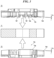
- FIG. 3 is a cross-sectional view of the stator core 11 and the insulators 12, 13 taken along a line III-III in FIG. 2 .
- a peripheral portion 12d projects toward the insulator 13 more than the center portion 12a.
- the center portion 13a projects toward the insulator 12 more than a peripheral portion 13d. That is, the facing portion 12c of the insulator 12 is recessed in a substantially mortar shape, and the facing portion 13c of the insulator 13 projects in a substantially truncated cone shape.
- the facing portion 12c of the insulator 12 is uniformly inclined from the center portion 12a toward the peripheral portion 12d.
- An inclination angle of the facing portion 12c of the insulator 12, that is, an inclination angle ⁇ 1 from the peripheral portion 12d to the center portion 12a is set to 10° or less, and preferably set to 5°.
- the facing portion 13c of the insulator 13 is also uniformly inclined from the center portion 13a to the peripheral portion 13d.
- An inclination angle of the facing portion 13c of the insulator 13, that is, an inclination angle ⁇ 2 from the center portion 13a to the peripheral portion 13d is set to 10° or less, and preferably set to 5°.
- the facing portion 12c faces the stator core 11 when the insulator 12 is mounted to the stator core 11
- the facing portion 13c faces the stator core 11 when the insulator 13 is mounted to the stator core 11.
- each tooth covering portion 13b located in the center portion 13a engages with the corresponding tooth 11b.
- a part of each tooth covering portion 13b slides on the side surface of the tooth 11b and functions as a guide for the tooth 11b.
- work efficiency of mounting the insulator 12 and the insulator 13 to the stator core 11 can be improved.
- the facing portion 12c of the insulator 12 and the facing portion 13c of the insulator 13, which are mounted to the stator core 11, abut against each other.
- FIGS. 5 , 6 and 11 are perspective views showing the configurations of the tooth covering portion 12b of the insulator 12 and the tooth covering portion 13b of the insulator 13.
- FIGS. 7 and 8 are front views showing the configurations of the tooth covering portion 12b of the insulator 12 and the tooth covering portion 13b of the insulator 13.
- Each of FIGS. 5 , 6 , 7 , 8 , and 11 shows only one tooth covering portion 12b and one tooth covering portion 13b.
- the tooth covering portion 12b is a cover having a substantially rectangular tube shape projecting from the center portion 12a, and partially opened so as to be able to accommodate a part of the tooth 11b therein.
- the tooth covering portion 13b is a cover having a substantially rectangular tube shape projecting from the center portion 13a, and partially opened so as to be able to accommodate a part of the tooth 11b therein ( FIGS. 5 , 7 , and 11 ).
- the facing portion 12c of the insulator 12 is recessed in a substantially mortar shape, and is uniformly inclined from the center portion 12a toward the peripheral portion 12d. Therefore, also a facing portion (hereinafter simply referred to as a "lower portion") (first end portion) of the tooth covering portion 12b facing the tooth covering portion 13b is uniformly inclined from the center portion 12a to the peripheral portion 12d without forming a corner therebetween.
- the facing portion 13c of the insulator 13 projects in a substantially truncated cone shape, and is uniformly inclined from the center portion 13a toward the peripheral portion 13d.
- a facing portion (hereinafter simply referred to as an "upper portion") (second end portion) of the tooth covering portion 13b facing the tooth covering portion 12b is uniformly inclined from the center portion 13a to the peripheral portion 13d without forming a corner therebetween, correspondingly to the lower portion of the tooth covering portion 12b.
- each insertion portion 71 into each slot by inclining a front end portion 70a of each insertion portion 71 of each insulator 70 for sandwiching a stator core so as to projects more as proceeding toward the center portion of each insulator 70.
- the inclination angle from the center portion 12a to the peripheral portion 12d of the lower portion of the tooth covering portion 12b, the lower portion being uniformly inclined, and the inclination angle from the center portion 13a to the peripheral portion 13d of the upper portion of the tooth covering portion 13b, the upper portion being uniformly inclined, are set to be identical to each other. Therefore, when the insulators 12, 13 are mounted to the stator core 11, the lower portion of the tooth covering portion 12b and the upper portion of the tooth covering portion 13b abut against each other without a gap therebetween ( FIGS. 6 and 8 ). As a result, the tooth covering portion 12b and the tooth covering portion 13b can completely cover the tooth 11b housed inside, and the insulation property of each tooth 11b of the stator core 11 can be improved.
- the upper portion of the tooth covering portion 13b has a tapered shape that is tapered toward the tooth covering portion 12b.
- a guide 13e formed by wall portions that are inwardly inclined as proceeding toward the tooth covering portion 12b is formed in the upper portion of the tooth covering portion 13b.
- the lower portion of the tooth covering portion 12b has a receptacle shape that widens as proceeding toward the tooth covering portion 13b correspondingly to the tapered shape of the upper portion of the tooth covering portion 13b.
- a guide opening 12e formed by wall portions that are outwardly inclined as proceeding toward the tooth covering portion 13b is formed in the lower portion of the insulator 12.
- the guide 13e of the tooth covering portion 13b is inserted into the guide opening 12e of the tooth covering portion 12b.
- the lower portion of the tooth covering portion 12b and the upper portion of the tooth covering portion 13b can be reliably engaged, and the tooth 11b can be reliably covered. Further, it is possible to prevent the tooth covering portion 12b from being displaced with respect to the tooth covering portion 13b.
- the guide 13e is tapered as proceeding toward the tooth covering portion 12b and the guide opening 12e is widened as proceeding toward the tooth covering portion 13b, the guide 13e can be easily inserted into the guide opening 12e, and thus ease of combining the insulator 12 and the insulator 13 can be improved.
- the guide 13e is configured by the wall portions that are inclined inward, and the guide opening 12e is configured by the wall portions that are inclined outward. Therefore, an integrated thickness of the insulator 12 and the insulator 13 at a fitting portion where the guide 13e is fitted to the guide opening 12e can be reduced. As a result, it is possible to increase a space for winding the coil wire around the tooth 11b and increase the number of turns of the coil 14.
- a center-side guide 13f (see FIGS. 2 and 5 ) that is inclined toward the center of the insulator 13 as proceeding toward the tooth covering portion 12b is formed in an upper portion of the center portion 13a of the tooth covering portion 13b.
- a peripheral-side guide 13g (see FIGS. 2 and 11 ) that is inclined toward the periphery of the insulator 13 as proceeding toward the tooth covering portion 12b is formed in an upper portion of the peripheral portion 13d of the tooth covering portion 13b.
- a center-side receiver 12f (see FIGS. 3 , 4 , and 11 ) that is inclined toward the periphery of the insulator 12 as proceeding toward the tooth covering portion 13b is formed in a lower portion of the center portion 12a of the tooth covering portion 12b.
- a peripheral-side receiver 12g (see FIGS. 2 and 5 ) that is inclined toward the center of the insulator 12 as proceeding toward the tooth covering portion 13b is formed in a lower portion of the peripheral portion 12d of the tooth covering portion 12b.
- the inclination angle of the peripheral-side receiver 12g of the tooth covering portion 12b and the inclination angle of the peripheral-side guide 13g of the tooth covering portion 13b are substantially identical to each other. Therefore, when the lower portion of the tooth covering portion 12b and the upper portion of the tooth covering portion 13b abut against each other, the peripheral-side guide 13g guides the peripheral-side receiver 12g.
- the inclination angle of the center-side receiver 12f of the tooth covering portion 12b and the inclination angle of the center-side guide 13f of the tooth covering portion 13b are substantially identical to each other. Therefore, when the lower portion of the tooth covering portion 12b and the upper portion of the tooth covering portion 13b abut against each other, the center-side guide 13f guides the center-side receiver 12f. That is, the center-side receiver 12f, the peripheral-side receiver 12g, the center-side guide 13f, and the peripheral-side guide 13g can achieve similar effects as those of the guide opening 12e and the guide 13e.
- another center-side guide 13h (see FIG. 11 ) that is inclined toward the periphery of the insulator 13 as proceeding toward the tooth covering portion 12b is formed. Since the other center-side guide 13h is inclined toward the periphery of the insulator 13, the other center-side guide 13h functions as a guide for the center portion 11a of the stator core 11 when the center portion 13a of the insulator 13 engages with the stator core 11. As a result, the insulator 13 can be smoothly mounted to the stator core 11.
- the stator core 11 is formed by stacking a large number of thin metal plates and punching the large number of thin metal plates that are stacked by a press. Therefore, a burr 11d may be formed at one end or the other end of each tooth 11b of the stator core 11 ( FIG. 9A ).
- a burr 11d may be formed at one end or the other end of each tooth 11b of the stator core 11 ( FIG. 9A ).
- the guide 13e of the tooth covering portion 13b is formed by the wall portions that are inclined inward, the guide 13e and the burr 11d interfere with each other. As a result, there is risk that the insulator 13 is not smoothly mounted to the stator core 11 ( FIG. 9B ).
- the insulator 12 is mounted from the side of the stator core 11 where the burr 11d is formed ( FIG. 10A ). Since the guide opening 12e of the tooth covering portion 12b of the insulator 12 widens as proceeding toward the tooth covering portion 13b, the burr 11d is less likely to interfere with the insulator 12 and the insulator 12 can be smoothly mounted to the stator core 11 ( FIG. 10B ). As a result of mounting the insulator 12 to the stator core 11, each tooth covering portion 12b covers the side of each tooth 11b where the burr 11d is formed.
- the center-side receiver 12f of the tooth covering portion 12b is inclined toward the periphery of the insulator 12 as proceeding toward the tooth covering portion 13b.
- the peripheral-side receiver 12g of the tooth covering portion 12b is inclined toward the center of the insulator 12 as proceeding toward the tooth covering portion 13b. Therefore, similarly to the guide opening 12e, the center-side receiver 12f and the peripheral-side receiver 12g are less likely to interfere with the burr 11d, and can contribute to smooth mounting of the insulator 12 to the stator core 11.
- each tooth covering portion 13b of the insulator 13 has a tapered shape; however, the lower portion of each tooth covering portion 12b of the insulator 12 may have a tapered shape.
- the upper portion of each tooth covering portion 13b has a receptacle shape that widens as proceeding toward the tooth covering portion 12b.
- a guide or a guide opening may not be formed in the lower portion of each tooth covering portion 12b or the upper portion of each tooth covering portion 13b.
- the lower portion of the tooth covering portion 12b and the upper portion of the tooth covering portion 13b abut against each other without a gap therebetween.
- a gap so small that a coil wire cannot enter even if the coil wire is warped may be formed between the lower portion of the tooth covering portion 12b and the upper portion of the tooth covering portion 13b. That is, the lower portion of the tooth covering portion 12b and the upper portion of the tooth covering portion 13b do not necessarily have to abut against each other without a gap therebetween.
Landscapes
- Engineering & Computer Science (AREA)
- Power Engineering (AREA)
- Manufacturing & Machinery (AREA)
- Insulation, Fastening Of Motor, Generator Windings (AREA)
- Manufacture Of Motors, Generators (AREA)
Description
- The present invention relates to an insulator set and a stator used for a generator and an electric motor. In particular, the invention relates to an insulator set according to the preamble part of claim 1. Such insulator set is known from
US 2017/126090 A1 . - As one mode of a stator used for a generator and an electric motor, there is known a stator including a stator core having a plurality of teeth arranged radially and two insulators sandwiching the stator core from above and below (for example, see
Japanese Laid-Open Patent Publication (Kokai) No. H07-298529 - However, in recent years, the number of teeth of a stator core has increased in response to an increase in required electromotive force and required output. Therefore, a slot becomes smaller and ease of insertion of each insertion portion into each slot is lowered. In addition, since the number of slots has increased, when each insertion portion is inserted into each slot, rubbing of each insertion portion and each tooth often occurs, and again, ease of insertion of each insertion portion into each slot is lowered. As a result, work efficiency of mounting two insulators to a stator core is lowered.
- The present invention is an insulator set as defined in the independent claim 1. Further embodiments of the invention are defined in the dependent claims 2 - 7.
- Provided is an insulator set including a first insulator and a second insulator that sandwich a stator core therebetween. The stator core includes a plurality of teeth that radially projects from a center portion of the stator core. The first insulator includes a plurality of first tooth covering portions that radially projects from a center portion of the first insulator. The second insulator has a plurality of second tooth covering portions that radially projects from a center portion of the second insulator. The plurality of first tooth covering portions and the plurality of second tooth covering portions cover the plurality of teeth. In a facing portion of the first insulator that faces the second insulator, a peripheral portion of the first insulator projects more than the center portion of the first insulator. In a facing portion of the second insulator that faces the first insulator, the center portion of the second insulator projects more than a peripheral portion of the second insulator.
- The peripheral portion projects more than the center portion in the facing portion of the first insulator facing the second insulator. Therefore, when the first insulator is mounted to the stator core, first, the peripheral portion is inserted into the stator core, and functions as a guide. Furthermore, the center portion projects more than the peripheral portion in the facing portion of the second insulator facing the first insulator. Therefore, when the second insulator is mounted to the stator core, first, the center portion is inserted into the stator core, and functions as a guide. As a result, work efficiency of mounting the first insulator and the second insulator to the stator core can be improved.
- Further features of the present invention will become apparent from the following description of exemplary embodiments (with reference to the attached drawings).
-
-
FIG. 1 is a perspective view schematically showing a configuration of a stator according to an embodiment of the present invention. -
FIG. 2 is an exploded perspective view indicating the configuration of the stator according to the embodiment of the present invention. -
FIG. 3 is a cross-sectional view of the stator core and each insulator taken along a line III-III inFIG. 2 . -
FIG. 4 is a cross-sectional view indicating a mode upon work of mounting each insulator to the stator core. -
FIG. 5 is a perspective view showing a state in which a first tooth covering portion of the first insulator and a second tooth covering portion of the second insulator are separated from each other when viewed from a peripheral side of the first insulator and the second insulator. -
FIG. 6 is a perspective view showing a state in which the first tooth covering portion of the first insulator and the second tooth covering portion of the second insulator abut against each other when viewed from the peripheral side of the first insulator and the second insulator. -
FIG. 7 is a front view showing a state in which the first tooth covering portion of the first insulator and the second tooth covering portion of the second insulator are separated from each other when viewed from the peripheral side of the first insulator and the second insulator. -
FIG. 8 is a front view showing a state in which the first tooth covering portion of the first insulator and the second tooth covering portion of the second insulator abut against each other when viewed from the peripheral side of the first insulator and the second insulator. -
FIGS. 9A and9B are process drawings indicating a problem in mounting the insulators to the stator core when a burr is formed on a tooth. -
FIGS. 10A and10B are process drawings indicating a method for mounting the insulators to the stator core when a burr is formed on the tooth. -
FIG. 11 is a perspective view showing a state in which the first tooth covering portion of the first insulator and the second tooth covering portion of the second insulator are separated from each other when viewed from a center side of the first insulator and the second insulator. -
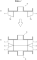
FIG. 12 is a cross-sectional view indicating a mode and a problem of an insulator in which ease of insertion of the stator into each slot is improved. - Hereinafter, an embodiment of the present invention will be described in detail with reference to the drawings.
-
FIG. 1 is a perspective view schematically showing a structure of a stator according to the present embodiment.FIG. 2 is an exploded perspective view indicating the structure of the stator according to the present embodiment. It should be noted that, inFIG. 2 , illustration of acoil 14 described later is omitted. - In
FIGS. 1 and2 , astator 10 includes astator core 11 andinsulators 12, 13 (first insulator, second insulator) that sandwich thestator core 11 therebetween. Thestator core 11 is a laminated body of thin metal plates, and includes a center portion 11a that has a substantially cylindrical shape, andteeth 11b, which are a plurality of yokes that projects from the center portion 11a radially with respect to a center axis of the center portion 11a. - The
insulator 12 mounted from one side to thestator core 11 includes acenter portion 12a and a plurality oftooth covering portions 12b (first tooth covering portions) each having a substantially U-shaped cross section and projecting from thecenter portion 12a correspondingly to eachtooth 11b. Furthermore, theinsulator 13 mounted from the other side to thestator core 11 includes acenter portion 13a and a plurality oftooth covering portions 13b (second tooth covering portions) each having a substantially U-shaped cross section and projecting from thecenter portion 13a correspondingly to eachtooth 11b. Theinsulator 12 and theinsulator 13 form an insulator set. - When the
insulators stator core 11 therebetween, theteeth 11b are covered with thetooth covering portions tooth 11b covered with thetooth covering portions coil 14. Therefore, thetooth covering portions coil 14 and thetooth 11b, and thetooth 11b is insulated from thecoil 14. - The
stator 10 is covered with a rotor (not shown) that is a rotatable cover. A plurality of magnets is arranged inside a side wall surface of the rotor so as to face theteeth 11b, respectively. In a case where thestator 10 is used for an electric motor, a magnetic field is generated by energizing eachcoil 14, and the rotor is rotated around the center axis of the center portion 11a of thestator core 11 due to interaction between the generated magnetic field and the magnetic field of each magnet of the rotor. In a case where thestator 10 is used for a generator, the rotor rotates around the center axis of the center portion 11a of thestator core 11. As a result, an induced current due to the magnetic field of each magnet is generated in eachcoil 14. - Furthermore, an
end portion 11c of eachtooth 11b in a radial direction of thestator core 11 is not covered with thetooth covering portion 12b and thetooth covering portion 13b, but is exposed to each magnet of the rotor. As a result, the magnetic field generated by eachtooth 11b and the magnetic field generated by each magnet are efficiently interacted with each other. -
FIG. 3 is a cross-sectional view of thestator core 11 and theinsulators FIG. 2 . - In
FIG. 3 , in a facingportion 12c of theinsulator 12 facing the insulator 13 (facing portion facing the second insulator), aperipheral portion 12d projects toward theinsulator 13 more than thecenter portion 12a. In a facingportion 13c of theinsulator 13 facing the insulator 12 (facing portion facing the first insulator), thecenter portion 13a projects toward theinsulator 12 more than aperipheral portion 13d. That is, the facingportion 12c of theinsulator 12 is recessed in a substantially mortar shape, and the facingportion 13c of theinsulator 13 projects in a substantially truncated cone shape. - The facing
portion 12c of theinsulator 12 is uniformly inclined from thecenter portion 12a toward theperipheral portion 12d. An inclination angle of the facingportion 12c of theinsulator 12, that is, an inclination angle θ1 from theperipheral portion 12d to thecenter portion 12a is set to 10° or less, and preferably set to 5°. The facingportion 13c of theinsulator 13 is also uniformly inclined from thecenter portion 13a to theperipheral portion 13d. An inclination angle of the facingportion 13c of theinsulator 13, that is, an inclination angle θ2 from thecenter portion 13a to theperipheral portion 13d is set to 10° or less, and preferably set to 5°. - It should be noted that the facing
portion 12c faces thestator core 11 when theinsulator 12 is mounted to thestator core 11, and the facingportion 13c faces thestator core 11 when theinsulator 13 is mounted to thestator core 11. - As indicated by arrows in
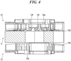
FIG. 3 , when theinsulators stator core 11 so as to sandwich thestator core 11 therebetween, as described above, in the facingportion 12c of theinsulator 12, theperipheral portion 12d projects. Therefore, first, theperipheral portion 12d engages with the stator core 11 (FIG. 4 ). At this time, a part (the lowermost end portion in the figure) of eachtooth covering portion 12b located in theperipheral portion 12d engages with thecorresponding tooth 11b. Further, as theinsulator 12 moves toward theinsulator 13, a part of eachtooth covering portion 12b slides on a side surface of thetooth 11b and functions as a guide for thetooth 11b. Since thecenter portion 13a projects in the facingportion 13c of theinsulator 13, first, thecenter portion 13a engages with the stator core 11 (FIG. 4 ). At this time, a part (the uppermost end portion in the figure) of eachtooth covering portion 13b located in thecenter portion 13a engages with thecorresponding tooth 11b. Further, as theinsulator 13 moves toward theinsulator 12, a part of eachtooth covering portion 13b slides on the side surface of thetooth 11b and functions as a guide for thetooth 11b. As a result, work efficiency of mounting theinsulator 12 and theinsulator 13 to thestator core 11 can be improved. Finally, the facingportion 12c of theinsulator 12 and the facingportion 13c of theinsulator 13, which are mounted to thestator core 11, abut against each other. -
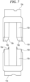
FIGS. 5 ,6 and11 are perspective views showing the configurations of thetooth covering portion 12b of theinsulator 12 and thetooth covering portion 13b of theinsulator 13.FIGS. 7 and8 are front views showing the configurations of thetooth covering portion 12b of theinsulator 12 and thetooth covering portion 13b of theinsulator 13. Each ofFIGS. 5 ,6 ,7 ,8 , and11 shows only onetooth covering portion 12b and onetooth covering portion 13b. - In each of
FIGS. 5 ,6 ,7 ,8 , and11 , thetooth covering portion 12b is a cover having a substantially rectangular tube shape projecting from thecenter portion 12a, and partially opened so as to be able to accommodate a part of thetooth 11b therein. Also, thetooth covering portion 13b is a cover having a substantially rectangular tube shape projecting from thecenter portion 13a, and partially opened so as to be able to accommodate a part of thetooth 11b therein (FIGS. 5 ,7 , and11 ). - As described above, the facing
portion 12c of theinsulator 12 is recessed in a substantially mortar shape, and is uniformly inclined from thecenter portion 12a toward theperipheral portion 12d. Therefore, also a facing portion (hereinafter simply referred to as a "lower portion") (first end portion) of thetooth covering portion 12b facing thetooth covering portion 13b is uniformly inclined from thecenter portion 12a to theperipheral portion 12d without forming a corner therebetween. In addition, the facingportion 13c of theinsulator 13 projects in a substantially truncated cone shape, and is uniformly inclined from thecenter portion 13a toward theperipheral portion 13d. Therefore, also a facing portion (hereinafter simply referred to as an "upper portion") (second end portion) of thetooth covering portion 13b facing thetooth covering portion 12b is uniformly inclined from thecenter portion 13a to theperipheral portion 13d without forming a corner therebetween, correspondingly to the lower portion of thetooth covering portion 12b. - As shown in (a) in
FIG. 12 , it is conceivable to improve ease of insertion of eachinsertion portion 71 into each slot by inclining afront end portion 70a of eachinsertion portion 71 of eachinsulator 70 for sandwiching a stator core so as to projects more as proceeding toward the center portion of eachinsulator 70. - However, in a case where the stator core is sandwiched from above and below by the two
insulators 70 in which thefront end portion 70a of eachinsertion portion 71 that projects more as proceeding toward the center portion, a peripheral portion of eachtooth 72 of the stator core is not covered with eachinsertion portion 71. Therefore, the peripheral portion of eachtooth 72 is exposed ((b) inFIG. 12 ). As a result, there is risk that a coil wire wound around thetooth 72 with theinsertion portion 71 interposed therebetween may contact thetooth 72 around which the coil wire is wound, and thus insulation failure occurs. - In contrast, in the present embodiment, the inclination angle from the
center portion 12a to theperipheral portion 12d of the lower portion of thetooth covering portion 12b, the lower portion being uniformly inclined, and the inclination angle from thecenter portion 13a to theperipheral portion 13d of the upper portion of thetooth covering portion 13b, the upper portion being uniformly inclined, are set to be identical to each other. Therefore, when theinsulators stator core 11, the lower portion of thetooth covering portion 12b and the upper portion of thetooth covering portion 13b abut against each other without a gap therebetween (FIGS. 6 and8 ). As a result, thetooth covering portion 12b and thetooth covering portion 13b can completely cover thetooth 11b housed inside, and the insulation property of eachtooth 11b of thestator core 11 can be improved. - The upper portion of the
tooth covering portion 13b has a tapered shape that is tapered toward thetooth covering portion 12b. Specifically, aguide 13e formed by wall portions that are inwardly inclined as proceeding toward thetooth covering portion 12b is formed in the upper portion of thetooth covering portion 13b. The lower portion of thetooth covering portion 12b has a receptacle shape that widens as proceeding toward thetooth covering portion 13b correspondingly to the tapered shape of the upper portion of thetooth covering portion 13b. Specifically, aguide opening 12e formed by wall portions that are outwardly inclined as proceeding toward thetooth covering portion 13b is formed in the lower portion of theinsulator 12. - When the lower portion of the
tooth covering portion 12b and the upper portion of thetooth covering portion 13b abut against each other, theguide 13e of thetooth covering portion 13b is inserted into the guide opening 12e of thetooth covering portion 12b. As a result, the lower portion of thetooth covering portion 12b and the upper portion of thetooth covering portion 13b can be reliably engaged, and thetooth 11b can be reliably covered. Further, it is possible to prevent thetooth covering portion 12b from being displaced with respect to thetooth covering portion 13b. - Further, since the
guide 13e is tapered as proceeding toward thetooth covering portion 12b and theguide opening 12e is widened as proceeding toward thetooth covering portion 13b, theguide 13e can be easily inserted into theguide opening 12e, and thus ease of combining theinsulator 12 and theinsulator 13 can be improved. - The
guide 13e is configured by the wall portions that are inclined inward, and theguide opening 12e is configured by the wall portions that are inclined outward. Therefore, an integrated thickness of theinsulator 12 and theinsulator 13 at a fitting portion where theguide 13e is fitted to theguide opening 12e can be reduced. As a result, it is possible to increase a space for winding the coil wire around thetooth 11b and increase the number of turns of thecoil 14. - A center-
side guide 13f (seeFIGS. 2 and5 ) that is inclined toward the center of theinsulator 13 as proceeding toward thetooth covering portion 12b is formed in an upper portion of thecenter portion 13a of thetooth covering portion 13b. A peripheral-side guide 13g (seeFIGS. 2 and11 ) that is inclined toward the periphery of theinsulator 13 as proceeding toward thetooth covering portion 12b is formed in an upper portion of theperipheral portion 13d of thetooth covering portion 13b. - A center-
side receiver 12f (seeFIGS. 3 ,4 , and11 ) that is inclined toward the periphery of theinsulator 12 as proceeding toward thetooth covering portion 13b is formed in a lower portion of thecenter portion 12a of thetooth covering portion 12b. A peripheral-side receiver 12g (seeFIGS. 2 and5 ) that is inclined toward the center of theinsulator 12 as proceeding toward thetooth covering portion 13b is formed in a lower portion of theperipheral portion 12d of thetooth covering portion 12b. - The inclination angle of the peripheral-
side receiver 12g of thetooth covering portion 12b and the inclination angle of the peripheral-side guide 13g of thetooth covering portion 13b are substantially identical to each other. Therefore, when the lower portion of thetooth covering portion 12b and the upper portion of thetooth covering portion 13b abut against each other, the peripheral-side guide 13g guides the peripheral-side receiver 12g. The inclination angle of the center-side receiver 12f of thetooth covering portion 12b and the inclination angle of the center-side guide 13f of thetooth covering portion 13b are substantially identical to each other. Therefore, when the lower portion of thetooth covering portion 12b and the upper portion of thetooth covering portion 13b abut against each other, the center-side guide 13f guides the center-side receiver 12f. That is, the center-side receiver 12f, the peripheral-side receiver 12g, the center-side guide 13f, and the peripheral-side guide 13g can achieve similar effects as those of theguide opening 12e and theguide 13e. - Furthermore, in the upper portion of the
center portion 13a of thetooth covering portion 13b, on the side opposite to the center-side guide 13f, that is, on the side facing the center portion 11a of thestator core 11, another center-side guide 13h (seeFIG. 11 ) that is inclined toward the periphery of theinsulator 13 as proceeding toward thetooth covering portion 12b is formed. Since the other center-side guide 13h is inclined toward the periphery of theinsulator 13, the other center-side guide 13h functions as a guide for the center portion 11a of thestator core 11 when thecenter portion 13a of theinsulator 13 engages with thestator core 11. As a result, theinsulator 13 can be smoothly mounted to thestator core 11. - The
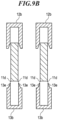
stator core 11 is formed by stacking a large number of thin metal plates and punching the large number of thin metal plates that are stacked by a press. Therefore, aburr 11d may be formed at one end or the other end of eachtooth 11b of the stator core 11 (FIG. 9A ). Here, when theinsulator 13 is mounted from the side where theburr 11d of thestator core 11 is formed (FIG. 9A ), since theguide 13e of thetooth covering portion 13b is formed by the wall portions that are inclined inward, theguide 13e and theburr 11d interfere with each other. As a result, there is risk that theinsulator 13 is not smoothly mounted to the stator core 11 (FIG. 9B ). - In the present embodiment, in order to cope with this, the
insulator 12 is mounted from the side of thestator core 11 where theburr 11d is formed (FIG. 10A ). Since the guide opening 12e of thetooth covering portion 12b of theinsulator 12 widens as proceeding toward thetooth covering portion 13b, theburr 11d is less likely to interfere with theinsulator 12 and theinsulator 12 can be smoothly mounted to the stator core 11 (FIG. 10B ). As a result of mounting theinsulator 12 to thestator core 11, eachtooth covering portion 12b covers the side of eachtooth 11b where theburr 11d is formed. - Further, as described above, the center-
side receiver 12f of thetooth covering portion 12b is inclined toward the periphery of theinsulator 12 as proceeding toward thetooth covering portion 13b. The peripheral-side receiver 12g of thetooth covering portion 12b is inclined toward the center of theinsulator 12 as proceeding toward thetooth covering portion 13b. Therefore, similarly to theguide opening 12e, the center-side receiver 12f and the peripheral-side receiver 12g are less likely to interfere with theburr 11d, and can contribute to smooth mounting of theinsulator 12 to thestator core 11. - Although a preferred embodiment of the present invention has been described above, the present invention is not limited to the above-described embodiment, and various modifications and changes can be made within the scope of the claims.
- For example, in the present embodiment, the upper portion of each
tooth covering portion 13b of theinsulator 13 has a tapered shape; however, the lower portion of eachtooth covering portion 12b of theinsulator 12 may have a tapered shape. In this case, the upper portion of eachtooth covering portion 13b has a receptacle shape that widens as proceeding toward thetooth covering portion 12b. Furthermore, a guide or a guide opening may not be formed in the lower portion of eachtooth covering portion 12b or the upper portion of eachtooth covering portion 13b. - Moreover, in the present embodiment, the lower portion of the
tooth covering portion 12b and the upper portion of thetooth covering portion 13b abut against each other without a gap therebetween. However, a gap so small that a coil wire cannot enter even if the coil wire is warped may be formed between the lower portion of thetooth covering portion 12b and the upper portion of thetooth covering portion 13b. That is, the lower portion of thetooth covering portion 12b and the upper portion of thetooth covering portion 13b do not necessarily have to abut against each other without a gap therebetween. - This application claims the benefit of
Japanese Patent Application No. 2019-196225 filed on October 29, 2019
Claims (7)
- An insulator set including a first insulator (12) and a second insulator (13) for sandwiching a stator core therebetween, whereinthe stator core includes a plurality of teeth that radially projects from a center portion of the stator core,the first insulator includes a plurality of first tooth covering portions (12b) that radially projects from a center portion (12a) of the first insulator,the second insulator includes a plurality of second tooth covering portions (13b) that radially projects from a center portion (13a) of the second insulatorthe plurality of first tooth covering portions and the plurality of second tooth covering portions cover the plurality of teeth,in a facing portion (12c) of the first insulator that faces the second insulator, a peripheral portion (12d) of the first insulator axially projects more towards the second insulator than the center portion of the first insulator, andin a facing portion (13c) of the second insulator that faces the first insulator, the center portion of the second insulator axially projects more towards the first insulator than a peripheral portion (13d) of the second insulator, andwhen the first insulator and the second insulator sandwich the stator core therebetween, the facing portion that faces the second insulator abuts against the facing portion that faces the first insulator,characterised in that the facing portion (12c) of the first insulator that faces the second insulator is uniformly inclined from the center portion (12a) of the first insulator to the peripheral portion (12d) of the first insulator, and the facing portion (13c) of the second insulator that faces the first insulator is uniformly inclined from the center portion (13a) of the second insulator to the peripheral portion (13d) of the second insulator.
- The insulator set according to claim 1, wherein a first end portion serving as a facing portion of each of the plurality of first tooth covering portions (12b) that faces each of the plurality of second tooth covering portions (13b) is inclined, and a second end portion serving as a facing portion of each of the plurality of second tooth covering portions that faces each of the plurality of first tooth covering portions is inclined correspondingly to the first end portion.
- The insulator set according to claim 2, wherein the second end portion has a tapered shape (13e), and the first end portion has a receptacle shape (12e) corresponding to the tapered shape.
- The insulator set according to claim 2, wherein an inclination angle of the first end portion and an inclination angle of the second end portion are set to be identical to each other, the first end portion and the second end portion abut against each other without a gap therebetween, and thereby the plurality of first tooth covering portions and the plurality of second tooth covering portions cover the entirety of the plurality of teeth.
- The insulator set according to claim 2, whereinthe second end portion of each of the plurality of second tooth covering portions in the center portion of the second insulator includes a center-side guide (13f) that is inclined toward a center of the second insulator as proceeding toward each of the plurality of first tooth covering portions,the second end portion of each of the plurality of second tooth covering portions in the peripheral portion of the second insulator includes a peripheral-side guide (13g) that is inclined toward a periphery of the second insulator as proceeding toward each of the plurality of first tooth covering portions,the first end portion of each of the plurality of first tooth covering portions in the center portion (12a) of the first insulator includes a center-side receiver (12f) that is inclined toward a periphery of the first insulator as proceeding toward each of the plurality of second tooth covering portions, andthe first end portion of each of the plurality of first tooth covering portions in the peripheral portion (12d) of the first insulator includes a peripheral-side receiver that is inclined toward a center of the first insulator as proceeding toward each of the plurality of second tooth covering portions.
- The insulator set according to claim 5, wherein another center-side guide (13h)
that is inclined toward the periphery of the second insulator as proceeding toward each of the plurality of first tooth covering portions is formed in the second end portion of each of the plurality of second tooth covering portions in the center portion of the second insulator, on a side opposite to the center-side guide. - The insulator set according to claim 1, wherein each of the plurality of first tooth covering portions of the first insulator covers a side of each of the plurality of teeth of the stator core on which a burr (11d) is formed.
Applications Claiming Priority (1)
| Application Number | Priority Date | Filing Date | Title |
|---|---|---|---|
| JP2019196225A JP7385430B2 (en) | 2019-10-29 | 2019-10-29 | Insulator assembly, stator and stator manufacturing method |
Publications (2)
| Publication Number | Publication Date |
|---|---|
| EP3817199A1 EP3817199A1 (en) | 2021-05-05 |
| EP3817199B1 true EP3817199B1 (en) | 2024-09-11 |
Family
ID=72644097
Family Applications (1)
| Application Number | Title | Priority Date | Filing Date |
|---|---|---|---|
| EP20197951.5A Active EP3817199B1 (en) | 2019-10-29 | 2020-09-24 | Insulator set and stator used for generator and electric motor |
Country Status (3)
| Country | Link |
|---|---|
| US (1) | US11632010B2 (en) |
| EP (1) | EP3817199B1 (en) |
| JP (1) | JP7385430B2 (en) |
Families Citing this family (2)
| Publication number | Priority date | Publication date | Assignee | Title |
|---|---|---|---|---|
| DE102022123790A1 (en) * | 2022-09-16 | 2024-03-21 | Valeo Eautomotive Germany Gmbh | Improved rotor insulation for a rotor base body of a rotor of an electrical machine |
| JP2024119643A (en) * | 2023-02-22 | 2024-09-03 | パナソニックIpマネジメント株式会社 | Stator, motor |
Family Cites Families (11)
| Publication number | Priority date | Publication date | Assignee | Title |
|---|---|---|---|---|
| JPH04312336A (en) * | 1991-04-09 | 1992-11-04 | Mitsubishi Electric Corp | Stator for motor |
| JP3288531B2 (en) | 1994-04-25 | 2002-06-04 | 山洋電気株式会社 | Stator for rotating electric machine |
| JP2004135365A (en) * | 2002-10-08 | 2004-04-30 | Koito Mfg Co Ltd | Motor |
| JP5122909B2 (en) * | 2007-10-19 | 2013-01-16 | 本田技研工業株式会社 | Rotating electric machine |
| ITMI20110025A1 (en) | 2011-01-14 | 2012-07-15 | Stel S R L | ELECTRIC MOTOR WITH CONTINUOUS CURRENT WITHOUT BRUSHES. |
| JP2013106454A (en) * | 2011-11-15 | 2013-05-30 | Fuji Electric Co Ltd | Stator core of rotary electric machine |
| JP5773164B2 (en) * | 2012-01-31 | 2015-09-02 | 日本電産株式会社 | Armature and motor |
| US8946954B2 (en) * | 2012-04-20 | 2015-02-03 | Nidec Motor Corporation | Integrated direct drive motor and control |
| CN106655554B (en) * | 2015-10-30 | 2021-06-01 | 尼得科电机有限公司 | End caps for outer rotor motors |
| JP7039264B2 (en) * | 2017-11-21 | 2022-03-22 | 山洋電気株式会社 | Rotating machine stator and its assembly method |
| JP7171346B2 (en) | 2018-09-27 | 2022-11-15 | 朋和産業株式会社 | food packaging |
-
2019
- 2019-10-29 JP JP2019196225A patent/JP7385430B2/en active Active
-
2020
- 2020-09-17 US US17/023,439 patent/US11632010B2/en active Active
- 2020-09-24 EP EP20197951.5A patent/EP3817199B1/en active Active
Also Published As
| Publication number | Publication date |
|---|---|
| JP7385430B2 (en) | 2023-11-22 |
| EP3817199A1 (en) | 2021-05-05 |
| US20210126504A1 (en) | 2021-04-29 |
| JP2021072660A (en) | 2021-05-06 |
| US11632010B2 (en) | 2023-04-18 |
Similar Documents
| Publication | Publication Date | Title |
|---|---|---|
| US10566854B2 (en) | Rotating electric machine | |
| EP2320539B1 (en) | Rotary machine stator | |
| US20180006512A1 (en) | Armature and rotating electric machine | |
| EP3193428B1 (en) | Stator | |
| EP3687043B1 (en) | Insulator, and stator and motor comprising same | |
| KR101858914B1 (en) | Insulators for rotary electric motors and rotary electric motors | |
| EP1855369A2 (en) | Stator core of an electric motor | |
| EP3754814B1 (en) | Stator core and compressor | |
| CN110277856B (en) | Stator of a rotating electrical machine | |
| US10693329B2 (en) | Polyphase claw pole motor and stator of the polyphase claw pole motor | |
| EP3817199A1 (en) | Insulator set and stator used for generator and electric motor, and method for manufacturing stator | |
| CN112236925B (en) | Stator of rotating electrical machine and rotating electrical machine | |
| JP7289102B2 (en) | Insulators and stators and motors equipped with them | |
| US20240171031A1 (en) | Motor | |
| KR102262758B1 (en) | Motor | |
| JP4619098B2 (en) | Insulating member for stator and rotating machine having the same | |
| CN115995906A (en) | Motor | |
| JP5256835B2 (en) | Rotating electric machine stator and rotating electric machine | |
| JP2007244069A (en) | Stator core manufacturing method and stator core | |
| KR20230049319A (en) | Motor | |
| CN112821589A (en) | Stator and motor | |
| JP6436825B2 (en) | Stator and stator manufacturing method | |
| JP7229402B2 (en) | Armature manufacturing method and armature | |
| KR101436452B1 (en) | Stator for motor | |
| CN217882982U (en) | Stator and motor |
Legal Events
| Date | Code | Title | Description |
|---|---|---|---|
| PUAI | Public reference made under article 153(3) epc to a published international application that has entered the european phase |
Free format text: ORIGINAL CODE: 0009012 |
|
| STAA | Information on the status of an ep patent application or granted ep patent |
Free format text: STATUS: THE APPLICATION HAS BEEN PUBLISHED |
|
| AK | Designated contracting states |
Kind code of ref document: A1 Designated state(s): AL AT BE BG CH CY CZ DE DK EE ES FI FR GB GR HR HU IE IS IT LI LT LU LV MC MK MT NL NO PL PT RO RS SE SI SK SM TR |
|
| STAA | Information on the status of an ep patent application or granted ep patent |
Free format text: STATUS: REQUEST FOR EXAMINATION WAS MADE |
|
| 17P | Request for examination filed |
Effective date: 20211029 |
|
| RBV | Designated contracting states (corrected) |
Designated state(s): AL AT BE BG CH CY CZ DE DK EE ES FI FR GB GR HR HU IE IS IT LI LT LU LV MC MK MT NL NO PL PT RO RS SE SI SK SM TR |
|
| STAA | Information on the status of an ep patent application or granted ep patent |
Free format text: STATUS: EXAMINATION IS IN PROGRESS |
|
| 17Q | First examination report despatched |
Effective date: 20221130 |
|
| GRAP | Despatch of communication of intention to grant a patent |
Free format text: ORIGINAL CODE: EPIDOSNIGR1 |
|
| STAA | Information on the status of an ep patent application or granted ep patent |
Free format text: STATUS: GRANT OF PATENT IS INTENDED |
|
| INTG | Intention to grant announced |
Effective date: 20240502 |
|
| GRAS | Grant fee paid |
Free format text: ORIGINAL CODE: EPIDOSNIGR3 |
|
| GRAA | (expected) grant |
Free format text: ORIGINAL CODE: 0009210 |
|
| STAA | Information on the status of an ep patent application or granted ep patent |
Free format text: STATUS: THE PATENT HAS BEEN GRANTED |
|
| AK | Designated contracting states |
Kind code of ref document: B1 Designated state(s): AL AT BE BG CH CY CZ DE DK EE ES FI FR GB GR HR HU IE IS IT LI LT LU LV MC MK MT NL NO PL PT RO RS SE SI SK SM TR |
|
| REG | Reference to a national code |
Ref country code: GB Ref legal event code: FG4D |
|
| REG | Reference to a national code |
Ref country code: CH Ref legal event code: EP |
|
| REG | Reference to a national code |
Ref country code: DE Ref legal event code: R096 Ref document number: 602020037435 Country of ref document: DE |
|
| REG | Reference to a national code |
Ref country code: IE Ref legal event code: FG4D |
|
| REG | Reference to a national code |
Ref country code: LT Ref legal event code: MG9D |
|
| PG25 | Lapsed in a contracting state [announced via postgrant information from national office to epo] |
Ref country code: NO Free format text: LAPSE BECAUSE OF FAILURE TO SUBMIT A TRANSLATION OF THE DESCRIPTION OR TO PAY THE FEE WITHIN THE PRESCRIBED TIME-LIMIT Effective date: 20241211 |
|
| REG | Reference to a national code |
Ref country code: NL Ref legal event code: MP Effective date: 20240911 |
|
| PG25 | Lapsed in a contracting state [announced via postgrant information from national office to epo] |
Ref country code: GR Free format text: LAPSE BECAUSE OF FAILURE TO SUBMIT A TRANSLATION OF THE DESCRIPTION OR TO PAY THE FEE WITHIN THE PRESCRIBED TIME-LIMIT Effective date: 20241212 Ref country code: FI Free format text: LAPSE BECAUSE OF FAILURE TO SUBMIT A TRANSLATION OF THE DESCRIPTION OR TO PAY THE FEE WITHIN THE PRESCRIBED TIME-LIMIT Effective date: 20240911 |
|
| PG25 | Lapsed in a contracting state [announced via postgrant information from national office to epo] |
Ref country code: BG Free format text: LAPSE BECAUSE OF FAILURE TO SUBMIT A TRANSLATION OF THE DESCRIPTION OR TO PAY THE FEE WITHIN THE PRESCRIBED TIME-LIMIT Effective date: 20240911 |
|
| PG25 | Lapsed in a contracting state [announced via postgrant information from national office to epo] |
Ref country code: LV Free format text: LAPSE BECAUSE OF FAILURE TO SUBMIT A TRANSLATION OF THE DESCRIPTION OR TO PAY THE FEE WITHIN THE PRESCRIBED TIME-LIMIT Effective date: 20240911 |
|
| PG25 | Lapsed in a contracting state [announced via postgrant information from national office to epo] |
Ref country code: HR Free format text: LAPSE BECAUSE OF FAILURE TO SUBMIT A TRANSLATION OF THE DESCRIPTION OR TO PAY THE FEE WITHIN THE PRESCRIBED TIME-LIMIT Effective date: 20240911 |
|
| PG25 | Lapsed in a contracting state [announced via postgrant information from national office to epo] |
Ref country code: RS Free format text: LAPSE BECAUSE OF FAILURE TO SUBMIT A TRANSLATION OF THE DESCRIPTION OR TO PAY THE FEE WITHIN THE PRESCRIBED TIME-LIMIT Effective date: 20241211 Ref country code: ES Free format text: LAPSE BECAUSE OF FAILURE TO SUBMIT A TRANSLATION OF THE DESCRIPTION OR TO PAY THE FEE WITHIN THE PRESCRIBED TIME-LIMIT Effective date: 20240911 |
|
| PG25 | Lapsed in a contracting state [announced via postgrant information from national office to epo] |
Ref country code: RS Free format text: LAPSE BECAUSE OF FAILURE TO SUBMIT A TRANSLATION OF THE DESCRIPTION OR TO PAY THE FEE WITHIN THE PRESCRIBED TIME-LIMIT Effective date: 20241211 Ref country code: NO Free format text: LAPSE BECAUSE OF FAILURE TO SUBMIT A TRANSLATION OF THE DESCRIPTION OR TO PAY THE FEE WITHIN THE PRESCRIBED TIME-LIMIT Effective date: 20241211 Ref country code: LV Free format text: LAPSE BECAUSE OF FAILURE TO SUBMIT A TRANSLATION OF THE DESCRIPTION OR TO PAY THE FEE WITHIN THE PRESCRIBED TIME-LIMIT Effective date: 20240911 Ref country code: HR Free format text: LAPSE BECAUSE OF FAILURE TO SUBMIT A TRANSLATION OF THE DESCRIPTION OR TO PAY THE FEE WITHIN THE PRESCRIBED TIME-LIMIT Effective date: 20240911 Ref country code: GR Free format text: LAPSE BECAUSE OF FAILURE TO SUBMIT A TRANSLATION OF THE DESCRIPTION OR TO PAY THE FEE WITHIN THE PRESCRIBED TIME-LIMIT Effective date: 20241212 Ref country code: FI Free format text: LAPSE BECAUSE OF FAILURE TO SUBMIT A TRANSLATION OF THE DESCRIPTION OR TO PAY THE FEE WITHIN THE PRESCRIBED TIME-LIMIT Effective date: 20240911 Ref country code: ES Free format text: LAPSE BECAUSE OF FAILURE TO SUBMIT A TRANSLATION OF THE DESCRIPTION OR TO PAY THE FEE WITHIN THE PRESCRIBED TIME-LIMIT Effective date: 20240911 Ref country code: BG Free format text: LAPSE BECAUSE OF FAILURE TO SUBMIT A TRANSLATION OF THE DESCRIPTION OR TO PAY THE FEE WITHIN THE PRESCRIBED TIME-LIMIT Effective date: 20240911 |
|
| REG | Reference to a national code |
Ref country code: AT Ref legal event code: MK05 Ref document number: 1723568 Country of ref document: AT Kind code of ref document: T Effective date: 20240911 |
|
| PG25 | Lapsed in a contracting state [announced via postgrant information from national office to epo] |
Ref country code: NL Free format text: LAPSE BECAUSE OF FAILURE TO SUBMIT A TRANSLATION OF THE DESCRIPTION OR TO PAY THE FEE WITHIN THE PRESCRIBED TIME-LIMIT Effective date: 20240911 |
|
| PG25 | Lapsed in a contracting state [announced via postgrant information from national office to epo] |
Ref country code: IS Free format text: LAPSE BECAUSE OF FAILURE TO SUBMIT A TRANSLATION OF THE DESCRIPTION OR TO PAY THE FEE WITHIN THE PRESCRIBED TIME-LIMIT Effective date: 20250111 Ref country code: PT Free format text: LAPSE BECAUSE OF FAILURE TO SUBMIT A TRANSLATION OF THE DESCRIPTION OR TO PAY THE FEE WITHIN THE PRESCRIBED TIME-LIMIT Effective date: 20250113 |
|
| PG25 | Lapsed in a contracting state [announced via postgrant information from national office to epo] |
Ref country code: SM Free format text: LAPSE BECAUSE OF FAILURE TO SUBMIT A TRANSLATION OF THE DESCRIPTION OR TO PAY THE FEE WITHIN THE PRESCRIBED TIME-LIMIT Effective date: 20240911 Ref country code: RO Free format text: LAPSE BECAUSE OF FAILURE TO SUBMIT A TRANSLATION OF THE DESCRIPTION OR TO PAY THE FEE WITHIN THE PRESCRIBED TIME-LIMIT Effective date: 20240911 |
|
| PG25 | Lapsed in a contracting state [announced via postgrant information from national office to epo] |
Ref country code: EE Free format text: LAPSE BECAUSE OF FAILURE TO SUBMIT A TRANSLATION OF THE DESCRIPTION OR TO PAY THE FEE WITHIN THE PRESCRIBED TIME-LIMIT Effective date: 20240911 Ref country code: AT Free format text: LAPSE BECAUSE OF FAILURE TO SUBMIT A TRANSLATION OF THE DESCRIPTION OR TO PAY THE FEE WITHIN THE PRESCRIBED TIME-LIMIT Effective date: 20240911 |
|
| PG25 | Lapsed in a contracting state [announced via postgrant information from national office to epo] |
Ref country code: CZ Free format text: LAPSE BECAUSE OF FAILURE TO SUBMIT A TRANSLATION OF THE DESCRIPTION OR TO PAY THE FEE WITHIN THE PRESCRIBED TIME-LIMIT Effective date: 20240911 Ref country code: PL Free format text: LAPSE BECAUSE OF FAILURE TO SUBMIT A TRANSLATION OF THE DESCRIPTION OR TO PAY THE FEE WITHIN THE PRESCRIBED TIME-LIMIT Effective date: 20240911 |
|
| PG25 | Lapsed in a contracting state [announced via postgrant information from national office to epo] |
Ref country code: SK Free format text: LAPSE BECAUSE OF FAILURE TO SUBMIT A TRANSLATION OF THE DESCRIPTION OR TO PAY THE FEE WITHIN THE PRESCRIBED TIME-LIMIT Effective date: 20240911 Ref country code: IT Free format text: LAPSE BECAUSE OF FAILURE TO SUBMIT A TRANSLATION OF THE DESCRIPTION OR TO PAY THE FEE WITHIN THE PRESCRIBED TIME-LIMIT Effective date: 20240911 |
|
| REG | Reference to a national code |
Ref country code: CH Ref legal event code: PL |
|
| PG25 | Lapsed in a contracting state [announced via postgrant information from national office to epo] |
Ref country code: LU Free format text: LAPSE BECAUSE OF NON-PAYMENT OF DUE FEES Effective date: 20240924 |
|
| REG | Reference to a national code |
Ref country code: DE Ref legal event code: R097 Ref document number: 602020037435 Country of ref document: DE |
|
| PG25 | Lapsed in a contracting state [announced via postgrant information from national office to epo] |
Ref country code: MC Free format text: LAPSE BECAUSE OF FAILURE TO SUBMIT A TRANSLATION OF THE DESCRIPTION OR TO PAY THE FEE WITHIN THE PRESCRIBED TIME-LIMIT Effective date: 20240911 |
|
| PG25 | Lapsed in a contracting state [announced via postgrant information from national office to epo] |
Ref country code: DK Free format text: LAPSE BECAUSE OF FAILURE TO SUBMIT A TRANSLATION OF THE DESCRIPTION OR TO PAY THE FEE WITHIN THE PRESCRIBED TIME-LIMIT Effective date: 20240911 |
|
| REG | Reference to a national code |
Ref country code: BE Ref legal event code: MM Effective date: 20240930 |
|
| PG25 | Lapsed in a contracting state [announced via postgrant information from national office to epo] |
Ref country code: BE Free format text: LAPSE BECAUSE OF NON-PAYMENT OF DUE FEES Effective date: 20240930 |
|
| PLBE | No opposition filed within time limit |
Free format text: ORIGINAL CODE: 0009261 |
|
| STAA | Information on the status of an ep patent application or granted ep patent |
Free format text: STATUS: NO OPPOSITION FILED WITHIN TIME LIMIT |
|
| PG25 | Lapsed in a contracting state [announced via postgrant information from national office to epo] |
Ref country code: CH Free format text: LAPSE BECAUSE OF NON-PAYMENT OF DUE FEES Effective date: 20240930 |
|
| PG25 | Lapsed in a contracting state [announced via postgrant information from national office to epo] |
Ref country code: IE Free format text: LAPSE BECAUSE OF NON-PAYMENT OF DUE FEES Effective date: 20240924 |
|
| 26N | No opposition filed |
Effective date: 20250612 |
|
| GBPC | Gb: european patent ceased through non-payment of renewal fee |
Effective date: 20241211 |
|
| PG25 | Lapsed in a contracting state [announced via postgrant information from national office to epo] |
Ref country code: SE Free format text: LAPSE BECAUSE OF FAILURE TO SUBMIT A TRANSLATION OF THE DESCRIPTION OR TO PAY THE FEE WITHIN THE PRESCRIBED TIME-LIMIT Effective date: 20240911 |
|
| PGFP | Annual fee paid to national office [announced via postgrant information from national office to epo] |
Ref country code: DE Payment date: 20250926 Year of fee payment: 6 |
|
| PG25 | Lapsed in a contracting state [announced via postgrant information from national office to epo] |
Ref country code: GB Free format text: LAPSE BECAUSE OF NON-PAYMENT OF DUE FEES Effective date: 20241211 |
|
| PG25 | Lapsed in a contracting state [announced via postgrant information from national office to epo] |
Ref country code: FR Free format text: LAPSE BECAUSE OF NON-PAYMENT OF DUE FEES Effective date: 20241111 |
|
| PG25 | Lapsed in a contracting state [announced via postgrant information from national office to epo] |
Ref country code: CY Free format text: LAPSE BECAUSE OF FAILURE TO SUBMIT A TRANSLATION OF THE DESCRIPTION OR TO PAY THE FEE WITHIN THE PRESCRIBED TIME-LIMIT; INVALID AB INITIO Effective date: 20200924 |
|
| PG25 | Lapsed in a contracting state [announced via postgrant information from national office to epo] |
Ref country code: HU Free format text: LAPSE BECAUSE OF FAILURE TO SUBMIT A TRANSLATION OF THE DESCRIPTION OR TO PAY THE FEE WITHIN THE PRESCRIBED TIME-LIMIT; INVALID AB INITIO Effective date: 20200924 |