JP5122909B2 - Rotating electric machine - Google Patents
Rotating electric machine Download PDFInfo
- Publication number
- JP5122909B2 JP5122909B2 JP2007272640A JP2007272640A JP5122909B2 JP 5122909 B2 JP5122909 B2 JP 5122909B2 JP 2007272640 A JP2007272640 A JP 2007272640A JP 2007272640 A JP2007272640 A JP 2007272640A JP 5122909 B2 JP5122909 B2 JP 5122909B2
- Authority
- JP
- Japan
- Prior art keywords
- insulator
- rotor
- mating surface
- divided
- piece
- Prior art date
- Legal status (The legal status is an assumption and is not a legal conclusion. Google has not performed a legal analysis and makes no representation as to the accuracy of the status listed.)
- Expired - Fee Related
Links
Images


Classifications
-
- H—ELECTRICITY
- H02—GENERATION; CONVERSION OR DISTRIBUTION OF ELECTRIC POWER
- H02K—DYNAMO-ELECTRIC MACHINES
- H02K3/00—Details of windings
- H02K3/32—Windings characterised by the shape, form or construction of the insulation
- H02K3/34—Windings characterised by the shape, form or construction of the insulation between conductors or between conductor and core, e.g. slot insulation
- H02K3/345—Windings characterised by the shape, form or construction of the insulation between conductors or between conductor and core, e.g. slot insulation between conductor and core, e.g. slot insulation
Description
この発明は発電機や電動機などの回転電機に関し、より具体的にはそのスロットに介挿されるインシュレータの構造に関する。 The present invention relates to a rotating electrical machine such as a generator or an electric motor, and more specifically to a structure of an insulator inserted in a slot.
発電機や電動機などの回転電機の複数個のティースに装着されるインシュレータの構造としては、例えば下記の特許文献1記載の技術が知られている。特許文献1記載の技術にあっては、インシュレータはティースごとに用意されると共に、ロータの回転軸線に平行な縦方向に左右2片に分割されて巻線の巻回を容易にしている。
この種の分割型のインシュレータは、組立性を考慮すると、分割された端部の合わせ面形状が同一であることが望ましく、沿面距離(2つの導電性部分間の絶縁物の表面に沿った最短距離)も長い方が望ましい。その点、特許文献1記載の技術にあっては、インシュレータが縦方向に分割されているため、沿面距離は十分であるものの、合わせ面の形状が異なるため、作業性において不満が残るものであった。
In consideration of assemblability, this type of divided insulator desirably has the same shape of the mating surface of the divided ends, and the creepage distance (the shortest distance along the surface of the insulator between the two conductive portions). Longer distances are desirable. On the other hand, in the technique described in
従って、この発明の目的は上記した課題を解消することにあり、作業性を向上させると共に、沿面距離も長くした分割型のインシュレータを備える回転電機を提供することにある。 Accordingly, an object of the present invention is to eliminate the above-described problems, and to provide a rotating electrical machine including a split type insulator with improved workability and a long creepage distance.
上記の目的を達成するために、請求項1にあっては、ロータと、ステータと、前記ロータとステータのいずれかに形成される複数個のティースと、前記複数個のティースの間のスロットに挿入されて前記複数個のティースに装着されると共に、その上に巻線が巻回されるインシュレータとを少なくとも備える回転電機において、前記インシュレータが前記スロットの2n個(n≧1)分ごとに前記ロータの回転軸線と平行な縦方向に分割される一方、前記ロータの回転軸線に直交する横方向に分割されるインシュレータ片からなると共に、前記横方向に分割された上下のインシュレータ片の合わせ面が同一形状で、かつ沿面距離が前記横方向の距離を超えるように構成され、前記合わせ面が前記上下のインシュレータ片のクランク部位またはテーパ部位を相互に対向させるクランク形状またはテーパ形状に構成されると共に、前記合わせ面における前記インシュレータ片の外周側の前記クランク部位または前記テーパ部位が内周側に向けて縮径するように構成した。
In order to achieve the above object, in
請求項2に係る回転電機にあっては、前記インシュレータは、その肉厚が前記合わせ面に向けて徐々に増加させられる如く構成した。 In the rotary electric machine according to claim 2 , the insulator is configured such that the thickness thereof is gradually increased toward the mating surface.
請求項1に係る回転電機にあっては、インシュレータがスロットの2n個(n≧1)分ごとにロータの回転軸線と平行な縦方向に分割される一方、それに直交する横方向に分割されるインシュレータ片からなると共に、横方向に分割された上下のインシュレータ片の合わせ面が同一形状で、かつ沿面距離が横方向の距離を超えるように構成され、合わせ面が上下のインシュレータ片のクランク部位またはテーパ部位を相互に対向させるクランク形状またはテーパ形状に構成されると共に、合わせ面におけるインシュレータ片の外周側のクランク部位またはテーパ部位が内周側に向けて縮径するように構成したので、インシュレータ片の横方向に分割された端部の合わせ面が同一形状にされたことで組立作業時の取り付け違いを防止できて作業性を向上させることができる。また、沿面距離が横方向の距離を超える形状、即ち、クランク形状またはテーパ形状としたことで、横方向の距離を超える分だけ沿面距離を長くすることができる。
In the rotating electrical machine according to
請求項2に係る回転電機にあっては、インシュレータはその肉厚が合わせ面に向けて徐々に増加させられる如く構成したので、上記した効果に加え、合わせ面の沿面距離を一層長くできると共に、肉厚を徐々に増加させる、換言すれば大幅に増加させないことで、合わせ面の付近に適度な隙間を確保することができて巻線の巻回作業をスムーズに行うことができる。 In the rotating electrical machine according to claim 2 , since the insulator is configured such that its thickness is gradually increased toward the mating surface, in addition to the above effect, the creepage distance of the mating surface can be further increased, By gradually increasing the wall thickness, in other words, not significantly increasing the thickness, an appropriate gap can be secured in the vicinity of the mating surfaces, and the winding work can be performed smoothly.
以下、添付図面に即してこの発明に係る回転電機を実施するための最良の形態について説明する。 The best mode for carrying out the rotating electrical machine according to the present invention will be described below with reference to the accompanying drawings.
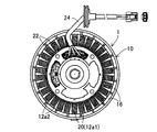
図1は、この発明の第1実施例に係る回転電機を全体的に示す平面図、図2はその側面図、図3はステータの拡大平面図、図4は図3に示すステータのステータコアなどの説明斜視図である。 1 is a plan view generally showing a rotating electrical machine according to a first embodiment of the present invention, FIG. 2 is a side view thereof, FIG. 3 is an enlarged plan view of a stator, FIG. 4 is a stator core of the stator shown in FIG. FIG.
図1から図3に示す如く、第1実施例に係る回転電機(符号1で示す)は、アウタ側に配設されたロータ10と、それに対向してインナ側に配設されたステータ12を備える。ロータ10は内燃機関(エンジン)のクランク軸14に取り付けられる。ロータ10の内周には20個の永久磁石16が極性を交互に相違させながら配置される。
As shown in FIGS. 1 to 3, the rotating electrical machine (indicated by reference numeral 1) according to the first embodiment includes a
図4に示す如く、ステータ12はステータコア12aを備え、ステータコア12aには複数個、即ち、30個のティース12a1が形成されると共に、そのティース12a1の間に同数個のスロット12a2が穿設される。ステータコア12aは鋼板を積層されてなる。ティース12a1はそれぞれT字状を呈し、径方向に延びる基部12a11と、基部12a11に一体に形成される、円周側の頭部12a12とからなる。
As shown in FIG. 4, the
ステータコア12aのティース12a1の基部12a11には、インシュレータ(ボビン)20が装着される。インシュレータ20はスロット12a2から挿入されてティース12a1に装着され、その上には細い電線(エナメル線)からなる巻線(コイル)22が巻回される。
An insulator (bobbin) 20 is attached to the base 12a11 of the teeth 12a1 of the
第1実施例に係る回転電機1は、図示の如く、アウタロータ型のエンジン発電機として構成され、エンジンのクランク軸14の回転に伴ってロータ10が回転してロータ10に配置された永久磁石16の磁束をステータ12に巻回された巻線22が横切ると、巻線22には起電力(交流電力)が生じる。よって生じた起電力は3本の出力線24を介して3相交流電力として取り出される。
As shown in the drawing, the rotating
第1実施例に係る回転電機1の特徴はインシュレータ20の構造にあるので、以下それについて詳細に説明する。
Since the feature of the rotating
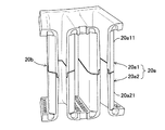
図5は図4に示す上部インシュレータ片20a1の拡大斜視図、図6は図4に示す上部インシュレータ片20a1と下部インシュレータ片20a2を組み合わせてなる1組のインシュレータ片20aの拡大斜視図、図7は図6などに示す左右2組のインシュレータ片20aが横方向に接続されたときの正面図、図8は図7に示す接続部位のインシュレータ片20aの拡大正面図、図9は図7に示すインシュレータ片20aの合わせ面付近の拡大正面図である。
FIG. 5 is an enlarged perspective view of the upper insulator piece 20a1 shown in FIG. 4, FIG. 6 is an enlarged perspective view of a pair of
図示の如く、インシュレータ20はスロット12a2の2n個(n≧1)分、実施例の場合はn=1、即ち、2個のスロット12a2に対応する部位ごとにロータ10の回転軸線10a(図4に示す)と平行な縦方向に分割されると共に、ロータ10の回転軸線10aに直交する横方向にも分割される。インシュレータ20は、絶縁性樹脂、具体的にはナイロン(登録商標)、より具体的にはザイロンFR50(登録商標。別称PA66)から製作される。
As illustrated, the
スロット12a2が30個であることから、インシュレータ20は縦方向に15個のインシュレータ片20aに分割される。さらに、インシュレータ片20aはそれぞれ横方向にも上下2個、即ち、上部インシュレータ片20a1と下部インシュレータ片20a2に分割される。上部インシュレータ片20a1と下部インシュレータ片20a2は大略M字状あるいは逆M字状の本体20a11,20a21と、それらの端部の合わせ面20bとを備える。
Since there are 30 slots 12a2, the
図6に示す如く、インシュレータ片20aは、上部インシュレータ片20a1と下部インシュレータ片20a2が組み合わせられると、本体20a11,20a21によって1個のティース12a1の基部12a11に相当する完全な空間が中央に形成されると共に、その左右に隣接するインシュレータ片20aの本体との間で空間が1個ずつ形成されることになる。
As shown in FIG. 6, in the
図4に示す如く、インシュレータ片20aは、ステータコア12aの上下方向(ロータ10の回転軸線10aの方向)から隣接する2個のスロット12a2に挿入され、上記した空間にティース12a1を収容することでティース12a1に装着される。図7に示す如く、インシュレータ片20aは、線20cを境として横方向に接続あるいは連続させられる。
As shown in FIG. 4, the
図6ないし図8に示す如く、インシュレータ片20aは、横方向に分割された上部インシュレータ20a1と下部インシュレータ20a2の端部の合わせ面20bが同一形状、具体的には上部インシュレータ片20a1と下部インシュレータ片20a2が合わせ面20bにおいて相互にクランク部位20b1を対向するクランク形状とされる。
As shown in FIG. 6 to FIG. 8, the
即ち、図6ないし図8に示す図を上下逆にして見れば明らかな如く、インシュレータ片20a1,20a2の合わせ面20bは上下が同一の形状とされる。さらには、上部インシュレータ片20a1と下部インシュレータ片20a2は、合わせ面20bのみならず、
本体20a11,20a21も同一形状とされる。
That is, as apparent from the upside down view of the drawings shown in FIGS. 6 to 8, the
The main bodies 20a11 and 20a21 have the same shape.
このように、合わせ面形状は2種類となるが、上部インシュレータ片20a1と下部インシュレータ片20a2は構造としては同一なので、組立作業時に取り付け違いが生じる余地がない。換言すれば組立作業時の取り付け違いを防止でき、作業性を向上させることができる。 Thus, there are two types of mating surface shapes, but the upper insulator piece 20a1 and the lower insulator piece 20a2 are identical in structure, so there is no room for mounting differences during assembly operations. In other words, it is possible to prevent attachment errors during assembly work and improve workability.
上記した構造をさらに敷衍すると、図5に示す如く、上部インシュレータ片20a1において、クランク部位20b1は左側が内壁側から突出させられると共に、右側が外壁面から突出されるように構成される。図6から明らかな如く、下部インシュレータ片20a2においては、クランク部位20b1の突出壁面は逆にされる。このように上部インシュレータ片20a1あるいは下部インシュレータ片20a2においてクランク部位20b1の構造を異形状としたことで、上下全体としては同一形状とすることができる。 When the above structure is further spread, as shown in FIG. 5, in the upper insulator piece 20a1, the crank portion 20b1 is configured such that the left side protrudes from the inner wall side and the right side protrudes from the outer wall surface. As apparent from FIG. 6, in the lower insulator piece 20a2, the protruding wall surface of the crank part 20b1 is reversed. Thus, by making the structure of the crank part 20b1 into the different shape in the upper insulator piece 20a1 or the lower insulator piece 20a2, it can be made the same shape as the whole top and bottom.
また、図9に示す如く、インシュレータ片20aは、合わせ面20bの沿面距離(2つの導電性部分間の絶縁物の表面に沿った最短距離)Dsが横方向の距離Drを超えるように構成される。即ち、合わせ面20bはクランク形状とされ、横方向に真っ直ぐ切断(横断)されるような形状とされないことから、横方向の距離Drを超える分だけ、沿面距離Dsを長くすることができる。
Further, as shown in FIG. 9,
図8に示す如く、インシュレータ片20aの本体20a11,20a21の基端側の肉厚は0.75mmとされると共に、その肉厚は合わせ面20bに向けて徐々に(正確には1.6度の勾配で)増加させられ、合わせ面20bの付近において1.2mmとされる。従って、その場合の沿面距離は2.4mm以上必要とされるが、実施例の場合、クランク形状としたことで沿面距離Dsを確保することができた。
As shown in FIG. 8, the thickness of the base end side of the main body 20a11, 20a21 of the
さらに、図8と図9に示す如く、合わせ面20bにおいて上部インシュレータ片20a1および下部インシュレータ片20a2の外周側のクランク部位20b1は先細にされると共に、微小角度、例えば1.9度の勾配で内周側に向けて縮径させられる。
Further, as shown in FIG. 8 and FIG. 9, the crank portion 20b1 on the outer peripheral side of the upper insulator piece 20a1 and the lower insulator piece 20a2 is tapered on the
これにより、図9に示す如く、インシュレータ片20a1あるいは20a2に巻線(1本のみ示す)22が巻回されるとき、巻線22は外周側のクランク部位20b1に接触しないことから、巻線22のテンションによる応力が外周側のクランク部位20b1に作用するのを防止することができる。 As a result, as shown in FIG. 9, when the winding 22 (only one is shown) 22 is wound around the insulator piece 20a1 or 20a2, the winding 22 is not in contact with the crank portion 20b1 on the outer peripheral side. It is possible to prevent the stress due to the tension from acting on the outer crank portion 20b1.
即ち、合わせ面20bをクランク形状とすることで沿面距離Dsを増加させる一方、合わせ面20bが本体20a11,20a21に比して肉薄のクランク形状部位20b1から構成されるため、外周側のクランク部位20b1には勾配をつけて巻線22から応力が作用しないようにした。尚、図8などから明らかな如く、外周側のクランク部位20b1は、下部インシュレータ片20a2と上部インシュレータ片20a1の側に交互に位置する。
That is, the creeping distance Ds is increased by making the
上記した如く、第1実施例にあっては、ロータ10と、ステータ12と、前記ロータ10とステータ12のいずれか、より具体的にはステータ12のステータコア12aに形成される複数個(30個)のティース12a1と、前記複数個のティースの間のスロット12a2に挿入されて前記複数個のティース12a1に装着されると共に、その上に巻線22が巻回されるインシュレータ20とを少なくとも備える回転電機1において、前記インシュレータ20が前記スロット12a2の2n個(n≧1)分、より具体的には2個ごとに前記ロータ10の回転軸線10aと平行な縦方向に分割される一方、前記ロータ10の回転軸線10aに直交する横方向に分割されるインシュレータ片20aからなると共に、
前記横方向に分割された上下のインシュレータ片(上部インシュレータ片20a1、下部インシュレータ片20a2)の合わせ面20bが同一形状で、かつ沿面距離Dsが前記横方向の距離Drを超えるように構成され、前記合わせ面が前記上下のインシュレータ片のクランク部位20b1またはテーパ部位を相互に対向させるクランク形状またはテーパ形状に構成されると共に、前記合わせ面における前記インシュレータ片の外周側の前記クランク部位または前記テーパ部位が内周側に向けて縮径するように構成したので、インシュレータ片20aの横方向に分割された端部の合わせ面20bが同一形状にされたことで組立作業時の取り付け違いを防止できて作業性を向上させることができると共に、沿面距離Dsが横方向の距離Drを超える形状としたことで、横方向の距離Drを超える分だけ沿面距離Dsを長くすることができる。
As described above, in the first embodiment, the
The laterally divided upper and lower insulator segment (upper insulator segment 20a1, the lower insulator segment 20a2) is configured to at
さらに、インシュレータ20には材質により熱歪みによる割れが生じることがあるが、インシュレータ20を15個のインシュレータ片20aに分割するように構成したので、そのような割れを予防することができる。
Furthermore, the
また、前記インシュレータ片20aの横方向に分割された端部の合わせ面20bが、クランク形状である如く構成したので、上記した効果に加え、沿面距離Dsを確実に長くすることができる。
In addition, since the
また、前記インシュレータ片20aは、その肉厚が前記合わせ面20bに向けて徐々に増加させられる如く構成したので、上記した効果に加え、合わせ面20bの沿面距離Dsを一層長くできると共に、肉厚を徐々に増加させる、換言すれば大幅に増加させないことで、適度な隙間を確保することができて巻線22の巻回作業をスムーズに行うことができる。
Further, since the
図10は、この発明の第2実施例に係る回転電機のインシュレータ片20aの合わせ面20bの形状を示す説明図である。
FIG. 10 is an explanatory view showing the shape of the
第2実施例にあっては、図示の如く、インシュレータ片20aの合わせ面20bの形状をテーパ形状とした。これにより、第1実施例と同様、横方向の距離Drを超える分だけ合わせ面20bの沿面距離Dsを確実に長くすることができる。尚、残余の構成および効果は、第1実施例と異ならない。
In the second embodiment, as shown in the drawing, the shape of the
上記において、この発明に係る回転電機としてアウタロータ型の発電機を例に取ったが、この発明に係る回転電機はそれに限られるものではなく、電動機についても適用可能である。さらに、ティースがステータ側に形成される構造を例にとったが、ティースがロータ側に構成される構造であっても良い。 In the above description, the outer rotor type generator is taken as an example of the rotating electrical machine according to the present invention. However, the rotating electrical machine according to the present invention is not limited to this and can be applied to an electric motor. Furthermore, although the structure in which the teeth are formed on the stator side is taken as an example, a structure in which the teeth are configured on the rotor side may be used.
1 回転電機、10 ロータ、10a 回転軸線、12 ステータ、12a ステータコア、12a1 ティース、12a11 基部、12a12 頭部、12a2 スロット、14 内燃機関(エンジン)のクランク軸、16 永久磁石、20 インシュレータ、20a インシュレータ片、20a1 上部インシュレータ片、20a2 下部インシュレータ片、20b 合わせ面
DESCRIPTION OF
Claims (2)
Priority Applications (3)
| Application Number | Priority Date | Filing Date | Title |
|---|---|---|---|
| JP2007272640A JP5122909B2 (en) | 2007-10-19 | 2007-10-19 | Rotating electric machine |
| US12/286,785 US7825563B2 (en) | 2007-10-19 | 2008-10-02 | Insulator for electric rotating machine |
| EP08253389.4A EP2051351B1 (en) | 2007-10-19 | 2008-10-20 | Insulator for electric rotating machine |
Applications Claiming Priority (1)
| Application Number | Priority Date | Filing Date | Title |
|---|---|---|---|
| JP2007272640A JP5122909B2 (en) | 2007-10-19 | 2007-10-19 | Rotating electric machine |
Publications (2)
| Publication Number | Publication Date |
|---|---|
| JP2009105996A JP2009105996A (en) | 2009-05-14 |
| JP5122909B2 true JP5122909B2 (en) | 2013-01-16 |
Family
ID=40329206
Family Applications (1)
| Application Number | Title | Priority Date | Filing Date |
|---|---|---|---|
| JP2007272640A Expired - Fee Related JP5122909B2 (en) | 2007-10-19 | 2007-10-19 | Rotating electric machine |
Country Status (3)
| Country | Link |
|---|---|
| US (1) | US7825563B2 (en) |
| EP (1) | EP2051351B1 (en) |
| JP (1) | JP5122909B2 (en) |
Families Citing this family (18)
| Publication number | Priority date | Publication date | Assignee | Title |
|---|---|---|---|---|
| JP5150276B2 (en) * | 2008-01-25 | 2013-02-20 | パナソニック株式会社 | Insulator structure of motor |
| KR101070987B1 (en) * | 2009-10-29 | 2011-10-06 | 뉴모텍(주) | Motor |
| EP2560269A3 (en) | 2011-08-16 | 2017-10-18 | LG Innotek Co., Ltd. | Stator of Motor |
| TWM424701U (en) * | 2011-12-01 | 2012-03-11 | Lidashi Industry Co Ltd | Motor stator |
| US8907541B2 (en) | 2012-09-25 | 2014-12-09 | Remy Technologies, L.L.C. | Slot liner for electro-dynamic machine |
| CN104092325A (en) * | 2014-05-21 | 2014-10-08 | 太仓东元微电机有限公司 | Insulation protective sleeve combination for motor stators |
| CN104065192A (en) * | 2014-07-04 | 2014-09-24 | 太仓东元微电机有限公司 | Novel insulation protective jacket |
| CN104079097A (en) * | 2014-07-04 | 2014-10-01 | 太仓东元微电机有限公司 | Insulation protective sleeve for motor stator |
| JP6155298B2 (en) * | 2015-04-20 | 2017-06-28 | 本田技研工業株式会社 | Insulator |
| US10333364B2 (en) * | 2015-07-06 | 2019-06-25 | Hamilton Sundstrand Corporation | Slot insulation for electrical machines |
| US10038348B2 (en) * | 2015-08-12 | 2018-07-31 | Regal Beloit America, Inc. | Liner, stator assembly and associated method |
| JP2018064312A (en) * | 2016-10-11 | 2018-04-19 | 株式会社ケーヒン | Fuel supply device |
| DE102017102495A1 (en) * | 2017-02-08 | 2018-08-09 | Nidec Corporation | Stator for an electric motor |
| CN108725769A (en) * | 2017-04-19 | 2018-11-02 | 深圳市道通智能航空技术有限公司 | A kind of motor radiating part, motor and aircraft |
| JP7039264B2 (en) * | 2017-11-21 | 2022-03-22 | 山洋電気株式会社 | Rotating machine stator and its assembly method |
| CN109888957B (en) * | 2019-03-14 | 2024-01-05 | 常州富兴机电有限公司 | Opposite-inserted insulation framework for motor stator |
| JP7385430B2 (en) * | 2019-10-29 | 2023-11-22 | 東洋電装株式会社 | Insulator assembly, stator and stator manufacturing method |
| DE102022123790A1 (en) | 2022-09-16 | 2024-03-21 | Valeo Eautomotive Germany Gmbh | Improved rotor insulation for a rotor base body of a rotor of an electrical machine |
Family Cites Families (12)
| Publication number | Priority date | Publication date | Assignee | Title |
|---|---|---|---|---|
| JPS5736554A (en) * | 1980-08-13 | 1982-02-27 | Hitachi Ltd | Coil bobbin |
| JP2894967B2 (en) * | 1995-04-20 | 1999-05-24 | ファナック株式会社 | Insulation member of motor core |
| JP3017085B2 (en) * | 1995-11-02 | 2000-03-06 | 三菱電機株式会社 | Rotating electric machine and method of manufacturing the same |
| JP3028948B1 (en) * | 1998-11-06 | 2000-04-04 | 草津電機株式会社 | motor |
| JP3623471B2 (en) * | 2001-09-03 | 2005-02-23 | 本田技研工業株式会社 | Stator |
| US6946769B2 (en) * | 2003-05-08 | 2005-09-20 | Asmo Co., Ltd. | Insulator and manufacturing method thereof, and stator for electric rotating machine |
| KR101033572B1 (en) * | 2004-02-26 | 2011-05-11 | 엘지전자 주식회사 | structure for stator of outer rotor-type motor for drum-type washing machine |
| DE202004010956U1 (en) * | 2004-07-13 | 2005-11-24 | Minebea Co., Ltd., Kitasaku | Device for insulating stator slots |
| JP4826718B2 (en) * | 2004-07-27 | 2011-11-30 | 日本電産株式会社 | Armature for motor and motor |
| JP2006211821A (en) * | 2005-01-28 | 2006-08-10 | Moric Co Ltd | Armature for dynamo-electric machine |
| JP4655764B2 (en) | 2005-06-06 | 2011-03-23 | トヨタ自動車株式会社 | Rotating electric machine |
| JP2007151312A (en) * | 2005-11-29 | 2007-06-14 | Fujitsu General Ltd | Induction motor |
-
2007
- 2007-10-19 JP JP2007272640A patent/JP5122909B2/en not_active Expired - Fee Related
-
2008
- 2008-10-02 US US12/286,785 patent/US7825563B2/en not_active Expired - Fee Related
- 2008-10-20 EP EP08253389.4A patent/EP2051351B1/en not_active Expired - Fee Related
Also Published As
| Publication number | Publication date |
|---|---|
| US7825563B2 (en) | 2010-11-02 |
| JP2009105996A (en) | 2009-05-14 |
| EP2051351A3 (en) | 2012-10-03 |
| EP2051351A2 (en) | 2009-04-22 |
| EP2051351B1 (en) | 2016-03-09 |
| US20090102311A1 (en) | 2009-04-23 |
Similar Documents
| Publication | Publication Date | Title |
|---|---|---|
| JP5122909B2 (en) | Rotating electric machine | |
| JP6090987B2 (en) | Rotating electric machine | |
| US10110076B2 (en) | Single-phase brushless motor | |
| JP5986774B2 (en) | Rotating electric machine | |
| US9923436B2 (en) | Rotor for a rotary electric machine | |
| JP4715739B2 (en) | Stator core | |
| AU2011233453B9 (en) | Rotary electric machine | |
| JP2013027240A (en) | Rotary electric machine | |
| CN109906545B (en) | Synchronous reluctance type rotating electric machine | |
| JP2015012679A (en) | Axial gap type rotary electric machine | |
| US20210218294A1 (en) | Stator for a rotating electrical machine | |
| JP6132156B2 (en) | Rotating electric machine | |
| US9559554B2 (en) | Split rotor stack gap with a corner air barrier | |
| JP4002451B2 (en) | Rotating electric machine | |
| US10644547B2 (en) | Armature | |
| JP7137418B2 (en) | Stator, rotary electric machine and working machine | |
| WO2019065449A1 (en) | Motor | |
| JP6394542B2 (en) | Rotating electrical machine stator | |
| CN104702014B (en) | Rotary electromotor | |
| JP7191654B2 (en) | Rotating electric machine stator | |
| KR20100094603A (en) | Bridge-cored apparatus for alternator | |
| JP7122831B2 (en) | Outer rotor type rotary electric machine | |
| JP2011172430A (en) | Rotary electric machine and method of manufacturing the same | |
| JP2023506962A (en) | Stator with interconnect | |
| JP4026610B2 (en) | Stator structure of axial gap type rotating electrical machine |
Legal Events
| Date | Code | Title | Description |
|---|---|---|---|
| A621 | Written request for application examination |
Free format text: JAPANESE INTERMEDIATE CODE: A621 Effective date: 20091126 |
|
| A977 | Report on retrieval |
Free format text: JAPANESE INTERMEDIATE CODE: A971007 Effective date: 20120111 |
|
| A131 | Notification of reasons for refusal |
Free format text: JAPANESE INTERMEDIATE CODE: A131 Effective date: 20120125 |
|
| A521 | Written amendment |
Free format text: JAPANESE INTERMEDIATE CODE: A523 Effective date: 20120228 |
|
| TRDD | Decision of grant or rejection written | ||
| A01 | Written decision to grant a patent or to grant a registration (utility model) |
Free format text: JAPANESE INTERMEDIATE CODE: A01 Effective date: 20121010 |
|
| A01 | Written decision to grant a patent or to grant a registration (utility model) |
Free format text: JAPANESE INTERMEDIATE CODE: A01 |
|
| A61 | First payment of annual fees (during grant procedure) |
Free format text: JAPANESE INTERMEDIATE CODE: A61 Effective date: 20121025 |
|
| FPAY | Renewal fee payment (event date is renewal date of database) |
Free format text: PAYMENT UNTIL: 20151102 Year of fee payment: 3 |
|
| R150 | Certificate of patent or registration of utility model |
Free format text: JAPANESE INTERMEDIATE CODE: R150 |
|
| LAPS | Cancellation because of no payment of annual fees |