EP3817112B1 - Brennstoffzellenvorrichtung, fahrzeug mit brennstoffzellenvorrichtung und konditionierungsvorrichtung mit brennstoffzellenvorrichtung - Google Patents
Brennstoffzellenvorrichtung, fahrzeug mit brennstoffzellenvorrichtung und konditionierungsvorrichtung mit brennstoffzellenvorrichtung Download PDFInfo
- Publication number
- EP3817112B1 EP3817112B1 EP20204521.7A EP20204521A EP3817112B1 EP 3817112 B1 EP3817112 B1 EP 3817112B1 EP 20204521 A EP20204521 A EP 20204521A EP 3817112 B1 EP3817112 B1 EP 3817112B1
- Authority
- EP
- European Patent Office
- Prior art keywords
- fuel cell
- cell device
- heat conducting
- conducting element
- cell stack
- Prior art date
- Legal status (The legal status is an assumption and is not a legal conclusion. Google has not performed a legal analysis and makes no representation as to the accuracy of the status listed.)
- Active
Links
Images




Classifications
-
- H—ELECTRICITY
- H01—ELECTRIC ELEMENTS
- H01M—PROCESSES OR MEANS, e.g. BATTERIES, FOR THE DIRECT CONVERSION OF CHEMICAL ENERGY INTO ELECTRICAL ENERGY
- H01M8/00—Fuel cells; Manufacture thereof
- H01M8/04—Auxiliary arrangements, e.g. for control of pressure or for circulation of fluids
- H01M8/04007—Auxiliary arrangements, e.g. for control of pressure or for circulation of fluids related to heat exchange
- H01M8/04014—Heat exchange using gaseous fluids; Heat exchange by combustion of reactants
-
- H—ELECTRICITY
- H01—ELECTRIC ELEMENTS
- H01M—PROCESSES OR MEANS, e.g. BATTERIES, FOR THE DIRECT CONVERSION OF CHEMICAL ENERGY INTO ELECTRICAL ENERGY
- H01M8/00—Fuel cells; Manufacture thereof
- H01M8/10—Fuel cells with solid electrolytes
- H01M8/1016—Fuel cells with solid electrolytes characterised by the electrolyte material
- H01M8/1018—Polymeric electrolyte materials
-
- H—ELECTRICITY
- H01—ELECTRIC ELEMENTS
- H01M—PROCESSES OR MEANS, e.g. BATTERIES, FOR THE DIRECT CONVERSION OF CHEMICAL ENERGY INTO ELECTRICAL ENERGY
- H01M8/00—Fuel cells; Manufacture thereof
- H01M8/24—Grouping of fuel cells, e.g. stacking of fuel cells
-
- H—ELECTRICITY
- H01—ELECTRIC ELEMENTS
- H01M—PROCESSES OR MEANS, e.g. BATTERIES, FOR THE DIRECT CONVERSION OF CHEMICAL ENERGY INTO ELECTRICAL ENERGY
- H01M2250/00—Fuel cells for particular applications; Specific features of fuel cell system
- H01M2250/20—Fuel cells in motive systems, e.g. vehicle, ship, plane
-
- Y—GENERAL TAGGING OF NEW TECHNOLOGICAL DEVELOPMENTS; GENERAL TAGGING OF CROSS-SECTIONAL TECHNOLOGIES SPANNING OVER SEVERAL SECTIONS OF THE IPC; TECHNICAL SUBJECTS COVERED BY FORMER USPC CROSS-REFERENCE ART COLLECTIONS [XRACs] AND DIGESTS
- Y02—TECHNOLOGIES OR APPLICATIONS FOR MITIGATION OR ADAPTATION AGAINST CLIMATE CHANGE
- Y02E—REDUCTION OF GREENHOUSE GAS [GHG] EMISSIONS, RELATED TO ENERGY GENERATION, TRANSMISSION OR DISTRIBUTION
- Y02E60/00—Enabling technologies; Technologies with a potential or indirect contribution to GHG emissions mitigation
- Y02E60/30—Hydrogen technology
- Y02E60/50—Fuel cells
-
- Y—GENERAL TAGGING OF NEW TECHNOLOGICAL DEVELOPMENTS; GENERAL TAGGING OF CROSS-SECTIONAL TECHNOLOGIES SPANNING OVER SEVERAL SECTIONS OF THE IPC; TECHNICAL SUBJECTS COVERED BY FORMER USPC CROSS-REFERENCE ART COLLECTIONS [XRACs] AND DIGESTS
- Y02—TECHNOLOGIES OR APPLICATIONS FOR MITIGATION OR ADAPTATION AGAINST CLIMATE CHANGE
- Y02T—CLIMATE CHANGE MITIGATION TECHNOLOGIES RELATED TO TRANSPORTATION
- Y02T90/00—Enabling technologies or technologies with a potential or indirect contribution to GHG emissions mitigation
- Y02T90/40—Application of hydrogen technology to transportation, e.g. using fuel cells
Definitions
- the present invention relates to a fuel cell device.
- the present invention relates to a vehicle, in particular an aircraft, with a fuel cell device.
- the present invention relates to a conditioning device for a gaseous medium, in particular air, with a fuel cell device.
- Fuel cell devices are known in which electrical energy is generated by the reaction of hydrogen and oxygen, in particular atmospheric oxygen. These include, for example, polymer electrolyte (PEM) fuel cells.
- PEM polymer electrolyte
- the fuel cell is preferably cooled in order to maintain as constant an operating temperature as possible. It is also important for PEM fuel cells to maintain a certain moisture level in the membrane in order to maintain the operating point.
- Fuel cell devices are used, for example, in vehicles, especially aircraft.
- the first two cooling concepts mentioned have the disadvantage in this context that air inlets for an adjustable air volume flow must be provided for the heat exchanger or the fuel cell device. This is disadvantageous because the resistance of the aircraft is increased. Nevertheless, these first two concepts prove to be more advantageous than the third concept because in this case the efficiency of the fuel cell device decreases.
- waste heat from the fuel cell device for example for air conditioning applications or for internal processes.
- the latter includes, for example, the evaporation of liquid hydrogen, which is required for operation.
- the KR 2009-0006344 A describes a fuel cell device in which a through hole is formed in the fuel cell stack. A line for cooling water is led through the through hole.
- the object of the present invention is to provide a fuel cell device with improved cooling properties.
- the fuel cell stack comprises one and in particular at least one recess on the inside.
- the fuel cells are ring-shaped.
- a heat-conducting element is arranged in the recess. In this way, heat can be transferred from the fuel cells to the heat-conducting element.
- the heat-conducting element can be cooled and heat dissipated by convection. It has been shown that the arrangement of the at least one heat-conducting element on the inside of the fuel cell stack leads to advantageous cooling properties.
- the at least one heat-conducting element is indirectly in thermal contact with the fuel cell stack via a thermally conductive contact medium, wherein the contact medium is preferably formed in a layered form.
- a thermally conductive paste or a thermally conductive elastomer is provided as the contact medium, via which the heat is transferred to the heat-conducting element.
- the recess is advantageously a through-opening from a first end side of the fuel cell stack to a second end side of the fuel cell stack.
- the fuel cell stack preferably forms a hollow cylinder, advantageously a vertical hollow cylinder.
- the through-opening has the advantage that the fuel cell stack can be flowed through by a cooling air flow and heat can be dissipated particularly effectively.
- the fuel cells are each designed in a ring shape and together with an outer edge form a jacket-shaped outer peripheral surface of the fuel cell stack and together with an inner edge form an inner peripheral surface of the fuel cell stack enclosing the recess.
- the at least one heat conducting element extends along the entire or substantially entire recess. It is particularly advantageous if the heat conducting element extends from the first end side to the second end side of the fuel cell stack.
- the at least one heat conducting element is advantageously arranged on an inner circumferential surface of the fuel cell stack, which surrounds the recess.
- the arrangement on the inner circumferential surface can ensure particularly good thermal contact between the at least one heat conducting element and the fuel cell stack.
- the heat conducting element is a convectively cooled heat conducting element.
- the structural design of the fuel cell device can therefore be kept particularly simple. Cooling air flows around it, for example. Cooling air can flow into the recess and, for example in the case of a through opening, flow through the fuel cell stack.
- the at least one heat conducting element is designed, for example, as a heat pipe.
- the heat pipe has an enclosed receiving space for a heat transfer medium, which can evaporate on the one hand and condense on the other.
- the heat transfer medium is essentially completely in the saturated steam range, so that the heat pipe has an essentially constant temperature. Heat can be dissipated particularly efficiently via the heat pipe. A temperature gradient over the length of the heat pipe can preferably be avoided.
- the fuel cell device has at least one heat conducting element in thermal contact with the fuel cells on an external surface of the fuel cell stack. This makes it possible to dissipate heat from the surface and to cool the fuel cells in a more targeted manner. This promotes the most even possible temperature distribution in the fuel cell stack.
- the heat conducting element arranged on the outside is convectively cooled and/or designed as a heat pipe.
- the heat conducting element advantageously extends from a first end side to a second end side of the fuel cell stack.
- the at least one heat-conducting element is aligned parallel to the stacking direction in the recess and/or on the lateral surface.
- the at least one heat-conducting element is preferably cuboid-shaped and/or elongated.
- heat conducting elements are present, these are preferably aligned parallel to one another.
- a plurality of heat conducting elements are arranged on an outer surface of the fuel cell stack in order to promote heat dissipation on the surface, with a view to achieving the most homogeneous temperature distribution possible in the fuel cells.
- the heat conducting elements are preferably designed identically, in particular those in the recess and/or those on the casing surface and particularly advantageously all heat conducting elements as a whole.
- the heat conducting elements are advantageously arranged equidistantly in the circumferential direction of the fuel cell stack on an inner circumferential surface surrounding the recess and/or on the outer surface.
- the uniform arrangement promotes the dissipation of heat from the fuel cells via the heat conducting elements.
- heat conducting elements are provided on the inner circumferential surface of the fuel cell stack. In a preferred embodiment, for example, eight heat conducting elements can be provided on the outer surface.
- a respective heat conducting element arranged on the inside is assigned in the radial direction to a heat conducting element located opposite the outside on the jacket surface.
- "Radial” is to be understood here in relation to an axis defined by the fuel cell stack.
- the fuel cells can comprise a respective recess on the inner peripheral surface.
- a groove is created.
- at least one groove can be formed on the outer lateral surface.
- the at least one heat-conducting element engages in the groove and advantageously extends along the entire or substantially entire extent of the groove. The engagement in the groove promotes the transfer of heat from the fuel cell stack to the heat-conducting element.
- the section of the heat-conducting element protruding from the groove can preferably be cooled convectively to dissipate heat.
- the at least one heat-conducting element engages approximately halfway into the groove.
- the contact medium advantageously has a function for the force-fitting connection of the heat-conducting element with the fuel cell stack.
- the fuel cells have an octagonal outer contour in plan view in the stacking direction, in particular without taking into account any recesses for the groove(s).
- the recess in plan view in the stacking direction has a contour that matches the contour of the fuel cells, in particular without taking into account any recesses for the groove(s). This proves to be advantageous for the heat transport and cooling of the fuel cell stack, in particular when heat conducting elements are arranged on the inside in the recess and on the outside on the lateral surface of the fuel cell stack.
- the contour of the recess is advantageously congruent with the contour of the fuel cells, in particular disregarding any recesses for the groove(s).
- the fuel cells are PEM fuel cells.
- the present invention also relates to a vehicle.
- the object of the present invention is to provide a vehicle with a fuel cell device and the possibility of using its waste heat.
- a vehicle according to the invention in particular an aircraft, comprising at least one fuel cell device of the type mentioned above and an interior space delimited by a wall in which the at least one fuel cell device is arranged, wherein the wall has at least one inlet opening for cooling air and Cooling air entering the interior which cools at least one fuel cell device by convection.
- the vehicle is, for example, an aircraft such as an airplane, in the interior of which waste heat from the fuel cell device can be used for internal processes and/or for air conditioning purposes. Cooling air can enter through an inlet opening, for example in the fuselage, and cool the fuel cell stack. In particular, no additional components such as heat exchangers are required, so that the form resistance of the aircraft is not impaired.
- the aircraft is, for example, a rotary wing aircraft whose exhaust air flow forms the cooling air flow for the fuel cell device, which is positioned below the rotary wings.
- the present invention also relates to a conditioning device.
- the object of the present invention is to provide a conditioning device with at least one fuel cell device using the fuel cell exhaust gas.
- the fuel cell exhaust gas contains water as a result of the reaction of hydrogen and oxygen.
- a conditioning device for a gaseous medium, in particular air, comprising at least one fuel cell device of the type mentioned above, a chamber in which the at least one fuel cell device is arranged, an inlet opening of the chamber for the gaseous medium, an outlet opening the chamber for the gaseous medium and a collecting device with a pump or suction unit to remove water-containing exhaust gas of the at least one fuel cell device from the chamber and to extract water from the exhaust gas of the at least one fuel cell device, and a supply line with which water extracted from the exhaust gas can be supplied to the chamber upstream of the at least one fuel cell device.
- the chamber can be supplied with the medium.
- the medium is moistened using the water supplied.
- the moisture improves the operating behavior of the fuel cell device, particularly with PEM fuel cells.
- the pump or suction unit makes it possible to apply overpressure or underpressure to the fuel cell device in order to remove the water-containing exhaust gas from the chamber.
- the water can be condensed out via the collecting device and fed into the supply line.
- the conditioning device offers the advantage that the fuel cell stack can be cooled and moistened at the same time to improve the operating point.
- the conditioning device described above makes it possible to heat the medium passed through the chamber using the waste heat from the fuel cell device.
- the medium to be conditioned and the process medium for cooling the fuel cell device can be the same. This is the case, for example, when the conditioning device is operated in winter.
- the conditioning device comprises a cooling device to which the medium to be conditioned can be fed via a feed line, wherein the cooling device forms a part of the collecting device in which the water-containing exhaust gas is fed to the cooling device and condensed therein and fed to the chamber.
- the medium to be conditioned and the process medium can be separated.
- the medium to be conditioned is fed to the cooling device, for example an air conditioning unit operating according to the principle of a heat pump device.
- the medium to be conditioned can be dehumidified and cooled therein.
- the water-containing exhaust gas from the fuel cell device can also be fed to the cooling device, whereby water condenses out through cooling, which can be fed to the chamber for humidification.
- the embodiment of the air conditioning device described above describes in particular its summer operation.
- the conditioning device advantageously comprises a heating device that is electrically operated using energy from the at least one fuel cell device and to which the gaseous medium to be conditioned can be fed. Downstream of the chamber or the cooling device, the medium can be heated for winter operation and, if necessary, summer operation. It is advantageous to use the electrical energy from the at least one fuel cell device.
- the electrical energy of the at least one fuel cell device can be used to operate further units of the conditioning device.
- These include in particular drive motors for conveying devices such as fans for providing air flows, conveying devices such as suction or pump units, for example for generating the exhaust gas flow and/or units for internal supply of the fuel cell device.
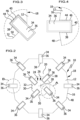
- FIG. 1 shows a simplified schematic representation of an advantageous embodiment of a fuel cell device according to the invention, designated overall by the reference numeral 10.
- the fuel cell device 10 is referred to below in simplified terms as device 10.
- the device 10 comprises a plurality of fuel cells 12 arranged in stacks one above the other, which are preferably designed identically.
- the fuel cells are PEM fuel cells (polymer electrolyte fuel cells), in which hydrogen reacts with oxygen to produce water, waste heat and electrical energy.
- any supplies for hydrogen and oxygen and/or electrical lines for dissipating the electrical energy that occurs during the reaction are any supplies for hydrogen and oxygen and/or electrical lines for dissipating the electrical energy that occurs during the reaction.
- the oxygen can be taken from the surrounding medium, in this case air, and no separate supply is required.
- the fuel cells 12 are stacked one above the other along a stacking direction 14 and are arranged such that the respective outer edges of the fuel cells 12 are aligned with one another and a uniform outer surface 16 is formed on the outside.
- the fuel cell stack 18 formed by the fuel cells 12 has a first end side 20 and a second end side 22.
- the end sides 20, 22 are opposite end sides of the fuel cell stack 18.
- the fuel cell stack 18 has a recess 24 that passes through at least a portion, preferably all, of the fuel cells 12 in the stacking direction 14.
- the recess 24 is formed as a through-opening 26, which in the present case advantageously extends from the first end side 20 to the second end side 22.
- the through opening 26 is formed centrally in the fuel cell stack 18 and runs along the stack direction 14, which defines an axis 28 of the fuel cell stack 18.
- a respective fuel cell 12 is designed in a ring shape and has a central through-opening 30.
- the through-openings 30 are aligned with one another and thus form the through-opening 26.
- An inner peripheral surface 32 of the fuel cell stack 18 encloses the through opening 26.
- the device 10 can be cooled convectively for cooling and setting an optimal operating point.
- cooling air is used which flows around the fuel cell stack 18.
- the cooling air can flow through the through opening 26.
- the device 10 has at least one heat-conducting element 34, which is arranged in thermal contact with the fuel cells 12 in the recess 24 and in particular the through-opening 26.
- heat conducting elements 34 are provided on the inner circumferential surface 32.
- several heat conducting elements 34 are also provided on the outer surface 16. It is advantageous that the heat conducting elements 34 in the through-opening 26 and on the outer surface 16 are designed identically. In the device 10, all heat conducting elements 34 are even designed identically.
- the heat conducting elements 34 are designed as heat pipes 36.
- a heat transfer medium is accommodated in the heat pipes 36, which evaporates while absorbing heat and condenses again elsewhere.
- a continuous saturated steam region is formed in the heat pipe 36, which promotes an essentially constant temperature of the heat pipe 36.
- the heat pipes 36 are cooled convectively by the flowing air, whereby heat is effectively removed from the fuel cell stack 18 and a largely homogeneous temperature distribution can be achieved within a respective fuel cell 12. Due to the uniform temperature of the heat pipes 36, there is the advantage that no temperature gradient occurs within the fuel cell stack 18 in the stack direction 14.
- the recess 24 has respective grooves 38.
- the grooves 38 are formed by recesses 40 on a respective fuel cell 12.
- the respective groove is created by stacking the fuel cells 12 along the stacking direction 14.
- the heat pipe 36 which is strip-shaped and in particular cuboid-shaped, is dimensioned such that it can engage in the groove 38 in a form-fitting manner.
- the heat pipe 36 extends from the first end side 20 to the second end side 22.
- the heat pipe 36 engages in the groove 38 with an engagement section.
- the other section of the heat pipe 36 protrudes from the groove 38.
- the heat pipe 36 engages approximately halfway into the groove 38. This ensures, on the one hand, effective heat transfer to the heat pipe 36 and, on the other hand, effective heat dissipation as a result of the air cooling.
- Grooves 38 for receiving a respective heat pipe 36 are also formed on the jacket surface 16, which correspond in size and structure to the grooves 38 on the inner peripheral surface 32.
- the four heat pipes 36 are positioned equidistant from each other.
- an angular distance between adjacent heat pipes 36 substantially 90° with respect to the axis 28.
- the eight heat pipes 36 in this case are positioned equidistant from one another on the casing surface 16.
- An angular distance between adjacent heat pipes 36 with respect to the axis 28 is essentially 45°.
- the heat pipes 36 on the inner circumferential surface 32 and on the lateral surface 16 have their greatest extent parallel to the axis 28. Their dimension radially with respect to the axis 28 is greater than their dimension with respect to the circumferential direction around the axis 28. In this way, the heat pipes 36 protrude, with respect to an axial viewing direction in plan view of the fuel cell stack 18 ( Figure 2 ) substantially radially inward on the inner peripheral surface 32 or radially outward on the lateral surface 16.
- a contact medium 44 in the present case in the form of a layer, is provided.
- the contact medium 44 is formed, for example, by a thermally conductive paste 46 that covers the side walls and the bottom of the groove 38 and is in contact with the section of the heat pipe 36 that dips into the groove 38.
- the contact medium 44 also performs a force-locking function in that adhesion forces act on the fuel cells 12 and/or the heat pipe 36.
- thermally conductive elastomer can be used as a contact medium.
- a respective fuel cell 12 in plan view axially has a substantially octagonal outer contour 48, disregarding the grooves 38.
- the inner contour 50 is also octagonal. Both Contours 48, 50 preferably have the contour of a regular octagon and are, apart from the size, congruent to each other.
- contours 48, 50 in other advantageous embodiments of the device 10 according to the invention can differ from the shape described here.
- square, rectangular, round, in particular circular, polygonal or free-form contours are conceivable.
- FIGS 5 and 6 show advantageous embodiments of an aircraft according to the invention, designated by the reference numerals 52 and 60, respectively.
- the aircraft 52, 60 each have at least one device 10 of the type described above.
- the aircraft 52 is designed as a (jet) aircraft 54.
- the at least one device 10 is arranged in an interior space 55 which is delimited by a wall 56 of the fuselage.
- Inlet openings 57 and outlet openings 58 are arranged in the wall 56. Cooling air can flow through the inlet openings 57 into the interior 55, flow along the device 10 and through the through-opening 26 and then exit the interior 55 again through the outlet openings 58.
- the openings 57, 58 are positioned and formed in such a way that the aerodynamic properties of the aircraft 54 are not impaired. In the present case, this is shown on the underside or the top of the fuselage.
- the aircraft 60 is a rotary-wing aircraft 62 in the form of a helicopter.
- An interior 63 is also provided, which is delimited by a wall 64, namely the engine housing of the helicopter.
- Inlet openings 65 and outlet openings 66 are formed in the wall 64.
- the at least one device 10 is positioned below a lift-generating rotor 68 with blades 70.
- the downwash flow of the rotor 68 is used to cool the fuel cells 12 and can enter the interior 63 through the inlet opening 65 and then exit the interior 63 again through the outlet openings 66.
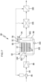
- FIG. 7 shows, with some components hidden, the conditioning device in a winter operating mode, Figure 8 in a summer operating mode.
- the conditioning device 80 comprises a chamber 82. At least one device 10 is arranged in the chamber 82. In the present case, there are two.
- a feed line 84 is provided through which the medium can be conveyed by means of a conveying device 86, for example a blower.
- a filter element 88 can be connected in the feed line 84 upstream of the chamber 82.
- the medium is fed to chamber 82.
- Oxygen contained in the air is used to react with hydrogen, which is fed via a line not shown in the drawing.
- the chamber 82 has an inlet opening 831 for the medium and an outlet opening 832 for the medium.
- the fuel cells 12 in the present case are PEM fuel cells in which, on the one hand, a certain moisture content and, on the other hand, a certain operating temperature should be set so that a preferred operating point is reached.
- Fuel cell exhaust gas is discharged from the chamber 82 via an outlet line 90.
- a suction unit 92 is provided in order to generate a negative pressure over the length of the fuel cell stack 18.
- the exhaust gas has a high water content (close to 100% relative humidity).
- a collecting device 94 is provided to remove water from the fuel cell exhaust gas.
- a droplet separator 96 is used (only in Figure 7
- the collecting device 94 has a reservoir 98 to which separated drops can be fed.
- the water is assigned to a spray device 104 via a supply line 100 of the collecting device 94, into which a pump unit 102 can be connected.
- the spray device 104 is arranged in the flow of the incoming medium upstream of the device 10, so that the medium is moistened.
- the medium heated after passing through the fuel cell stack 18 passes through a cooling device 106, which can be used optionally in winter operation, to a heating device 108.
- the medium can be heated to the desired operating temperature.
- the drive for the conveying device 86, the suction unit 92, the pumping unit 102, the cooling device 106, the heating device 108 and internal units of the devices 10 can be operated electrically by means of the energy of the devices 10.
- the conditioning device 80 in the chamber 82 can simultaneously heat the medium to be conditioned and humidify the membranes of the fuel cells 12.
- Figure 9 shows the process in winter operating mode as an example, where the temperature (in °C) is plotted against the humidity of the medium (in kg water/kg air).
- the curve marked with reference number 110 describes the equilibrium curve for 100% relative humidity
- the curve marked with reference number 112 describes the equilibrium state for 50% relative humidity.
- a conventional air conditioning system must first be preheated to point B, then humidified to point C and finally reheated to point D (dotted curve 114).
- the preheating step A-B and the humidification step B-C can be carried out simultaneously in the chamber 82, which is shown by the solid curve 116.
- the conditioning device 80 also has the advantage over a conventional air conditioning system that the desired operating point D is reached more quickly.
- the medium to be conditioned and in particular cooled is supplied via a separate supply line 118.
- a conveyor device 86 and a filter element 88 can be connected.
- the medium reaches the cooling device 106 via the supply line 118.
- the cooling device 106 is preferably an air conditioning unit 120 operating according to the heat pump principle.
- the fuel cell exhaust gas which is extracted from the chamber 82 via the outlet line 90, reaches the cooling device 106.
- the cooling device 106 forms part of the collection device 94.
- the water contained in the exhaust gas condenses in the cooling device 106, for example on an air cooler.
- the water is fed to the reservoir 98 via a line 122, into which a pump unit 124 can be connected. From there, it can be used to humidify the medium entering the chamber 82, as described above.
- the medium entering the chamber 82 is a process medium which is heated after flowing through and around the devices 10 and is discharged into the atmosphere, for example, via a discharge line 126.
- the medium to be conditioned is supplied via the supply line 118.
- this air is dehumidified and cooled in a manner known per se. If necessary, reheating can take place in the heating device 108.
- Figure 10 shows the temperature as a function of humidity for the summer operating mode according to Figure 8 .
- the warm and moderately humid air according to starting point A is cooled and dehumidified in the cooling device 106 along the curve 116 (BC).
- the cooled outside air is almost saturated with 100% relative humidity (B).
- B By mixing with room air or using the heating device 108, the temperature can be adjusted to point C, whereby the relative humidity drops again.
Landscapes
- Engineering & Computer Science (AREA)
- Chemical & Material Sciences (AREA)
- Life Sciences & Earth Sciences (AREA)
- Manufacturing & Machinery (AREA)
- Sustainable Development (AREA)
- Sustainable Energy (AREA)
- Chemical Kinetics & Catalysis (AREA)
- Electrochemistry (AREA)
- General Chemical & Material Sciences (AREA)
- Fuel Cell (AREA)
- Combustion & Propulsion (AREA)
Description
- Die vorliegende Erfindung betrifft eine Brennstoffzellenvorrichtung.
- Außerdem betrifft die vorliegende Erfindung ein Fahrzeug, insbesondere ein Luftfahrzeug, mit einer Brennstoffzellenvorrichtung.
- Ferner betrifft die vorliegende Erfindung eine Konditionierungsvorrichtung für ein gasförmiges Medium, insbesondere Luft, mit einer Brennstoffzellenvorrichtung.
- Es sind Brennstoffzellenvorrichtungen bekannt, bei denen elektrische Energie durch die Reaktion von Wasserstoff und Sauerstoff, insbesondere Luftsauerstoff, erzeugt wird. Hierzu zählen beispielsweise Polymerelektrolyt-(PEM-) Brennstoffzellen. Um in Hinblick auf eine sinnvolle Anwendung eine konstantere elektrische Spannung zu erzeugen, ist die Brennstoffzelle vorzugsweise gekühlt, um eine möglichst konstante Betriebstemperatur einzuhalten. Von Bedeutung ist für PEM-Brennstoffzellen ferner die Einhaltung einer bestimmten Feuchte der Membran für die Einhaltung des Betriebspunktes.
- Für Kühlzwecke ist es bekannt, ein flüssiges Wärmeträgermedium durch die Brennstoffzellen zu pumpen und die Kühlleistung zum Beispiel anhand einer Vorlauftemperatur anzupassen. Die Flüssigkeitskühlung erfordert einen erheblichen operativen Aufwand. Es ist beispielsweise ein Wärmetauscher vorzusehen, der räumlich entfernt von der Brennstoffzellenvorrichtung positioniert ist.
- Andere Kühlkonzepte setzen auf eine freie Anströmung der Brennstoffzellenvorrichtung, was jedoch zu einer häufig unzureichenden Kühlleistung führt.
- Bekannt ist es auch, die Brennstoffzelle über den kathodischen Luftstrom zu kühlen, der den für die Reaktion erforderlichen Sauerstoff enthält. Zu diesem Zweck wird ein Kompressor eingesetzt, was den Wirkungsgrad der Brennstoffzellenvorrichtung verringert. Darüber hinaus führt der durch die Kühllast erhöhte und für unterschiedliche Betriebsbedingungen veränderliche Sauerstoffüberschuss zu einem veränderten Betriebspunkt und damit nicht-optimalen Bedingungen für den Betrieb der Brennstoffzellen.
- Brennstoffzellenvorrichtungen finden beispielsweise Anwendung in Fahrzeugen, insbesondere Luftfahrzeugen. Die beiden erstgenannten Kühlkonzepte weisen in diesem Zusammenhang den Nachteil auf, dass Lufteinlässe für einen einstellbaren Luftvolumenstrom für den Wärmetauscher oder die Brennstoffzellenvorrichtung vorgesehen sein müssen. Dies ist nachteilig, da der Widerstand des Luftfahrzeuges gesteigert wird. Dennoch erweisen sich diese beiden erstgenannten Konzepte als vorteilhafter als das dritte Konzept, denn in diesem Fall nimmt der Wirkungsgrad der Brennstoffzellenvorrichtung ab.
- Wünschenswert ist die Nutzung der Abwärme der Brennstoffzellenvorrichtung, zum Beispiel für klimatechnische Anwendungen oder für interne Prozesse. Zu Letzteren zählt beispielsweise die Verdampfung flüssig gelagerten Wasserstoffs, der für den Betrieb erforderlich ist.
- Die
KR 2009-0006344 A - Weitere Brennstoffzellenvorrichtungen mit Brennstoffzellenstapeln und diese durchsetzenden Öffnungen, durch die hindurch Reaktanden oder eine Kühlflüssigkeit strömen können, sind in der
US 2019/0140289 A1 und in derUS 2004/0053108 A1 offenbart. - Aufgabe der vorliegenden Erfindung ist es, eine Brennstoffzellenvorrichtung mit verbesserten Kühleigenschaften bereitzustellen.
- Diese Aufgabe wird durch eine erfindungsgemäße Brennstoffzellenvorrichtung mit den Merkmalen von Anspruch 1 gelöst.
- Der Brennstoffzellenstapel umfasst innenseitig eine und insbesondere mindestens eine Ausnehmung. Zu diesem Zweck ist vorzugsweise vorgesehen, dass zumindest ein Teil der Brennstoffzellen ringförmig ausgestaltet ist. In der Ausnehmung ist ein Wärmeleitelement angeordnet. Auf diese Weise kann Wärme von den Brennstoffzellen an das Wärmeleitelement übertragen werden. Durch Konvektion kann das Wärmeleitelement gekühlt und Wärme abgeführt werden. Es zeigt sich, dass die Anordnung des mindestens einen Wärmeleitelementes innenliegend im Brennstoffzellenstapel zu vorteilhaften Kühleigenschaften führt.
- Als vorteilhaft erweist es sich, dass das mindestens eine Wärmeleitelement über ein thermisch leitfähiges Kontaktmedium indirekt in Wärmekontakt mit dem Brennstoffzellenstapel steht, wobei das Kontaktmedium vorzugsweise schichtförmig gebildet ist. Beispielsweise ist als Kontaktmedium eine Wärmeleitpaste oder ein thermisch leitfähiges Elastomer vorgesehen, über die/das die Wärmeübertragung auf das Wärmeleitelement erfolgt.
- Die Ausnehmung ist vorteilhafterweise eine Durchgangsöffnung von einer ersten Endseite des Brennstoffzellenstapels bis zu einer zweiten Endseite des Brennstoffzellenstapels. Dabei bildet der Brennstoffzellenstapel vorzugsweise einen Hohlzylinder aus, günstigerweise einen senkrechten Hohlzylinder.
- Die Durchgangsöffnung weist den Vorteil auf, dass der Brennstoffzellenstapel von einer Kühlluftströmung durchströmt werden kann und Wärme besonders wirksam abgeführt werden kann.
- Zur Ausbildung der Durchgangsöffnung ist beispielsweise vorgesehen, dass die Brennstoffzellen jeweils ringförmig ausgestaltet sind und mit einem äußeren Rand gemeinsam eine mantelförmige Außenumfangsfläche des Brennstoffzellenstapels bilden und mit einem inneren Rand gemeinsam eine die Ausnehmung einfassende Innenumfangsfläche des Brennstoffzellenstapels.
- Günstig ist es, wenn sich das mindestens eine Wärmeleitelement entlang der gesamten oder im Wesentlichen gesamten Ausnehmung erstreckt. Dabei ist es insbesondere von Vorteil, wenn sich das Wärmeleitelement von der ersten Endseite bis zur zweiten Endseite des Brennstoffzellenstapels erstreckt.
- Das mindestens eine Wärmeleitelement ist vorteilhafterweise an einer Innenumfangsfläche des Brennstoffzellenstapels angeordnet, die die Ausnehmung einfasst. Durch die Anordnung an der Innenumfangsfläche kann ein besonders guter thermischer Kontakt des mindestens einen Wärmeleitelementes mit dem Brennstoffzellenstapel sichergestellt werden.
- Von Vorteil ist es, wenn das Wärmeleitelement ein konvektiv gekühltes Wärmeleitelement ist. Die konstruktive Ausgestaltung der Brennstoffzellenvorrichtung kann dadurch besonders einfach gehalten werden. Diese wird zum Beispiel von Kühlluft umströmt. Kühlluft kann in die Ausnehmung einströmen und, zum Beispiel im Fall einer Durchgangsöffnung, den Brennstoffzellenstapel durchströmen.
- Bei einer bevorzugten Ausführungsform ist das mindestens eine Wärmeleitelement beispielsweise als Wärmerohr (Heatpipe) ausgestaltet. Das Wärmerohr weist einen umschlossenen Aufnahmeraum für ein Wärmeträgermedium auf, das einerseits verdampfen und andererseits kondensieren kann. Der Wärmeträger befindet sich dabei im Wesentlichen vollständig im Sattdampfbereich, so dass das Wärmerohr eine im Wesentlichen konstante Temperatur aufweist. Wärme kann über das Wärmerohr besonders effizient abgeführt werden. Ein Temperaturgradient über die Länge des Wärmerohres kann vorzugsweise vermieden werden.
- Von Vorteil ist es, wenn die Brennstoffzellenvorrichtung an einer außenseitigen Mantelfläche des Brennstoffzellenstapels mindestens ein Wärmeleitelement in thermischem Kontakt mit den Brennstoffzellen aufweist. Auf diese Weise besteht die Möglichkeit, Wärme von der Mantelfläche abzuführen und die Brennstoffzellen gezielter zu kühlen. Dies begünstigt eine möglichst gleichmäßige Temperaturverteilung im Brennstoffzellenstapel.
- Günstigerweise ist das außenseitig angeordnete Wärmeleitelement konvektiv gekühlt und/oder als Wärmerohr (Heatpipe) ausgestaltet. Das Wärmeleitelement erstreckt sich günstigerweise von einer ersten Endseite bis zu einer zweiten Endseite des Brennstoffzellenstapels.
- Vorzugsweise ist das mindestens eine Wärmeleitelement, in der Ausnehmung und/oder an der Mantelfläche, parallel zur Stapelrichtung ausgerichtet.
- Das mindestens eine Wärmeleitelement ist bei einer bevorzugten Ausführungsform der Erfindung vorzugsweise quaderförmig und/oder längserstreckt ausgebildet.
- Bei Vorhandensein einer Mehrzahl von Wärmeleitelementen sind diese vorzugsweise parallel zueinander ausgerichtet.
- Günstig ist es, wenn eine Mehrzahl von Wärmeleitelementen in der Ausnehmung angeordnet ist. Dies begünstigt die Wärmeabfuhr vom Brennstoffzellenstapel an dessen an die Ausnehmung grenzenden Seite.
- In entsprechender Weise ist es von Vorteil, wenn eine Mehrzahl von Wärmeleitelementen an einer außenseitigen Mantelfläche des Brennstoffzellenstapels angeordnet ist, um die Wärmeabfuhr an der Mantelfläche zu begünstigen, im Hinblick auf eine möglichst homogene Temperaturverteilung in den Brennstoffzellen.
- Die Wärmeleitelemente sind vorzugsweise identisch ausgestaltet, insbesondere diejenigen in der Ausnehmung und/oder diejenigen an der Mantelfläche und besonders vorteilhaft alle Wärmeleitelemente insgesamt.
- Die Wärmeleitelemente sind vorteilhafterweise in Umfangrichtung des Brennstoffzellenstapels äquidistant an einer die Ausnehmung einfassenden Innenumfangsfläche und/oder an der außenseitigen Mantelfläche angeordnet. Die gleichmäßige Anordnung begünstigt die Wärmeabfuhr von den Brennstoffzellen über die Wärmeleitelemente.
- Bei einer bevorzugten Ausführungsform sind an der Innenumfangsfläche des Brennstoffzellenstapels beispielsweise vier Wärmeleitelemente vorgesehen. An der außenseitigen Mantelfläche können bei einer bevorzugten Ausführungsform beispielsweise acht Wärmeleitelemente vorgesehen sein.
- Vorgesehen sein kann, dass einem jeweiligen innenseitig angeordneten Wärmeleitelement in radialer Richtung ein außenseitig an der Mantelfläche gegenüberliegendes Wärmeleitelement zugeordnet ist. "Radial" ist vorliegend auf eine vom Brennstoffzellenstapel definierte Achse bezogen aufzufassen.
- Von Vorteil ist es, wenn die Ausnehmung in den Brennstoffzellen in Stapelrichtung verlaufend und/oder eine Mantelfläche des Brennstoffzellenstapels mindestens eine Nut umfasst, in die das mindestens eine Wärmeleitelement teilweise und vorzugsweise mit Formschluss eingreift. An der Innenumfangsfläche können die Brennstoffzellen eine jeweilige Aussparung umfassen. Durch die Stapelung der Brennstoffzellen übereinander entsteht infolgedessen eine Nut. Alternativ oder ergänzend kann mindestens eine Nut an der außenseitigen Mantelfläche gebildet sein. Das mindestens eine Wärmeleitelement greift in die Nut ein und erstreckt sich vorteilhafterweise entlang der gesamten oder im Wesentlichen gesamten Erstreckung der Nut. Durch den Eingriff in die Nut wird die Abgabe von Wärme vom Brennstoffzellenstapel an das Wärmeleitelement begünstigt. Der aus der Nut herausragende Abschnitt des Wärmeleitelementes kann zur Wärmeabfuhr bevorzugt konvektiv gekühlt werden.
- Beispielsweise ist vorgesehen, dass das mindestens eine Wärmeleitelement ungefähr zur Hälfte in die Nut eingreift.
- Über den thermischen Kontakt hinaus weist das Kontaktmedium vorteilhafterweise eine Funktion zur kraftschlüssigen Verbindung des Wärmeleitelementes mit dem Brennstoffzellenstapel auf.
- Als vorteilhaft erweist es sich zum Beispiel, wenn die Brennstoffzellen in Draufsicht in Stapelrichtung eine oktagonale Außenkontur aufweisen, insbesondere unter Nichtberücksichtigung etwaiger Aussparungen für die Nut(en).
- Günstigerweise weist die Ausnehmung in Draufsicht in Stapelrichtung eine mit der Kontur der Brennstoffzellen übereinstimmenden Kontur auf, insbesondere unter Nichtberücksichtigung etwaiger Aussparungen für die Nut(en). Dies erweist sich als vorteilhaft für den Wärmetransport und die Kühlung des Brennstoffzellenstapels, insbesondere bei Anordnung von Wärmeleitelementen innenseitig in der Ausnehmung und außenseitig an der Mantelfläche des Brennstoffzellensta pels.
- Die Kontur der Ausnehmung ist vorteilhafterweise kongruent mit der Kontur der Brennstoffzellen, insbesondere unter Nichtberücksichtigung etwaiger Aussparungen für die Nut(en).
- Die Brennstoffzellen sind bei einer bevorzugten Ausführungsform PEM-Brennstoffzellen.
- Wie eingangs erwähnt, betrifft die vorliegende Erfindung auch ein Fahrzeug. Aufgabe der vorliegenden Erfindung ist es, ein Fahrzeug mit einer Brennstoffzellenvorrichtung und Nutzungsmöglichkeit für deren Abwärme bereitzustellen.
- Diese Aufgabe wird durch ein erfindungsgemäßes Fahrzeug gelöst, insbesondere Luftfahrzeug, umfassend mindestens eine Brennstoffzellenvorrichtung der vorstehend genannten Art und einen von einer Wandung begrenzten Innenraum, in dem die mindestens eine Brennstoffzellenvorrichtung angeordnet ist, wobei die Wandung mindestens eine Eintrittsöffnung für Kühlluft aufweist und in den Innenraum eintretende Kühlluft die mindestens eine Brennstoffzellenvorrichtung durch Konvektion kühlt.
- Die Vorteile, die bereits im Zusammenhang mit der erfindungsgemäßen Brennstoffzellenvorrichtung oder vorteilhafter Ausführungsformen erläutert wurden, können bei dem Fahrzeug ebenfalls erzielt werden. Diesbezüglich kann auf die voranstehenden Ausführungen verwiesen werden.
- Das Fahrzeug ist beispielsweise ein Luftfahrzeug wie ein Flugzeug, in dessen Innenraum Abwärme der Brennstoffzellenvorrichtung für interne Prozesse und/oder für Klimatisierungszwecke eingesetzt werden kann. Kühlluft kann durch eine Eintrittsöffnung, beispielsweise des Rumpfes, eintreten und den Brennstoffzellenstapel kühlen. Es sind insbesondere keine zusätzlichen Bauteile wie Wärmeüberträger erforderlich, so dass der Formwiderstand des Luftfahrzeugs nicht beeinträchtigt ist.
- Bei einer andersartigen Ausführungsform ist das Luftfahrzeug zum Beispiel ein Drehflügler, dessen Abluftstrom den Kühlluftstrom für die Brennstoffzellenvorrichtung ausbildet, wobei diese unterhalb der Drehflügel positioniert ist.
- Wie eingangs erwähnt, betrifft die vorliegende Erfindung auch eine Konditionierungsvorrichtung. Aufgabe der vorliegenden Erfindung ist es, eine Konditionierungsvorrichtung mit mindestens einer Brennstoffzellenvorrichtung unter Nutzung des Brennstoffzellenabgases bereitzustellen.
- Hierbei wird angenommen, dass das Brennstoffzellenabgas Wasser enthält, in Folge der Reaktion von Wasserstoff und Sauerstoff.
- Diese Aufgabe wird durch eine erfindungsgemäße Konditionierungsvorrichtung für ein gasförmiges Medium gelöst, insbesondere Luft, umfassend mindestens eine Brennstoffzellenvorrichtung der vorstehend genannten Art, eine Kammer, in der die mindestens eine Brennstoffzellenvorrichtung angeordnet ist, eine Eintrittsöffnung der Kammer für das gasförmige Medium, eine Austrittsöffnung der Kammer für das gasförmige Medium und eine Sammeleinrichtung mit einem Pump- oder Saugaggregat, um Wasser enthaltendes Abgas der mindestens einen Brennstoffzellenvorrichtung aus der Kammer zu entfernen und dem Abgas der mindestens einen Brennstoffzellenvorrichtung Wasser zu entziehen, und eine Zuführleitung, mit der dem Abgas entzogenes Wasser der Kammer strömungsaufwärts der mindestens einen Brennstoffzellenvorrichtung zuführbar ist.
- Bei einer derartigen Konditionierungsvorrichtung kann die Kammer mit dem Medium beaufschlagt werden. Mittels des zugeführten Wassers wird das Medium befeuchtet. Durch die Feuchtigkeit wird das Betriebsverhalten der Brennstoffzellenvorrichtung verbessert, insbesondere bei PEM-Brennstoffzellen. Das Pump- oder Saugaggregat ermöglicht es, die Brennstoffzellenvorrichtung mit Über- oder Unterdruck zu beaufschlagen, um das Wasser enthaltende Abgas aus der Kammer zu entfernen. Über die Sammeleinrichtung kann das Wasser auskondensiert und der Zuführleitung zugeführt werden. Die Konditionierungsvorrichtung bietet den Vorteil, dass gleichzeitig eine Kühlung des Brennstoffzellenstapels und eine Befeuchtung zur Verbesserung des Betriebspunktes erzielt werden kann.
- Die vorstehend beschriebene Konditionierungsvorrichtung ermöglicht es, das durch die Kammer geführte Medium mittels der Abwärme der Brennstoffzellenvorrichtung zu erwärmen. In diesem Fall können das zu konditionierende Medium und das Prozessmedium für die Kühlung der Brennstoffzellenvorrichtung übereinstimmen. Dies ist beispielsweise bei einem Winterbetrieb der Konditionierungsvorrichtung der Fall.
- Günstig ist es, wenn die Konditionierungsvorrichtung eine Kühleinrichtung umfasst, der über eine Zuführleitung das zu konditionierende Medium zuführbar ist, wobei die Kühleinrichtung einen Teil der Sammeleinrichtung ausbildet, in dem das Wasser enthaltende Abgas der Kühleinrichtung zugeführt und darin kondensiert und der Kammer zugeführt wird.
- Bei einer derartigen Ausführungsform können das zu konditionierende Medium und das Prozessmedium auseinander fallen. Das zu konditionierende Medium wird der Kühleinrichtung zugeführt, beispielsweise ein nach dem Prinzip der Wärmepumpeneinrichtung arbeitendes Klimagerät. Darin kann das zu konditionierende Medium entfeuchtet und gekühlt werden. Das Wasser enthaltende Abgas der Brennstoffzellenvorrichtung kann der Kühleinrichtung ebenfalls zugeführt werden, wodurch durch Abkühlung Wasser auskondensiert, welches der Kammer zur Befeuchtung zugeführt werden kann.
- Vorstehend beschriebene Ausführungsform der Klimatisierungsvorrichtung beschreibt insbesondere deren Sommerbetrieb.
- Günstigerweise umfasst die Konditionierungsvorrichtung eine mittels Energie der mindestens einen Brennstoffzellenvorrichtung elektrisch betriebene Heizeinrichtung, der das zu konditionierende gasförmige Medium zuführbar ist. Strömungsabwärts der Kammer bzw. der Kühleinrichtung kann das Medium für Winterbetrieb und gegebenenfalls Sommerbetrieb aufgeheizt werden. Günstig ist die Nutzung der elektrischen Energie der mindestens einen Brennstoffzellenvorrichtung.
- Es versteht sich, dass die elektrische Energie der mindestens einen Brennstoffzellenvorrichtung zum Betreiben weiterer Aggregate der Konditionierungsvorrichtung eingesetzt werden kann. Hierzu zählen insbesondere Antriebsmotoren für Fördereinrichtungen wie Gebläse zum Bereitstellen von Luftströmen, Fördereinrichtungen wie Saug- oder Pumpaggregate, zum Beispiel zur Erzeugung des Abgasstroms und/oder Aggregate zu internen Versorgung der Brennstoffzellenvorrichtung.
- Weitere vorteilhafte Ausführungsformen der Konditionierungsvorrichtung ergeben sich durch vorteilhafte Ausführungsformen der erfindungsgemäßen Brennstoffzellenvorrichtung.
- Die nachfolgende Beschreibung bevorzugter Ausführungsformen der Erfindung dient im Zusammenhang mit der Zeichnung der näheren Erläuterung der Erfindung. Es zeigen:
- Figur 1:
- eine schematische perspektivische Ansicht einer erfindungsgemäßen Brennstoffzellenvorrichtung in vereinfachter Darstellung;
- Figur 2:
- eine Draufsicht auf die Brennstoffzellenvorrichtung in
Figur 1 ; - Figur 3:
- eine vergrößerte Darstellung von Detail A in
Figur 2 ; - Figur 4:
- eine vergrößerte Darstellung von Detail B in
Figur 2 ; - Figur 5:
- eine schematische Darstellung eines erfindungsgemäßen Fahrzeugs, ausgestaltet als Luftfahrzeug und insbesondere als Flugzeug;
- Figur 6:
- eine schematische Darstellung eines erfindungsgemäßen Fahrzeugs, ausgestaltet als Luftfahrzeug und insbesondere als Drehflügler;
- Figur 7:
- eine bevorzugte Ausführungsform einer erfindungsgemäßen Konditionierungsvorrichtung in einem Winterbetrieb;
- Figur 8:
- die Konditionierungsvorrichtung aus
Figur 7 in einem Sommerbetrieb; - Figur 9:
- schematisch ein Temperatur-Feuchtigkeit-Diagramm für den Winterbetrieb gemäß
Figur 7 ; und - Figur 10:
- schematisch ein Temperatur-Feuchtigkeit-Diagramm für den Sommerbetrieb gemäß
Figur 8 . -
Figur 1 zeigt in schematischer vereinfachter Darstellung eine insgesamt mit dem Bezugszeichen 10 belegte vorteilhafte Ausführungsform einer erfindungsgemäßen Brennstoffzellenvorrichtung. Die Brennstoffzellenvorrichtung 10 wird nachfolgend vereinfacht als Vorrichtung 10 bezeichnet. - Die Vorrichtung 10 umfasst eine Mehrzahl von stapelweise übereinander angeordneten Brennstoffzellen 12, die vorzugsweise identisch ausgestaltet sind. Im vorliegenden Fall sind die Brennstoffzellen PEM-Brennstoffzellen (Polymerelektrolyt-Brennstoffzelle), bei denen Wasserstoff mit Sauerstoff unter Entstehung von Wasser, Abwärme und elektrischer Energie reagiert.
- Nicht dargestellt in der Zeichnung sind etwaige Zuführungen für Wasserstoff und Sauerstoff und/oder elektrische Leitungen zum Ableiten der elektrischen Energie, die bei der Reaktion auftritt. Vorgesehen ist jedoch günstigerweise, dass der Sauerstoff dem Umgebungsmedium, vorliegend Luft, entnommen werden kann und keine gesonderte Zuführung erforderlich ist.
- Die Brennstoffzellen 12 sind entlang einer Stapelrichtung 14 übereinander gestapelt und dabei so angeordnet, dass die jeweiligen äußeren Ränder der Brennstoffzellen 12 miteinander fluchten und außenseitig eine einheitliche Mantelfläche 16 gebildet ist.
- Der durch die Brennstoffzellen 12 gebildete Brennstoffzellenstapel 18 weist eine erste Endseite 20 auf und eine zweite Endseite 22. Die Endseiten 20, 22 sind einander abgewandte Endseiten des Brennstoffzellenstapels 18.
- Der Brennstoffzellenstapel 18 weist gemäß der vorliegenden Erfindung eine zumindest einen Teil, vorzugsweise alle, der Brennstoffzellen 12 in Stapelrichtung 14 durchsetzende Ausnehmung 24 auf. Die Ausnehmung 24 ist gebildet als Durchgangsöffnung 26, die sich vorliegend vorteilhaft von der ersten Endseite 20 bis zur zweiten Endseite 22 erstreckt.
- Die Durchgangsöffnung 26 ist zentral im Brennstoffzellenstapel 18 gebildet und verläuft entlang der Stapelrichtung 14, die eine Achse 28 des Brennstoffzellenstapels 18 definiert.
- Zur Bildung der Ausnehmung 24 und insbesondere Durchgangsöffnung 26 ist eine jeweilige Brennstoffzelle 12 ringförmig ausgestaltet und weist zentral eine Durchgangsöffnung 30 auf. Die Durchgangsöffnungen 30 fluchten miteinander und bilden dadurch die Durchgangsöffnung 26.
- Eine Innenumfangsfläche 32 des Brennstoffzellenstapels 18 fasst die Durchgangsöffnung 26 ein.
- Die Vorrichtung 10 kann zum Kühlen und Einstellen eines optimalen Betriebspunktes konvektiv gekühlt werden. Dabei kommt insbesondere Kühlluft zum Einsatz, die den Brennstoffzellenstapel 18 umströmt. Insbesondere besteht auch die Möglichkeit, dass die Kühlluft durch die Durchgangsöffnung 26 strömen kann.
- Zur Steigerung der Kühlleistung weist die Vorrichtung 10 mindestens ein Wärmeleitelement 34 auf, das in thermischem Kontakt mit den Brennstoffzellen 12 in der Ausnehmung 24 und insbesondere Durchgangsöffnung 26 angeordnet ist.
- Im vorliegenden Fall sind an der Innenumfangsfläche 32 mehrere Wärmeleitelemente 34 vorgesehen. Zur Steigerung der Kühlleistung sind auch an der Mantelfläche 16 mehrere Wärmeleitelemente 34 vorgesehen. Günstig ist es dabei, dass einerseits die Wärmeleitelemente 34 in der Durchgangsöffnung 26 für sich und andererseits an der Mantelfläche 16 für sich identisch ausgestaltet sind. Bei der Vorrichtung 10 sind sogar alle Wärmeleitelemente 34 identisch ausgestaltet.
- Im vorliegenden Fall sind die Wärmeleitelemente 34 als Wärmerohre 36 (Heatpipes) ausgestaltet. In den Wärmerohren 36 ist ein Wärmeträgermedium aufgenommen, das unter Aufnahme von Wärme verdampft und an anderer Stelle wieder kondensiert. Es stellt sich im Wärmerohr 36 ein durchgängiges Sattdampfgebiet ein, wodurch eine im Wesentlichen konstante Temperatur des Wärmerohrs 36 begünstigt wird. Die Wärmerohre 36 werden konvektiv durch die strömende Luft gekühlt, wodurch Wärme vom Brennstoffenzellenstapel 18 wirkungsvoll entfernt und innerhalb einer jeweiligen Brennstoffzelle 12 eine weitgehend homogene Temperaturverteilung erzielt werden kann. Aufgrund der jeweils einheitlichen Temperatur der Wärmerohre 36 besteht der Vorteil, dass kein Temperaturgradient innerhalb des Brennstoffzellenstapels 18 in der Stapelrichtung 14 auftritt.
- Zum Aufnehmen der Wärmerohre 36 weist die Ausnehmung 24 jeweilige Nuten 38 auf. Die Nuten 38 sind durch Aussparungen 40 an einer jeweiligen Brennstoffzelle 12 gebildet. Durch die Stapelung der Brennstoffzellen 12 entsteht entlang der Stapelrichtung 14 die jeweilige Nut.
- Das leistenförmig und insbesondere quaderförmig ausgestaltete Wärmerohr 36 ist so bemessen, dass es formschlüssig in die Nut 38 eingreifen kann. Dabei erstreckt sich das Wärmerohr 36 von der ersten Endseite 20 bis zur zweiten Endseite 22. Das Wärmerohr 36 greift mit einem Eingriffsabschnitt in die Nut 38 ein. Der jeweils andere Abschnitt des Wärmerohrs 36 ragt aus der Nut 38 heraus. Im vorliegenden Fall greift das Wärmerohr 36 ungefähr zur Hälfte in die Nut 38 ein. Dies sichert zum einen eine wirksame Wärmeübertragung auf das Wärmerohr 36 und zum anderen eine wirksame Wärmeabfuhr infolge der Luftkühlung.
- An der Mantelfläche 16 sind ebenfalls Nuten 38 zur Aufnahme eines jeweiligen Wärmerohrs 36 gebildet, die in Größe und Aufbau den Nuten 38 an der Innenumfangsfläche 32 entsprechen.
- An der Innenumfangsfläche 32 sind die vorliegend vier Wärmerohre 36 äquidistant zueinander positioniert. Im vorliegenden Fall beträgt ein Winkelabstand zwischen benachbarten Wärmerohren 36 im Wesentlichen 90° bezüglich der Achse 28.
- An der Mantelfläche 16 sind die vorliegend acht Wärmerohre 36 äquidistant zueinander positioniert. Ein Winkelabstand zwischen benachbarten Wärmerohren 36 bezüglich der Achse 28 beträgt im Wesentlichen 45°.
- Die Wärmerohre 36 an der Innenumfangsfläche 32 und an der Mantelfläche 16 weisen parallel zur Achse 28 ihre größte Erstreckung auf. Ihre Abmessung radial bezüglich der Achse 28 ist größer als ihre Abmessung bezüglich der Umfangsrichtung um die Achse 28. Auf diese Weise ragen die Wärmerohre 36, bezogen auf eine axiale Blickrichtung in Draufsicht auf den Brennstoffzellenstapel 18 (
Figur 2 ) im Wesentlichen radial nach innen an der Innenumfangsfläche 32 bzw. radial nach außen an der Mantelfläche 16. - Zur Verbesserung des thermischen Kontaktes zwischen den Brennstoffzellen 12 und den Wärmerohren 36 ist ein im vorliegenden Fall schichtförmiges Kontaktmedium 44 vorgesehen. Das Kontaktmedium 44 ist beispielsweise durch eine Wärmeleitpaste 46 gebildet, die die Seitenwände und den Boden der Nut 38 bedeckt und in Kontakt mit dem in die Nut 38 eintauchenden Abschnitt des Wärmerohrs 36 steht. Das Kontaktmedium 44 übt über den thermischen Kontakt hinaus auch eine kraftschlüssige Funktion aus, indem Adhäsionskräfte zu den Brennstoffzellen 12 und/oder zum Wärmerohr 36 wirken.
- Als Kontaktmedium kann alternativ beispielsweise ein thermisch leitfähiges Elastomer zum Einsatz kommen.
- Wie insbesondere
Figur 2 hervorgeht, weist eine jeweilige Brennstoffzelle 12 in Draufsicht axial vorliegend eine im Wesentlichen achteckförmige Außenkontur 48 auf, unter Nichtbeachtung der Nuten 38. - Entsprechendes gilt für die Innenkontur 50 der Brennstoffzellen 12 unter Nichtbeachtung der Nuten 38. Auch die Innenkontur 50 ist achteckförmig. Beiden Konturen 48, 50 weisen vorzugsweise die Kontur eine regelmäßigen Achtecks auf und sind, abgesehen von der Größe, zueinander kongruent.
- Es versteht sich, dass die Konturen 48, 50 bei andersartigen vorteilhaften Ausführungsformen der erfindungsgemäßen Vorrichtung 10 abweichend von der hier beschriebenen Form sein können. Beispielsweise sind quadratische, rechteckförmige, runde, insbesondere kreisrunde, polygonale oder Freiform-Konturen denkbar.
- Die
Figuren 5 und 6 zeigen mit den Bezugszeichen 52 bzw. 60 belegte vorteilhafte Ausführungsformen eines erfindungsgemäßen Luftfahrzeugs. Die Luftfahrzeuge 52, 60 weisen jeweils mindestens eine Vorrichtung 10 der vorstehend beschriebenen Art auf. - Das Luftfahrzeug 52 ist ausgestaltet als (Strahl-)Flugzeug 54. In einem Innenraum 55, der von einer Wandung 56 des Rumpfes begrenzt ist, ist die mindestens eine Vorrichtung 10 angeordnet.
- In der Wandung 56 sind Eintrittsöffnungen 57 und Austrittsöffnungen 58 angeordnet. Kühlluft kann durch die Eintrittsöffnungen 57 in den Innenraum 55 strömen, die Vorrichtung 10 entlang und durch die Durchgangsöffnung 26 durchströmen und anschließend durch die Austrittsöffnungen 58 wieder aus dem Innenraum 55 austreten.
- Auf diese Weise kann während des Fluges Umgebungsluft zum Kühlen der Brennstoffzellen 12 eingesetzt werden. Günstig ist es dabei, wenn die Öffnungen 57, 58 so positioniert und gebildet sind, dass die aerodynamischen Eigenschaften des Flugzeugs 54 nicht beeinträchtigt werden. Im vorliegenden Fall ist dies an der Unterseite bzw. der Oberseite des Rumpfes dargestellt.
- Das Luftfahrzeug 60 gemäß
Figur 6 ist ein Drehflügler 62 in Gestalt eines Hubschraubers. Dabei ist ebenfalls ein Innenraum 63 vorgesehen, der von einer Wandung 64, nämlich dem Motorgehäuse des Hubschraubers, begrenzt ist. In der Wandung 64 sind Eintrittsöffnungen 65 und Austrittsöffnungen 66 gebildet. - Im vorliegenden Fall ist die mindestens eine Vorrichtung 10 unterhalb eines Auftrieb erzeugenden Rotors 68 mit Flügeln 70 positioniert. Die Abwindströmung des Rotors 68 wird zum Kühlen der Brennstoffzellen 12 eingesetzt und kann durch die Eintrittsöffnung 65 in den Innenraum 63 eintreten und anschließend aus den Austrittsöffnungen 66 wieder aus dem Innenraum 63 austreten.
- Nachfolgend wird unter Verweis auf die
Figuren 7 bis 10 auf eine mit dem Bezugszeichen 80 belegte vorteilhafte Ausführungsform einer erfindungsgemä-ßen Konditionierungsvorrichtung für ein gasförmiges Medium, insbesondere Luft, eingegangen. Die Konditionierungsvorrichtung 80 dient zur Konditionierung und insbesondere Klimatisierung von Luft. Dabei kommt mindestens eine Vorrichtung 10 der vorstehend beschriebenen Art zum Einsatz.Figur 7 zeigt, unter Ausblendung einiger Komponenten, die Konditionierungsvorrichtung in einem Winterbetriebsmodus,Figur 8 in einem Sommerbetriebsmodus. - Die Konditionierungsvorrichtung 80 umfasst eine Kammer 82. In der Kammer 82 ist mindestens eine Vorrichtung 10 angeordnet. Vorliegend sind es derer zwei.
- Eine Zuführleitung 84 ist vorgesehen, durch die hindurch mittels einer Fördereinrichtung 86, beispielsweise eines Gebläses, das Medium förderbar ist. Ein Filterelement 88 kann der Kammer 82 vorgelagert in die Zuführleitung 84 geschaltet sein.
- Das Medium wird der Kammer 82 zugeführt. Sauerstoff, der in der Luft enthalten ist, dient zur Reaktion mit Wasserstoff, der über eine in der Zeichnung nicht dargestellte Leitung zugeführt wird.
- Die Kammer 82 weist eine Eintrittsöffnung 831 für das Medium und eine Austrittsöffnung 832 für das Medium auf.
- Die Brennstoffzellen 12 sind vorliegend PEM-Brennstoffzellen, bei denen zum einen ein bestimmter Feuchtegehalt und zum anderen eine bestimmte Betriebstemperatur eingestellt werden sollten, damit ein bevorzugter Betriebspunkt erreicht wird.
- Brennstoffzellenabgas wird über eine Ausgangsleitung 90 aus der Kammer 82 abgeführt. Zu diesem Zweck ist vorliegend ein Saugaggregat 92 vorgesehen, um über die Länge der Brennstoffzellenstapel 18 einen Unterdruck zu erzeugen. Das Abgas weist einen hohen Wassergehalt auf (nahe 100% relativer Feuchte).
- Eine Sammeleinrichtung 94 ist vorgesehen, um dem Brennstoffzellenabgas Wasser zu entziehen. Dabei kommt bei dem Winterbetriebsmodus gemäß Figur 7 ein Tropfenabscheider 96 zum Einsatz (nur in
Figur 7 dargestellt). Die Sammeleinrichtung 94 weist ein Reservoir 98 auf, dem abgeschiedene Tropfen zugeführt werden können. - Ausgehend vom Reservoir 98 wird das Wasser über eine Zuführleitung 100 der Sammeleinrichtung 94, in die ein Pumpaggregat 102 geschaltet sein kann, einer Sprüheinrichtung 104 zugeordnet. Die Sprüheinrichtung 104 ist im Strom des zuströmenden Mediums strömungsaufwärts der Vorrichtung 10 angeordnet, so dass das Medium befeuchtet wird.
- Das nach Durchgang durch die Brennstoffzellenstapel 18 erwärmte Medium gelangt durch eine im Winterbetrieb optional einsetzbare Kühleinrichtung 106 zu einer Heizeinrichtung 108. In der Heizeinrichtung 108 kann das Medium auf die gewünschte Betriebstemperatur erwärmt werden.
- Vorteilhaft ist es, dass der Antrieb für die Fördereinrichtung 86, das Saugaggregat 92, das Pumpaggregat 102, die Kühleinrichtung 106, die Heizeinrichtung 108 und interne Aggregate der Vorrichtungen 10 elektrisch mittels der Energie der Vorrichtungen 10 betrieben werden können.
- Günstig ist es, dass bei der Konditionierungsvorrichtung 80 in der Kammer 82 zugleich eine Erwärmung des zu konditionierenden Mediums und eine Befeuchtung der Membranen der Brennstoffzellen 12 durchgeführt werden kann.
-
Figur 9 zeigt beispielhaft den Vorgang im Winterbetriebsmodus, wobei die Temperatur (in °C) über der Feuchtigkeit des Mediums (in kg Wasser/kg Luft) aufgetragen ist. Die mit Bezugszeichen 110 versehene Kurve beschreibt die Gleichgewichtskurve für 100% relativer Feuchte, die mit Bezugszeichen 112 belegte Kurve den Gleichgewichtszustand für 50% relativer Feuchte. - Ausgehend von einem Ausgangspunkt A ist bei einer herkömmlichen Klimaanlage zunächst bis zum Punkt B eine Vorwärmung durchzuführen, anschließend eine Befeuchtung zum Punkt C und schließlich eine Nachwärmung zum Punkt D (gepunktete Kurve 114).
- Bei der Konditionierungsvorrichtung 80 kann demgegenüber der Schritt der Vorwärmung A-B und der Befeuchtung B-C in der Kammer 82 gleichzeitig durchgeführt werden, was durch die durchgezogene Kurve 116 dargestellt ist. Über die Vereinfachung in konstruktiver Hinsicht weist die Konditionierungsvorrichtung 80 gegenüber einer herkömmlichen Klimaanlage somit auch den Vorteil auf, dass der gewünschte Betriebspunkt D schneller erreicht wird.
- Nachfolgend wird auf den in
Figur 8 dargestellten Sommerbetriebsmodus der Konditionierungsvorrichtung 80 eingegangen. Es versteht sich, dass in denFiguren 8 bzw. 7 ausgeblendete Komponenten für den jeweils anderen Betrieb vorhanden sein können. - Im Sommerbetriebsmodus wird das zu konditionierende und insbesondere zu kühlende Medium, nämlich Luft, über eine gesonderte Zuführleitung 118 zugeführt. In die Zuführleitung 118 können ebenfalls eine Fördereinrichtung 86 und ein Filterelement 88 geschaltet sein. Das Medium gelangt über die Zuführleitung 118 zur Kühleinrichtung 106. Die Kühleinrichtung 106 ist vorzugsweise ein nach dem Wärmepumpenprinzip arbeitendes Klimagerät 120.
- Im Sommerbetrieb gelangt das Brennstoffzellenabgas, das über die Ausgangsleitung 90 der Kammer 82 entzogen wird, zur Kühleinrichtung 106. Die Kühleinrichtung 106 bildet einen Teil der Sammeleinrichtung 94.
- In der Kühleinrichtung 106, beispielsweise an einem Luftkühler, kondensiert das im Abgas enthaltene Wasser. Über eine Leitung 122, in die ein Pumpaggregat 124 geschaltet sein kann, wird das Wasser dem Reservoir 98 zugeführt. Ausgehend von dort kann es wie vorstehend beschrieben zum Befeuchten des in die Kammer 82 eintretenden Mediums eingesetzt werden.
- Abweichend vom Winterbetrieb ist das in die Kammer 82 eintretende Medium ein Prozessmedium, das nach Durch- und Umströmen der Vorrichtungen 10 erwärmt ist und über eine Abgabeleitung 126 zum Beispiel in die Atmosphäre abgelassen wird. Demgegenüber wird das zu konditionierende Medium über die Zuführleitung 118 zugeführt.
- In der Kühleinrichtung 106 wird diese Luft in an sich bekannter Weise entfeuchtet und gekühlt. Erforderlichenfalls kann ein Nachwärmen in der Heizeinrichtung 108 erfolgen.
-
Figur 10 zeigt die Temperatur als Funktion der Feuchte für den Sommerbetriebsmodus gemäßFigur 8 . Die warme und mäßig feuchte Luft gemäß Ausgangspunkt A wird in der Kühleinrichtung 106 entlang der Kurve 116 gekühlt und entfeuchtet (B-C). Die gekühlte Außenluft ist nahezu mit 100% relativer Feuchte gesättigt (B). Durch die Mischung mit Raumluft oder Einsatz der Heizeinrichtung 108 kann die Temperatur auf den Punkt C angepasst werden, wodurch die relative Feuchte wieder abfällt. -
- 10
- Brennstoffzellenvorrichtung
- 12
- Brennstoffzelle
- 14
- Stapelrichtung
- 16
- Mantelfläche
- 18
- Brennstoffzellenstapel
- 20
- erste Endseite
- 22
- zweite Endseite
- 24
- Ausnehmung
- 26
- Durchgangsöffnung
- 28
- Achse
- 30
- Durchgangsöffnung
- 32
- Innenumfangsfläche
- 34
- Wärmeleitelement
- 36
- Wärmerohr
- 38
- Nut
- 40
- Aussparung
- 44
- Kontaktmedium
- 46
- Wärmeleitpaste
- 48
- Außenkontur
- 50
- Innenkontur
- 52
- Luftfahrzeug
- 54
- Flugzeug
- 55
- Innenraum
- 56
- Wandung
- 57
- Eintrittsöffnung
- 58
- Austrittsöffnung
- 60
- Luftfahrzeug
- 62
- Drehflügler
- 63
- Innenraum
- 64
- Wandung
- 65
- Eintrittsöffnung
- 66
- Austrittsöffnung
- 68
- Rotor
- 70
- Flügel
- 80
- Konditionierungsvorrichtung
- 82
- Kammer
- 831
- Eintrittsöffnung
- 832
- Austrittsöffnung
- 84
- Zuführleitung
- 86
- Fördereinrichtung
- 88
- Filterelement
- 90
- Ausgangsleitung
- 92
- Saugaggregat
- 94
- Sammeleinrichtung
- 96
- Tropfenabscheider
- 98
- Reservoir
- 100
- Zuführleitung
- 102
- Pumpaggregat
- 104
- Sprüheinrichtung
- 106
- Kühleinrichtung
- 108
- Heizeinrichtung
- 110, 112, 114, 116
- Kurve
- 118
- Zuführleitung
- 120
- Klimagerät
- 122
- Leitung
- 124
- Pumpaggregat
- 126
- Abgabeleitung
Claims (14)
- Brennstoffzellenvorrichtung, umfassend eine Mehrzahl von in einer Stapelrichtung (14) übereinander angeordneten, einen Brennstoffzellenstapel (18) bildenden Brennstoffzellen (12), insbesondere PEM-Brennstoffzellen, wobei im Brennstoffzellenstapel (18) eine die Brennstoffzellen (12) in Stapelrichtung (14) durchsetzende Ausnehmung (24) gebildet ist und in der Ausnehmung (24) mindestens ein Wärmeleitelement (34) angeordnet ist, dadurch gekennzeichnet, dass das mindestens eine Wärmeleitelement (34) in thermischem Kontakt mit den Brennstoffzellen (12) ist, wobei das mindestens eine Wärmeleitelement (34) über ein thermisch leitfähiges Kontaktmedium (44) indirekt in Wärmekontakt mit dem Brennstoffzellenstapel (18) steht, wobei das Kontaktmedium (44) vorzugsweise schichtförmig gebildet ist.
- Brennstoffzellenvorrichtung nach Anspruch 1, dadurch gekennzeichnet, dass die Ausnehmung (24) eine Durchgangsöffnung (26) von einer ersten Endseite (20) des Brennstoffzellenstapels (18) bis zu einer zweiten Endseite (22) des Brennstoffzellenstapels (18) ist, insbesondere dass der Brennstoffzellenstapel (18) einen Hohlzylinder ausbildet.
- Brennstoffzellenvorrichtung nach Anspruch 1 oder 2, dadurch gekennzeichnet, dass sich das mindestens eine Wärmeleitelement (34) entlang der gesamten oder im Wesentlichen gesamten Ausnehmung (24) erstreckt, insbesondere von der ersten Endseite (20) bis zur zweiten Endseite (22) des Brennstoffzellenstapels (18).
- Brennstoffzellenvorrichtung nach einem der voranstehenden Ansprüche, dadurch gekennzeichnet, dass das mindestens eine Wärmeleitelement (34) an einer Innenumfangsfläche (32) des Brennstoffzellenstapels (18) angeordnet ist, der die Ausnehmung (24) einfasst.
- Brennstoffzellenvorrichtung nach einem der voranstehenden Ansprüche, dadurch gekennzeichnet, dass zumindest eines der Folgenden gilt:- das Wärmeleitelement (34) ist ein konvektiv gekühltes Wärmeleitelement (34);- das Wärmeleitelement (34) ist als Wärmerohr (36) (Heatpipe) ausgestaltet.
- Brennstoffzellenvorrichtung nach einem der voranstehenden Ansprüche, dadurch gekennzeichnet, dass die Ausnehmung (24) eine Erstreckung quer und insbesondere senkrecht zu von den Brennstoffzellen (12) jeweils definierten Ebenen aufweist.
- Brennstoffzellenvorrichtung nach einem der voranstehenden Ansprüche, dadurch gekennzeichnet, dass die Brennstoffzellenvorrichtung (10) an einer außenseitigen Mantelfläche (16) des Brennstoffzellenstapels (18) mindestens ein Wärmeleitelement (34) in thermischem Kontakt mit den Brennstoffzellen (12) aufweist.
- Brennstoffzellenvorrichtung nach einem der voranstehenden Ansprüche, dadurch gekennzeichnet, dass das mindestens eine Wärmeleitelement (34) parallel zur Stapelrichtung (14) ausgerichtet ist und/oder dass die Brennstoffzellen (12) in Draufsicht in Stapelrichtung (14) eine oktagonale Außenkontur (48) aufweisen.
- Brennstoffzellenvorrichtung nach einem der voranstehenden Ansprüche, dadurch gekennzeichnet, dass eine Mehrzahl von Wärmeleitelementen (34) in der Ausnehmung (24) und/oder eine Mehrzahl von Wärmeleitelementen (34) an einer außenseitigen Mantelfläche (16) des Brennstoffzellenstapels (18) angeordnet ist, insbesondere dass die Wärmeleitelemente (34) identisch ausgestaltet sind, vorzugsweise dass die Wärmeleitelemente (34) in Umfangsrichtung des Brennstoffzellenstapels (18) äquidistant an einer die Ausnehmung (24) einfassenden Innenumfangsfläche (32) und/oder an der außenseitigen Mantelfläche (16) angeordnet sind.
- Brennstoffzellenvorrichtung nach einem der voranstehenden Ansprüche, dadurch gekennzeichnet, dass die Ausnehmung (24) und/oder eine Mantelfläche (16) des Brennstoffzellenstapels (18) in den Brennstoffzellen (12) in Stapelrichtung (14) verlaufend mindestens eine Nut (38) umfasst, in die das mindestens eine Wärmeleitelement (34) teilweise und vorzugsweise mit Formschluss eingreift, wobei das mindestens eine Wärmeleitelement (34) vorzugsweise ungefähr zur Hälfte in die Nut (38) eingreift.
- Brennstoffzellenvorrichtung nach einem der voranstehenden Ansprüche, dadurch gekennzeichnet, dass die Ausnehmung (24) in Draufsicht in Stapelrichtung (14) eine mit der Kontur (48) der Brennstoffzellen (12) übereinstimmende Kontur (50) aufweist und insbesondere kongruent zu dieser ist.
- Fahrzeug, insbesondere Luftfahrzeug (52; 60), umfassend mindestens eine Brennstoffzellenvorrichtung (10) nach einem der voranstehenden Ansprüche und einen von einer Wandung (56; 64) begrenzten Innenraum (55; 63), in dem die mindestens eine Brennstoffzellenvorrichtung (10) angeordnet ist, wobei die Wandung (56; 64) mindestens eine Eintrittsöffnung (57; 65) für Kühlluft aufweist und in den Innenraum (55; 63) eintretende Kühlluft die mindestens eine Brennstoffzellenvorrichtung (10) durch Konvektion kühlt.
- Konditionierungsvorrichtung für ein gasförmiges Medium, insbesondere Luft, umfassend mindestens eine Brennstoffzellenvorrichtung (10) nach einem der Ansprüche 1 bis 11, eine Kammer (82), in der die mindestens einen Brennstoffzellenvorrichtung (10) angeordnet ist, eine Eintrittsöffnung (831) der Kammer (82) für das gasförmige Medium, eine AustrittsÖffnung (832) der Kammer (82) für das gasförmige Medium, eine Sammeleinrichtung (94) mit einem Pump- oder Saugaggregat (92), um Wasser enthaltendes Abgas der mindestens einen Brennstoffzellenvorrichtung (10) aus der Kammer (82) zu entfernen und dem Abgas der mindestens einen Brennstoffzellenvorrichtung (10) Wasser zu entziehen, und eine Zuführleitung (100), mit der dem Abgas entzogenes Wasser der Kammer (82) strömungsaufwärts der mindestens einen Brennstoffzellenvorrichtung (10) zuführbar ist.
- Konditionierungsvorrichtung nach Anspruch 13, dadurch gekennzeichnet, dass die Konditionierungsvorrichtung (80) zumindest eines der Folgenden umfasst:- eine Kühleinrichtung (106), der über eine Zuführleitung (118) das zu konditionierende Medium zuführbar ist, wobei die Kühleinrichtung (108) einen Teil der Sammeleinrichtung (94) ausbildet, indem das Wasser enthaltende Abgas der Kühleinrichtung (108) zugeführt und darin kondensiert und der Kammer (82) zugeführt wird;- eine mittels Energie der mindestens einen Brennstoffzellenvorrichtung (10) elektrisch betriebene Heizeinrichtung (108), der das zu konditionierende gasförmige Medium zuführbar ist.
Applications Claiming Priority (1)
| Application Number | Priority Date | Filing Date | Title |
|---|---|---|---|
| DE102019129336.7A DE102019129336A1 (de) | 2019-10-30 | 2019-10-30 | Brennstoffzellenvorrichtung, Fahrzeug mit Brennstoffzellenvorrichtung und Konditionierungsvorrichtung mit Brennstoffzellenvorrichtung |
Publications (2)
| Publication Number | Publication Date |
|---|---|
| EP3817112A1 EP3817112A1 (de) | 2021-05-05 |
| EP3817112B1 true EP3817112B1 (de) | 2024-05-01 |
Family
ID=73037883
Family Applications (1)
| Application Number | Title | Priority Date | Filing Date |
|---|---|---|---|
| EP20204521.7A Active EP3817112B1 (de) | 2019-10-30 | 2020-10-29 | Brennstoffzellenvorrichtung, fahrzeug mit brennstoffzellenvorrichtung und konditionierungsvorrichtung mit brennstoffzellenvorrichtung |
Country Status (2)
| Country | Link |
|---|---|
| EP (1) | EP3817112B1 (de) |
| DE (1) | DE102019129336A1 (de) |
Families Citing this family (2)
| Publication number | Priority date | Publication date | Assignee | Title |
|---|---|---|---|---|
| CN115743564A (zh) * | 2022-12-17 | 2023-03-07 | 哈尔滨工业大学重庆研究院 | 一种带有燃料电堆动力系统的飞行器旋翼 |
| DE102023124704A1 (de) * | 2023-09-13 | 2025-03-13 | Aerostack GmbH | Brennstoffzellensystem mit wärmerohr |
Family Cites Families (6)
| Publication number | Priority date | Publication date | Assignee | Title |
|---|---|---|---|---|
| US6083636A (en) * | 1994-08-08 | 2000-07-04 | Ztek Corporation | Fuel cell stacks for ultra-high efficiency power systems |
| US6852439B2 (en) * | 2001-05-15 | 2005-02-08 | Hydrogenics Corporation | Apparatus for and method of forming seals in fuel cells and fuel cell stacks |
| JP4324409B2 (ja) * | 2002-08-28 | 2009-09-02 | 本田技研工業株式会社 | 燃料電池 |
| KR100887830B1 (ko) * | 2007-07-11 | 2009-03-09 | 현대자동차주식회사 | 센터 홀 타입 스택체결기구를 갖는 연료전지 스택 |
| GB201503750D0 (en) * | 2012-08-14 | 2015-04-22 | Powerdisc Dev Corp Ltd | Fuel cells components, stacks and modular fuel cell systems |
| DE102018208981B4 (de) * | 2018-06-07 | 2020-10-08 | Audi Ag | Brennstoffzellenvorrichtung |
-
2019
- 2019-10-30 DE DE102019129336.7A patent/DE102019129336A1/de not_active Ceased
-
2020
- 2020-10-29 EP EP20204521.7A patent/EP3817112B1/de active Active
Also Published As
| Publication number | Publication date |
|---|---|
| EP3817112A1 (de) | 2021-05-05 |
| DE102019129336A1 (de) | 2021-05-06 |
Similar Documents
| Publication | Publication Date | Title |
|---|---|---|
| EP2222561B1 (de) | Flugzeugkühlsystem | |
| DE102006046114B4 (de) | Kühlanordnung zur Kühlung eines Wärmekörpers für ein Luftfahrzeug | |
| DE102014106949B4 (de) | Antriebsbatteriebaugruppe | |
| DE102011011032A1 (de) | Kompressorsystem mit einem freilaufenden Expander | |
| EP3817112A1 (de) | Brennstoffzellenvorrichtung, fahrzeug mit brennstoffzellenvorrichtung und konditionierungsvorrichtung mit brennstoffzellenvorrichtung | |
| DE112022001934T5 (de) | Kühlungssystem | |
| WO2021213971A1 (de) | Brennstoffzellensystem und verfahren zum betreiben eines brennstoffzellensystems | |
| DE102012018874A1 (de) | Brennstoffzellensystem | |
| WO2022008221A1 (de) | Batterie für ein kraftfahrzeug und kraftfahrzeug mit der batterie | |
| EP3568901B1 (de) | Elektrische rotierende maschine | |
| DE112016005853B4 (de) | Gaszu- und -abführsystem | |
| DE102017201808A1 (de) | Turbine mit einem thermoelektrischen Generator | |
| DE102015004802A1 (de) | Kühlvorrichtung | |
| DE102018205995A1 (de) | Vorrichtung zur Konditionierung des Kathodengases und Brennstoffzellensystem mit einer solchen Vorrichtung | |
| DE102019113502B4 (de) | Elektrogerät | |
| DE102018202691A1 (de) | Stromgeneratoranordnung mit Kühlsystem | |
| WO2018197210A1 (de) | Kühlvorrichtung | |
| EP4059747A1 (de) | Thermomanagementsystem für ein kraftfahrzeug mit einem temperiersystem und einem davon separierten transfersystem | |
| WO2022008189A1 (de) | Kühlervorrichtung zur kühlung eines kühlmittels für eine antriebseinrichtung eines kraftfahrzeugs, verfahren zum betreiben einer kühlervorrichtung sowie antriebseinrichtung für ein kraftfahrzeug | |
| DE102024105656B3 (de) | Leistungselektronische Wandlerzelle und modulares System mit einer Vielzahl von austauschbaren leistungselektronischen Wandlerzellen | |
| DE102021123184B3 (de) | Festoxid-Brennstoffzellenvorrichtung | |
| EP1641064B1 (de) | Brennstoffzellensystem | |
| DE102019205813A1 (de) | Brennstoffzellenstapel mit einer hygroskopischen Struktur | |
| DE102023001013A1 (de) | Brennstoffzellensystem | |
| WO2019233655A1 (de) | Verfahren zum befeuchten eines reaktanten und brennstoffzellensystem zur durchführung des verfahrens |
Legal Events
| Date | Code | Title | Description |
|---|---|---|---|
| PUAI | Public reference made under article 153(3) epc to a published international application that has entered the european phase |
Free format text: ORIGINAL CODE: 0009012 |
|
| STAA | Information on the status of an ep patent application or granted ep patent |
Free format text: STATUS: THE APPLICATION HAS BEEN PUBLISHED |
|
| AK | Designated contracting states |
Kind code of ref document: A1 Designated state(s): AL AT BE BG CH CY CZ DE DK EE ES FI FR GB GR HR HU IE IS IT LI LT LU LV MC MK MT NL NO PL PT RO RS SE SI SK SM TR |
|
| STAA | Information on the status of an ep patent application or granted ep patent |
Free format text: STATUS: REQUEST FOR EXAMINATION WAS MADE |
|
| 17P | Request for examination filed |
Effective date: 20211105 |
|
| RBV | Designated contracting states (corrected) |
Designated state(s): AL AT BE BG CH CY CZ DE DK EE ES FI FR GB GR HR HU IE IS IT LI LT LU LV MC MK MT NL NO PL PT RO RS SE SI SK SM TR |
|
| GRAP | Despatch of communication of intention to grant a patent |
Free format text: ORIGINAL CODE: EPIDOSNIGR1 |
|
| STAA | Information on the status of an ep patent application or granted ep patent |
Free format text: STATUS: GRANT OF PATENT IS INTENDED |
|
| INTG | Intention to grant announced |
Effective date: 20231128 |
|
| GRAS | Grant fee paid |
Free format text: ORIGINAL CODE: EPIDOSNIGR3 |
|
| GRAA | (expected) grant |
Free format text: ORIGINAL CODE: 0009210 |
|
| STAA | Information on the status of an ep patent application or granted ep patent |
Free format text: STATUS: THE PATENT HAS BEEN GRANTED |
|
| AK | Designated contracting states |
Kind code of ref document: B1 Designated state(s): AL AT BE BG CH CY CZ DE DK EE ES FI FR GB GR HR HU IE IS IT LI LT LU LV MC MK MT NL NO PL PT RO RS SE SI SK SM TR |
|
| REG | Reference to a national code |
Ref country code: GB Ref legal event code: FG4D Free format text: NOT ENGLISH |
|
| REG | Reference to a national code |
Ref country code: CH Ref legal event code: EP |
|
| REG | Reference to a national code |
Ref country code: DE Ref legal event code: R096 Ref document number: 502020007824 Country of ref document: DE |
|
| REG | Reference to a national code |
Ref country code: IE Ref legal event code: FG4D Free format text: LANGUAGE OF EP DOCUMENT: GERMAN |
|
| REG | Reference to a national code |
Ref country code: LT Ref legal event code: MG9D |
|
| REG | Reference to a national code |
Ref country code: NL Ref legal event code: MP Effective date: 20240501 |
|
| PG25 | Lapsed in a contracting state [announced via postgrant information from national office to epo] |
Ref country code: IS Free format text: LAPSE BECAUSE OF FAILURE TO SUBMIT A TRANSLATION OF THE DESCRIPTION OR TO PAY THE FEE WITHIN THE PRESCRIBED TIME-LIMIT Effective date: 20240901 |
|
| PG25 | Lapsed in a contracting state [announced via postgrant information from national office to epo] |
Ref country code: BG Free format text: LAPSE BECAUSE OF FAILURE TO SUBMIT A TRANSLATION OF THE DESCRIPTION OR TO PAY THE FEE WITHIN THE PRESCRIBED TIME-LIMIT Effective date: 20240501 |
|
| PG25 | Lapsed in a contracting state [announced via postgrant information from national office to epo] |
Ref country code: FI Free format text: LAPSE BECAUSE OF FAILURE TO SUBMIT A TRANSLATION OF THE DESCRIPTION OR TO PAY THE FEE WITHIN THE PRESCRIBED TIME-LIMIT Effective date: 20240501 Ref country code: HR Free format text: LAPSE BECAUSE OF FAILURE TO SUBMIT A TRANSLATION OF THE DESCRIPTION OR TO PAY THE FEE WITHIN THE PRESCRIBED TIME-LIMIT Effective date: 20240501 |
|
| PG25 | Lapsed in a contracting state [announced via postgrant information from national office to epo] |
Ref country code: GR Free format text: LAPSE BECAUSE OF FAILURE TO SUBMIT A TRANSLATION OF THE DESCRIPTION OR TO PAY THE FEE WITHIN THE PRESCRIBED TIME-LIMIT Effective date: 20240802 |
|
| PG25 | Lapsed in a contracting state [announced via postgrant information from national office to epo] |
Ref country code: PT Free format text: LAPSE BECAUSE OF FAILURE TO SUBMIT A TRANSLATION OF THE DESCRIPTION OR TO PAY THE FEE WITHIN THE PRESCRIBED TIME-LIMIT Effective date: 20240902 |
|
| PG25 | Lapsed in a contracting state [announced via postgrant information from national office to epo] |
Ref country code: NL Free format text: LAPSE BECAUSE OF FAILURE TO SUBMIT A TRANSLATION OF THE DESCRIPTION OR TO PAY THE FEE WITHIN THE PRESCRIBED TIME-LIMIT Effective date: 20240501 |
|
| PG25 | Lapsed in a contracting state [announced via postgrant information from national office to epo] |
Ref country code: ES Free format text: LAPSE BECAUSE OF FAILURE TO SUBMIT A TRANSLATION OF THE DESCRIPTION OR TO PAY THE FEE WITHIN THE PRESCRIBED TIME-LIMIT Effective date: 20240501 |
|
| PG25 | Lapsed in a contracting state [announced via postgrant information from national office to epo] |
Ref country code: PL Free format text: LAPSE BECAUSE OF FAILURE TO SUBMIT A TRANSLATION OF THE DESCRIPTION OR TO PAY THE FEE WITHIN THE PRESCRIBED TIME-LIMIT Effective date: 20240501 |
|
| PG25 | Lapsed in a contracting state [announced via postgrant information from national office to epo] |
Ref country code: LV Free format text: LAPSE BECAUSE OF FAILURE TO SUBMIT A TRANSLATION OF THE DESCRIPTION OR TO PAY THE FEE WITHIN THE PRESCRIBED TIME-LIMIT Effective date: 20240501 |
|
| PG25 | Lapsed in a contracting state [announced via postgrant information from national office to epo] |
Ref country code: PT Free format text: LAPSE BECAUSE OF FAILURE TO SUBMIT A TRANSLATION OF THE DESCRIPTION OR TO PAY THE FEE WITHIN THE PRESCRIBED TIME-LIMIT Effective date: 20240902 Ref country code: PL Free format text: LAPSE BECAUSE OF FAILURE TO SUBMIT A TRANSLATION OF THE DESCRIPTION OR TO PAY THE FEE WITHIN THE PRESCRIBED TIME-LIMIT Effective date: 20240501 Ref country code: NO Free format text: LAPSE BECAUSE OF FAILURE TO SUBMIT A TRANSLATION OF THE DESCRIPTION OR TO PAY THE FEE WITHIN THE PRESCRIBED TIME-LIMIT Effective date: 20240801 Ref country code: NL Free format text: LAPSE BECAUSE OF FAILURE TO SUBMIT A TRANSLATION OF THE DESCRIPTION OR TO PAY THE FEE WITHIN THE PRESCRIBED TIME-LIMIT Effective date: 20240501 Ref country code: LV Free format text: LAPSE BECAUSE OF FAILURE TO SUBMIT A TRANSLATION OF THE DESCRIPTION OR TO PAY THE FEE WITHIN THE PRESCRIBED TIME-LIMIT Effective date: 20240501 Ref country code: IS Free format text: LAPSE BECAUSE OF FAILURE TO SUBMIT A TRANSLATION OF THE DESCRIPTION OR TO PAY THE FEE WITHIN THE PRESCRIBED TIME-LIMIT Effective date: 20240901 Ref country code: HR Free format text: LAPSE BECAUSE OF FAILURE TO SUBMIT A TRANSLATION OF THE DESCRIPTION OR TO PAY THE FEE WITHIN THE PRESCRIBED TIME-LIMIT Effective date: 20240501 Ref country code: GR Free format text: LAPSE BECAUSE OF FAILURE TO SUBMIT A TRANSLATION OF THE DESCRIPTION OR TO PAY THE FEE WITHIN THE PRESCRIBED TIME-LIMIT Effective date: 20240802 Ref country code: FI Free format text: LAPSE BECAUSE OF FAILURE TO SUBMIT A TRANSLATION OF THE DESCRIPTION OR TO PAY THE FEE WITHIN THE PRESCRIBED TIME-LIMIT Effective date: 20240501 Ref country code: ES Free format text: LAPSE BECAUSE OF FAILURE TO SUBMIT A TRANSLATION OF THE DESCRIPTION OR TO PAY THE FEE WITHIN THE PRESCRIBED TIME-LIMIT Effective date: 20240501 Ref country code: BG Free format text: LAPSE BECAUSE OF FAILURE TO SUBMIT A TRANSLATION OF THE DESCRIPTION OR TO PAY THE FEE WITHIN THE PRESCRIBED TIME-LIMIT Effective date: 20240501 Ref country code: RS Free format text: LAPSE BECAUSE OF FAILURE TO SUBMIT A TRANSLATION OF THE DESCRIPTION OR TO PAY THE FEE WITHIN THE PRESCRIBED TIME-LIMIT Effective date: 20240801 |
|
| PG25 | Lapsed in a contracting state [announced via postgrant information from national office to epo] |
Ref country code: DK Free format text: LAPSE BECAUSE OF FAILURE TO SUBMIT A TRANSLATION OF THE DESCRIPTION OR TO PAY THE FEE WITHIN THE PRESCRIBED TIME-LIMIT Effective date: 20240501 |
|
| PG25 | Lapsed in a contracting state [announced via postgrant information from national office to epo] |
Ref country code: EE Free format text: LAPSE BECAUSE OF FAILURE TO SUBMIT A TRANSLATION OF THE DESCRIPTION OR TO PAY THE FEE WITHIN THE PRESCRIBED TIME-LIMIT Effective date: 20240501 |
|
| PG25 | Lapsed in a contracting state [announced via postgrant information from national office to epo] |
Ref country code: CZ Free format text: LAPSE BECAUSE OF FAILURE TO SUBMIT A TRANSLATION OF THE DESCRIPTION OR TO PAY THE FEE WITHIN THE PRESCRIBED TIME-LIMIT Effective date: 20240501 |
|
| PG25 | Lapsed in a contracting state [announced via postgrant information from national office to epo] |
Ref country code: SK Free format text: LAPSE BECAUSE OF FAILURE TO SUBMIT A TRANSLATION OF THE DESCRIPTION OR TO PAY THE FEE WITHIN THE PRESCRIBED TIME-LIMIT Effective date: 20240501 Ref country code: RO Free format text: LAPSE BECAUSE OF FAILURE TO SUBMIT A TRANSLATION OF THE DESCRIPTION OR TO PAY THE FEE WITHIN THE PRESCRIBED TIME-LIMIT Effective date: 20240501 |
|
| PG25 | Lapsed in a contracting state [announced via postgrant information from national office to epo] |
Ref country code: SM Free format text: LAPSE BECAUSE OF FAILURE TO SUBMIT A TRANSLATION OF THE DESCRIPTION OR TO PAY THE FEE WITHIN THE PRESCRIBED TIME-LIMIT Effective date: 20240501 |
|
| PG25 | Lapsed in a contracting state [announced via postgrant information from national office to epo] |
Ref country code: SM Free format text: LAPSE BECAUSE OF FAILURE TO SUBMIT A TRANSLATION OF THE DESCRIPTION OR TO PAY THE FEE WITHIN THE PRESCRIBED TIME-LIMIT Effective date: 20240501 Ref country code: SK Free format text: LAPSE BECAUSE OF FAILURE TO SUBMIT A TRANSLATION OF THE DESCRIPTION OR TO PAY THE FEE WITHIN THE PRESCRIBED TIME-LIMIT Effective date: 20240501 Ref country code: RO Free format text: LAPSE BECAUSE OF FAILURE TO SUBMIT A TRANSLATION OF THE DESCRIPTION OR TO PAY THE FEE WITHIN THE PRESCRIBED TIME-LIMIT Effective date: 20240501 Ref country code: EE Free format text: LAPSE BECAUSE OF FAILURE TO SUBMIT A TRANSLATION OF THE DESCRIPTION OR TO PAY THE FEE WITHIN THE PRESCRIBED TIME-LIMIT Effective date: 20240501 Ref country code: DK Free format text: LAPSE BECAUSE OF FAILURE TO SUBMIT A TRANSLATION OF THE DESCRIPTION OR TO PAY THE FEE WITHIN THE PRESCRIBED TIME-LIMIT Effective date: 20240501 Ref country code: CZ Free format text: LAPSE BECAUSE OF FAILURE TO SUBMIT A TRANSLATION OF THE DESCRIPTION OR TO PAY THE FEE WITHIN THE PRESCRIBED TIME-LIMIT Effective date: 20240501 |
|
| REG | Reference to a national code |
Ref country code: DE Ref legal event code: R097 Ref document number: 502020007824 Country of ref document: DE |
|
| PG25 | Lapsed in a contracting state [announced via postgrant information from national office to epo] |
Ref country code: IT Free format text: LAPSE BECAUSE OF FAILURE TO SUBMIT A TRANSLATION OF THE DESCRIPTION OR TO PAY THE FEE WITHIN THE PRESCRIBED TIME-LIMIT Effective date: 20240501 |
|
| PLBE | No opposition filed within time limit |
Free format text: ORIGINAL CODE: 0009261 |
|
| STAA | Information on the status of an ep patent application or granted ep patent |
Free format text: STATUS: NO OPPOSITION FILED WITHIN TIME LIMIT |
|
| 26N | No opposition filed |
Effective date: 20250204 |
|
| PG25 | Lapsed in a contracting state [announced via postgrant information from national office to epo] |
Ref country code: SI Free format text: LAPSE BECAUSE OF FAILURE TO SUBMIT A TRANSLATION OF THE DESCRIPTION OR TO PAY THE FEE WITHIN THE PRESCRIBED TIME-LIMIT Effective date: 20240501 |
|
| REG | Reference to a national code |
Ref country code: CH Ref legal event code: PL |
|
| GBPC | Gb: european patent ceased through non-payment of renewal fee |
Effective date: 20241029 |
|
| PG25 | Lapsed in a contracting state [announced via postgrant information from national office to epo] |
Ref country code: MC Free format text: LAPSE BECAUSE OF FAILURE TO SUBMIT A TRANSLATION OF THE DESCRIPTION OR TO PAY THE FEE WITHIN THE PRESCRIBED TIME-LIMIT Effective date: 20240501 |
|
| PG25 | Lapsed in a contracting state [announced via postgrant information from national office to epo] |
Ref country code: GB Free format text: LAPSE BECAUSE OF NON-PAYMENT OF DUE FEES Effective date: 20241029 |
|
| PG25 | Lapsed in a contracting state [announced via postgrant information from national office to epo] |
Ref country code: LU Free format text: LAPSE BECAUSE OF NON-PAYMENT OF DUE FEES Effective date: 20241029 Ref country code: BE Free format text: LAPSE BECAUSE OF NON-PAYMENT OF DUE FEES Effective date: 20241031 |
|
| PG25 | Lapsed in a contracting state [announced via postgrant information from national office to epo] |
Ref country code: FR Free format text: LAPSE BECAUSE OF NON-PAYMENT OF DUE FEES Effective date: 20241031 |
|
| PG25 | Lapsed in a contracting state [announced via postgrant information from national office to epo] |
Ref country code: CH Free format text: LAPSE BECAUSE OF NON-PAYMENT OF DUE FEES Effective date: 20241031 |
|
| REG | Reference to a national code |
Ref country code: BE Ref legal event code: MM Effective date: 20241031 |
|
| PG25 | Lapsed in a contracting state [announced via postgrant information from national office to epo] |
Ref country code: SE Free format text: LAPSE BECAUSE OF FAILURE TO SUBMIT A TRANSLATION OF THE DESCRIPTION OR TO PAY THE FEE WITHIN THE PRESCRIBED TIME-LIMIT Effective date: 20240501 |
|
| PG25 | Lapsed in a contracting state [announced via postgrant information from national office to epo] |
Ref country code: IE Free format text: LAPSE BECAUSE OF NON-PAYMENT OF DUE FEES Effective date: 20241029 |
|
| PGFP | Annual fee paid to national office [announced via postgrant information from national office to epo] |
Ref country code: DE Payment date: 20250912 Year of fee payment: 6 |
|
| PGFP | Annual fee paid to national office [announced via postgrant information from national office to epo] |
Ref country code: AT Payment date: 20260113 Year of fee payment: 5 |
|
| PG25 | Lapsed in a contracting state [announced via postgrant information from national office to epo] |
Ref country code: HU Free format text: LAPSE BECAUSE OF FAILURE TO SUBMIT A TRANSLATION OF THE DESCRIPTION OR TO PAY THE FEE WITHIN THE PRESCRIBED TIME-LIMIT; INVALID AB INITIO Effective date: 20201029 |
|
| PG25 | Lapsed in a contracting state [announced via postgrant information from national office to epo] |
Ref country code: CY Free format text: LAPSE BECAUSE OF FAILURE TO SUBMIT A TRANSLATION OF THE DESCRIPTION OR TO PAY THE FEE WITHIN THE PRESCRIBED TIME-LIMIT; INVALID AB INITIO Effective date: 20201029 |