EP3816796A1 - Information processing apparatus, information processing apparatus update method, and carrier means - Google Patents
Information processing apparatus, information processing apparatus update method, and carrier means Download PDFInfo
- Publication number
- EP3816796A1 EP3816796A1 EP20199863.0A EP20199863A EP3816796A1 EP 3816796 A1 EP3816796 A1 EP 3816796A1 EP 20199863 A EP20199863 A EP 20199863A EP 3816796 A1 EP3816796 A1 EP 3816796A1
- Authority
- EP
- European Patent Office
- Prior art keywords
- update
- processing apparatus
- information processing
- operation panel
- snapshot image
- Prior art date
- Legal status (The legal status is an assumption and is not a legal conclusion. Google has not performed a legal analysis and makes no representation as to the accuracy of the status listed.)
- Granted
Links
- 238000000034 method Methods 0.000 title claims abstract description 46
- 230000010365 information processing Effects 0.000 title claims abstract description 40
- 230000006266 hibernation Effects 0.000 claims abstract description 23
- 238000012546 transfer Methods 0.000 claims description 18
- 230000004913 activation Effects 0.000 claims description 3
- 230000008569 process Effects 0.000 description 34
- 238000010586 diagram Methods 0.000 description 15
- 230000006870 function Effects 0.000 description 10
- 238000012545 processing Methods 0.000 description 7
- 230000001052 transient effect Effects 0.000 description 4
- 230000005540 biological transmission Effects 0.000 description 3
- 239000007787 solid Substances 0.000 description 3
- 239000012050 conventional carrier Substances 0.000 description 2
- 239000000203 mixture Substances 0.000 description 2
- 230000003287 optical effect Effects 0.000 description 2
- 230000000717 retained effect Effects 0.000 description 2
- 238000004891 communication Methods 0.000 description 1
- 238000013461 design Methods 0.000 description 1
- 230000000694 effects Effects 0.000 description 1
- 238000012986 modification Methods 0.000 description 1
- 230000004048 modification Effects 0.000 description 1
- 230000002093 peripheral effect Effects 0.000 description 1
- 238000004904 shortening Methods 0.000 description 1
Images


Classifications
-
- G—PHYSICS
- G06—COMPUTING; CALCULATING OR COUNTING
- G06F—ELECTRIC DIGITAL DATA PROCESSING
- G06F8/00—Arrangements for software engineering
- G06F8/60—Software deployment
- G06F8/65—Updates
- G06F8/654—Updates using techniques specially adapted for alterable solid state memories, e.g. for EEPROM or flash memories
-
- G—PHYSICS
- G06—COMPUTING; CALCULATING OR COUNTING
- G06F—ELECTRIC DIGITAL DATA PROCESSING
- G06F9/00—Arrangements for program control, e.g. control units
- G06F9/06—Arrangements for program control, e.g. control units using stored programs, i.e. using an internal store of processing equipment to receive or retain programs
- G06F9/44—Arrangements for executing specific programs
- G06F9/4401—Bootstrapping
- G06F9/4418—Suspend and resume; Hibernate and awake
Definitions
- the present disclosure relates to an information processing apparatus, an information processing apparatus update method, and a carrier means.
- a method of updating a boot image (snapshot image) for hibernation when updating system firmware is known.
- Patent Document 1 A method of shortening update time is disclosed in Japanese Patent No. 2004-242242 (Patent Document 1).
- a consistency check with firmware is performed at time of updating and if the consistency is confirmed, only the firmware is updated and if the consistency is not confirmed, the snapshot image is deleted, overwritten, or updated.
- the update time can be shortened only when the firmware and the snapshot image are matched, and when the firmware and the snapshot image are not matched, the update time of the snapshot image is not shortened.
- Embodiments of the present disclosure describe an information processing apparatus, an information processing apparatus update method, and a carrier means.
- the information processing apparatus (1) executes update of a snapshot image (203) that is a boot image used for hibernation, at a time different from firmware update timing. According to the embodiments of the present disclosure, the snapshot image can be updated efficiently.
- FIG. 1 is a block diagram illustrating a hardware configuration of an information processing apparatus 1 according to the present embodiment.
- the information processing apparatus 1 is, for example, a multifunction device called a multifunction peripheral/printer/product (MFP), that is a device having an image processing function such as a facsimile, a scanner, a copier, or a printer, and a communication function.
- the information processing apparatus 1 is a single device including, for example, a controller (CTL) 100 including a processor (first processor) such as a central processing unit (CPU) 101 in a main body, and an operation panel 110 including a processor (second processor) different from the CPU 101.
- CTL controller
- first processor such as a central processing unit (CPU) 101 in a main body
- an operation panel 110 including a processor (second processor) different from the CPU 101.
- the controller 100 includes a CPU 101 (System-on-Chip (SoC) or the like) as an arithmetic device.
- a dynamic random access memory (DRAM) 103 is connected to the CPU 101 as a storage device.
- the controller 100 includes a Universal Serial Bus interface (USB I/F) 106 (USB host function) as an interface to the outside, and the USB memory 108 is connected through the USB I/F 106.
- USB I/F Universal Serial Bus interface
- An operation panel 110 that receives a user's operation input is connected to the CPU 101 of the controller 100, for example, through the USB I/F 106.
- An application specific integrated circuit (ASIC) 102 for image processing and various I/F functions is connected to the CPU 101.
- a small capacity non-volatile random access memory (NVRAM) 105 is connected to the ASIC 102 as a non-volatile memory for managing user data.
- the NVRAM 105 stores software setting values and the like.
- a Secure Digital (SD) card I/F 107 (SD card slot) is also connected to the ASIC 102 as a storage for an optional program.
- An SD card 109 is inserted and connected to the SD card I/F 107.
- a solid state drive (SSD) 104 is connected to the ASIC 102 as a storage for a program for booting the system.
- the controller 100 may be connected to a hard disk drive (HDD) 112 as a large-capacity external storage device.
- An engine 111 is connected to the ASIC 102.
- the present embodiment is a method regarding updating of the operation panel 110.
- the operation panel 110 also includes components such as an SSD, a RAM, and a CPU inside.
- FIG. 2 is a block diagram illustrating an example of a configuration of a package 200 for updating the information processing apparatus.
- the package 200 as illustrated in FIG. 2 is installed.
- the package 200 includes a CTL system update image 201 (firmware) of the controller 100, an operation system update image 202 (firmware) of the operation panel 110, and a snapshot image 203 for the operation panel 110 created from the operation system update image 202.
- the snapshot image 203 stores a snapshot image corresponding to the operation system update image 202 of the operation panel 110.
- the snapshot image 203 becomes large in proportion to the capacity of the RAM, file size tends to increase, and the update time becomes a bottleneck.
- update of the information processing apparatus 1 is performed according to an update process of flowchart illustrated in FIG. 3.
- FIG. 3 is the flowchart illustrating the update process of the information processing apparatus 1 according to the present embodiment.
- step S101 when the package 200 is acquired from the SD card I/F 107 of the controller 100, the package 200 is decompressed and expanded to a storage such as the HDD 112 on the controller 100.
- step S102 the system update process on the controller 100 is executed by the CTL system update image 201 of the expanded package 200.
- step S103 whether immediate update is selected for the snapshot image 203 in update settings described below is determined.
- an operation panel package (the operation system update image 202 and the snapshot image 203) is transmitted to the SSD of the operation panel 110 in step S104.
- an update control unit 133 of the operation panel 110 updates the retained snapshot image by using the received snapshot image 203
- step S106 updates the system of the operation panel 110 by the operation system update image 202.
- step S107 the hibernation invalidation flag is set to off, and hibernation is activated.
- step S103 when the immediate update is not set (No in step S103), only the operation system update image 202 is transmitted to the operation panel 110 in step S108, and the snapshot image 203 is kept in the HDD 112 of the controller 100 so as not to increase unnecessary transmission time.
- the update control unit 133 of the operation panel 110 first updates only the system of the operation panel 110 by the operation system update image 202 in step S109.
- step S110 by setting the hibernation invalidation flag to ON, the hibernation activation is temporarily invalidated.
- step S111 a timer based on an update time determination process described below is set, and the update process ends.
- FIG. 4 is a block diagram illustrating a functional configuration of information processing apparatus 1 according to the update process of FIG. 3 .
- the controller 100 includes a package holding unit 121 and a package transfer control unit 122
- the operation panel 110 includes a package holding unit 131, an update setting unit 132, and an update control unit 133.
- the package holding unit 121 holds the package 200 for update input to the controller 100 through the SD card I/F 107 or the like.
- the package holding unit 121 executes step S101 in the flowchart of FIG. 3 .
- the package transfer control unit 122 selects data to be transmitted from the package 200 stored in the package holding unit 121 according to the update settings information stored in the update setting unit 132 and transfers the data to the operation panel 110.
- the package transfer control unit 122 transfers the operation panel package (the operation system update image 202 and the snapshot image 203) according to the update settings information stored in the update setting unit 132.
- the package transfer control unit 122 may transfer only the operation system update image 202 or only the snapshot image 203.
- the package transfer control unit 122 executes steps S103, S104, and S108 in the flowchart of FIG. 3 .
- the package holding unit 131 stores the update data transferred from the controller 100.
- the operation panel package (the operation system update image 202 and the snapshot image 203), only the operation system update image 202, or only the snapshot image 203 is stored.
- the update setting unit 132 receives the update settings of the snapshot image 203 by the user, and outputs the update settings information to the package transfer control unit 122 of the controller 100.
- the update control unit 133 controls the update of the snapshot image 203 of the operation panel 110 according to the update data stored in the package holding unit 131.
- the update setting unit 132 updates the firmware as well as the snapshot image when the operation panel package (the operation system update image 202 and the snapshot image 203) is stored in the package holding unit 131.
- the update control unit 133 executes steps S105 to S107 and S109 to S111 in the flowchart of FIG. 3 .
- Each function of the package holding unit 121 and the package transfer control unit 122 of the controller 100 of the information processing apparatus 1 illustrated in FIG. 4 is implemented by reading and writing data in the DRAM 103 and the HDD 112 while operating various hardware under the control of the CPU 101, by reading computer software (update program) on hardware such as the CPU 101 and the DRAM 103 of the controller 100.
- each function of the package holding unit 131, the update setting unit 132, and the update control unit 133 of the operation panel 110 illustrated in FIG. 4 is implemented by various hardware operated under the control of the CPU, and the reading and writing of data in the RAM and HDD performed by reading computer software (update program) on the hardware such as the CPU and RAM of the operation panel 110.
- the controller 100 of the information processing apparatus 1 functions as the package holding unit 121 and the package transfer control unit 122 in FIG. 4
- the operation panel 110 of the information processing apparatus 1 functions as the package holding unit 131, the update setting unit 132, and the update control unit 133 in FIG 4 .
- FIG. 5 is a flowchart illustrating an update execution time determination process.
- the flowchart of FIG. 5 is implemented in step S111 of FIG. 3 .
- timer value to be set differs depending on the settings described below.
- step S201 whether time difference designation is selected is determined.
- the timer value is set to a value obtained by adding designated time to the current time in step S202.
- step S203 When the time difference designation is not selected (No in step S201), whether time designation is selected is determined in step S203. When the time designation is selected (Yes in step S203), the timer value is set to the designated time in step S204. When the time designation is not selected (No in step S203), the timer value is set to the time having the smallest counter value among the time-based usage counters described below in step S205.
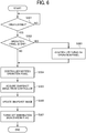
- FIG. 6 is a flowchart illustrating the snapshot image update process according to the present embodiment.
- step S301 the information processing apparatus 1 waits until the timer set in the update execution time determination process expires (No in step S301). When the timer is expired (Yes in step S301), whether the power of the operation panel 110 is off is determined in step S302. If the power is off (Yes in step S302), the power of the operation panel 110 is turned on by the controller 100 in step S303.
- step S304 the package transfer control unit 122 of the controller 100 transmits an update start notification to the operation panel 110, and at the same time, the snapshot image 203 retained in the HDD 112 is transmitted to the operation panel 110 in step S305.
- step S306 the update control unit 133 of the operation panel 110 uses the received snapshot image 203 to update snapshot image and validate the hibernation image.
- the hibernation invalidation flag is set to OFF to enable the hibernation in step S307, and the snapshot image update process ends.
- FIG. 7 is a flowchart illustrating a selection process of a startup mode by the hibernation invalidation flag.
- the process of FIG. 7 is executed by the update control unit 133 of the operation panel 110, for example.
- the device activation is started in step S401, whether the hibernation invalidation flag is on is determined in step S402.
- step S402 Only when the hibernation invalidation flag is off (No in step S402) and the hibernation is valid, the startup using the snapshot image is performed. When the hibernation invalidation flag is on, the startup is performed without using the snapshot image in step S404.
- FIG. 8 is an example of a time-based usage counter based on number of printing.
- FIG. 8 illustrates an example in which the information processing apparatus 1 includes a printing function.
- the time is divided at predetermined intervals (every hour in the example of FIG. 8 ), and the counter value is recorded for each time.
- the counter value is incremented by 1 each time printing is performed at the relevant time.
- the counter value represents usage frequency at each time. In the example of FIG. 8 , printing is performed 10 times at 23:00, 7 times at 24:00, and no printing is performed at 0:00. The printing is most frequently performed at 23:00.
- the timer value is set to the time (for example, 1 o'clock) having the smallest counter value.
- the snapshot image is updated during the time when usage is least frequent, and the load on the information processing apparatus 1 is reduced.
- FIG. 9 is a diagram illustrating an example of a snapshot image update setting screen 300. As illustrated in FIG. 9 , various setting values related to the above-described update process can be selected and input through the snapshot image update setting screen 300 as a user interface displayed on a screen such as a touch panel of the operation panel 110. The input value is stored on the SSD of the operation panel 110, for example.
- a time difference designation input field 301 In the setting screen 300 of FIG. 9 , a time difference designation input field 301, a time designation input field 302, an "automatic" selection button 303, and an “immediate” selection button 304 are displayed.
- the timer value When time is input in the input field 301 for designating the time difference, the timer value is set to the value obtained by adding the designated time to the current time in step S202 of the update execution time determination process in FIG. 5 .
- the timer value When time is input in the time designation input field 302, the timer value is set to the designated time in step S204 of the update execution time determination process of FIG. 5 .
- the "automatic" selection button 303 is selected in step S205 of the update execution time determination process of FIG.
- the timer value is set to the time having the smallest counter value among the time-based usage counters.
- the process proceeds to step S104 in step S103 of FIG. 3 , and the snapshot image update process of the present embodiment is not performed, and the snapshot image is updated at the same time as the firmware update.
- FIG. 10 is a diagram illustrating a conventional update process of the information processing apparatus. As illustrated in FIG. 10 , when the package 200 for update is input to the controller 100 through the SD card 109, for example, the package 200 is decompressed and stored in the storage in the controller 100 in the first stage.
- the CTL system is updated using the CTL system update image 201 (firmware) of the package 200 stored in the storage.
- the operation panel package 204 of the package 200 stored in the storage is transferred to the operation panel 110 through USB or the like and stored in the storage in the operation panel 110.
- the operation panel package 204 is decompressed in the storage of the operation panel 110, and the operation system update image 202 and the snapshot image 203 are expanded.
- the operation system update image 202 is used to update the operation system, and at the same time, the snapshot image 203 is used to update the snapshot.
- the conventional update method has a problem that the update of the snapshot is also performed when the operation panel package is updated, and thus the update is slow.
- the package update and the snapshot update are individually performed.
- FIG. 11 is a diagram illustrating a package update process according to the present embodiment. Since the first and second stages are the same as in FIG. 10 , description thereof is omitted. In the third stage, of the operation panel package 204 of the package 200 stored in the storage of the controller 100, only the operation system update image 202 is transferred to the operation panel 110 through USB, etc. and stored in the storage in the operation panel 110.
- the update time can be shortened by the amount of snapshot update.
- the snapshot image is invalidated, and hibernation is not started until the snapshot illustrated in FIG. 12 is updated.
- FIG. 12 is a diagram illustrating an update process when updating a snapshot image according to the present embodiment.
- the first stage at the timing when the snapshot image can be updated, only the snapshot image 203 of the operation panel package 204 of the package 200 stored in the storage of the controller 100 is transferred to the operation panel 110 through USB or the like and stored in the storage in the operation panel 110.
- the snapshot image is enabled to perform hibernation boot after the next boot.
- the update control unit 133 of the operation panel 110 updates the snapshot image, which is the boot image used for hibernation, at a timing different from the firmware update timing.
- the snapshot image can be updated at an appropriate timing without depending on the firmware update, so the snapshot image is updated efficiently.
- the snapshot image update can be executed after a predetermined time from the firmware update.
- the snapshot image update can be executed at a timing that is definitely different from the firmware update.
- the snapshot image can be updated at the designated time.
- the snapshot image can be updated at a time when the frequency of usage is low.
- the time zone with the least usage frequency can be automatically selected to execute snapshot image update, and the user's effort of setting the update time can be reduced.
- the package transfer control unit 122 of the controller 100 when updating the firmware of the controller 100 in the update package 200 held in the controller 100, transmits the firmware for updating the operation panel 110 (operation system update image 202) to the operation panel 110, and the update snapshot image 203 of the operation panel 110 is transmitted to the operation panel 110 with a shift from the firmware update timing of the controller 100.
- the update control unit 133 of the operation panel 110 executes firmware update of the operation panel 110 when receiving the operation system update image 202 of the operation panel 110 from the package transfer control unit 122, and when the update snapshot image 203 is received from the package transfer control unit 122, the snapshot image of the operation panel 110 is updated.
- the update control unit 133 of the operation panel 110 performs update process by using update data each time the update data is received from the controller 100. It is possible to easily stagger the timing of firmware update and snapshot image update. As a result, a desired update process can be implemented with the present configuration.
- the present disclosure can be implemented in any convenient form, for example using dedicated hardware, or a mixture of dedicated hardware and software.
- the present disclosure may be implemented as computer software implemented by one or more networked processing apparatuses.
- the processing apparatuses can include any suitably programmed apparatuses such as a general purpose computer, personal digital assistant, mobile telephone (such as a Wireless Application Protocol (WAP) or 3G-compliant phone) and so on. Since the present disclosure can be implemented as software, each and every aspect of the present disclosure thus encompasses computer software implementable on a programmable device.
- the computer software can be provided to the programmable device using any conventional carrier medium (carrier means).
- the carrier medium can include a transient carrier medium such as an electrical, optical, microwave, acoustic or radio frequency signal carrying the computer code.
- transient medium is a Transmission Control Protocol/Internet Protocol (TCP/IP) signal carrying computer code over an IP network, such as the internet.
- the carrier medium can also include a storage medium for storing processor readable code such as a floppy disk, hard disk, compact disc read only memory (CD ROM), magnetic tape device or solid state memory device.
- processor readable code such as a floppy disk, hard disk, compact disc read only memory (CD ROM), magnetic tape device or solid state memory device.
- CD ROM compact disc read only memory
- the present disclosure can be implemented in any convenient form, for example using dedicated hardware, or a mixture of dedicated hardware and software.
- the present disclosure may be implemented as computer software implemented by one or more networked processing apparatuses.
- the processing apparatuses can include any suitably programmed apparatuses such as a general purpose computer, personal digital assistant, mobile telephone (such as a Wireless Application Protocol (WAP) or 3G-compliant phone) and so on.
- WAP Wireless Application Protocol
- the present disclosure can be implemented as software, each and every aspect of the present disclosure thus encompasses computer software implementable on a programmable device.
- the computer software can be provided to the programmable device using any conventional carrier medium (carrier means).
- the carrier medium can include a transient carrier medium such as an electrical, optical, microwave, acoustic or radio frequency signal carrying the computer code.
- An example of such a transient medium is a Transmission Control Protocol/Internet Protocol (TCP/IP) signal carrying computer code over an IP network, such as the internet.
- TCP/IP Transmission Control Protocol/Internet Protocol
- the carrier medium can also include a storage medium for storing processor readable code such as a floppy disk, hard disk, compact disc read only memory (CD ROM), magnetic tape device or solid state memory device.
Abstract
Description
- The present disclosure relates to an information processing apparatus, an information processing apparatus update method, and a carrier means.
- A method of updating a boot image (snapshot image) for hibernation when updating system firmware is known.
- A method of shortening update time is disclosed in Japanese Patent No.
2004-242242 - However, in the conventional update method described in the
above Patent Document 1, the update time can be shortened only when the firmware and the snapshot image are matched, and when the firmware and the snapshot image are not matched, the update time of the snapshot image is not shortened. - Embodiments of the present disclosure describe an information processing apparatus, an information processing apparatus update method, and a carrier means. The information processing apparatus (1) executes update of a snapshot image (203) that is a boot image used for hibernation, at a time different from firmware update timing. According to the embodiments of the present disclosure, the snapshot image can be updated efficiently.
- A more complete appreciation of the embodiments and many of the attendant advantages and features thereof can be readily obtained and understood from the following detailed description with reference to the accompanying drawings, wherein:
-
FIG. 1 is a block diagram illustrating a hardware configuration of an information processing apparatus according to embodiments of the present disclosure; -
FIG. 2 is a block diagram illustrating an example of a configuration of a package for updating the information processing apparatus; -
FIG. 3 is a flowchart illustrating an update process of the information processing apparatus according to embodiments of the present disclosure; -
FIG. 4 is a block diagram illustrating a functional configuration of information processing apparatus according to the update process ofFIG. 3 ; -
FIG. 5 is a flowchart illustrating an update execution time determination process; -
FIG. 6 is a flowchart illustrating a snapshot image update process according to embodiments of the present disclosure; -
FIG. 7 is a flowchart illustrating a selection process of a startup mode by a hibernation invalidation flag; -
FIG. 8 is a diagram illustrating an example of a time-based usage counter based on printing; -
FIG. 9 is a diagram illustrating an example of a snapshot image update setting screen; -
FIG. 10 is a diagram illustrating a conventional update process of the information processing apparatus; -
FIG. 11 is a diagram illustrating a package update process according to embodiments of the present disclosure; and -
FIG. 12 is a diagram illustrating an update process when updating a snapshot image according to embodiments of the present disclosure. - The accompanying drawings are intended to depict embodiments of the present disclosure and should not be interpreted to limit the scope thereof. The accompanying drawings are not to be considered as drawn to scale unless explicitly noted. Also, identical or similar reference numerals designate identical or similar components throughout the several views.
- In describing embodiments illustrated in the drawings, specific terminology is employed for the sake of clarity. However, the disclosure of this specification is not intended to be limited to the specific terminology so selected and it is to be understood that each specific element includes all technical equivalents that have a similar function, operate in a similar manner, and achieve a similar result. As used herein, the singular forms "a", "an", and "the" are intended to include the plural forms as well, unless the context clearly indicates otherwise.
- Referring to the drawings, embodiments of the present disclosure is described. In order to facilitate understanding of the description, the same components are denoted by the same reference numerals in the respective drawings as much as possible, and redundant description is omitted.
-
FIG. 1 is a block diagram illustrating a hardware configuration of aninformation processing apparatus 1 according to the present embodiment. - The
information processing apparatus 1 is, for example, a multifunction device called a multifunction peripheral/printer/product (MFP), that is a device having an image processing function such as a facsimile, a scanner, a copier, or a printer, and a communication function. Theinformation processing apparatus 1 is a single device including, for example, a controller (CTL) 100 including a processor (first processor) such as a central processing unit (CPU) 101 in a main body, and anoperation panel 110 including a processor (second processor) different from theCPU 101. - The
controller 100 includes a CPU 101 (System-on-Chip (SoC) or the like) as an arithmetic device. A dynamic random access memory (DRAM) 103 is connected to theCPU 101 as a storage device. Further, thecontroller 100 includes a Universal Serial Bus interface (USB I/F) 106 (USB host function) as an interface to the outside, and theUSB memory 108 is connected through the USB I/F 106. Anoperation panel 110 that receives a user's operation input is connected to theCPU 101 of thecontroller 100, for example, through the USB I/F 106. - An application specific integrated circuit (ASIC) 102 for image processing and various I/F functions is connected to the
CPU 101. A small capacity non-volatile random access memory (NVRAM) 105 is connected to theASIC 102 as a non-volatile memory for managing user data. The NVRAM 105 stores software setting values and the like. - A Secure Digital (SD) card I/F 107 (SD card slot) is also connected to the ASIC 102 as a storage for an optional program. An
SD card 109 is inserted and connected to the SD card I/F 107. Further, a solid state drive (SSD) 104 is connected to the ASIC 102 as a storage for a program for booting the system. Thecontroller 100 may be connected to a hard disk drive (HDD) 112 as a large-capacity external storage device. Anengine 111 is connected to the ASIC 102. - The present embodiment is a method regarding updating of the
operation panel 110. Like thecontroller 100, theoperation panel 110 also includes components such as an SSD, a RAM, and a CPU inside. -
FIG. 2 is a block diagram illustrating an example of a configuration of apackage 200 for updating the information processing apparatus. When updating the firmware of theinformation processing apparatus 1, thepackage 200 as illustrated inFIG. 2 is installed. - As illustrated in
FIG. 2 , thepackage 200 includes a CTL system update image 201 (firmware) of thecontroller 100, an operation system update image 202 (firmware) of theoperation panel 110, and asnapshot image 203 for theoperation panel 110 created from the operationsystem update image 202. Thesnapshot image 203 stores a snapshot image corresponding to the operationsystem update image 202 of theoperation panel 110. - When all the contents of the
package 200 are updated by one update operation, it is necessary to wait until thesnapshot image 203 is updated, since thepackage 200 has the configuration as illustrated inFIG. 2 . In general, thesnapshot image 203 becomes large in proportion to the capacity of the RAM, file size tends to increase, and the update time becomes a bottleneck. - In the present embodiment, update of the
information processing apparatus 1 is performed according to an update process of flowchart illustrated inFIG. 3. FIG. 3 is the flowchart illustrating the update process of theinformation processing apparatus 1 according to the present embodiment. - In step S101, when the
package 200 is acquired from the SD card I/F 107 of thecontroller 100, thepackage 200 is decompressed and expanded to a storage such as theHDD 112 on thecontroller 100. In step S102, the system update process on thecontroller 100 is executed by the CTLsystem update image 201 of the expandedpackage 200. - In step S103, whether immediate update is selected for the
snapshot image 203 in update settings described below is determined. When the immediate update is selected (Yes in step S103), an operation panel package (the operationsystem update image 202 and the snapshot image 203) is transmitted to the SSD of theoperation panel 110 in step S104. In step S105, anupdate control unit 133 of theoperation panel 110 updates the retained snapshot image by using the receivedsnapshot image 203, and in step S106, updates the system of theoperation panel 110 by the operationsystem update image 202. In step S107, the hibernation invalidation flag is set to off, and hibernation is activated. - On the other hand, when the immediate update is not set (No in step S103), only the operation
system update image 202 is transmitted to theoperation panel 110 in step S108, and thesnapshot image 203 is kept in theHDD 112 of thecontroller 100 so as not to increase unnecessary transmission time. When the received image is only the operationsystem update image 202, theupdate control unit 133 of theoperation panel 110 first updates only the system of theoperation panel 110 by the operationsystem update image 202 in step S109. In step S110, by setting the hibernation invalidation flag to ON, the hibernation activation is temporarily invalidated. In step S111, a timer based on an update time determination process described below is set, and the update process ends. - By executing the update process illustrated in
FIG. 3 , when the snapshot image update setting is not set to immediate update, time required for update is reduced since the update time of thesnapshot image 203 is not included. -
FIG. 4 is a block diagram illustrating a functional configuration ofinformation processing apparatus 1 according to the update process ofFIG. 3 . As illustrated inFIG. 4 , thecontroller 100 includes apackage holding unit 121 and a packagetransfer control unit 122, and theoperation panel 110 includes apackage holding unit 131, anupdate setting unit 132, and anupdate control unit 133. - The
package holding unit 121 holds thepackage 200 for update input to thecontroller 100 through the SD card I/F 107 or the like. Thepackage holding unit 121 executes step S101 in the flowchart ofFIG. 3 . - The package
transfer control unit 122 selects data to be transmitted from thepackage 200 stored in thepackage holding unit 121 according to the update settings information stored in theupdate setting unit 132 and transfers the data to theoperation panel 110. In the present embodiment, the packagetransfer control unit 122 transfers the operation panel package (the operationsystem update image 202 and the snapshot image 203) according to the update settings information stored in theupdate setting unit 132. Alternatively, the packagetransfer control unit 122 may transfer only the operationsystem update image 202 or only thesnapshot image 203. The packagetransfer control unit 122 executes steps S103, S104, and S108 in the flowchart ofFIG. 3 . - The
package holding unit 131 stores the update data transferred from thecontroller 100. In the present embodiment, either the operation panel package (the operationsystem update image 202 and the snapshot image 203), only the operationsystem update image 202, or only thesnapshot image 203 is stored. - The
update setting unit 132 receives the update settings of thesnapshot image 203 by the user, and outputs the update settings information to the packagetransfer control unit 122 of thecontroller 100. - The
update control unit 133 controls the update of thesnapshot image 203 of theoperation panel 110 according to the update data stored in thepackage holding unit 131. In the present embodiment, theupdate setting unit 132 updates the firmware as well as the snapshot image when the operation panel package (the operationsystem update image 202 and the snapshot image 203) is stored in thepackage holding unit 131. On the other hand, when only the operationsystem update image 202 or only thesnapshot image 203 is stored in thepackage holding unit 131, only one of the firmware update and the snapshot image update is executed. Theupdate control unit 133 executes steps S105 to S107 and S109 to S111 in the flowchart ofFIG. 3 . - Each function of the
package holding unit 121 and the packagetransfer control unit 122 of thecontroller 100 of theinformation processing apparatus 1 illustrated inFIG. 4 is implemented by reading and writing data in theDRAM 103 and theHDD 112 while operating various hardware under the control of theCPU 101, by reading computer software (update program) on hardware such as theCPU 101 and theDRAM 103 of thecontroller 100. - Further, each function of the
package holding unit 131, theupdate setting unit 132, and theupdate control unit 133 of theoperation panel 110 illustrated inFIG. 4 is implemented by various hardware operated under the control of the CPU, and the reading and writing of data in the RAM and HDD performed by reading computer software (update program) on the hardware such as the CPU and RAM of theoperation panel 110. In the present embodiment, by executing the update program of theinformation processing apparatus 1 on the computer, thecontroller 100 of theinformation processing apparatus 1 functions as thepackage holding unit 121 and the packagetransfer control unit 122 inFIG. 4 , and theoperation panel 110 of theinformation processing apparatus 1 functions as thepackage holding unit 131, theupdate setting unit 132, and theupdate control unit 133 inFIG 4 . -
FIG. 5 is a flowchart illustrating an update execution time determination process. The flowchart ofFIG. 5 is implemented in step S111 ofFIG. 3 . In the update execution time determination process, timer value to be set differs depending on the settings described below. - In step S201, whether time difference designation is selected is determined. When the time difference designation is selected (Yes in step S201), the timer value is set to a value obtained by adding designated time to the current time in step S202.
- When the time difference designation is not selected (No in step S201), whether time designation is selected is determined in step S203. When the time designation is selected (Yes in step S203), the timer value is set to the designated time in step S204. When the time designation is not selected (No in step S203), the timer value is set to the time having the smallest counter value among the time-based usage counters described below in step S205.
- With reference to
FIG. 6 , a description is given of a snapshot image update process when snap update setting is not immediate update in step S103 of the flowchart ofFIG. 3 .FIG. 6 is a flowchart illustrating the snapshot image update process according to the present embodiment. - In step S301, the
information processing apparatus 1 waits until the timer set in the update execution time determination process expires (No in step S301). When the timer is expired (Yes in step S301), whether the power of theoperation panel 110 is off is determined in step S302. If the power is off (Yes in step S302), the power of theoperation panel 110 is turned on by thecontroller 100 in step S303. - In step S304, the package
transfer control unit 122 of thecontroller 100 transmits an update start notification to theoperation panel 110, and at the same time, thesnapshot image 203 retained in theHDD 112 is transmitted to theoperation panel 110 in step S305. - In step S306, the
update control unit 133 of theoperation panel 110 uses the receivedsnapshot image 203 to update snapshot image and validate the hibernation image. - After the update is completed, the hibernation invalidation flag is set to OFF to enable the hibernation in step S307, and the snapshot image update process ends.
-
FIG. 7 is a flowchart illustrating a selection process of a startup mode by the hibernation invalidation flag. The process ofFIG. 7 is executed by theupdate control unit 133 of theoperation panel 110, for example. When the device activation is started in step S401, whether the hibernation invalidation flag is on is determined in step S402. - Only when the hibernation invalidation flag is off (No in step S402) and the hibernation is valid, the startup using the snapshot image is performed. When the hibernation invalidation flag is on, the startup is performed without using the snapshot image in step S404.
- The time-based usage counter used in step S205 of
FIG. 5 is described with reference toFIG. 8. FIG. 8 is an example of a time-based usage counter based on number of printing.FIG. 8 illustrates an example in which theinformation processing apparatus 1 includes a printing function. - As illustrated in
FIG. 8 , the time is divided at predetermined intervals (every hour in the example ofFIG. 8 ), and the counter value is recorded for each time. The counter value is incremented by 1 each time printing is performed at the relevant time. The counter value represents usage frequency at each time. In the example ofFIG. 8 , printing is performed 10 times at 23:00, 7 times at 24:00, and no printing is performed at 0:00. The printing is most frequently performed at 23:00. - Using the time-based usage counter illustrated in
FIG. 8 , in step S205 ofFIG. 5 , the timer value is set to the time (for example, 1 o'clock) having the smallest counter value. As a result, the snapshot image is updated during the time when usage is least frequent, and the load on theinformation processing apparatus 1 is reduced. -
FIG. 9 is a diagram illustrating an example of a snapshot imageupdate setting screen 300. As illustrated inFIG. 9 , various setting values related to the above-described update process can be selected and input through the snapshot imageupdate setting screen 300 as a user interface displayed on a screen such as a touch panel of theoperation panel 110. The input value is stored on the SSD of theoperation panel 110, for example. - In the
setting screen 300 ofFIG. 9 , a time differencedesignation input field 301, a timedesignation input field 302, an "automatic"selection button 303, and an "immediate"selection button 304 are displayed. When time is input in theinput field 301 for designating the time difference, the timer value is set to the value obtained by adding the designated time to the current time in step S202 of the update execution time determination process inFIG. 5 . When time is input in the timedesignation input field 302, the timer value is set to the designated time in step S204 of the update execution time determination process ofFIG. 5 . When the "automatic"selection button 303 is selected in step S205 of the update execution time determination process ofFIG. 5 , the timer value is set to the time having the smallest counter value among the time-based usage counters. When the "immediate"selection button 304 is selected, the process proceeds to step S104 in step S103 ofFIG. 3 , and the snapshot image update process of the present embodiment is not performed, and the snapshot image is updated at the same time as the firmware update. - Effect of the present embodiment is described with reference to
FIGs. 10 to 12 . -
FIG. 10 is a diagram illustrating a conventional update process of the information processing apparatus. As illustrated inFIG. 10 , when thepackage 200 for update is input to thecontroller 100 through theSD card 109, for example, thepackage 200 is decompressed and stored in the storage in thecontroller 100 in the first stage. - In the second stage, the CTL system is updated using the CTL system update image 201 (firmware) of the
package 200 stored in the storage. - In the third stage, the
operation panel package 204 of thepackage 200 stored in the storage is transferred to theoperation panel 110 through USB or the like and stored in the storage in theoperation panel 110. - In the fourth stage, the
operation panel package 204 is decompressed in the storage of theoperation panel 110, and the operationsystem update image 202 and thesnapshot image 203 are expanded. - In the fifth stage, the operation
system update image 202 is used to update the operation system, and at the same time, thesnapshot image 203 is used to update the snapshot. - As described above, the conventional update method has a problem that the update of the snapshot is also performed when the operation panel package is updated, and thus the update is slow.
- On the other hand, in the present embodiment, as illustrated in
FIGs. 11 and12 , the package update and the snapshot update are individually performed. -
FIG. 11 is a diagram illustrating a package update process according to the present embodiment. Since the first and second stages are the same as inFIG. 10 , description thereof is omitted. In the third stage, of theoperation panel package 204 of thepackage 200 stored in the storage of thecontroller 100, only the operationsystem update image 202 is transferred to theoperation panel 110 through USB, etc. and stored in the storage in theoperation panel 110. - In the fourth stage, only the operation system is updated using the operation
system update image 202, and the snapshot update is not performed. Therefore, the update time can be shortened by the amount of snapshot update. - In the fifth step, the snapshot image is invalidated, and hibernation is not started until the snapshot illustrated in
FIG. 12 is updated. -
FIG. 12 is a diagram illustrating an update process when updating a snapshot image according to the present embodiment. In the first stage, at the timing when the snapshot image can be updated, only thesnapshot image 203 of theoperation panel package 204 of thepackage 200 stored in the storage of thecontroller 100 is transferred to theoperation panel 110 through USB or the like and stored in the storage in theoperation panel 110. - In the second stage, only the snapshot is updated using the
snapshot image 203. - In the third stage, the snapshot image is enabled to perform hibernation boot after the next boot.
- As described above, in the
information processing apparatus 1 according to the present embodiment, theupdate control unit 133 of theoperation panel 110 updates the snapshot image, which is the boot image used for hibernation, at a timing different from the firmware update timing. With this configuration, it is not necessary to wait for the snapshot image to be updated when the firmware is updated, so the firmware is updated efficiently. Also, the snapshot image can be updated at an appropriate timing without depending on the firmware update, so the snapshot image is updated efficiently. - Further, in the present embodiment, as described with reference to step S202 of
FIG. 5 and the time differencedesignation input field 301 ofFIG. 9 , the snapshot image update can be executed after a predetermined time from the firmware update. As a result, the snapshot image update can be executed at a timing that is definitely different from the firmware update. - Further, in the present embodiment, as described with reference to step S204 of
FIG. 5 and the timedesignation input field 302 ofFIG. 9 , the snapshot image can be updated at the designated time. As a result, for example, it becomes possible to execute the snapshot image update while surely avoiding the device usage time zone, and the convenience is improved. - In addition, in the present embodiment, as described with reference to step S205 in
FIG. 5 and the "automatic"selection button 303 inFIG. 9 , the snapshot image can be updated at a time when the frequency of usage is low. As a result, even when the usage time of the device is not clearly determined, the time zone with the least usage frequency can be automatically selected to execute snapshot image update, and the user's effort of setting the update time can be reduced. - In the present embodiment, the package
transfer control unit 122 of thecontroller 100, when updating the firmware of thecontroller 100 in theupdate package 200 held in thecontroller 100, transmits the firmware for updating the operation panel 110 (operation system update image 202) to theoperation panel 110, and theupdate snapshot image 203 of theoperation panel 110 is transmitted to theoperation panel 110 with a shift from the firmware update timing of thecontroller 100. Theupdate control unit 133 of theoperation panel 110 executes firmware update of theoperation panel 110 when receiving the operationsystem update image 202 of theoperation panel 110 from the packagetransfer control unit 122, and when theupdate snapshot image 203 is received from the packagetransfer control unit 122, the snapshot image of theoperation panel 110 is updated. In the present embodiment, theupdate control unit 133 of theoperation panel 110 performs update process by using update data each time the update data is received from thecontroller 100. It is possible to easily stagger the timing of firmware update and snapshot image update. As a result, a desired update process can be implemented with the present configuration. - The present embodiment is described above with reference to specific examples. However, the present disclosure is not limited to these specific examples. Those obtained by those skilled in the art who make appropriate design changes to these specific examples are also included in the scope of the present disclosure as long as the modified examples have the features of the present disclosure. The elements provided in each of the specific examples described above and the arrangement, conditions, shapes, and the like of the elements are not limited to those illustrated but can be changed as appropriate. The respective elements included in the above-described specific examples can be appropriately combined as long as there is no technical contradiction.
- The present disclosure can be implemented in any convenient form, for example using dedicated hardware, or a mixture of dedicated hardware and software. The present disclosure may be implemented as computer software implemented by one or more networked processing apparatuses. The processing apparatuses can include any suitably programmed apparatuses such as a general purpose computer, personal digital assistant, mobile telephone (such as a Wireless Application Protocol (WAP) or 3G-compliant phone) and so on. Since the present disclosure can be implemented as software, each and every aspect of the present disclosure thus encompasses computer software implementable on a programmable device. The computer software can be provided to the programmable device using any conventional carrier medium (carrier means). The carrier medium can include a transient carrier medium such as an electrical, optical, microwave, acoustic or radio frequency signal carrying the computer code. An example of such a transient medium is a Transmission Control Protocol/Internet Protocol (TCP/IP) signal carrying computer code over an IP network, such as the internet. The carrier medium can also include a storage medium for storing processor readable code such as a floppy disk, hard disk, compact disc read only memory (CD ROM), magnetic tape device or solid state memory device. The present disclosure can be implemented in any convenient form, for example using dedicated hardware, or a mixture of dedicated hardware and software. The present disclosure may be implemented as computer software implemented by one or more networked processing apparatuses. The processing apparatuses can include any suitably programmed apparatuses such as a general purpose computer, personal digital assistant, mobile telephone (such as a Wireless Application Protocol (WAP) or 3G-compliant phone) and so on. Since the present disclosure can be implemented as software, each and every aspect of the present disclosure thus encompasses computer software implementable on a programmable device. The computer software can be provided to the programmable device using any conventional carrier medium (carrier means). The carrier medium can include a transient carrier medium such as an electrical, optical, microwave, acoustic or radio frequency signal carrying the computer code. An example of such a transient medium is a Transmission Control Protocol/Internet Protocol (TCP/IP) signal carrying computer code over an IP network, such as the internet. The carrier medium can also include a storage medium for storing processor readable code such as a floppy disk, hard disk, compact disc read only memory (CD ROM), magnetic tape device or solid state memory device.
- The above-described embodiments are illustrative and do not limit the present disclosure. Thus, numerous additional modifications and variations are possible in light of the above teachings. For example, elements and/or features of different illustrative embodiments may be combined with each other and/or substituted for each other within the scope of the present disclosure. Any one of the above-described operations may be performed in various other ways, for example, in an order different from the one described above.
Claims (7)
- An information processing apparatus (1) having a start-up function by hibernation, the information processing apparatus (1) comprising
an update control unit (133) for executing update of a snapshot image (203) that is a boot image used for hibernation, at a time different from firmware update timing. - The information processing apparatus (1) of claim 1, wherein
the update control unit (133) updates the snapshot image (203) after a predetermined time has passed from the firmware update timing. - The information processing apparatus (1) of claim 1 or 2, wherein
the update control unit (133) updates the snapshot image (203) at a designated time. - The information processing apparatus (1) of any one of claims 1 to 3, wherein
the update control unit (133) updates the snapshot image (203) at a time when usage frequency is the least. - The information processing apparatus (1) of any one of claims 1 to 4 comprising:a controller (100) including a first processor (101); andan operation panel (110) including a second processor, the second processor implementing the update control unit (133),wherein the controller (100) includes a package transfer control unit (122) that transmits update firmware (202) for the operation panel, obtained from an update package (200) held by the controller (100), to the operation panel (110) when updating firmware for the controller (100); andtransmits a snapshot image (203) for updating the operation panel to the operation panel (110) at a time different from the firmware update timing of the controller (100),wherein the update control unit (133) updates the firmware of the operation panel (110) when receiving the update firmware of the operation panel from the package transfer control unit (122); andupdates the snapshot image (203) of the operation panel (110) when the update snapshot image is received from the package transfer control unit (122).
- A method for updating, performed by an information processing apparatus (1) having a hibernation activation function, the method comprising
updating a snapshot image (203) that is a startup image used for hibernation at a time different from firmware update timing. - A carrier means carrying computer readable code for controlling a computer system to carry out the update method for an information processing apparatus (1) of claim 6.
Applications Claiming Priority (1)
| Application Number | Priority Date | Filing Date | Title |
|---|---|---|---|
| JP2019198951A JP7404780B2 (en) | 2019-10-31 | 2019-10-31 | Information processing device, update method and update program for information processing device |
Publications (2)
| Publication Number | Publication Date |
|---|---|
| EP3816796A1 true EP3816796A1 (en) | 2021-05-05 |
| EP3816796B1 EP3816796B1 (en) | 2022-12-21 |
Family
ID=72744657
Family Applications (1)
| Application Number | Title | Priority Date | Filing Date |
|---|---|---|---|
| EP20199863.0A Active EP3816796B1 (en) | 2019-10-31 | 2020-10-02 | Information processing apparatus, information processing apparatus update method, and carrier means |
Country Status (2)
| Country | Link |
|---|---|
| EP (1) | EP3816796B1 (en) |
| JP (1) | JP7404780B2 (en) |
Citations (3)
| Publication number | Priority date | Publication date | Assignee | Title |
|---|---|---|---|---|
| JP2004242242A (en) | 2003-02-10 | 2004-08-26 | Matsushita Electric Ind Co Ltd | Information reproducing apparatus |
| US20090240932A1 (en) * | 2008-03-18 | 2009-09-24 | Yasuhiro Hattori | Information processing device, and method of starting information processing device |
| EP2728467A1 (en) * | 2012-11-06 | 2014-05-07 | Samsung Electronics Co., Ltd | Method of updating boot image for fast booting and image forming apparatus for performing the same |
Family Cites Families (4)
| Publication number | Priority date | Publication date | Assignee | Title |
|---|---|---|---|---|
| JP2005228200A (en) | 2004-02-16 | 2005-08-25 | Ricoh Co Ltd | Electronic device |
| JP4766332B2 (en) | 2006-12-28 | 2011-09-07 | ソニー株式会社 | Information processing apparatus, activation method, and program |
| JP5943681B2 (en) * | 2012-04-09 | 2016-07-05 | キヤノン株式会社 | Information processing apparatus, firmware update method for information processing apparatus, and program |
| JP6149624B2 (en) | 2013-09-10 | 2017-06-21 | 日本電気株式会社 | Firmware execution apparatus, firmware execution method, computer program, and computer apparatus |
-
2019
- 2019-10-31 JP JP2019198951A patent/JP7404780B2/en active Active
-
2020
- 2020-10-02 EP EP20199863.0A patent/EP3816796B1/en active Active
Patent Citations (3)
| Publication number | Priority date | Publication date | Assignee | Title |
|---|---|---|---|---|
| JP2004242242A (en) | 2003-02-10 | 2004-08-26 | Matsushita Electric Ind Co Ltd | Information reproducing apparatus |
| US20090240932A1 (en) * | 2008-03-18 | 2009-09-24 | Yasuhiro Hattori | Information processing device, and method of starting information processing device |
| EP2728467A1 (en) * | 2012-11-06 | 2014-05-07 | Samsung Electronics Co., Ltd | Method of updating boot image for fast booting and image forming apparatus for performing the same |
Also Published As
| Publication number | Publication date |
|---|---|
| JP2021071972A (en) | 2021-05-06 |
| EP3816796B1 (en) | 2022-12-21 |
| JP7404780B2 (en) | 2023-12-26 |
Similar Documents
| Publication | Publication Date | Title |
|---|---|---|
| US7676658B2 (en) | Data processing apparatus configured to load a program corresponding to each of a plurality of functions into a memory and execute the loaded program, and method for loading programs in the data processing apparatus | |
| US9110760B2 (en) | Image forming apparatus, control method for image forming apparatus, and storage medium | |
| JP4833568B2 (en) | Information processing apparatus, image forming apparatus, activation program, and storage medium | |
| US9673869B2 (en) | Communication apparatus configured to perform non-contact communication with external device | |
| US9348578B2 (en) | Information processing apparatus capable of updating firmware, control method therefor, and storage medium storing control program therefor | |
| US8046756B2 (en) | Multifunction processing apparatus and control method thereof | |
| US10089102B2 (en) | Information processing apparatus, method, and program | |
| JP4946141B2 (en) | Configuration change program and information processing apparatus | |
| EP2357780A2 (en) | Image forming apparatus, information processing method, and recording medium storing information processing program | |
| EP3547109B1 (en) | Installing and uninstalling web applications on an image processing apparatus using a software development kit sdk | |
| US20080231868A1 (en) | Information processing apparatus and driver control method | |
| EP3816796B1 (en) | Information processing apparatus, information processing apparatus update method, and carrier means | |
| US9742945B2 (en) | Image forming apparatus to store activation application specifying information that specifies an application to be activated on the operating system of the operation unit in response to the image forming apparatus entering a given state, image forming system, and image forming method | |
| US10838740B2 (en) | Information processing apparatus and startup method | |
| US10455105B2 (en) | Non-transitory computer-readable medium having instructions, information processing device, and control method | |
| EP1898306A1 (en) | Method and apparatus for variably enabling USB interaction | |
| US8314957B2 (en) | Processing apparatus, method of controlling the same, and storage medium | |
| CN108513169B (en) | Method for downloading starting program from chip, chip and liquid crystal television | |
| EP3591557A1 (en) | Embedded device and virus scan program execution method | |
| JP2021094749A (en) | Image forming device | |
| CN114070942B (en) | Print job transmitting apparatus and computer-readable non-transitory recording medium | |
| US20230010685A1 (en) | Image processing apparatus, image processing method, and storage medium | |
| CN112579119A (en) | Firmware update system, electronic device, and computer-readable non-transitory recording medium | |
| US9639373B2 (en) | Reconfigurable embedded device, method of reconfiguring an embedded device and non-transitory recording medium therefor | |
| JP2024000080A (en) | Image processing device, control method, and program |
Legal Events
| Date | Code | Title | Description |
|---|---|---|---|
| PUAI | Public reference made under article 153(3) epc to a published international application that has entered the european phase |
Free format text: ORIGINAL CODE: 0009012 |
|
| STAA | Information on the status of an ep patent application or granted ep patent |
Free format text: STATUS: REQUEST FOR EXAMINATION WAS MADE |
|
| 17P | Request for examination filed |
Effective date: 20201002 |
|
| AK | Designated contracting states |
Kind code of ref document: A1 Designated state(s): AL AT BE BG CH CY CZ DE DK EE ES FI FR GB GR HR HU IE IS IT LI LT LU LV MC MK MT NL NO PL PT RO RS SE SI SK SM TR |
|
| RIC1 | Information provided on ipc code assigned before grant |
Ipc: G06F 9/4401 20180101ALN20220615BHEP Ipc: G06F 8/654 20180101AFI20220615BHEP |
|
| GRAP | Despatch of communication of intention to grant a patent |
Free format text: ORIGINAL CODE: EPIDOSNIGR1 |
|
| STAA | Information on the status of an ep patent application or granted ep patent |
Free format text: STATUS: GRANT OF PATENT IS INTENDED |
|
| INTG | Intention to grant announced |
Effective date: 20220728 |
|
| GRAS | Grant fee paid |
Free format text: ORIGINAL CODE: EPIDOSNIGR3 |
|
| GRAA | (expected) grant |
Free format text: ORIGINAL CODE: 0009210 |
|
| STAA | Information on the status of an ep patent application or granted ep patent |
Free format text: STATUS: THE PATENT HAS BEEN GRANTED |
|
| AK | Designated contracting states |
Kind code of ref document: B1 Designated state(s): AL AT BE BG CH CY CZ DE DK EE ES FI FR GB GR HR HU IE IS IT LI LT LU LV MC MK MT NL NO PL PT RO RS SE SI SK SM TR |
|
| REG | Reference to a national code |
Ref country code: GB Ref legal event code: FG4D |
|
| REG | Reference to a national code |
Ref country code: CH Ref legal event code: EP |
|
| REG | Reference to a national code |
Ref country code: DE Ref legal event code: R096 Ref document number: 602020007045 Country of ref document: DE |
|
| REG | Reference to a national code |
Ref country code: AT Ref legal event code: REF Ref document number: 1539458 Country of ref document: AT Kind code of ref document: T Effective date: 20230115 |
|
| REG | Reference to a national code |
Ref country code: IE Ref legal event code: FG4D |
|
| REG | Reference to a national code |
Ref country code: NL Ref legal event code: FP |
|
| REG | Reference to a national code |
Ref country code: LT Ref legal event code: MG9D |
|
| PG25 | Lapsed in a contracting state [announced via postgrant information from national office to epo] |
Ref country code: SE Free format text: LAPSE BECAUSE OF FAILURE TO SUBMIT A TRANSLATION OF THE DESCRIPTION OR TO PAY THE FEE WITHIN THE PRESCRIBED TIME-LIMIT Effective date: 20221221 Ref country code: NO Free format text: LAPSE BECAUSE OF FAILURE TO SUBMIT A TRANSLATION OF THE DESCRIPTION OR TO PAY THE FEE WITHIN THE PRESCRIBED TIME-LIMIT Effective date: 20230321 Ref country code: LT Free format text: LAPSE BECAUSE OF FAILURE TO SUBMIT A TRANSLATION OF THE DESCRIPTION OR TO PAY THE FEE WITHIN THE PRESCRIBED TIME-LIMIT Effective date: 20221221 Ref country code: FI Free format text: LAPSE BECAUSE OF FAILURE TO SUBMIT A TRANSLATION OF THE DESCRIPTION OR TO PAY THE FEE WITHIN THE PRESCRIBED TIME-LIMIT Effective date: 20221221 |
|
| REG | Reference to a national code |
Ref country code: AT Ref legal event code: MK05 Ref document number: 1539458 Country of ref document: AT Kind code of ref document: T Effective date: 20221221 |
|
| PG25 | Lapsed in a contracting state [announced via postgrant information from national office to epo] |
Ref country code: RS Free format text: LAPSE BECAUSE OF FAILURE TO SUBMIT A TRANSLATION OF THE DESCRIPTION OR TO PAY THE FEE WITHIN THE PRESCRIBED TIME-LIMIT Effective date: 20221221 Ref country code: LV Free format text: LAPSE BECAUSE OF FAILURE TO SUBMIT A TRANSLATION OF THE DESCRIPTION OR TO PAY THE FEE WITHIN THE PRESCRIBED TIME-LIMIT Effective date: 20221221 Ref country code: HR Free format text: LAPSE BECAUSE OF FAILURE TO SUBMIT A TRANSLATION OF THE DESCRIPTION OR TO PAY THE FEE WITHIN THE PRESCRIBED TIME-LIMIT Effective date: 20221221 Ref country code: GR Free format text: LAPSE BECAUSE OF FAILURE TO SUBMIT A TRANSLATION OF THE DESCRIPTION OR TO PAY THE FEE WITHIN THE PRESCRIBED TIME-LIMIT Effective date: 20230322 |
|
| PG25 | Lapsed in a contracting state [announced via postgrant information from national office to epo] |
Ref country code: SM Free format text: LAPSE BECAUSE OF FAILURE TO SUBMIT A TRANSLATION OF THE DESCRIPTION OR TO PAY THE FEE WITHIN THE PRESCRIBED TIME-LIMIT Effective date: 20221221 Ref country code: RO Free format text: LAPSE BECAUSE OF FAILURE TO SUBMIT A TRANSLATION OF THE DESCRIPTION OR TO PAY THE FEE WITHIN THE PRESCRIBED TIME-LIMIT Effective date: 20221221 Ref country code: PT Free format text: LAPSE BECAUSE OF FAILURE TO SUBMIT A TRANSLATION OF THE DESCRIPTION OR TO PAY THE FEE WITHIN THE PRESCRIBED TIME-LIMIT Effective date: 20230421 Ref country code: ES Free format text: LAPSE BECAUSE OF FAILURE TO SUBMIT A TRANSLATION OF THE DESCRIPTION OR TO PAY THE FEE WITHIN THE PRESCRIBED TIME-LIMIT Effective date: 20221221 Ref country code: EE Free format text: LAPSE BECAUSE OF FAILURE TO SUBMIT A TRANSLATION OF THE DESCRIPTION OR TO PAY THE FEE WITHIN THE PRESCRIBED TIME-LIMIT Effective date: 20221221 Ref country code: CZ Free format text: LAPSE BECAUSE OF FAILURE TO SUBMIT A TRANSLATION OF THE DESCRIPTION OR TO PAY THE FEE WITHIN THE PRESCRIBED TIME-LIMIT Effective date: 20221221 Ref country code: AT Free format text: LAPSE BECAUSE OF FAILURE TO SUBMIT A TRANSLATION OF THE DESCRIPTION OR TO PAY THE FEE WITHIN THE PRESCRIBED TIME-LIMIT Effective date: 20221221 |
|
| P01 | Opt-out of the competence of the unified patent court (upc) registered |
Effective date: 20230714 |
|
| PG25 | Lapsed in a contracting state [announced via postgrant information from national office to epo] |
Ref country code: SK Free format text: LAPSE BECAUSE OF FAILURE TO SUBMIT A TRANSLATION OF THE DESCRIPTION OR TO PAY THE FEE WITHIN THE PRESCRIBED TIME-LIMIT Effective date: 20221221 Ref country code: PL Free format text: LAPSE BECAUSE OF FAILURE TO SUBMIT A TRANSLATION OF THE DESCRIPTION OR TO PAY THE FEE WITHIN THE PRESCRIBED TIME-LIMIT Effective date: 20221221 Ref country code: IS Free format text: LAPSE BECAUSE OF FAILURE TO SUBMIT A TRANSLATION OF THE DESCRIPTION OR TO PAY THE FEE WITHIN THE PRESCRIBED TIME-LIMIT Effective date: 20230421 Ref country code: AL Free format text: LAPSE BECAUSE OF FAILURE TO SUBMIT A TRANSLATION OF THE DESCRIPTION OR TO PAY THE FEE WITHIN THE PRESCRIBED TIME-LIMIT Effective date: 20221221 |
|
| REG | Reference to a national code |
Ref country code: DE Ref legal event code: R097 Ref document number: 602020007045 Country of ref document: DE |
|
| PLBE | No opposition filed within time limit |
Free format text: ORIGINAL CODE: 0009261 |
|
| STAA | Information on the status of an ep patent application or granted ep patent |
Free format text: STATUS: NO OPPOSITION FILED WITHIN TIME LIMIT |
|
| PG25 | Lapsed in a contracting state [announced via postgrant information from national office to epo] |
Ref country code: DK Free format text: LAPSE BECAUSE OF FAILURE TO SUBMIT A TRANSLATION OF THE DESCRIPTION OR TO PAY THE FEE WITHIN THE PRESCRIBED TIME-LIMIT Effective date: 20221221 |
|
| 26N | No opposition filed |
Effective date: 20230922 |
|
| PGFP | Annual fee paid to national office [announced via postgrant information from national office to epo] |
Ref country code: NL Payment date: 20231019 Year of fee payment: 4 |
|
| PG25 | Lapsed in a contracting state [announced via postgrant information from national office to epo] |
Ref country code: SI Free format text: LAPSE BECAUSE OF FAILURE TO SUBMIT A TRANSLATION OF THE DESCRIPTION OR TO PAY THE FEE WITHIN THE PRESCRIBED TIME-LIMIT Effective date: 20221221 |
|
| PGFP | Annual fee paid to national office [announced via postgrant information from national office to epo] |
Ref country code: FR Payment date: 20231026 Year of fee payment: 4 Ref country code: DE Payment date: 20231020 Year of fee payment: 4 |