EP3816640A1 - Système de mesure de rapport charge sur masse pour buse de pulvérisation par atomisation électrostatique et procédé de mesure associé - Google Patents
Système de mesure de rapport charge sur masse pour buse de pulvérisation par atomisation électrostatique et procédé de mesure associé Download PDFInfo
- Publication number
- EP3816640A1 EP3816640A1 EP19920240.9A EP19920240A EP3816640A1 EP 3816640 A1 EP3816640 A1 EP 3816640A1 EP 19920240 A EP19920240 A EP 19920240A EP 3816640 A1 EP3816640 A1 EP 3816640A1
- Authority
- EP
- European Patent Office
- Prior art keywords
- cylinder
- electrostatic atomization
- atomization nozzle
- liquid
- charge
- Prior art date
- Legal status (The legal status is an assumption and is not a legal conclusion. Google has not performed a legal analysis and makes no representation as to the accuracy of the status listed.)
- Granted
Links
Images


Classifications
-
- G—PHYSICS
- G01—MEASURING; TESTING
- G01R—MEASURING ELECTRIC VARIABLES; MEASURING MAGNETIC VARIABLES
- G01R29/00—Arrangements for measuring or indicating electric quantities not covered by groups G01R19/00 - G01R27/00
- G01R29/24—Arrangements for measuring quantities of charge
-
- B—PERFORMING OPERATIONS; TRANSPORTING
- B05—SPRAYING OR ATOMISING IN GENERAL; APPLYING FLUENT MATERIALS TO SURFACES, IN GENERAL
- B05B—SPRAYING APPARATUS; ATOMISING APPARATUS; NOZZLES
- B05B5/00—Electrostatic spraying apparatus; Spraying apparatus with means for charging the spray electrically; Apparatus for spraying liquids or other fluent materials by other electric means
- B05B5/025—Discharge apparatus, e.g. electrostatic spray guns
-
- A—HUMAN NECESSITIES
- A01—AGRICULTURE; FORESTRY; ANIMAL HUSBANDRY; HUNTING; TRAPPING; FISHING
- A01M—CATCHING, TRAPPING OR SCARING OF ANIMALS; APPARATUS FOR THE DESTRUCTION OF NOXIOUS ANIMALS OR NOXIOUS PLANTS
- A01M7/00—Special adaptations or arrangements of liquid-spraying apparatus for purposes covered by this subclass
- A01M7/0089—Regulating or controlling systems
- A01M7/0096—Testing of spray-patterns
-
- G—PHYSICS
- G01—MEASURING; TESTING
- G01M—TESTING STATIC OR DYNAMIC BALANCE OF MACHINES OR STRUCTURES; TESTING OF STRUCTURES OR APPARATUS, NOT OTHERWISE PROVIDED FOR
- G01M99/00—Subject matter not provided for in other groups of this subclass
- G01M99/008—Subject matter not provided for in other groups of this subclass by doing functionality tests
-
- B—PERFORMING OPERATIONS; TRANSPORTING
- B05—SPRAYING OR ATOMISING IN GENERAL; APPLYING FLUENT MATERIALS TO SURFACES, IN GENERAL
- B05B—SPRAYING APPARATUS; ATOMISING APPARATUS; NOZZLES
- B05B14/00—Arrangements for collecting, re-using or eliminating excess spraying material
-
- B—PERFORMING OPERATIONS; TRANSPORTING
- B05—SPRAYING OR ATOMISING IN GENERAL; APPLYING FLUENT MATERIALS TO SURFACES, IN GENERAL
- B05B—SPRAYING APPARATUS; ATOMISING APPARATUS; NOZZLES
- B05B15/00—Details of spraying plant or spraying apparatus not otherwise provided for; Accessories
- B05B15/40—Filters located upstream of the spraying outlets
Definitions
- the present invention relates to a system for measuring a charge-to-mass ratio of an electrostatic atomization nozzle and a measurement method using the same, and in particular, to a system for measuring a charge-to-mass ratio of an electrostatic atomization nozzle and a measurement method using the same, which are capable of measuring in real time and monitoring the charge-to-mass ratio parameter of the electrostatic atomization nozzle, wherein the measurement system is applicable to real-time measurement and monitoring of the charge-to-mass ratio parameter of the electrostatic atomization nozzle in agricultural plant protection spraying, industrial electrostatic spraying, and other fields.
- the electrostatic atomization technology is a liquid atomization spraying technology widely applied in agricultural plant protection spraying, electrostatic spraying, electrostatic atomization spray combustion, industrial electrostatic precipitation, and other fields.
- the electrostatic atomization nozzle developed based on the electrostatic atomization technology features small spray flow, fine particle size, uniform droplets, easy adsorption to the target, good backside adhesion effect, and so on.
- agricultural plant protection spraying machines using the electrostatic atomization nozzles generally have the advantages of pesticide saving, water saving, high working efficiency, and good pest control effects.
- the electrostatic atomization nozzles are widely used in products such as knapsack sprayers, stretcher-mounted sprayers, mist sprayers, and orchard sprayers.
- the charge-to-mass ratio parameter is a key indicator of the product performance of the electrostatic atomization nozzles, and has an important influence on the spraying effect of the electrostatic atomization nozzles.
- a conventional device for measuring the charge-to-mass ratio mainly uses a Faraday cylinder or grid as a droplet collection component to collect charged droplets sprayed by the nozzle, that is, collects the charged droplets sprayed by the electrostatic atomization nozzle within a period of time (the spray time, generally ranging from dozens of seconds to several minutes) through the Faraday cylinder or grid, measures the total mass of the collected droplets by using a weighing instrument such as a balance, and meanwhile, measures the value of the current produced by the charged droplets flowing through the components such as the Faraday cylinder or grid by using an ammeter, and calculates the charge-to-mass ratio parameter of the nozzle through the value of the current I, the total mass of the droplets m, and the spray time t by using the formula (1):
- the conventional measurement device has the following major problems.
- the Chinese patent document with the application number of 201210457633.6 discloses a device for measuring the charge-to-mass ratio in electrostatic spraying.
- the device consists of a liquid collection cylinder, a measuring cylinder, a precision electronic balance, a picoammeter, and a data acquisition and processing system.
- the measurement device collects charged droplets through the liquid collection cylinder.
- the liquid collection cylinder consists of an outer liquid collection cylinder, an inner liquid collection cylinder, and an insulator between the inner and outer cylinders.
- the liquid inside the liquid collection cylinder is delivered to the measuring cylinder through a hose.
- the precision electronic balance is used for weighing the total mass of the droplets in the measuring cylinder.
- the picoammeter is used for current measurement.
- This measurement device is a conventional device for measuring the charge-to-mass ratio.
- the Chinese patent document with the application number of 201310359398.3 discloses an easily disassembled and assembled device for real-time measurement of the charge-to-mass ratio of charged droplets.
- the device consists of a movable base, a bracket, a support plate, a hanger, an ammeter tray, a balance tray, and a Faraday cylinder. It also collects charged droplets by using the Faraday cylinder and measures the total mass of the droplets by using the balance.
- this measurement device can be easily disassembled and moved by means of mechanisms such as the movable base designed in this patent.
- the content of this patent is an improved design of the conventional measurement device.
- the Chinese patent document with the application number of 201310690188.2 discloses an device for measuring the charge-to-mass ratio in boom multi-nozzle electrostatic spraying.
- the device consists of an L-shaped bracket, a vertical moving platform, a horizontal sliding table, a Faraday cylinder, a precision balance, an ammeter, a lifting mechanism, and so on. It collects charged droplets by using the Faraday cylinder and measures the total mass of the droplets by using the precision balance.
- the measurement device of this invention is applicable to the measurement of the charge-to-mass ratio in boom multi-nozzle spraying.
- the content of this patent is also an improved design of the conventional measurement device.
- the Chinese patent document with the application number of 201610007625.X discloses a device for measuring the charge-to-mass ratio of droplets in electrostatic spraying.
- the device mainly consists of a Faraday cylinder, a coulometer, a weight sensor, a water outlet pipeline, a liquid collection barrel, and a computer. It also collects charged droplets by using the Faraday cylinder, delivers the charged droplets in the Faraday cylinder to the liquid collection barrel through the water outlet pipeline, and measures the total mass of the droplets in the liquid collection barrel by using the weight sensor.
- This device is also a conventional device for measuring the charge-to-mass ratio.
- the Chinese patent document with the application number of 201810322387.0 discloses a test stand for the charge-to-mass ratio of droplets in aviation plant protection electrostatic spraying.
- the test stand consists of a mesh charge-to-mass ratio collection box, a water collection tank, an electrostatic spraying system, a picoammeter, a computer, and so on. It mainly collects charged droplets by using the mesh charge-to-mass ratio collection box.
- the mesh charge-to-mass ratio collection box has multiple layers of copper meshes.
- the picoammeter is connected to the copper meshes to measure the current produced by the charged droplets flowing through the copper meshes.
- the water collection tank of the device gathers the collected droplets to facilitate weighing.
- the test stand is also a conventional device for measuring the charge-to-mass ratio.
- the charge-to-mass ratio parameter is a key indicator of the performance of an electrostatic atomization nozzle.
- the conventional device and method for measuring the charge-to-mass ratio have problems such as long measurement time, slow response, and poor accuracy.
- the present invention designs a system for measuring a charge-to-mass ratio of an electrostatic atomization nozzle and a measurement method using the same based on the principle of steady free outflow of a liquid flowing through an orifice of a vessel.
- the system and the method are capable of measuring in real time and monitoring the charge-to-mass ratio parameter of the electrostatic atomization nozzle, and feature high accuracy, rapid response, and the like.
- a system for measuring a charge-to-mass ratio of an electrostatic atomization nozzle includes an electrostatic atomization nozzle, an insulating bracket, an upper cylinder, a water retaining ring, a vortex breaker, a flow regulating plate, a lower cylinder, a lower-cylinder water outlet pipe, an ammeter, a metal conducting wire, a liquid level tube, an ultrasonic level meter, a water storage tank, a water supply pipe, a liquid pump, a branch pipeline, a pressure regulating valve, a throttle valve, a filter, a flowmeter, and a computer.
- the upper cylinder is formed by circumferentially connecting a gradually expanding upper-cylinder end cover and a thin-walled columnar upper-cylinder main body, the lower end of the upper cylinder is an opening, the upper end of the upper cylinder is the upper-cylinder end cover, and an end-cover central hole is provided at the center of the upper-cylinder end cover.
- the lower cylinder is formed by circumferentially welding a thin-walled columnar lower-cylinder main body and a gradually reducing lower-cylinder bottom cover, the upper end of the lower cylinder is an opening, and the lower end of the lower-cylinder bottom cover is connected to the lower-cylinder water outlet pipe.
- the upper cylinder and the lower cylinder are connected through an upper-cylinder flange and a lower-cylinder flange, thereby forming an internal cylindrical space with two open ends between the upper cylinder and the lower cylinder.
- the electrostatic atomization nozzle, the upper cylinder, and the lower cylinder are sequentially connected from top to bottom, and the electrostatic atomization nozzle is mounted in the middle of the end-cover central hole and sprays charged droplets vertically downward.
- the ammeter is connected to the lower-cylinder flange through the metal conducting wire, and is capable of measuring in real time the current produced by the charged droplets sprayed by the electrostatic atomization nozzle into the lower cylinder.
- the charged droplets sprayed by the electrostatic atomization nozzle are gathered in the lower cylinder, and under the influence of its own gravity, the liquid flows to the water storage tank through the lower-cylinder water outlet pipe, while the bottom end of the water storage tank is communicated with the water supply pipe and the liquid pump, enabling the liquid in the water storage tank to be delivered by the liquid pump to an inlet of the electrostatic atomization nozzle and again sprayed into the lower cylinder by the electrostatic atomization nozzle.
- the water supply pipe is communicated with the branch pipeline, and a part of the liquid delivered by the liquid pump flows back to the water storage tank through the branch pipeline.
- the liquid level tube is L-shaped and consists of a horizontal short tube and a vertical long tube which have thin-walled round tubular structures, the horizontal short tube is communicated with the lower cylinder, and the ultrasonic level meter is mounted on the upper end of the vertical long tube and is capable of measuring in real time the liquid level height in the liquid level tube and the lower cylinder.
- the ammeter, the ultrasonic level meter, and the flowmeter are connected to the computer through data cables, and the computer acquires and processes in real time measurement data of the ammeter, the ultrasonic level meter, and the flowmeter, thereby achieving real-time measurement and monitoring of the charge-to-mass ratio parameter of the electrostatic atomization nozzle.
- the upper cylinder is fixed to a top fixing end through the insulating bracket, and the inner diameter of the upper-cylinder main body is equal to the inner diameter Di of the lower-cylinder main body.
- the wall of the upper cylinder is 8-12 millimeters thick.
- the water retaining ring is of a thin-walled columnar structure coaxial with the upper cylinder and is located in the upper cylinder, and the upper end surface of the water retaining ring is connected to the lower surface of the upper-cylinder end cover.
- the inner diameter of the water retaining ring is a half of the inner diameter Di of the lower-cylinder main body, and the water retaining ring is 2-4 millimeters thick.
- end-cover vent holes are provided on the edge of the upper-cylinder end cover, so that the internal cylindrical space formed between the upper cylinder and the lower cylinder is open to the atmosphere, and the end-cover vent holes are uniformly distributed along the circumference of the edge of the upper-cylinder end cover.
- the insulating bracket, the upper cylinder, and the water retaining ring are made of an insulating material, such as rubber, polyethylene, polypropylene, or polyvinyl chloride.
- the vortex breaker and the flow regulating plate are disposed in the lower-cylinder main body, the vortex breaker is of a crossed structure formed by flat steel bars, and the flow regulating plate is of a circular steel plate structure provided with circular flow-through holes.
- the vortex breaker and the flow regulating plate are sequentially and horizontally arranged in the lower-cylinder main body from top to bottom, and the liquid gathered in the lower cylinder passes through the vortex breaker and the flow regulating plate in the process of flowing downward.
- the lower-cylinder flange is welded on the upper end surface of the lower-cylinder main body, the lower-cylinder flange and the upper-cylinder flange are matched and fixedly connected with each other, so that the upper cylinder and the lower cylinder are coaxially and fixedly connected, and a gasket is arranged between the lower-cylinder flange and the upper-cylinder flange to prevent leakage of the liquid.
- the lower cylinder and the lower-cylinder water outlet pipe are made of a metal material such as carbon steel, stainless steel, and aluminum alloys, and the outer surfaces thereof are treated with polymer spraying to improve insulation performance from outside.
- the walls of the lower cylinder and the lower-cylinder water outlet pipe are 5-8 millimeters thick.
- the upper-cylinder main body and the lower-cylinder main body are of thin-walled columnar structures
- the flow regulating plate of a circular steel plate structure is horizontally arranged in the lower-cylinder main body, a certain number of the circular flow-through holes are provided on the surface of the flow regulating plate, and the diameter d 2 of the circular flow-through hole, the number N of the circular flow-through holes, and the inner diameter Di of the lower-cylinder main body satisfy the following relationship: 0.4 ⁇ Nd 2 2 D 1 2 ⁇ 0.6
- the liquid level tube is located on the side surface of the lower cylinder and consists of the horizontal short tube and the vertical long tube welded together, the horizontal short tube is horizontally arranged, and the vertical long tube is vertically arranged.
- a liquid level tube vent hole is provided on the upper end of the vertical long tube, so that the liquid level tube is open to the atmosphere, and meanwhile, the horizontal short tube is communicated with the lower cylinder, thereby forming mutual communication between the liquid level tube, the lower cylinder, and the atmosphere, wherein the center of the liquid level tube vent hole is higher than the end surface of the lower-cylinder flange.
- the ultrasonic level meter is mounted on the upper end of the vertical long tube, the probe of the ultrasonic level meter faces vertically downward, and the ultrasonic level meter is capable of measuring in real time the liquid level height in the liquid level tube and the lower cylinder.
- the liquid level tube is made of a metal material such as carbon steel, stainless steel, and aluminum alloys, and the outer surface thereof is treated with polymer spraying.
- the wall of the liquid level tube is 4-6 millimeters thick and is not thicker than that of the lower cylinder.
- the ammeter is a microammeter or picoammeter, the input end of the ammeter is connected to the outer surface of the lower-cylinder flange through the metal conducting wire, and the output end of the ammeter is connected to a ground terminal.
- the water storage tank is a cylindrical vessel having a closed bottom end and an opening upper end and is located below the lower-cylinder water outlet pipe, the water storage tank is communicated with the inlet of the electrostatic atomization nozzle through the water supply pipe, the liquid pump, the throttle valve, the filter, and the flowmeter, and the flowmeter is located near the inlet of the electrostatic atomization nozzle and acquires in real time the spray flow of the electrostatic atomization nozzle.
- the water supply pipe is arranged between the liquid pump and the throttle valve and is connected to the branch pipeline.
- the pressure regulating valve is disposed on the branch pipeline and is capable of being controlled to adjust the output pressure of the liquid pump and the spray pressure of the electrostatic atomization nozzle.
- the water storage tank is made of a metal material such as carbon steel, stainless steel, and aluminum alloys, and the water supply pipe and the branch pipeline are made of an insulating material, such as rubber, polyethylene, polypropylene, or polyvinyl chloride.
- the measurement system has the following two working modes:
- the first working mode is used for measuring the charge-to-mass ratio parameter of the electrostatic atomization nozzle of an electrostatic sprayer in a working state, and in this case, the electrostatic sprayer is directly connected to the electrostatic atomization nozzle, the electrostatic atomization nozzle is a part of the electrostatic sprayer, and during the spray test, the electrostatic sprayer provides the electrostatic atomization nozzle with the liquid to be sprayed.
- the liquid pump, the pressure regulating valve, and the throttle valve are in a closed state.
- the electrostatic atomization nozzle functions as an independent component to be measured and is not connected to the external electrostatic sprayer, the liquid is driven by the liquid pump to flow in closed circulation in the components such as the electrostatic atomization nozzle, the lower cylinder, the lower-cylinder water outlet pipe, the water storage tank, and the water supply pipe, so that the electrostatic atomization nozzle is continuously supplied with the liquid to be sprayed and the proceeding of the spray test is ensured, and meanwhile, the pressure regulating valve is controlled to adjust the output pressure of the liquid pump and the spray pressure of the electrostatic atomization nozzle, to realize measurement of the charge-to-mass ratio parameter under different spray pressures.
- the liquid pump, the pressure regulating valve, and the throttle valve are in an open state.
- the electrostatic atomization nozzle When the electrostatic atomization nozzle is in the first working mode or the second working mode, the charged droplets sprayed downward by the electrostatic atomization nozzle are gathered in the lower cylinder, and under the influence of its own gravity, the liquid gathered in the lower cylinder flows to the water storage tank through the lower-cylinder water outlet pipe, and the charges carried by the charged droplets flow to the ground through the lower cylinder, the metal conducting wire, and the ammeter; therefore, the current produced by the charged droplets sprayed by the electrostatic atomization nozzle into the lower cylinder can be measured in real time by the ammeter.
- the liquid level in the lower cylinder is low, and the liquid flow from the lower-cylinder water outlet pipe to the water storage tank is smaller than the spray flow of the electrostatic atomization nozzle.
- the liquid level in the lower cylinder gradually increases, and according to the principle of steady free outflow of a liquid flowing through an orifice of a vessel, the liquid flow from the lower-cylinder water outlet pipe to the water storage tank increases accordingly.
- the liquid flow from the lower-cylinder water outlet pipe to the water storage tank is equal to the spray flow of the electrostatic atomization nozzle.
- the liquid level height in the lower cylinder can be measured by using the ultrasonic level meter, and based on the principle of steady free outflow of a liquid flowing through an orifice of a vessel, the spray flow can be calculated indirectly. Meanwhile, the value of the current produced by the charged droplets sprayed by the electrostatic atomization nozzle into the lower cylinder is measured by the ammeter. Based on this, the charge-to-mass ratio parameter of the electrostatic atomization nozzle can be acquired through the spray flow and the current value, thereby achieving real-time measurement and monitoring of the charge-to-mass ratio parameter of the electrostatic atomization nozzle.
- the system for measuring the charge-to-mass ratio of an electrostatic atomization nozzle and the measurement method using the same have the following features:
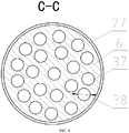
- electrostatic atomization nozzle 2. insulating bracket, 3. upper cylinder, 4. water retaining ring, 5. vortex breaker, 6. flow regulating plate, 7. lower cylinder, 8. lower-cylinder water outlet pipe, 9. ammeter, 10. metal conducting wire, 11. liquid level tube, 12. ultrasonic level meter, 13. water storage tank, 14. water supply pipe, 15. liquid pump, 16. branch pipeline, 17. pressure regulating valve, 18. throttle valve, 19. filter, 20. flowmeter, 21. water supply pipe of an electrostatic sprayer, 22. end-cover central hole, 23. upper-cylinder end cover, 24. end-cover vent hole, 25. upper-cylinder main body, 26. upper-cylinder flange, 27. lower-cylinder flange, 28. lower-cylinder main body, 29.
- lower-cylinder bottom cover 30. inner diameter Di of the lower-cylinder main body, 31. height H of the lower cylinder, 32. inner diameter d 1 of the lower-cylinder water outlet pipe, 33. length Li of the lower-cylinder water outlet pipe, 34. horizontal short tube, 35. vertical long tube, 36. liquid level tube vent hole, 37. circular flow-through hole, 38. diameter d 2 of the circular flow-through hole.
- FIG. 1 to FIG. 4 show the structure of an embodiment of the measurement system.
- the system for measuring the charge-to-mass ratio of an electrostatic atomization nozzle and the measurement method using the same provided by the present invention are described clearly and completely below with reference to the accompanying drawings of the embodiment of the present invention.
- FIG. 1 and FIG. 2 are schematic views of the system for measuring the charge-to-mass ratio of an electrostatic atomization nozzle provided by the embodiment of the present invention.
- the measurement system consists of an electrostatic atomization nozzle 1, an insulating bracket 2, an upper cylinder 3, a water retaining ring 4, a vortex breaker 5, a flow regulating plate 6, a lower cylinder 7, a lower-cylinder water outlet pipe 8, an ammeter 9, a metal conducting wire 10, a liquid level tube 11, an ultrasonic level meter 12, a water storage tank 13, a water supply pipe 14, a liquid pump 15, a branch pipeline 16, a pressure regulating valve 17, a throttle valve 18, a filter 19, a flowmeter 20, and a computer.
- the upper cylinder 3 consists of a gradually expanding upper-cylinder end cover 23 and a thin-walled columnar upper-cylinder main body 25.
- the lower end of the upper cylinder 3 is an opening, and the upper end of the upper cylinder 3 is the upper-cylinder end cover 23.
- An end-cover central hole 22 is provided at the center of the upper-cylinder end cover 23.
- the lower cylinder 7 is formed by circumferentially welding a thin-walled columnar lower-cylinder main body 28 and a gradually reducing lower-cylinder bottom cover 29.
- the upper end of the lower cylinder 7 is an opening.
- the lower end of the lower-cylinder bottom cover 29 is connected to the lower-cylinder water outlet pipe 8.
- the upper cylinder 3 and the lower cylinder 7 are vertically connected through an upper-cylinder flange 26 and a lower-cylinder flange 27, thereby forming an internal cylindrical space with two open ends between the upper cylinder 3 and the lower cylinder 7.
- the electrostatic atomization nozzle 1, the upper cylinder 3, and the lower cylinder 7 are vertically and sequentially connected from top to bottom.
- the electrostatic atomization nozzle 1 is mounted in the middle of the end-cover central hole 22, and sprays charged droplets vertically downward.
- the ammeter 9 is connected to the lower-cylinder flange 27 through the metal conducting wire 10. The charged droplets sprayed by the electrostatic atomization nozzle 1 are gathered in the lower cylinder 7.
- the liquid flows to the water storage tank 13 through the lower-cylinder water outlet pipe 8.
- the bottom end of the water storage tank 13 is communicated with the water supply pipe 14 and the liquid pump 15, enabling the liquid in the water storage tank 13 to be delivered by the liquid pump 15 to an inlet of the electrostatic atomization nozzle 1 and again sprayed into the lower cylinder 7 by the electrostatic atomization nozzle 1.
- the water supply pipe 14 is communicated with the branch pipeline 16.
- a part of the liquid delivered by the liquid pump 15 flows back to the water storage tank 13 through the branch pipeline 16.
- the liquid level tube 11 is L-shaped and consists of a horizontal short tube 34 and a vertical long tube 35 which have thin-walled round tubular structures.
- the horizontal short tube 34 is communicated with the lower cylinder 7.
- the ultrasonic level meter 12 is mounted on the upper end of the vertical long tube 35 and is capable of measuring in real time the liquid level height in the liquid level tube 11 and the lower cylinder 7.
- the ammeter 9, the ultrasonic level meter 12, and the flowmeter 20 are connected to the computer through data cables.
- the computer acquires and processes in real time measurement data of the ammeter 9, the ultrasonic level meter 12, and the flowmeter 20, thereby achieving real-time measurement and monitoring of the charge-to-mass ratio parameter of the electrostatic atomization nozzle 1.
- the insulating bracket 2 is fixedly connected between the upper-cylinder end cover 23 and a top fixing end, and thus the upper cylinder 3 is fixed to the top fixing end through the insulating bracket 2.
- the inner diameter of the upper-cylinder main body 25 is equal to the inner diameter Di of the lower-cylinder main body.
- the inner diameter of the upper-cylinder main body 25 is 0.4 meters, and the wall of the upper cylinder 3 is 8 millimeters thick.
- the water retaining ring 4 is of a thin-walled columnar structure coaxial with the upper cylinder 3, and is located in the upper cylinder 3.
- the upper end surface of the water retaining ring 4 is connected to the lower surface of the upper-cylinder end cover 23.
- the inner diameter of the water retaining ring 4 is 0.2 meters, ensuring that the charged droplets sprayed by the electrostatic atomization nozzle 1 may not directly hit the inner surface of the water retaining ring 4.
- the water retaining ring 4 is 2 millimeters thick.
- Several end-cover vent holes 24 are provided on the edge of the upper-cylinder end cover 23, so that the internal cylindrical space formed between the upper cylinder 3 and the lower cylinder 7 is open to the atmosphere.
- the end-cover vent holes 24 are uniformly distributed along the circumference of the edge of the upper-cylinder end cover 23.
- the inner diameter of the end-cover vent hole 24 is 10 millimeters, and the number of the end-cover vent holes 24 is 12.
- the insulating bracket 2, the upper cylinder 3, and the water retaining ring 4 are made of an insulating material, such as rubber, polyethylene, polypropylene, or polyvinyl chloride.
- the vortex breaker 5 and the flow regulating plate 6 are disposed in the lower-cylinder main body 28.
- the vortex breaker 5 is of a crossed structure formed by flat steel bars.
- the flow regulating plate 6 is of a circular steel plate structure provided with circular flow-through holes 37.
- the vortex breaker 5 and the flow regulating plate 6 are sequentially and horizontally arranged in the lower-cylinder main body 28 from top to bottom.
- the liquid gathered in the lower cylinder 7 passes through the vortex breaker 5 and the flow regulating plate 6 in the process of flowing downward.
- the lower-cylinder flange 27 is welded on the upper end surface of the lower-cylinder main body 28.
- the lower-cylinder flange 27 and the upper-cylinder flange 26 are matched and fixedly connected with each other, so that the upper cylinder 3 and the lower cylinder 7 are fixedly connected.
- a gasket is arranged between the lower-cylinder flange 27 and the upper-cylinder flange 26 to prevent leakage of the liquid.
- the lower cylinder 7 and the lower-cylinder water outlet pipe 8 are made of a metal material such as carbon steel, stainless steel, and aluminum alloys, and the outer surfaces thereof are treated with polymer spraying to improve insulation performance from outside.
- the walls of the vortex breaker 5, the flow regulating plate 6, the lower cylinder 7, and the lower-cylinder water outlet pipe 8 are all 6 millimeters thick.
- the upper-cylinder main body 25 and the lower-cylinder main body 28 are of thin-walled columnar structures.
- the inner diameter D 1 of the lower-cylinder main body is 0.4 meters.
- the lower-cylinder water outlet pipe 8 is of a columnar short pipe structure, the inner diameter d 1 of the lower-cylinder water outlet pipe is 0.0035 meters, and the length Li of the lower-cylinder water outlet pipe is 0.015 meters.
- the flow regulating plate 6 of a circular steel plate structure is horizontally arranged in the lower-cylinder main body 28.
- a certain number of the circular flow-through holes 37 are provided on the surface of the flow regulating plate 6 and are distributed at equal intervals.
- the diameter d 2 of the circular flow-through hole, the number N of the circular flow-through holes, and the inner diameter Di of the lower-cylinder main body satisfy the following relationship: 0.4 ⁇ Nd 2 2 D 1 2 ⁇ 0.6 wherein d 2 , in meters, is the diameter of the circular flow-through hole; N is the number of the circular flow-through holes; and Di, in meters, is the inner diameter of the lower-cylinder main body.
- the inner diameter Di of the lower-cylinder main body is 0.4 meters
- the diameter d 2 of the circular flow-through hole is 60 millimeters
- the number N of the circular flow-through holes is 21, which meet the above design requirement.
- the liquid level tube 11 is located on the side surface of the lower cylinder 7, and consists of the horizontal short tube 34 and the vertical long tube 35 welded together.
- the horizontal short tube 34 is horizontally arranged, and the vertical long tube 35 is vertically arranged.
- the inner diameters of the horizontal short tube 34 and the vertical long tube 35 are 0.1 meter, and the walls thereof are 6 millimeters thick.
- a liquid level tube vent hole 36 is provided on the upper end of the vertical long tube 35, so that the liquid level tube 11 is open to the atmosphere, and meanwhile, the horizontal short tube 34 is communicated with the lower cylinder 7, thereby forming mutual communication between the liquid level tube 11, the lower cylinder 7, and the atmosphere.
- the center of the liquid level tube vent hole 36 is higher than the end surface of the lower-cylinder flange 27.
- the diameter of the liquid level tube vent hole 36 is 50 millimeters.
- the ultrasonic level meter 12 is mounted on the upper end of the vertical long tube 35, and the probe of the ultrasonic level meter 12 faces vertically downward.
- the ultrasonic level meter 12 is capable of measuring in real time the liquid level height in the liquid level tube 11 and the lower cylinder 7.
- the liquid level tube 11 is made of a metal material such as carbon steel, stainless steel, and aluminum alloys, and the outer surface thereof is treated with polymer spraying.
- the ammeter 9 is a microammeter or picoammeter. The input end of the ammeter 9 is connected to the outer surface of the lower-cylinder flange 27 through the metal conducting wire 10, and the output end of the ammeter 9 is connected to a ground terminal.
- the water storage tank 13 is a cylindrical vessel having a closed bottom end and an opening upper end, and is located below the lower-cylinder water outlet pipe 8.
- the water storage tank 13 is communicated with the inlet of the electrostatic atomization nozzle 1 through the water supply pipe 14, the liquid pump 15, the throttle valve 18, the filter 19, and the flowmeter 20.
- the flowmeter 20 is located near the inlet of the electrostatic atomization nozzle 1, and acquires in real time the spray flow of the electrostatic atomization nozzle 1.
- the liquid in the water storage tank 13 is driven by the liquid pump 15 to flow through the water supply pipe 14, the throttle valve 18, the filter 19, the flowmeter 20, and the electrostatic atomization nozzle 1, is then sprayed by the electrostatic atomization nozzle 1 into the lower cylinder 7, and again flows to the water storage tank 13 through the lower-cylinder water outlet pipe 8; therefore, the liquid flows in closed circulation in the measurement system.
- the water supply pipe 14 is arranged between the liquid pump 15 and the throttle valve 18 and is connected to the branch pipeline 16.
- the pressure regulating valve 17 is disposed on the branch pipeline 16 and is capable of being controlled to adjust the output pressure of the liquid pump 15 and the spray pressure of the electrostatic atomization nozzle 1.
- An outlet of the branch pipeline 16 is located above the water storage tank 13, and faces the opening upper end of the water storage tank 13, enabling a part of the liquid to flow back to the water storage tank 13 through the branch pipeline 16 and the pressure regulating valve 17.
- the water storage tank 13 is made of a metal material such as carbon steel, stainless steel, and aluminum alloys.
- the water supply pipe 14 and the branch pipeline 16 are made of an insulating material, such as rubber, polyethylene, polypropylene, or polyvinyl chloride.
- the measurement system has two working modes.
- the first working mode is used for measuring the charge-to-mass ratio parameter of the electrostatic atomization nozzle 1 of an electrostatic sprayer in a working state.
- the electrostatic atomization nozzle 1 is directly connected to the electrostatic sprayer, and the external electrostatic sprayer provides the electrostatic atomization nozzle 1 with the liquid to be sprayed.
- the electrostatic atomization nozzle 1 is a part of the electrostatic sprayer.
- the liquid pump 15, the pressure regulating valve 17, and the throttle valve 18 are in a closed state, the computer only acquires measurement data of the ammeter 9 and the ultrasonic level meter 12, and the liquid does not flow in closed circulation in the measurement system.
- the electrostatic atomization nozzle 1 functions as an independent component to be measured, and is not connected to the external electrostatic sprayer.
- the liquid pump 15 the liquid flows in closed circulation in the components such as the electrostatic atomization nozzle 1, the lower cylinder 7, the lower-cylinder water outlet pipe 8, the water storage tank 13, and the water supply pipe 14, so that the electrostatic atomization nozzle 1 is continuously supplied with the liquid to be sprayed and the proceeding of the spray test is ensured.
- the liquid pump 15, the pressure regulating valve 17, and the throttle valve 18 are in an open state, and the computer acquires measurement data of the ammeter 9, the ultrasonic level meter 12, and the flowmeter 20 at the same time.
- the computer acquires in real time the measurement data of the ammeter and the ultrasonic level meter.
- the specific measurement method includes the following steps.
- the computer acquires in real time data of the current I output by the ammeter 9 according to a sampling period T 1 of the ammeter, and acquires in real time data of the liquid level height h output by the ultrasonic level meter 12 according to a sampling period T 2 of the ultrasonic level meter.
- the sampling duration of the computer is t1 ranging from 30T-50T, wherein T is a larger value of T 1 and T 2 .
- the computer When the coefficients of fluctuation S 1 h1 and S 2 h1 fail to satisfy both the conditions S 1 h1 ⁇ 6% and 97% ⁇ S 2 h1 ⁇ 103%, the computer still outputs I1 and h1 as the real-time current value and the real-time liquid level height of this spray test respectively, and meanwhile, outputs the coefficients of fluctuation S 1 h1 and S 2 h1 synchronously for the reference of testers.
- the computer acquires in real time the measurement data of the ammeter, the ultrasonic level meter, and the flowmeter.
- the specific measurement method includes the following steps.
- the computer acquires in real time data of the current I output by the ammeter 9 according to the sampling period T 1 of the ammeter, acquires in real time data of the liquid level height h output by the ultrasonic level meter 12 according to the sampling period T 2 of the ultrasonic level meter, and acquires in real time data of the spray flow q output by the flowmeter 20 according to a sampling period T 3 of the flowmeter.
- the sampling duration of the computer is t2 ranging from 30T-50T, wherein T is the maximum value of T 1 , T 2 , and T 3 .
- the computer When the coefficients of fluctuation S 1 h2 , S 2 h2 , S 1 q1 , and S 2 q1 fail to satisfy all the conditions S 1 h2 ⁇ 6%, 97% ⁇ S 2 h2 ⁇ 103%, S 1 q1 ⁇ 3%, and 98% ⁇ S 2 q1 ⁇ 102%, the computer still outputs I2 and h2 as the real-time current value and the real-time liquid level height of this spray test respectively, and meanwhile, outputs the coefficients of fluctuation S 1 h2 , S 2 h2 , S 1 q1 , and S 2 q1 synchronously for the reference of testers.
- the computer system calculates the charge-to-mass ratio parameter of the electrostatic atomization nozzle according to the real-time current value and the real-time liquid level height output in the spray test.
Landscapes
- Physics & Mathematics (AREA)
- General Physics & Mathematics (AREA)
- Life Sciences & Earth Sciences (AREA)
- Engineering & Computer Science (AREA)
- Insects & Arthropods (AREA)
- Pest Control & Pesticides (AREA)
- Wood Science & Technology (AREA)
- Zoology (AREA)
- Environmental Sciences (AREA)
- Electrostatic Spraying Apparatus (AREA)
- Other Investigation Or Analysis Of Materials By Electrical Means (AREA)
Applications Claiming Priority (2)
| Application Number | Priority Date | Filing Date | Title |
|---|---|---|---|
| CN201910196052.3A CN109975623B (zh) | 2019-03-15 | 2019-03-15 | 一种静电雾化喷头荷质比测量系统及其测量方法 |
| PCT/CN2019/098340 WO2020186682A1 (fr) | 2019-03-15 | 2019-07-30 | Système de mesure de rapport charge sur masse pour buse de pulvérisation par atomisation électrostatique et procédé de mesure associé |
Publications (3)
| Publication Number | Publication Date |
|---|---|
| EP3816640A1 true EP3816640A1 (fr) | 2021-05-05 |
| EP3816640A4 EP3816640A4 (fr) | 2022-04-06 |
| EP3816640B1 EP3816640B1 (fr) | 2022-10-12 |
Family
ID=67078844
Family Applications (1)
| Application Number | Title | Priority Date | Filing Date |
|---|---|---|---|
| EP19920240.9A Active EP3816640B1 (fr) | 2019-03-15 | 2019-07-30 | Système de mesure de rapport charge sur masse pour buse de pulvérisation par atomisation électrostatique et procédé de mesure associé |
Country Status (4)
| Country | Link |
|---|---|
| US (1) | US11150288B2 (fr) |
| EP (1) | EP3816640B1 (fr) |
| CN (1) | CN109975623B (fr) |
| WO (1) | WO2020186682A1 (fr) |
Families Citing this family (6)
| Publication number | Priority date | Publication date | Assignee | Title |
|---|---|---|---|---|
| CN109975623B (zh) * | 2019-03-15 | 2020-12-18 | 江苏大学 | 一种静电雾化喷头荷质比测量系统及其测量方法 |
| CN110570391A (zh) * | 2019-07-24 | 2019-12-13 | 天津科技大学 | 一种基于Image J的喷雾冷冻涂覆效果的图像分析方法 |
| CN112595539B (zh) * | 2020-12-31 | 2022-10-28 | 黑龙江省农业机械工程科学研究院 | 农用药液高压静电喷雾试验台 |
| CN115524545B (zh) * | 2022-08-30 | 2025-07-29 | 江苏大学 | 一种用于测量雾滴群在空气中电荷量变化的装置 |
| CN115902440B (zh) * | 2022-09-22 | 2026-04-07 | 浙江大学 | 一种流化床中颗粒荷质比的检测方法与系统 |
| CN116858884A (zh) * | 2023-07-06 | 2023-10-10 | 中国石油化工股份有限公司 | 一种评价油中杂质沉降过程静电起电特性的装置及方法 |
Family Cites Families (15)
| Publication number | Priority date | Publication date | Assignee | Title |
|---|---|---|---|---|
| US4264641A (en) * | 1977-03-17 | 1981-04-28 | Phrasor Technology Inc. | Electrohydrodynamic spraying to produce ultrafine particles |
| US4581675A (en) * | 1980-09-02 | 1986-04-08 | Exxon Research And Engineering Co. | Electrostatic atomizing device |
| JPH05345905A (ja) * | 1992-06-12 | 1993-12-27 | Kawasaki Steel Corp | 高圧水アトマイズ噴霧槽液面計測装置 |
| GB0229493D0 (en) * | 2002-12-18 | 2003-01-22 | Battelle Memorial Institute | Aroma dispensing device |
| WO2006043656A1 (fr) * | 2004-10-21 | 2006-04-27 | Hoya Corporation | Appareil et procédé pour déposer de fines particules |
| CN103149461B (zh) | 2012-11-15 | 2015-04-22 | 江苏大学 | 静电喷雾荷质比测量装置 |
| WO2014194272A2 (fr) * | 2013-05-31 | 2014-12-04 | University Of Washington Through Its Center For Commercialization | Interface de spectromètre de masse pour gouttelettes |
| CN103439589B (zh) | 2013-08-19 | 2015-10-28 | 江苏大学 | 一种易拆装荷电雾滴荷质比实时测量装置 |
| CN103675486B (zh) | 2013-12-17 | 2017-01-18 | 江苏大学 | 喷杆式多喷头静电喷雾荷质比测量设备 |
| CN104237974B (zh) * | 2014-09-11 | 2016-06-01 | 河海大学 | 一种虹吸节流翻斗雨量计 |
| CN105676010A (zh) * | 2016-01-07 | 2016-06-15 | 华南农业大学 | 一种测量静电喷雾雾滴荷质比的装置 |
| CN208137933U (zh) * | 2017-11-23 | 2018-11-23 | 王清江 | 一种智能液位监测装置 |
| CN108459213B (zh) * | 2018-04-11 | 2024-01-30 | 黑龙江八一农垦大学 | 航空植保静电喷雾雾滴荷质比检测试验台 |
| TWI675202B (zh) * | 2018-11-30 | 2019-10-21 | 財團法人工業技術研究院 | 流體管路內部靜電量測系統及其方法 |
| CN109975623B (zh) | 2019-03-15 | 2020-12-18 | 江苏大学 | 一种静电雾化喷头荷质比测量系统及其测量方法 |
-
2019
- 2019-03-15 CN CN201910196052.3A patent/CN109975623B/zh active Active
- 2019-07-30 EP EP19920240.9A patent/EP3816640B1/fr active Active
- 2019-07-30 WO PCT/CN2019/098340 patent/WO2020186682A1/fr not_active Ceased
- 2019-07-30 US US17/047,073 patent/US11150288B2/en not_active Expired - Fee Related
Also Published As
| Publication number | Publication date |
|---|---|
| WO2020186682A1 (fr) | 2020-09-24 |
| US11150288B2 (en) | 2021-10-19 |
| CN109975623B (zh) | 2020-12-18 |
| CN109975623A (zh) | 2019-07-05 |
| US20210148961A1 (en) | 2021-05-20 |
| EP3816640B1 (fr) | 2022-10-12 |
| EP3816640A4 (fr) | 2022-04-06 |
Similar Documents
| Publication | Publication Date | Title |
|---|---|---|
| EP3816640B1 (fr) | Système de mesure de rapport charge sur masse pour buse de pulvérisation par atomisation électrostatique et procédé de mesure associé | |
| CN102636344B (zh) | 一种大型喷雾场流量密度分布的一体化测量装置 | |
| US8250907B2 (en) | System and method for determining atomization characteristics of spray liquids | |
| CN105676010A (zh) | 一种测量静电喷雾雾滴荷质比的装置 | |
| CN116026992B (zh) | 矿浆中元素含量的测量装置及测量方法 | |
| CN102052943B (zh) | 测试静电喷雾中雾化空间局部荷质比的装置 | |
| CN101430221A (zh) | 天然气管道内粒子成像装置 | |
| Hu et al. | Motion model for describing the quantity of air in droplets through changing the structure of air induction nozzle | |
| CN108760587A (zh) | 一种用于自吸式文丘里水洗器内液相分布特性测量的装置 | |
| CN107763438A (zh) | 一种雾化加注装置 | |
| CN106940248A (zh) | 测量扁平扇形喷嘴横向喷射不均匀度的装置及方法 | |
| CN107831374A (zh) | 一种液体喷射静电积累量测试装置及方法 | |
| CN219329078U (zh) | 一种验证伯努利定理的流体内部压力分布测量实验装置 | |
| CN207937521U (zh) | 航空植保静电喷雾雾滴荷质比检测试验台 | |
| CN217425156U (zh) | 一种气溶胶冲刷模拟检测装置 | |
| CN222618222U (zh) | 一种燃油喷口的不均匀度测量设备 | |
| CN108459213A (zh) | 航空植保静电喷雾雾滴荷质比检测试验台 | |
| CN209783890U (zh) | 一种用于尿素喷雾性能测试的试验装置 | |
| CN211178609U (zh) | 一种电磁流量计、喷洒系统及无人机 | |
| CN202033426U (zh) | 测试静电喷雾中雾化空间局部荷质比的装置 | |
| CN221883394U (zh) | 一种地连墙渗漏检测装置 | |
| CN106837647A (zh) | 一种喷油器喷孔喷油量测量装置 | |
| Chen et al. | The effects of lateral wind and droplet size on the droplet drift characteristics of fan-shaped nozzles for aerial spraying | |
| CN221325617U (zh) | 一种超声波水表滴水计量测试装置 | |
| CN206772788U (zh) | 一种盐雾试验装置 |
Legal Events
| Date | Code | Title | Description |
|---|---|---|---|
| STAA | Information on the status of an ep patent application or granted ep patent |
Free format text: STATUS: THE INTERNATIONAL PUBLICATION HAS BEEN MADE |
|
| PUAI | Public reference made under article 153(3) epc to a published international application that has entered the european phase |
Free format text: ORIGINAL CODE: 0009012 |
|
| STAA | Information on the status of an ep patent application or granted ep patent |
Free format text: STATUS: REQUEST FOR EXAMINATION WAS MADE |
|
| 17P | Request for examination filed |
Effective date: 20210129 |
|
| AK | Designated contracting states |
Kind code of ref document: A1 Designated state(s): AL AT BE BG CH CY CZ DE DK EE ES FI FR GB GR HR HU IE IS IT LI LT LU LV MC MK MT NL NO PL PT RO RS SE SI SK SM TR |
|
| A4 | Supplementary search report drawn up and despatched |
Effective date: 20220309 |
|
| RIC1 | Information provided on ipc code assigned before grant |
Ipc: B05B 5/00 20060101ALI20220302BHEP Ipc: G01R 29/24 20060101AFI20220302BHEP |
|
| DAV | Request for validation of the european patent (deleted) | ||
| DAX | Request for extension of the european patent (deleted) | ||
| GRAP | Despatch of communication of intention to grant a patent |
Free format text: ORIGINAL CODE: EPIDOSNIGR1 |
|
| STAA | Information on the status of an ep patent application or granted ep patent |
Free format text: STATUS: GRANT OF PATENT IS INTENDED |
|
| INTG | Intention to grant announced |
Effective date: 20220803 |
|
| GRAS | Grant fee paid |
Free format text: ORIGINAL CODE: EPIDOSNIGR3 |
|
| GRAA | (expected) grant |
Free format text: ORIGINAL CODE: 0009210 |
|
| STAA | Information on the status of an ep patent application or granted ep patent |
Free format text: STATUS: THE PATENT HAS BEEN GRANTED |
|
| AK | Designated contracting states |
Kind code of ref document: B1 Designated state(s): AL AT BE BG CH CY CZ DE DK EE ES FI FR GB GR HR HU IE IS IT LI LT LU LV MC MK MT NL NO PL PT RO RS SE SI SK SM TR |
|
| REG | Reference to a national code |
Ref country code: GB Ref legal event code: FG4D |
|
| REG | Reference to a national code |
Ref country code: CH Ref legal event code: EP |
|
| REG | Reference to a national code |
Ref country code: DE Ref legal event code: R096 Ref document number: 602019020684 Country of ref document: DE |
|
| REG | Reference to a national code |
Ref country code: IE Ref legal event code: FG4D |
|
| REG | Reference to a national code |
Ref country code: AT Ref legal event code: REF Ref document number: 1524477 Country of ref document: AT Kind code of ref document: T Effective date: 20221115 |
|
| REG | Reference to a national code |
Ref country code: LT Ref legal event code: MG9D |
|
| REG | Reference to a national code |
Ref country code: NL Ref legal event code: MP Effective date: 20221012 |
|
| REG | Reference to a national code |
Ref country code: AT Ref legal event code: MK05 Ref document number: 1524477 Country of ref document: AT Kind code of ref document: T Effective date: 20221012 |
|
| PG25 | Lapsed in a contracting state [announced via postgrant information from national office to epo] |
Ref country code: NL Free format text: LAPSE BECAUSE OF FAILURE TO SUBMIT A TRANSLATION OF THE DESCRIPTION OR TO PAY THE FEE WITHIN THE PRESCRIBED TIME-LIMIT Effective date: 20221012 |
|
| PG25 | Lapsed in a contracting state [announced via postgrant information from national office to epo] |
Ref country code: SE Free format text: LAPSE BECAUSE OF FAILURE TO SUBMIT A TRANSLATION OF THE DESCRIPTION OR TO PAY THE FEE WITHIN THE PRESCRIBED TIME-LIMIT Effective date: 20221012 Ref country code: PT Free format text: LAPSE BECAUSE OF FAILURE TO SUBMIT A TRANSLATION OF THE DESCRIPTION OR TO PAY THE FEE WITHIN THE PRESCRIBED TIME-LIMIT Effective date: 20230213 Ref country code: NO Free format text: LAPSE BECAUSE OF FAILURE TO SUBMIT A TRANSLATION OF THE DESCRIPTION OR TO PAY THE FEE WITHIN THE PRESCRIBED TIME-LIMIT Effective date: 20230112 Ref country code: LT Free format text: LAPSE BECAUSE OF FAILURE TO SUBMIT A TRANSLATION OF THE DESCRIPTION OR TO PAY THE FEE WITHIN THE PRESCRIBED TIME-LIMIT Effective date: 20221012 Ref country code: FI Free format text: LAPSE BECAUSE OF FAILURE TO SUBMIT A TRANSLATION OF THE DESCRIPTION OR TO PAY THE FEE WITHIN THE PRESCRIBED TIME-LIMIT Effective date: 20221012 Ref country code: ES Free format text: LAPSE BECAUSE OF FAILURE TO SUBMIT A TRANSLATION OF THE DESCRIPTION OR TO PAY THE FEE WITHIN THE PRESCRIBED TIME-LIMIT Effective date: 20221012 Ref country code: AT Free format text: LAPSE BECAUSE OF FAILURE TO SUBMIT A TRANSLATION OF THE DESCRIPTION OR TO PAY THE FEE WITHIN THE PRESCRIBED TIME-LIMIT Effective date: 20221012 |
|
| PG25 | Lapsed in a contracting state [announced via postgrant information from national office to epo] |
Ref country code: RS Free format text: LAPSE BECAUSE OF FAILURE TO SUBMIT A TRANSLATION OF THE DESCRIPTION OR TO PAY THE FEE WITHIN THE PRESCRIBED TIME-LIMIT Effective date: 20221012 Ref country code: PL Free format text: LAPSE BECAUSE OF FAILURE TO SUBMIT A TRANSLATION OF THE DESCRIPTION OR TO PAY THE FEE WITHIN THE PRESCRIBED TIME-LIMIT Effective date: 20221012 Ref country code: LV Free format text: LAPSE BECAUSE OF FAILURE TO SUBMIT A TRANSLATION OF THE DESCRIPTION OR TO PAY THE FEE WITHIN THE PRESCRIBED TIME-LIMIT Effective date: 20221012 Ref country code: IS Free format text: LAPSE BECAUSE OF FAILURE TO SUBMIT A TRANSLATION OF THE DESCRIPTION OR TO PAY THE FEE WITHIN THE PRESCRIBED TIME-LIMIT Effective date: 20230212 Ref country code: HR Free format text: LAPSE BECAUSE OF FAILURE TO SUBMIT A TRANSLATION OF THE DESCRIPTION OR TO PAY THE FEE WITHIN THE PRESCRIBED TIME-LIMIT Effective date: 20221012 Ref country code: GR Free format text: LAPSE BECAUSE OF FAILURE TO SUBMIT A TRANSLATION OF THE DESCRIPTION OR TO PAY THE FEE WITHIN THE PRESCRIBED TIME-LIMIT Effective date: 20230113 |
|
| REG | Reference to a national code |
Ref country code: DE Ref legal event code: R097 Ref document number: 602019020684 Country of ref document: DE |
|
| PG25 | Lapsed in a contracting state [announced via postgrant information from national office to epo] |
Ref country code: SM Free format text: LAPSE BECAUSE OF FAILURE TO SUBMIT A TRANSLATION OF THE DESCRIPTION OR TO PAY THE FEE WITHIN THE PRESCRIBED TIME-LIMIT Effective date: 20221012 Ref country code: RO Free format text: LAPSE BECAUSE OF FAILURE TO SUBMIT A TRANSLATION OF THE DESCRIPTION OR TO PAY THE FEE WITHIN THE PRESCRIBED TIME-LIMIT Effective date: 20221012 Ref country code: EE Free format text: LAPSE BECAUSE OF FAILURE TO SUBMIT A TRANSLATION OF THE DESCRIPTION OR TO PAY THE FEE WITHIN THE PRESCRIBED TIME-LIMIT Effective date: 20221012 Ref country code: DK Free format text: LAPSE BECAUSE OF FAILURE TO SUBMIT A TRANSLATION OF THE DESCRIPTION OR TO PAY THE FEE WITHIN THE PRESCRIBED TIME-LIMIT Effective date: 20221012 Ref country code: CZ Free format text: LAPSE BECAUSE OF FAILURE TO SUBMIT A TRANSLATION OF THE DESCRIPTION OR TO PAY THE FEE WITHIN THE PRESCRIBED TIME-LIMIT Effective date: 20221012 |
|
| PLBE | No opposition filed within time limit |
Free format text: ORIGINAL CODE: 0009261 |
|
| STAA | Information on the status of an ep patent application or granted ep patent |
Free format text: STATUS: NO OPPOSITION FILED WITHIN TIME LIMIT |
|
| PG25 | Lapsed in a contracting state [announced via postgrant information from national office to epo] |
Ref country code: SK Free format text: LAPSE BECAUSE OF FAILURE TO SUBMIT A TRANSLATION OF THE DESCRIPTION OR TO PAY THE FEE WITHIN THE PRESCRIBED TIME-LIMIT Effective date: 20221012 Ref country code: AL Free format text: LAPSE BECAUSE OF FAILURE TO SUBMIT A TRANSLATION OF THE DESCRIPTION OR TO PAY THE FEE WITHIN THE PRESCRIBED TIME-LIMIT Effective date: 20221012 |
|
| 26N | No opposition filed |
Effective date: 20230713 |
|
| PG25 | Lapsed in a contracting state [announced via postgrant information from national office to epo] |
Ref country code: SI Free format text: LAPSE BECAUSE OF FAILURE TO SUBMIT A TRANSLATION OF THE DESCRIPTION OR TO PAY THE FEE WITHIN THE PRESCRIBED TIME-LIMIT Effective date: 20221012 |
|
| REG | Reference to a national code |
Ref country code: DE Ref legal event code: R119 Ref document number: 602019020684 Country of ref document: DE |
|
| PG25 | Lapsed in a contracting state [announced via postgrant information from national office to epo] |
Ref country code: MC Free format text: LAPSE BECAUSE OF FAILURE TO SUBMIT A TRANSLATION OF THE DESCRIPTION OR TO PAY THE FEE WITHIN THE PRESCRIBED TIME-LIMIT Effective date: 20221012 |
|
| PG25 | Lapsed in a contracting state [announced via postgrant information from national office to epo] |
Ref country code: MC Free format text: LAPSE BECAUSE OF FAILURE TO SUBMIT A TRANSLATION OF THE DESCRIPTION OR TO PAY THE FEE WITHIN THE PRESCRIBED TIME-LIMIT Effective date: 20221012 |
|
| REG | Reference to a national code |
Ref country code: CH Ref legal event code: PL |
|
| REG | Reference to a national code |
Ref country code: BE Ref legal event code: MM Effective date: 20230731 |
|
| PG25 | Lapsed in a contracting state [announced via postgrant information from national office to epo] |
Ref country code: LU Free format text: LAPSE BECAUSE OF NON-PAYMENT OF DUE FEES Effective date: 20230730 |
|
| GBPC | Gb: european patent ceased through non-payment of renewal fee |
Effective date: 20230730 |
|
| PG25 | Lapsed in a contracting state [announced via postgrant information from national office to epo] |
Ref country code: LU Free format text: LAPSE BECAUSE OF NON-PAYMENT OF DUE FEES Effective date: 20230730 |
|
| REG | Reference to a national code |
Ref country code: IE Ref legal event code: MM4A |
|
| PG25 | Lapsed in a contracting state [announced via postgrant information from national office to epo] |
Ref country code: DE Free format text: LAPSE BECAUSE OF NON-PAYMENT OF DUE FEES Effective date: 20240201 Ref country code: CH Free format text: LAPSE BECAUSE OF NON-PAYMENT OF DUE FEES Effective date: 20230731 Ref country code: GB Free format text: LAPSE BECAUSE OF NON-PAYMENT OF DUE FEES Effective date: 20230730 |
|
| PG25 | Lapsed in a contracting state [announced via postgrant information from national office to epo] |
Ref country code: IT Free format text: LAPSE BECAUSE OF FAILURE TO SUBMIT A TRANSLATION OF THE DESCRIPTION OR TO PAY THE FEE WITHIN THE PRESCRIBED TIME-LIMIT Effective date: 20221012 Ref country code: FR Free format text: LAPSE BECAUSE OF NON-PAYMENT OF DUE FEES Effective date: 20230731 Ref country code: BE Free format text: LAPSE BECAUSE OF NON-PAYMENT OF DUE FEES Effective date: 20230731 |
|
| PG25 | Lapsed in a contracting state [announced via postgrant information from national office to epo] |
Ref country code: IE Free format text: LAPSE BECAUSE OF NON-PAYMENT OF DUE FEES Effective date: 20230730 |
|
| PG25 | Lapsed in a contracting state [announced via postgrant information from national office to epo] |
Ref country code: IE Free format text: LAPSE BECAUSE OF NON-PAYMENT OF DUE FEES Effective date: 20230730 |
|
| PG25 | Lapsed in a contracting state [announced via postgrant information from national office to epo] |
Ref country code: BG Free format text: LAPSE BECAUSE OF FAILURE TO SUBMIT A TRANSLATION OF THE DESCRIPTION OR TO PAY THE FEE WITHIN THE PRESCRIBED TIME-LIMIT Effective date: 20221012 |
|
| PG25 | Lapsed in a contracting state [announced via postgrant information from national office to epo] |
Ref country code: BG Free format text: LAPSE BECAUSE OF FAILURE TO SUBMIT A TRANSLATION OF THE DESCRIPTION OR TO PAY THE FEE WITHIN THE PRESCRIBED TIME-LIMIT Effective date: 20221012 |
|
| PG25 | Lapsed in a contracting state [announced via postgrant information from national office to epo] |
Ref country code: CY Free format text: LAPSE BECAUSE OF FAILURE TO SUBMIT A TRANSLATION OF THE DESCRIPTION OR TO PAY THE FEE WITHIN THE PRESCRIBED TIME-LIMIT; INVALID AB INITIO Effective date: 20190730 |
|
| PG25 | Lapsed in a contracting state [announced via postgrant information from national office to epo] |
Ref country code: HU Free format text: LAPSE BECAUSE OF FAILURE TO SUBMIT A TRANSLATION OF THE DESCRIPTION OR TO PAY THE FEE WITHIN THE PRESCRIBED TIME-LIMIT; INVALID AB INITIO Effective date: 20190730 |
|
| PG25 | Lapsed in a contracting state [announced via postgrant information from national office to epo] |
Ref country code: TR Free format text: LAPSE BECAUSE OF FAILURE TO SUBMIT A TRANSLATION OF THE DESCRIPTION OR TO PAY THE FEE WITHIN THE PRESCRIBED TIME-LIMIT Effective date: 20221012 |