EP3816416A1 - Method for regenerating a nitrogen oxide trap of an internal combustion engine equipped with a catalyst for selective reduction of nitrogen oxide - Google Patents
Method for regenerating a nitrogen oxide trap of an internal combustion engine equipped with a catalyst for selective reduction of nitrogen oxide Download PDFInfo
- Publication number
- EP3816416A1 EP3816416A1 EP20202982.3A EP20202982A EP3816416A1 EP 3816416 A1 EP3816416 A1 EP 3816416A1 EP 20202982 A EP20202982 A EP 20202982A EP 3816416 A1 EP3816416 A1 EP 3816416A1
- Authority
- EP
- European Patent Office
- Prior art keywords
- trap
- engine
- nitrogen oxides
- regeneration
- mode
- Prior art date
- Legal status (The legal status is an assumption and is not a legal conclusion. Google has not performed a legal analysis and makes no representation as to the accuracy of the status listed.)
- Granted
Links
- MWUXSHHQAYIFBG-UHFFFAOYSA-N Nitric oxide Chemical compound O=[N] MWUXSHHQAYIFBG-UHFFFAOYSA-N 0.000 title claims abstract description 328
- 238000000034 method Methods 0.000 title claims abstract description 46
- 239000003054 catalyst Substances 0.000 title claims abstract description 37
- 230000009467 reduction Effects 0.000 title claims abstract description 26
- 238000002485 combustion reaction Methods 0.000 title claims abstract description 15
- 230000001172 regenerating effect Effects 0.000 title claims abstract description 9
- 238000011069 regeneration method Methods 0.000 claims abstract description 53
- 230000008929 regeneration Effects 0.000 claims abstract description 51
- 239000000446 fuel Substances 0.000 claims abstract description 31
- 239000000203 mixture Substances 0.000 claims abstract description 24
- 238000011144 upstream manufacturing Methods 0.000 claims abstract description 24
- 238000003795 desorption Methods 0.000 claims abstract description 9
- 239000007789 gas Substances 0.000 claims description 23
- 230000008569 process Effects 0.000 claims description 17
- 238000010438 heat treatment Methods 0.000 claims description 8
- 239000003638 chemical reducing agent Substances 0.000 claims description 6
- 238000002347 injection Methods 0.000 claims description 6
- 239000007924 injection Substances 0.000 claims description 6
- 230000003111 delayed effect Effects 0.000 claims description 4
- 238000005485 electric heating Methods 0.000 claims description 2
- 230000000593 degrading effect Effects 0.000 claims 1
- 238000006722 reduction reaction Methods 0.000 description 18
- IJGRMHOSHXDMSA-UHFFFAOYSA-N Atomic nitrogen Chemical compound N#N IJGRMHOSHXDMSA-UHFFFAOYSA-N 0.000 description 9
- XSQUKJJJFZCRTK-UHFFFAOYSA-N Urea Chemical compound NC(N)=O XSQUKJJJFZCRTK-UHFFFAOYSA-N 0.000 description 6
- 239000004202 carbamide Substances 0.000 description 6
- 239000000567 combustion gas Substances 0.000 description 4
- 238000005259 measurement Methods 0.000 description 4
- 239000010705 motor oil Substances 0.000 description 4
- 238000006243 chemical reaction Methods 0.000 description 3
- 230000006835 compression Effects 0.000 description 3
- 238000007906 compression Methods 0.000 description 3
- 239000012895 dilution Substances 0.000 description 3
- 238000010790 dilution Methods 0.000 description 3
- 239000003921 oil Substances 0.000 description 3
- 238000010926 purge Methods 0.000 description 3
- 238000012360 testing method Methods 0.000 description 3
- 230000008901 benefit Effects 0.000 description 2
- 230000000694 effects Effects 0.000 description 2
- 229910052757 nitrogen Inorganic materials 0.000 description 2
- 230000003647 oxidation Effects 0.000 description 2
- 238000007254 oxidation reaction Methods 0.000 description 2
- 238000004064 recycling Methods 0.000 description 2
- 230000009471 action Effects 0.000 description 1
- QVGXLLKOCUKJST-UHFFFAOYSA-N atomic oxygen Chemical compound [O] QVGXLLKOCUKJST-UHFFFAOYSA-N 0.000 description 1
- 238000012550 audit Methods 0.000 description 1
- 230000003416 augmentation Effects 0.000 description 1
- 230000015556 catabolic process Effects 0.000 description 1
- 238000010531 catalytic reduction reaction Methods 0.000 description 1
- 230000007423 decrease Effects 0.000 description 1
- 238000006731 degradation reaction Methods 0.000 description 1
- 230000007613 environmental effect Effects 0.000 description 1
- 230000001747 exhibiting effect Effects 0.000 description 1
- 229930195733 hydrocarbon Natural products 0.000 description 1
- 150000002430 hydrocarbons Chemical class 0.000 description 1
- 238000012804 iterative process Methods 0.000 description 1
- 239000006193 liquid solution Substances 0.000 description 1
- 230000001050 lubricating effect Effects 0.000 description 1
- 238000004519 manufacturing process Methods 0.000 description 1
- 239000001301 oxygen Substances 0.000 description 1
- 229910052760 oxygen Inorganic materials 0.000 description 1
- 238000012805 post-processing Methods 0.000 description 1
- 230000002035 prolonged effect Effects 0.000 description 1
- 239000004071 soot Substances 0.000 description 1
- 238000003860 storage Methods 0.000 description 1
- 238000012795 verification Methods 0.000 description 1
- XLYOFNOQVPJJNP-UHFFFAOYSA-N water Substances O XLYOFNOQVPJJNP-UHFFFAOYSA-N 0.000 description 1
Images

Classifications
-
- F—MECHANICAL ENGINEERING; LIGHTING; HEATING; WEAPONS; BLASTING
- F01—MACHINES OR ENGINES IN GENERAL; ENGINE PLANTS IN GENERAL; STEAM ENGINES
- F01N—GAS-FLOW SILENCERS OR EXHAUST APPARATUS FOR MACHINES OR ENGINES IN GENERAL; GAS-FLOW SILENCERS OR EXHAUST APPARATUS FOR INTERNAL COMBUSTION ENGINES
- F01N3/00—Exhaust or silencing apparatus having means for purifying, rendering innocuous, or otherwise treating exhaust
- F01N3/08—Exhaust or silencing apparatus having means for purifying, rendering innocuous, or otherwise treating exhaust for rendering innocuous
- F01N3/0807—Exhaust or silencing apparatus having means for purifying, rendering innocuous, or otherwise treating exhaust for rendering innocuous by using absorbents or adsorbents
- F01N3/0871—Regulation of absorbents or adsorbents, e.g. purging
- F01N3/0885—Regeneration of deteriorated absorbents or adsorbents, e.g. desulfurization of NOx traps
-
- F—MECHANICAL ENGINEERING; LIGHTING; HEATING; WEAPONS; BLASTING
- F01—MACHINES OR ENGINES IN GENERAL; ENGINE PLANTS IN GENERAL; STEAM ENGINES
- F01N—GAS-FLOW SILENCERS OR EXHAUST APPARATUS FOR MACHINES OR ENGINES IN GENERAL; GAS-FLOW SILENCERS OR EXHAUST APPARATUS FOR INTERNAL COMBUSTION ENGINES
- F01N3/00—Exhaust or silencing apparatus having means for purifying, rendering innocuous, or otherwise treating exhaust
- F01N3/08—Exhaust or silencing apparatus having means for purifying, rendering innocuous, or otherwise treating exhaust for rendering innocuous
- F01N3/0807—Exhaust or silencing apparatus having means for purifying, rendering innocuous, or otherwise treating exhaust for rendering innocuous by using absorbents or adsorbents
- F01N3/0814—Exhaust or silencing apparatus having means for purifying, rendering innocuous, or otherwise treating exhaust for rendering innocuous by using absorbents or adsorbents combined with catalytic converters, e.g. NOx absorption/storage reduction catalysts
-
- F—MECHANICAL ENGINEERING; LIGHTING; HEATING; WEAPONS; BLASTING
- F01—MACHINES OR ENGINES IN GENERAL; ENGINE PLANTS IN GENERAL; STEAM ENGINES
- F01N—GAS-FLOW SILENCERS OR EXHAUST APPARATUS FOR MACHINES OR ENGINES IN GENERAL; GAS-FLOW SILENCERS OR EXHAUST APPARATUS FOR INTERNAL COMBUSTION ENGINES
- F01N3/00—Exhaust or silencing apparatus having means for purifying, rendering innocuous, or otherwise treating exhaust
- F01N3/08—Exhaust or silencing apparatus having means for purifying, rendering innocuous, or otherwise treating exhaust for rendering innocuous
- F01N3/0807—Exhaust or silencing apparatus having means for purifying, rendering innocuous, or otherwise treating exhaust for rendering innocuous by using absorbents or adsorbents
- F01N3/0828—Exhaust or silencing apparatus having means for purifying, rendering innocuous, or otherwise treating exhaust for rendering innocuous by using absorbents or adsorbents characterised by the absorbed or adsorbed substances
- F01N3/0842—Nitrogen oxides
-
- F—MECHANICAL ENGINEERING; LIGHTING; HEATING; WEAPONS; BLASTING
- F01—MACHINES OR ENGINES IN GENERAL; ENGINE PLANTS IN GENERAL; STEAM ENGINES
- F01N—GAS-FLOW SILENCERS OR EXHAUST APPARATUS FOR MACHINES OR ENGINES IN GENERAL; GAS-FLOW SILENCERS OR EXHAUST APPARATUS FOR INTERNAL COMBUSTION ENGINES
- F01N3/00—Exhaust or silencing apparatus having means for purifying, rendering innocuous, or otherwise treating exhaust
- F01N3/08—Exhaust or silencing apparatus having means for purifying, rendering innocuous, or otherwise treating exhaust for rendering innocuous
- F01N3/10—Exhaust or silencing apparatus having means for purifying, rendering innocuous, or otherwise treating exhaust for rendering innocuous by thermal or catalytic conversion of noxious components of exhaust
- F01N3/18—Exhaust or silencing apparatus having means for purifying, rendering innocuous, or otherwise treating exhaust for rendering innocuous by thermal or catalytic conversion of noxious components of exhaust characterised by methods of operation; Control
- F01N3/20—Exhaust or silencing apparatus having means for purifying, rendering innocuous, or otherwise treating exhaust for rendering innocuous by thermal or catalytic conversion of noxious components of exhaust characterised by methods of operation; Control specially adapted for catalytic conversion ; Methods of operation or control of catalytic converters
- F01N3/2066—Selective catalytic reduction [SCR]
-
- F—MECHANICAL ENGINEERING; LIGHTING; HEATING; WEAPONS; BLASTING
- F01—MACHINES OR ENGINES IN GENERAL; ENGINE PLANTS IN GENERAL; STEAM ENGINES
- F01N—GAS-FLOW SILENCERS OR EXHAUST APPARATUS FOR MACHINES OR ENGINES IN GENERAL; GAS-FLOW SILENCERS OR EXHAUST APPARATUS FOR INTERNAL COMBUSTION ENGINES
- F01N9/00—Electrical control of exhaust gas treating apparatus
-
- F—MECHANICAL ENGINEERING; LIGHTING; HEATING; WEAPONS; BLASTING
- F01—MACHINES OR ENGINES IN GENERAL; ENGINE PLANTS IN GENERAL; STEAM ENGINES
- F01N—GAS-FLOW SILENCERS OR EXHAUST APPARATUS FOR MACHINES OR ENGINES IN GENERAL; GAS-FLOW SILENCERS OR EXHAUST APPARATUS FOR INTERNAL COMBUSTION ENGINES
- F01N2430/00—Influencing exhaust purification, e.g. starting of catalytic reaction, filter regeneration, or the like, by controlling engine operating characteristics
- F01N2430/06—Influencing exhaust purification, e.g. starting of catalytic reaction, filter regeneration, or the like, by controlling engine operating characteristics by varying fuel-air ratio, e.g. by enriching fuel-air mixture
-
- F—MECHANICAL ENGINEERING; LIGHTING; HEATING; WEAPONS; BLASTING
- F01—MACHINES OR ENGINES IN GENERAL; ENGINE PLANTS IN GENERAL; STEAM ENGINES
- F01N—GAS-FLOW SILENCERS OR EXHAUST APPARATUS FOR MACHINES OR ENGINES IN GENERAL; GAS-FLOW SILENCERS OR EXHAUST APPARATUS FOR INTERNAL COMBUSTION ENGINES
- F01N2550/00—Monitoring or diagnosing the deterioration of exhaust systems
- F01N2550/03—Monitoring or diagnosing the deterioration of exhaust systems of sorbing activity of adsorbents or absorbents
-
- F—MECHANICAL ENGINEERING; LIGHTING; HEATING; WEAPONS; BLASTING
- F01—MACHINES OR ENGINES IN GENERAL; ENGINE PLANTS IN GENERAL; STEAM ENGINES
- F01N—GAS-FLOW SILENCERS OR EXHAUST APPARATUS FOR MACHINES OR ENGINES IN GENERAL; GAS-FLOW SILENCERS OR EXHAUST APPARATUS FOR INTERNAL COMBUSTION ENGINES
- F01N2570/00—Exhaust treating apparatus eliminating, absorbing or adsorbing specific elements or compounds
- F01N2570/14—Nitrogen oxides
-
- F—MECHANICAL ENGINEERING; LIGHTING; HEATING; WEAPONS; BLASTING
- F01—MACHINES OR ENGINES IN GENERAL; ENGINE PLANTS IN GENERAL; STEAM ENGINES
- F01N—GAS-FLOW SILENCERS OR EXHAUST APPARATUS FOR MACHINES OR ENGINES IN GENERAL; GAS-FLOW SILENCERS OR EXHAUST APPARATUS FOR INTERNAL COMBUSTION ENGINES
- F01N2610/00—Adding substances to exhaust gases
- F01N2610/03—Adding substances to exhaust gases the substance being hydrocarbons, e.g. engine fuel
-
- F—MECHANICAL ENGINEERING; LIGHTING; HEATING; WEAPONS; BLASTING
- F01—MACHINES OR ENGINES IN GENERAL; ENGINE PLANTS IN GENERAL; STEAM ENGINES
- F01N—GAS-FLOW SILENCERS OR EXHAUST APPARATUS FOR MACHINES OR ENGINES IN GENERAL; GAS-FLOW SILENCERS OR EXHAUST APPARATUS FOR INTERNAL COMBUSTION ENGINES
- F01N2900/00—Details of electrical control or of the monitoring of the exhaust gas treating apparatus
- F01N2900/06—Parameters used for exhaust control or diagnosing
- F01N2900/0601—Parameters used for exhaust control or diagnosing being estimated
-
- F—MECHANICAL ENGINEERING; LIGHTING; HEATING; WEAPONS; BLASTING
- F01—MACHINES OR ENGINES IN GENERAL; ENGINE PLANTS IN GENERAL; STEAM ENGINES
- F01N—GAS-FLOW SILENCERS OR EXHAUST APPARATUS FOR MACHINES OR ENGINES IN GENERAL; GAS-FLOW SILENCERS OR EXHAUST APPARATUS FOR INTERNAL COMBUSTION ENGINES
- F01N2900/00—Details of electrical control or of the monitoring of the exhaust gas treating apparatus
- F01N2900/06—Parameters used for exhaust control or diagnosing
- F01N2900/08—Parameters used for exhaust control or diagnosing said parameters being related to the engine
-
- F—MECHANICAL ENGINEERING; LIGHTING; HEATING; WEAPONS; BLASTING
- F01—MACHINES OR ENGINES IN GENERAL; ENGINE PLANTS IN GENERAL; STEAM ENGINES
- F01N—GAS-FLOW SILENCERS OR EXHAUST APPARATUS FOR MACHINES OR ENGINES IN GENERAL; GAS-FLOW SILENCERS OR EXHAUST APPARATUS FOR INTERNAL COMBUSTION ENGINES
- F01N2900/00—Details of electrical control or of the monitoring of the exhaust gas treating apparatus
- F01N2900/06—Parameters used for exhaust control or diagnosing
- F01N2900/16—Parameters used for exhaust control or diagnosing said parameters being related to the exhaust apparatus, e.g. particulate filter or catalyst
- F01N2900/1614—NOx amount trapped in catalyst
-
- F—MECHANICAL ENGINEERING; LIGHTING; HEATING; WEAPONS; BLASTING
- F01—MACHINES OR ENGINES IN GENERAL; ENGINE PLANTS IN GENERAL; STEAM ENGINES
- F01N—GAS-FLOW SILENCERS OR EXHAUST APPARATUS FOR MACHINES OR ENGINES IN GENERAL; GAS-FLOW SILENCERS OR EXHAUST APPARATUS FOR INTERNAL COMBUSTION ENGINES
- F01N2900/00—Details of electrical control or of the monitoring of the exhaust gas treating apparatus
- F01N2900/06—Parameters used for exhaust control or diagnosing
- F01N2900/16—Parameters used for exhaust control or diagnosing said parameters being related to the exhaust apparatus, e.g. particulate filter or catalyst
- F01N2900/1621—Catalyst conversion efficiency
-
- Y—GENERAL TAGGING OF NEW TECHNOLOGICAL DEVELOPMENTS; GENERAL TAGGING OF CROSS-SECTIONAL TECHNOLOGIES SPANNING OVER SEVERAL SECTIONS OF THE IPC; TECHNICAL SUBJECTS COVERED BY FORMER USPC CROSS-REFERENCE ART COLLECTIONS [XRACs] AND DIGESTS
- Y02—TECHNOLOGIES OR APPLICATIONS FOR MITIGATION OR ADAPTATION AGAINST CLIMATE CHANGE
- Y02T—CLIMATE CHANGE MITIGATION TECHNOLOGIES RELATED TO TRANSPORTATION
- Y02T10/00—Road transport of goods or passengers
- Y02T10/10—Internal combustion engine [ICE] based vehicles
- Y02T10/12—Improving ICE efficiencies
Landscapes
- Engineering & Computer Science (AREA)
- Chemical & Material Sciences (AREA)
- Combustion & Propulsion (AREA)
- Mechanical Engineering (AREA)
- General Engineering & Computer Science (AREA)
- Chemical Kinetics & Catalysis (AREA)
- Health & Medical Sciences (AREA)
- Toxicology (AREA)
- Exhaust Gas After Treatment (AREA)
Abstract
L'invention propose un procédé de régénération d'un piège à oxydes d'azote monté dans le circuit d'échappement d'un moteur à combustion interne de véhicule automobile, le circuit comprenant aussi un catalyseur de réductions élective des oxydes d'azote en aval du piège.Selon l'invention, le procédé comprend un premier mode de régénération classique par réduction des oxydes d'azote, dans lequel le moteur est réglé en mélange riche, et un deuxième mode de régénération par désorption des oxydes d'azote, dans lequel la température du piège est augmentée fortement et rapidement, et du carburant du moteur est amené en amont du piège. Le moteur est réglé avec une richesse augmentée par rapport à son fonctionnement habituel, mais néanmoins en mélange pauvre.Quand la masse d'oxydes d'azote dans le piège atteint un seuil de régénération, on utilise le deuxième mode quand le catalyseur de réduction sélective des oxydes d'azote est suffisamment efficace. Les oxydes d'azote désorbés sont ainsi réduits par ledit catalyseur de réduction sélective des oxydes d'azote.The invention proposes a method for regenerating a nitrogen oxide trap mounted in the exhaust circuit of an internal combustion engine of a motor vehicle, the circuit also comprising a catalyst for elective reductions of nitrogen oxides in downstream of the trap. According to the invention, the method comprises a first mode of conventional regeneration by reduction of nitrogen oxides, in which the engine is set to a rich mixture, and a second mode of regeneration by desorption of nitrogen oxides, wherein the temperature of the trap is increased sharply and rapidly, and engine fuel is supplied upstream of the trap. The engine is adjusted with an increased richness compared to its usual operation, but nevertheless in lean mixture.When the mass of nitrogen oxides in the trap reaches a regeneration threshold, the second mode is used when the selective reduction catalyst nitrogen oxides is sufficiently effective. The desorbed nitrogen oxides are thus reduced by said catalyst for the selective reduction of nitrogen oxides.
Description
La présente invention concerne un procédé de régénération d'un piège à oxydes d'azote de moteur à combustion interne équipé par ailleurs d'un catalyseur de réduction sélective des oxydes d'azote. Elle trouve une application particulièrement avantageuse dans les moteurs du type à allumage par compression (diesel) des véhicules automobiles.The present invention relates to a process for regenerating a nitrogen oxides trap of an internal combustion engine which is also equipped with a catalyst for the selective reduction of nitrogen oxides. It finds a particularly advantageous application in engines of the compression ignition (diesel) type of motor vehicles.
L'invention concerne également un dispositif de motorisation pour la mise en œuvre du procédé de régénération selon l'invention.The invention also relates to a motorization device for implementing the regeneration method according to the invention.
Les moteurs à combustion interne modernes, en particulier les moteurs du type à allumage par compression (diesel) des véhicules automobiles qui sont soumis à des normes anti-pollution de plus en plus sévères, sont équipés de divers systèmes de post-traitement des molécules polluantes émises dans les gaz de combustion desdits moteurs, afin de limiter les rejets d'espèces nocives dans l'atmosphère extérieure.Modern internal combustion engines, in particular engines of the compression ignition (diesel) type of motor vehicles which are subject to increasingly stringent anti-pollution standards, are equipped with various systems for post-treatment of polluting molecules. emitted in the combustion gases of said engines, in order to limit the discharges of harmful species into the outside atmosphere.
Les moteurs diesel, qui fonctionnent habituellement en mélange pauvre, émettent notamment de grandes quantités d'oxydes d'azote (NOx) dans leurs gaz de combustion. Pour limiter les rejets de ces NOx dans l'atmosphère extérieure, les moteurs diesel sont souvent équipés d'un piège à oxydes d'azote (dit aussi « NOx trap » selon la terminologie anglaise), qui est monté dans le circuit d'échappement de ces moteurs.Diesel engines, which usually run on a lean mixture, notably emit large amounts of nitrogen oxides (NOx) in their combustion gases. To limit the emissions of these NOx into the outside atmosphere, diesel engines are often equipped with a nitrogen oxide trap (also called "NOx trap" according to English terminology), which is mounted in the exhaust circuit. of these engines.
De manière connue en soi, un piège à oxydes d'azote fonctionne de manière séquentielle. Pendant le fonctionnement habituel du moteur en mélange pauvre, le piège stocke au moins en partie les molécules de NOx émises dans les gaz de combustion du moteur. On désigne par l'expression « efficacité du piège », la proportion de la quantité de NOx émise par le moteur à la sortie du moteur, et entrant dans le piège, qui y est effectivement stockée, plus précisément adsorbée, le reste ce cette quantité entrante étant directement évacué à la sortie du piège.In a manner known per se, a nitrogen oxide trap operates sequentially. During normal lean-burn engine operation, the trap stores at least part of the NOx molecules emitted in the combustion gases of the engine. engine. The expression “trap efficiency” denotes the proportion of the quantity of NOx emitted by the engine at the outlet of the engine, and entering the trap, which is actually stored there, more precisely adsorbed, the rest of this quantity. incoming being directly evacuated at the exit of the trap.
A mesure que le piège se remplit, c'est-à-dire que la masse d'oxydes d'azotes adsorbée dans le piège augmente, l'efficacité du piège diminue, de sorte qu'il rejette de plus en plus de NOx émis par le moteur. Il convient alors de faire diminuer la masse de NOx stockée dans le piège pour restaurer l'efficacité de ce dernier. De manière fréquentielle, par exemple quand la masse de NOx stockée atteint un seuil, on procède un basculement du fonctionnement du moteur dans un autre mode de fonctionnement, dit de régénération, qui a pour effet de vider le piège et de ramener la masse de NOx stockée à zéro ou au moins à une valeur plus faible où l'efficacité est restaurée partiellement.As the trap fills up, i.e. the mass of nitrogen oxides adsorbed in the trap increases, the efficiency of the trap decreases, so that it releases more and more NOx emitted by the engine. It is then advisable to reduce the mass of NOx stored in the trap in order to restore the latter's efficiency. Frequently, for example when the mass of stored NOx reaches a threshold, the operation of the engine is switched to another operating mode, called regeneration, which has the effect of emptying the trap and reducing the mass of NOx. stored at zero or at least at a lower value where efficiency is partially restored.
Pour cela, il est connu de provoquer un basculement du réglage du moteur en mélange riche, c'est-à-dire avec une proportion du mélange air-carburant introduit dans le moteur qui est strictement supérieure à la proportion stœchiométrique, typiquement à une richesse sensiblement égale à 1,05. L'apport, à l'entrée du piège à oxydes d'azote, de carburant non brûlé dans les chambres de combustion du moteur a pour effet de provoquer une réduction du stock de NOx en molécules inoffensives (diazote N2 et eau H2O).For this, it is known to cause the adjustment of the engine to be switched to a rich mixture, that is to say with a proportion of the air-fuel mixture introduced into the engine which is strictly greater than the stoichiometric proportion, typically at richness. substantially equal to 1.05. Adding unburned fuel to the combustion chambers of the engine at the inlet of the nitrogen oxides trap has the effect of reducing the stock of NOx in harmless molecules (nitrogen N 2 and water H 2 O ).
Le basculement du mode de fonctionnement du moteur en mélange riche peut par exemple s'effectuer sans modifier la quantité d'air admise dans le moteur, en injectant une quantité supplémentaire de carburant dans chaque cylindre du moteur à un instant du cycle de combustion qui est suffisamment retardé par rapport au point mort haut de combustion du cylindre pour que cette quantité de carburant ne participe pas à la combustion et qu'elle soit évacuée à l'échappement du moteur. On parle de post-injection tardive du carburant.The switching of the operating mode of the engine in rich mixture can for example be carried out without modifying the quantity of air admitted into the engine, by injecting an additional quantity of fuel into each cylinder of the engine at a moment of the combustion cycle which is sufficiently delayed with respect to the top dead center of combustion of the cylinder so that this quantity of fuel does not participate in the combustion and that it is discharged to the exhaust of the engine. We are talking about late post-injection of fuel.
Cependant, la régénération d'un piège à oxydes d'azote par apport de réducteurs sous forme de carburant imbrûlé pose généralement plusieurs problèmes. Elle entraîne une hausse importante de la consommation de carburant du moteur ; car le moteur fonctionne en mélange riche. D'autre part, comme une proportion du carburant post-injecté tardivement dans les cylindres passe à travers les segments des pistons, elle a tendance à se mélanger à l'huile du moteur et à provoquer une dilution de cette huile par le carburant, ce qui dégrade ses propriétés lubrifiantes. Il devient nécessaire d'augmenter la fréquence des vidanges pour préserver la fiabilité du moteur.However, the regeneration of a nitrogen oxide trap by supplying reducing agents in the form of unburnt fuel generally poses several problems. It causes a significant increase in engine fuel consumption; because the engine works in rich mixture. On the other hand, since a proportion of the late post-injected fuel in the cylinders passes through the piston rings, it tends to mix with the engine oil and cause this oil to be diluted by the fuel, which in turn tends to mix with the engine oil. which degrades its lubricating properties. It becomes necessary to increase the frequency of oil changes to preserve the reliability of the engine.
En outre, la régénération d'un piège à oxydes d'azote par réduction des NOx par le carburant ne peut être mise en œuvre que lorsqu'un certain nombre de conditions de fonctionnement du moteur et du véhicule sont remplies, notamment, de manière non limitative, lorsque le régime et la charge du moteur sont compris dans des plages de régime et de charge prédéterminées et que la variation du régime et la variation de la charge sont comprises dans des plages de variation prédéterminées. Ces conditions correspondent globalement à des conditions de fonctionnement relativement stabilisées du moteur à mi-régime et à mi-charge. En dehors de ces conditions, la régénération est impossible physiquement, ou bien elle doit être interdite pour des raisons de fiabilité.In addition, the regeneration of a nitrogen oxides trap by reduction of NOx by the fuel can only be implemented when a certain number of operating conditions of the engine and of the vehicle are met, in particular, in an unsuccessful manner. limitative, when the engine speed and load are within predetermined speed and load ranges and when the speed variation and the load variation are within predetermined variation ranges. These conditions generally correspond to relatively stabilized engine operating conditions at half speed and half load. Outside of these conditions, regeneration is physically impossible, or it must be prohibited for reliability reasons.
On connaît de l'état de la technique plusieurs procédés de régénération qui visent à résoudre ces problèmes. Par exemple, la
De même, la
On connaît encore de la
Par l'expression « efficacité de la régénération », on entend l'efficacité de la réaction qui se produit à l'intérieur du piège lors de la régénération, en d'autres termes le rendement de la réaction chimique de réduction des molécules de NOx par les hydrocarbures imbrûlés HC. Plus le rendement est faible, plus la quantité de carburant additionnelle à consommer dans le piège pendant la régénération est importante, et plus la régénération est longue.By the expression “regeneration efficiency” is meant the efficiency of the reaction which takes place inside the trap during regeneration, in other words the efficiency of the chemical reaction of reduction of the NOx molecules. by unburnt HC hydrocarbons. The lower the efficiency, the greater the amount of additional fuel to be consumed in the trap during regeneration, and the longer the regeneration takes.
L'efficacité de la régénération étant faible en dessous d'un seuil de température d'environ 300°C, le procédé décrit par cette publication permet, en augmentant la température du piège, d'améliorer l'efficacité des régénérations et de limiter la surconsommation de carburant et la dilution de l'huile du moteur. Cependant, les régénérations se font toujours en mélange riche, ce qui limite le gain obtenu, et leur occurrence reste limitée par la nécessité de réunir une pluralité de conditions de fonctionnement (régime, charge, etc.), ce qui ne supprime pas le risque d'être incapable de vider à temps un piège inefficace car plein de NOx. Les améliorations apportées par ce procédé sont encore insuffisantes.Since the efficiency of the regeneration is low below a temperature threshold of around 300 ° C., the method described by this publication makes it possible, by increasing the temperature of the trap, to improve the efficiency of the regenerations and to limit the overconsumption of fuel and dilution of engine oil. However, the regenerations are always carried out in a rich mixture, which limits the gain obtained, and their occurrence remains limited by the need to combine a plurality of operating conditions (speed, load, etc.), which does not eliminate the risk. to be unable to empty an ineffective trap in time because it is full of NOx. The improvements made by this process are still insufficient.
La présente invention vise à remédier aux défauts des procédés connus de régénération des pièges à oxydes d'azote connus, dans le cas où le moteur dispose en outre, à l'échappement, d'un catalyseur de réduction sélective des oxydes d'azote monté à l'aval du piège.The present invention aims to remedy the shortcomings of the known processes for regenerating known nitrogen oxides traps, in the case where the engine also has, at the exhaust, a catalyst for the selective reduction of nitrogen oxides mounted. downstream of the trap.
Un tel cas de figure est en fait fréquent sur les moteurs diesel modernes. En effet, il est connu que l'efficacité des pièges à oxydes d'azote est limitée. Ils ne permettent généralement de filtrer que 50 à 60% des oxydes d'azote du moteur, ce qui peut s'avérer insuffisant compte tenu de la sévérité des normes. L'utilisation d'un catalyseur de réduction sélective des oxydes d'azote permet, à lui seul ou en combinaison avec un piège à oxydes d'azote, d'obtenir une efficacité de traitement des NOx supérieure à 90%. On conserve généralement un piège à oxydes d'azote en combinaison avec un catalyseur de réduction sélective des oxydes d'azote pour pallier le manque d'efficacité à froid de ce dernier, typiquement en dessous de 180°C.Such a scenario is in fact common in modern diesel engines. Indeed, it is known that the effectiveness of nitrogen oxide traps is limited. They generally only filter 50 to 60% of the nitrogen oxides in the engine, which may be insufficient given the severity of the standards. The use of a catalyst for the selective reduction of nitrogen oxides makes it possible, by itself or in combination with a nitrogen oxides trap, to obtain an NOx treatment efficiency greater than 90%. A nitrogen oxides trap is generally kept in combination with a catalyst for the selective reduction of nitrogen oxides to overcome the lack of efficiency of the latter when cold, typically below 180 ° C.
Le procédé selon l'invention propose un procédé de régénération d'un piège à oxydes d'azote monté dans le circuit d'échappement d'un moteur à combustion interne de véhicule automobile, ledit circuit d'échappement comprenant en outre un catalyseur de réduction sélective des oxydes d'azote à l'aval dudit piège, ledit procédé comprenant :
- une étape de calcul d'une valeur de la masse d'oxydes d'azote stockée dans le piège ;
- une étape de comparaison de ladite valeur de masse avec un seuil ; et,
- lorsque ladite masse est supérieure ou égale audit seuil, une étape de régénération du piège, dans laquelle on élimine des oxydes d'azote du piège par un apport de carburant du moteur en amont du piège, ladite régénération pouvant être réalisée selon au moins un premier mode de fonctionnement du moteur en mélange riche dans lequel les oxydes d'azote sont réduits.
- a step of calculating a value of the mass of nitrogen oxides stored in the trap;
- a step of comparing said mass value with a threshold; and,
- when said mass is greater than or equal to said threshold, a step for regenerating the trap, in which nitrogen oxides are removed from the trap by supplying fuel from the engine upstream of the trap, said regeneration being able to be carried out according to at least a first mode of operation of the engine in rich mixture in which nitrogen oxides are reduced.
La principale caractéristique du procédé selon l'invention est qu'il comprend en outre, lorsque ladite masse d'oxydes d'azote est supérieure ou égale audit seuil :
- une étape dans laquelle on vérifie si les conditions de réalisation de ladite régénération dans ledit premier mode de régénération sont remplies ;
- une étape dans laquelle on vérifie si le catalyseur de réduction sélective des oxydes d'azote présente au moins une efficacité de réduction minimale prédéterminée ;
- lorsque le premier mode est possible et que l'efficacité du catalyseur est insuffisante, une étape de régénération du piège dans ledit premier mode ;
- lorsque l'efficacité du catalyseur est suffisante, une étape de régénération du piège par désorption des oxydes d'azote, dans un deuxième mode de fonctionnement du moteur en mélange pauvre, ledit deuxième mode comprenant une augmentation forte et rapide de la température du piège et un apport de carburant du moteur en amont du piège.
- a step in which it is checked whether the conditions for carrying out said regeneration in said first regeneration mode are met;
- a step in which it is checked whether the catalyst for the selective reduction of nitrogen oxides has at least a predetermined minimum reduction efficiency;
- when the first mode is possible and the efficiency of the catalyst is insufficient, a step of regenerating the trap in said first mode;
- when the efficiency of the catalyst is sufficient, a stage of regeneration of the trap by desorption of nitrogen oxides, in a second mode of operation of the engine in lean mixture, said second mode comprising a strong and rapid increase in the temperature of the trap and an engine fuel supply upstream of the trap.
D'autres caractéristiques et avantages de l'invention apparaîtront à la lecture de la description qui suit d'un mode de réalisation non limitatif de l'invention, à l'appui des figures annexées, dans lesquelles :
- [
Fig. 1 ] est une vue schématique d'un dispositif de motorisation apte à la mise en œuvre du procédé selon l'invention. - [
Fig. 2 ] est un logigramme des étapes d'un mode de réalisation du procédé selon l'invention.
- [
Fig. 1 ] is a schematic view of a motorization device suitable for implementing the method according to the invention. - [
Fig. 2 ] is a flowchart of the steps of an embodiment of the method according to the invention.
Dans la description qui va suivre, des chiffres de référence identiques désignent des pièces identiques ou ayant des fonctions similaires.In the description which follows, identical reference numerals denote identical parts or having similar functions.
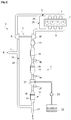
Sur la
Le moteur 1 est associé à un circuit d'admission d'air 2 et à un circuit d'échappement 3. L'air frais prélevé dans l'atmosphère extérieure pénètre dans le circuit d'admission 2 dans le sens de la flèche E, dans un tuyau d'entrée d'air 4. Il peut traverser des composants non représentés sur la figure tels qu'un filtre à air. A l'admission, le moteur 1 comporte un compresseur 5 d'un turbocompresseur 6 de suralimentation. L'air traverse le compresseur 5 puis un collecteur d'admission 7, ou répartiteur 7, du moteur. Une vanne 8 de réglage du débit des gaz admis dans le moteur peut être montée entre le compresseur 5 et le répartiteur 7, ainsi que d'autres composants non représentés, comme par exemple un refroidisseur d'air de suralimentation.The
Les gaz de combustion du moteur sont évacués dans un collecteur d'échappement 9 du moteur, puis ils traversent la turbine 10 du turbocompresseur 6. La turbine peut être du type à géométrie fixe et associée à un circuit de décharge à l'échappement (non représenté) ou du type à géométrie variable, pour le réglage de l'énergie de détente prélevée par la turbine sur les gaz d'échappement.The combustion gases from the engine are discharged into an exhaust manifold 9 of the engine, then they pass through the
Sur l'exemple de la
Ici, le piège à oxydes d'azote 13 est associé à un capteur d'oxydes d'azote amont 18 et à un capteur d'oxydes d'azote aval 19, aptes à mesurer respectivement une valeur de concentration d'oxydes d'azote en amont [NOx]in et en aval [NOx]out du piège. En variante, il est possible que la concentration d'oxydes d'azote amont soit déterminée par un modèle cartographié en fonction du point de fonctionnement du moteur.Here, the nitrogen oxides trap 13 is associated with an upstream
Les mesures de concentration d'oxydes d'azote amont [NOx]in et aval [NOx]out permettent, en association avec la mesure du débit des gaz d'échappement Qech par le débitmètre 11, de déterminer la masse d'oxydes d'azote MNOx stockée dans le piège 13, comme il sera détaillé plus loin. Bien entendu, d'autres variantes sont possibles : Par exemple, il est possible que la concentration d'oxydes d'azote amont [NOx]in soit déterminée par un modèle cartographié en fonction du point de fonctionnement du moteur. Il est aussi possible que le débit des gaz d'échappement soit déterminé par d'autres moyens que le débitmètre 11. Notamment il peut être prévu un débitmètre à l'admission du moteur, apte à mesurer le débit des gaz d'admission Qadm. Le débit des gaz d'échappement est alors déterminé comme la somme dudit débit des gaz d'admission et du débit de carburant Qcarb admis dans le moteur.The measurements of the concentration of nitrogen oxides upstream [NOx] in and downstream [NOx] out make it possible, in association with the measurement of the flow rate of the exhaust gases Qech by the
Sur l'exemple de la
Le catalyseur SCR 16 du troisième dispositif de post-traitement 14 est alimenté en réducteurs à base d'urée (Adblue®) par l'intermédiaire d'un injecteur d'urée qui injecte l'urée dans un mélangeur 21 implanté dans le circuit d'échappement 3 en amont du troisième dispositif de post-traitement 14. Les réducteurs proviennent généralement d'une solution liquide qui est stockée dans un réservoir 22 et qui est acheminée vers l'injecteur d'urée grâce à une pompe 23.The
Pour la mise en œuvre du procédé selon l'invention, le troisième dispositif de post-traitement 14 est associé à des moyens de mesure d'une valeur représentative de la température du catalyseur SCR 16 et/ou de l'injecteur d'urée. Dans l'exemple de la
On notera aussi que d'autres arrangements de dispositifs de post-traitement sont possibles sans nuire à la généralité de l'invention. Par exemple, il est possible que le catalyseur d'oxydation 12 et le piège à oxydes d'azote 13 soient réunis dans un seul dispositif de post-traitement combiné. Il est aussi possible que le filtre à particules 15 et le catalyseur SCR 16 soient des dispositifs de post-traitement séparés.It will also be noted that other arrangements of post-processing devices are possible without harming the generality of the invention. For example, it is possible that the
En outre, le circuit d'échappement comporte ici un circuit de recirculation partielle 25 à haute pression des gaz d'échappement à l'admission du moteur, dit aussi circuit EGR HP (acronyme anglais pour : Exhaust Gas Recycling - High Pressure). Ce circuit prend naissance en un point du circuit d'échappement situé en amont de la turbine 10 et son autre extrémité débouche en un point du circuit d'admission situé en aval du compresseur 5. Il comporte une vanne de réglage 26 du débit des gaz EGR HP recyclés.In addition, the exhaust circuit here comprises a
Le circuit d'échappement comporte en outre un circuit de recirculation partielle 27 à basse pression des gaz d'échappement à l'admission du moteur, dit aussi circuit EGR LP (acronyme anglais pour : Exhaust Gas Recycling - Low Pressure). Ce circuit prend naissance en un point du circuit d'échappement situé en aval de la turbine 10, plus précisément ici après la sortie des différents dispositifs de post-traitement 12,13,14, et son autre extrémité débouche en un point du circuit d'admission situé en amont du compresseur 5. Il comporte une vanne de réglage 28 du débit des gaz EGR LP recyclés. Il peut aussi comporter d'autres composants non représentés, comme par exemple un filtre, un refroidisseur, etc.The exhaust circuit further comprises a
Le fonctionnement du moteur est placé sous la supervision d'un calculateur électronique (non représenté), qui détermine un certain nombre de paramètres de fonctionnement du moteur à partir d'une pluralité de capteurs et qui pilote une pluralité d'actionneurs du moteur.The operation of the engine is placed under the supervision of an electronic computer (not shown), which determines a certain number of operating parameters of the engine from a plurality of sensors and which controls a plurality of actuators of the engine.
Sur la
Par exemple, la température est élevée presque instantanément au-dessus d'une valeur de l'ordre de 600 à 650°C, et la richesse est portée à une valeur voisine de 0,9 , qui est supérieure à la richesse de fonctionnement habituelle d'un moteur diesel (par exemple entre 0,3 et 0,6) sur le point de fonctionnement considéré, mais qui est inférieure à 1, est qui reste donc un mode de fonctionnement en mélange pauvre. On notera que ces conditions de température et de richesse correspondent à celles d'une purge classique de filtre à particules par combustion des suies. Par conséquent, la régénération d'un piège à oxydes d'azote par désorption des NOx adsorbés dans des conditions antérieures de température moins élevée, permet en même temps de purger un filtre à particules présent dans le circuit d'échappement du moteur, ce qui permet d'éviter des purges spécifiques dudit filtre, et ainsi d'économiser globalement du carburant. En outre, comme la richesse du mélange utilisé est plus pauvre que dans le cas d'une régénération du piège par réduction des NOx, la consommation de carburant est moindre. Un avantage supplémentaire est qu'un tel procédé de désorption peut se dérouler sans que les conditions de fonctionnement qui sont habituellement nécessaires à la régénération du piège par réduction des NOx en mélange riche, et qui sont assez contraignantes, soient réunies.For example, the temperature is raised almost instantaneously above a value of the order of 600 to 650 ° C, and the richness is brought to a value close to 0.9, which is greater than the usual operating richness. of a diesel engine (for example between 0.3 and 0.6) on the operating point considered, but which is less than 1, is therefore a lean-mixture operating mode. It will be noted that these temperature and richness conditions correspond to those of a conventional purging of a particulate filter by combustion of soot. Consequently, the regeneration of a nitrogen oxides trap by desorption of the adsorbed NOx under previous conditions of lower temperature, at the same time makes it possible to purge a particulate filter present in the engine exhaust circuit, which makes it possible to avoid specific purges of said filter, and thus to save fuel overall. In addition, as the richness of the mixture used is leaner than in the case of regeneration of the trap by reducing NOx, fuel consumption is lower. An additional advantage is that such a desorption process can take place without the operating conditions which are usually necessary for the regeneration of the trap by reduction of NOx in a rich mixture, and which are quite restrictive, being met.
Toutefois, l'inconvénient de ce mode de régénération par désorption est que les NOx sont relargués dans le circuit d'échappement du moteur sans être traités. Selon le procédé, la présence d'un catalyseur de réduction sélective des oxydes d'azote, monté à l'aval du piège offre le moyen de réduire ces NOx relargués pour éviter qu'ils ne soient rejetés dans l'atmosphère extérieure, dès lors que ledit catalyseur de réduction sélective des oxydes d'azote est efficace.However, the drawback of this method of regeneration by desorption is that the NOx is released into the engine exhaust circuit without being treated. According to the process, the presence of a catalyst for the selective reduction of nitrogen oxides, mounted downstream of the trap, offers the means of reducing these released NOx to prevent them from being released into the outside atmosphere, therefore. that said catalyst for the selective reduction of nitrogen oxides is effective.
La
Le procédé se poursuit par une étape 300 de calcul de la masse d'oxydes d'azote stockée MNOx dans le piège 13. Dans un mode de réalisation, la masse d'oxydes d'azote à l'instant courant t peut se calculer en ajoutant à la valeur calculée à l'instant précédent du procédé itératif, une valeur correspondant au produit du débit des gaz d'échappement Qech, de la différence entre la concentration d'oxydes d'azote amont [NOx]in et la concentration d'oxydes d'azote aval [NOx]out, et du pas de temps Δt séparant l'instant précédent de l'instant courant. En résumé, le calcul est obtenu selon la formule suivante : ![]()
![]()
Par exemple, le débit des gaz d'échappement Qech provient d'une mesure du débitmètre 11. Par exemple, les concentrations d'oxdes d'azote amont [NOx]in et aval [NOx]out proviennent respectivement de mesures des capteurs de concentration d'oxydes d'azote amont 18 et aval 19. Par exemple, on initialise la valeur calculée de la masse d'oxydes d'azote à zéro à la fin d'une régénération complète du piège.For example, the flow of the exhaust gases Qech comes from a measurement of the
Le procédé se poursuit par une étape de comparaison 400 de ladite masse MNOx avec un seuil de masse Ms. Tant que ladite masse reste inférieure audit seuil, le procédé reprend à l'étape 200, à partir de laquelle le moteur est réglé classiquement en mélange pauvre et les NOx continuent d'être adsorbés dans le piège. Dans le cas contraire, c'est-à-dire lorsque la masse atteint (ou dépasse) ledit seuil, le procédé oriente vers une deuxième étape de test 500, au cours de laquelle on vérifie si les conditions de lancement d'une régénération en mélange riche (i.e. par réduction des NOx) sont remplies. Ces conditions comprennent notamment les points suivants :
- Le régime du moteur N est dans une plage de régime prédéterminée.
- Le couple du moteur C est dans une plage de régime prédéterminée (les seuils pouvant dépendre du régime).
- La variation du régime dN/dt est dans une plage de variation prédéterminée.
- La variation du couple dC/dt est dans une plage de variation prédéterminée.
- The engine speed N is within a predetermined speed range.
- The torque of the engine C is within a predetermined speed range (the thresholds being able to depend on the speed).
- The variation of the dN / dt regime is within a predetermined variation range.
- The variation of the dC / dt torque is within a predetermined variation range.
Bien entendu, d'autres conditions supplémentaires peuvent être prévues, notamment des conditions environnementales de température, d'altitude, etc., sans nuire à la généralité de l'invention.Of course, other additional conditions can be provided, in particular environmental conditions of temperature, altitude, etc., without harming the generality of the invention.
Si la totalité des conditions retenues est remplie, le procédé oriente vers une troisième étape de test 600 au cours de laquelle on vérifie si le catalyseur SCR 16 est efficace. Dans le cas contraire, c'est-à-dire si au moins l'une des conditions n'est pas remplie, le procédé oriente vers une quatrième étape de test 700 au cours de laquelle on vérifie aussi si le catalyseur SCR est efficace. La vérification peut comporter la comparaison de la température T, mesurée par le capteur de température 24, avec un seuil, typiquement de l'ordre de 180°C à 230°C. Lorsque ladite température est supérieure audit seuil, l'injecteur d'urée est apte à injecter des réducteurs (Adblue®) en amont du troisième dispositif de post-traitement 14 et le catalyseur SCR 16 présente un rendement de réduction des NOx qui est suffisant.If all of the selected conditions are met, the process directs towards a
Si à l'étape 600, on conclut que le catalyseur SCR n'est pas efficace, alors le procédé oriente vers une étape 800 de régénération du piège 13 en mode riche (richesse voisine de 1,05) qui correspond à une réduction des NOx. Dans le cas contraire, le procédé oriente vers une étape 900 de régénération du piège par gradient de température élevé et apport de carburant en mélange pauvre, permettant une désorption des NOx, ce derniers étant réduits dans le catalyseur SCR sous l'action de l'Adblue®.If in
Si à l'étape 700, on conclut que le catalyseur n'est pas efficace, alors le procédé oriente vers une étape d'attente 1100, dans laquelle le moteur conserve son réglage de fonctionnement habituel en mélange pauvre déterminé à l'étape 200. Dès que le catalyseur SCR devient efficace, l'étape 700 se poursuit par l'étape 900.If in
On notera que l'étape d'attente 1100 correspond à une étape de chauffe du catalyseur SCR 16 qui est réalisée lors des démarrages à froid du moteur. Pour cela, on peut procéder à une mise en action de la grille chauffante 20 du piège à oxydes d'azote et/ou à un réglage du moteur dans un mode de combustion dont le rendement est dégradé, par exemple en procédant à des injections de carburant retardées participant à la production du couple (on parle de post-injection rapprochée).It will be noted that the waiting
Une telle étape est d'une durée limitée (par exemple environ 30 secondes). Pour éviter que le piège à oxydes d'azote présente une efficacité insuffisante de stockage des NOx pendant cette phase d'attente, il est avantageux de prévoir une marge suffisante sur le seuil de masse des NOx qui déclenche la régénération du piège.Such a step is of limited duration (for example about 30 seconds). To prevent the nitrogen oxide trap from exhibiting insufficient NOx storage efficiency during this waiting phase, it is advantageous to provide a sufficient margin on the NOx mass threshold which triggers regeneration of the trap.
Les étapes 800 ou 900 se poursuivent de préférence jusqu'à ce que le piège 13 soit entièrement régénéré. Par exemple, la fin de la régénération peut être signalée par le basculement d'un signal de sonde à oxygène (non représentée sur la
Claims (10)
Applications Claiming Priority (1)
| Application Number | Priority Date | Filing Date | Title |
|---|---|---|---|
| FR1912325A FR3102799B1 (en) | 2019-11-04 | 2019-11-04 | REGENERATION PROCESS OF A NITROGEN OXIDE TRAP OF AN INTERNAL COMBUSTION ENGINE EQUIPPED WITH A SELECTIVE NITROGEN OXIDE REDUCTION CATALYST, AND ASSOCIATED DEVICE |
Publications (2)
| Publication Number | Publication Date |
|---|---|
| EP3816416A1 true EP3816416A1 (en) | 2021-05-05 |
| EP3816416B1 EP3816416B1 (en) | 2022-07-06 |
Family
ID=69572141
Family Applications (1)
| Application Number | Title | Priority Date | Filing Date |
|---|---|---|---|
| EP20202982.3A Active EP3816416B1 (en) | 2019-11-04 | 2020-10-21 | Method for regenerating a nitrogen oxide trap of an internal combustion engine equipped with a catalyst for selective reduction of nitrogen oxide |
Country Status (2)
| Country | Link |
|---|---|
| EP (1) | EP3816416B1 (en) |
| FR (1) | FR3102799B1 (en) |
Citations (9)
| Publication number | Priority date | Publication date | Assignee | Title |
|---|---|---|---|---|
| WO2008047170A1 (en) * | 2006-10-20 | 2008-04-24 | Johnson Matthey Public Limited Company | Thermally regenerable nitric oxide adsorbent |
| FR2926323A1 (en) | 2008-01-11 | 2009-07-17 | Renault Sas | PROCESS FOR MANAGING A NITROGEN OXIDE TRAP TO ENSURE A MINIMUM DRAIN INTERVAL |
| FR2985771A3 (en) | 2012-01-17 | 2013-07-19 | Renault Sa | Method for managing nitrogen oxide trap for post-processing of exhaust gas emitted by power train of car with diesel engine, involves authorizing launching of regeneration of nitrogen oxide trap according to e.g. speed of car |
| FR3029974A1 (en) | 2014-12-16 | 2016-06-17 | Renault Sa | METHOD FOR PURGING A NITROGEN OXIDE TRAP AND ASSOCIATED MOTORIZATION DEVICE |
| EP3093461A1 (en) * | 2015-05-13 | 2016-11-16 | Mitsubishi Jidosha Kogyo K.K. | Exhaust purification apparatus for engine |
| US20170074191A1 (en) * | 2015-09-15 | 2017-03-16 | Hyundai Motor Company | METHOD FOR REGENERATING LEAN NOx TRAP OF EXHAUST PURIFICATION SYSTEM PROVIDED WITH LEAN NOx TRAP AND SELECTIVE CATALYTIC REDUCTION CATALYST AND EXHAUST PURIFICATION SYSTEM |
| GB2549000A (en) * | 2016-03-31 | 2017-10-04 | Johnson Matthey Plc | In-exhaust electrical element for NOx storage catalyst and SCR systems |
| DE102018117187A1 (en) * | 2018-07-16 | 2018-08-30 | FEV Europe GmbH | Method for operating an exhaust aftertreatment device, control unit for an internal combustion engine and internal combustion engine |
| FR3073895A1 (en) * | 2017-11-17 | 2019-05-24 | Renault S.A.S | PROCESS FOR TREATING NITROGEN OXIDES IN EXHAUST OF AN INTERNAL COMBUSTION ENGINE |
-
2019
- 2019-11-04 FR FR1912325A patent/FR3102799B1/en active Active
-
2020
- 2020-10-21 EP EP20202982.3A patent/EP3816416B1/en active Active
Patent Citations (9)
| Publication number | Priority date | Publication date | Assignee | Title |
|---|---|---|---|---|
| WO2008047170A1 (en) * | 2006-10-20 | 2008-04-24 | Johnson Matthey Public Limited Company | Thermally regenerable nitric oxide adsorbent |
| FR2926323A1 (en) | 2008-01-11 | 2009-07-17 | Renault Sas | PROCESS FOR MANAGING A NITROGEN OXIDE TRAP TO ENSURE A MINIMUM DRAIN INTERVAL |
| FR2985771A3 (en) | 2012-01-17 | 2013-07-19 | Renault Sa | Method for managing nitrogen oxide trap for post-processing of exhaust gas emitted by power train of car with diesel engine, involves authorizing launching of regeneration of nitrogen oxide trap according to e.g. speed of car |
| FR3029974A1 (en) | 2014-12-16 | 2016-06-17 | Renault Sa | METHOD FOR PURGING A NITROGEN OXIDE TRAP AND ASSOCIATED MOTORIZATION DEVICE |
| EP3093461A1 (en) * | 2015-05-13 | 2016-11-16 | Mitsubishi Jidosha Kogyo K.K. | Exhaust purification apparatus for engine |
| US20170074191A1 (en) * | 2015-09-15 | 2017-03-16 | Hyundai Motor Company | METHOD FOR REGENERATING LEAN NOx TRAP OF EXHAUST PURIFICATION SYSTEM PROVIDED WITH LEAN NOx TRAP AND SELECTIVE CATALYTIC REDUCTION CATALYST AND EXHAUST PURIFICATION SYSTEM |
| GB2549000A (en) * | 2016-03-31 | 2017-10-04 | Johnson Matthey Plc | In-exhaust electrical element for NOx storage catalyst and SCR systems |
| FR3073895A1 (en) * | 2017-11-17 | 2019-05-24 | Renault S.A.S | PROCESS FOR TREATING NITROGEN OXIDES IN EXHAUST OF AN INTERNAL COMBUSTION ENGINE |
| DE102018117187A1 (en) * | 2018-07-16 | 2018-08-30 | FEV Europe GmbH | Method for operating an exhaust aftertreatment device, control unit for an internal combustion engine and internal combustion engine |
Also Published As
| Publication number | Publication date |
|---|---|
| FR3102799A1 (en) | 2021-05-07 |
| EP3816416B1 (en) | 2022-07-06 |
| FR3102799B1 (en) | 2021-09-24 |
Similar Documents
| Publication | Publication Date | Title |
|---|---|---|
| EP2134940B1 (en) | Method and device for the control of the operating state of a catalytic converter of the exhaust line of an internal combustion engine | |
| FR3102210A1 (en) | PROCESS FOR ACTIVATING A POST-TREATMENT SYSTEM FOR AN INTERNAL COMBUSTION ENGINE AND ASSOCIATED DEVICE | |
| WO2015092180A2 (en) | Exhaust system of an internal combustion engine and method for heating an scr catalyst | |
| EP3535483A1 (en) | System for injecting air into a gas exhaust circuit of a supercharged heat engine | |
| FR3062418B1 (en) | METHOD FOR CONTROLLING THE EMISSIONS OF NITROGEN OXIDES TO THE EXHAUST OF AN INTERNAL COMBUSTION ENGINE | |
| EP3816416B1 (en) | Method for regenerating a nitrogen oxide trap of an internal combustion engine equipped with a catalyst for selective reduction of nitrogen oxide | |
| EP3237732B1 (en) | Method for diagnosing a nitrogen oxide trap and associated device | |
| WO2010000981A1 (en) | Combined management of regeneration and sulphur removal for motor vehicle | |
| FR2933445A1 (en) | Nitrogen oxide trap desulphurizing method for post processing of exhaust gas emitted by diesel engine of motor vehicle, involves desulphurizing trap after beginning and before ending of regeneration of filter | |
| FR2933447A1 (en) | Nitrogen oxide trap desulfurizing method for post processing of exhaust gas emitted by internal engine of motor vehicle, involves initiating desulfurization of trap during regeneration of particle filter | |
| FR3029571A3 (en) | METHOD FOR CONTROLLING A MOTORIZATION DEVICE AND ASSOCIATED MOTORIZATION DEVICE | |
| FR3073895A1 (en) | PROCESS FOR TREATING NITROGEN OXIDES IN EXHAUST OF AN INTERNAL COMBUSTION ENGINE | |
| EP2299094A1 (en) | Method for controlling a supercharged diesel engine with low-pressure exhaust gas recirculation | |
| FR2933446A1 (en) | Nitrogen oxide trap desulfurizing method for post processing of exhaust gas emitted by internal engine of motor vehicle, involves desulfurizing trap after beginning and before ending of regeneration of filter | |
| EP3330521B1 (en) | Method for purging a nitrogen oxide trap of an internal combustion engine | |
| FR2927372A1 (en) | Fuel supply controlling method for internal combustion engine e.g. oil engine, of automobile, involves injecting fuel flows after regulating richness during regeneration of sulfur products of nitrogen oxide trap | |
| EP3224460A1 (en) | Method for regenerating a particle filter and eliminating sulphur from a nitrogen oxide accumulator oxidation catalyst | |
| FR2983531A1 (en) | Method managing fuel supply of internal combustion engine i.e. diesel engine, of power unit of car, involves determining temperature of air-fuel mixtures, and adjusting noise of combustion according to temperature of air-fuel mixtures | |
| EP3020937A1 (en) | Method for controlling a motor device and associated motor device | |
| FR3102798A1 (en) | Method and system for determining a heating requirement of a selective reduction catalyst for nitrogen oxides of a motor vehicle engine | |
| FR3104199A1 (en) | PROCESS FOR DIAGNOSING THE OXIDATION CAPACITY OF A DIESEL ENGINE COMBUSTION GAS AFTER-TREATMENT SYSTEM, AND ASSOCIATED DEVICE | |
| FR3115820A1 (en) | Method and system for decrystallizing an exhaust line of an internal combustion engine, in particular Diesel | |
| WO2021069204A1 (en) | Method for diagnosing an after-treatment system of a spark ignition engine | |
| FR2985771A3 (en) | Method for managing nitrogen oxide trap for post-processing of exhaust gas emitted by power train of car with diesel engine, involves authorizing launching of regeneration of nitrogen oxide trap according to e.g. speed of car | |
| FR3120653A1 (en) | Method and system for detecting ammonia leaks in a catalyst for the selective reduction of nitrogen oxides |
Legal Events
| Date | Code | Title | Description |
|---|---|---|---|
| PUAI | Public reference made under article 153(3) epc to a published international application that has entered the european phase |
Free format text: ORIGINAL CODE: 0009012 |
|
| STAA | Information on the status of an ep patent application or granted ep patent |
Free format text: STATUS: THE APPLICATION HAS BEEN PUBLISHED |
|
| AK | Designated contracting states |
Kind code of ref document: A1 Designated state(s): AL AT BE BG CH CY CZ DE DK EE ES FI FR GB GR HR HU IE IS IT LI LT LU LV MC MK MT NL NO PL PT RO RS SE SI SK SM TR |
|
| STAA | Information on the status of an ep patent application or granted ep patent |
Free format text: STATUS: REQUEST FOR EXAMINATION WAS MADE |
|
| 17P | Request for examination filed |
Effective date: 20211102 |
|
| RBV | Designated contracting states (corrected) |
Designated state(s): AL AT BE BG CH CY CZ DE DK EE ES FI FR GB GR HR HU IE IS IT LI LT LU LV MC MK MT NL NO PL PT RO RS SE SI SK SM TR |
|
| GRAP | Despatch of communication of intention to grant a patent |
Free format text: ORIGINAL CODE: EPIDOSNIGR1 |
|
| STAA | Information on the status of an ep patent application or granted ep patent |
Free format text: STATUS: GRANT OF PATENT IS INTENDED |
|
| RIC1 | Information provided on ipc code assigned before grant |
Ipc: F01N 9/00 20060101ALI20220110BHEP Ipc: F01N 3/20 20060101ALI20220110BHEP Ipc: F01N 3/08 20060101AFI20220110BHEP |
|
| INTG | Intention to grant announced |
Effective date: 20220131 |
|
| RAP3 | Party data changed (applicant data changed or rights of an application transferred) |
Owner name: RENAULT S.A.S |
|
| RIN1 | Information on inventor provided before grant (corrected) |
Inventor name: POMES, CHRISTOPHE Inventor name: HENNION, DOMINIQUE |
|
| GRAS | Grant fee paid |
Free format text: ORIGINAL CODE: EPIDOSNIGR3 |
|
| GRAA | (expected) grant |
Free format text: ORIGINAL CODE: 0009210 |
|
| STAA | Information on the status of an ep patent application or granted ep patent |
Free format text: STATUS: THE PATENT HAS BEEN GRANTED |
|
| AK | Designated contracting states |
Kind code of ref document: B1 Designated state(s): AL AT BE BG CH CY CZ DE DK EE ES FI FR GB GR HR HU IE IS IT LI LT LU LV MC MK MT NL NO PL PT RO RS SE SI SK SM TR |
|
| REG | Reference to a national code |
Ref country code: AT Ref legal event code: REF Ref document number: 1503029 Country of ref document: AT Kind code of ref document: T Effective date: 20220715 Ref country code: CH Ref legal event code: EP |
|
| RAP4 | Party data changed (patent owner data changed or rights of a patent transferred) |
Owner name: RENAULT S.A.S |
|
| REG | Reference to a national code |
Ref country code: DE Ref legal event code: R096 Ref document number: 602020003881 Country of ref document: DE |
|
| REG | Reference to a national code |
Ref country code: IE Ref legal event code: FG4D Free format text: LANGUAGE OF EP DOCUMENT: FRENCH |
|
| REG | Reference to a national code |
Ref country code: LT Ref legal event code: MG9D |
|
| REG | Reference to a national code |
Ref country code: NL Ref legal event code: MP Effective date: 20220706 |
|
| PG25 | Lapsed in a contracting state [announced via postgrant information from national office to epo] |
Ref country code: SE Free format text: LAPSE BECAUSE OF FAILURE TO SUBMIT A TRANSLATION OF THE DESCRIPTION OR TO PAY THE FEE WITHIN THE PRESCRIBED TIME-LIMIT Effective date: 20220706 Ref country code: RS Free format text: LAPSE BECAUSE OF FAILURE TO SUBMIT A TRANSLATION OF THE DESCRIPTION OR TO PAY THE FEE WITHIN THE PRESCRIBED TIME-LIMIT Effective date: 20220706 Ref country code: PT Free format text: LAPSE BECAUSE OF FAILURE TO SUBMIT A TRANSLATION OF THE DESCRIPTION OR TO PAY THE FEE WITHIN THE PRESCRIBED TIME-LIMIT Effective date: 20221107 Ref country code: NO Free format text: LAPSE BECAUSE OF FAILURE TO SUBMIT A TRANSLATION OF THE DESCRIPTION OR TO PAY THE FEE WITHIN THE PRESCRIBED TIME-LIMIT Effective date: 20221006 Ref country code: NL Free format text: LAPSE BECAUSE OF FAILURE TO SUBMIT A TRANSLATION OF THE DESCRIPTION OR TO PAY THE FEE WITHIN THE PRESCRIBED TIME-LIMIT Effective date: 20220706 Ref country code: LV Free format text: LAPSE BECAUSE OF FAILURE TO SUBMIT A TRANSLATION OF THE DESCRIPTION OR TO PAY THE FEE WITHIN THE PRESCRIBED TIME-LIMIT Effective date: 20220706 Ref country code: LT Free format text: LAPSE BECAUSE OF FAILURE TO SUBMIT A TRANSLATION OF THE DESCRIPTION OR TO PAY THE FEE WITHIN THE PRESCRIBED TIME-LIMIT Effective date: 20220706 Ref country code: FI Free format text: LAPSE BECAUSE OF FAILURE TO SUBMIT A TRANSLATION OF THE DESCRIPTION OR TO PAY THE FEE WITHIN THE PRESCRIBED TIME-LIMIT Effective date: 20220706 Ref country code: ES Free format text: LAPSE BECAUSE OF FAILURE TO SUBMIT A TRANSLATION OF THE DESCRIPTION OR TO PAY THE FEE WITHIN THE PRESCRIBED TIME-LIMIT Effective date: 20220706 |
|
| REG | Reference to a national code |
Ref country code: AT Ref legal event code: MK05 Ref document number: 1503029 Country of ref document: AT Kind code of ref document: T Effective date: 20220706 |
|
| PG25 | Lapsed in a contracting state [announced via postgrant information from national office to epo] |
Ref country code: PL Free format text: LAPSE BECAUSE OF FAILURE TO SUBMIT A TRANSLATION OF THE DESCRIPTION OR TO PAY THE FEE WITHIN THE PRESCRIBED TIME-LIMIT Effective date: 20220706 Ref country code: IS Free format text: LAPSE BECAUSE OF FAILURE TO SUBMIT A TRANSLATION OF THE DESCRIPTION OR TO PAY THE FEE WITHIN THE PRESCRIBED TIME-LIMIT Effective date: 20221106 Ref country code: HR Free format text: LAPSE BECAUSE OF FAILURE TO SUBMIT A TRANSLATION OF THE DESCRIPTION OR TO PAY THE FEE WITHIN THE PRESCRIBED TIME-LIMIT Effective date: 20220706 Ref country code: GR Free format text: LAPSE BECAUSE OF FAILURE TO SUBMIT A TRANSLATION OF THE DESCRIPTION OR TO PAY THE FEE WITHIN THE PRESCRIBED TIME-LIMIT Effective date: 20221007 |
|
| REG | Reference to a national code |
Ref country code: DE Ref legal event code: R097 Ref document number: 602020003881 Country of ref document: DE |
|
| PG25 | Lapsed in a contracting state [announced via postgrant information from national office to epo] |
Ref country code: SM Free format text: LAPSE BECAUSE OF FAILURE TO SUBMIT A TRANSLATION OF THE DESCRIPTION OR TO PAY THE FEE WITHIN THE PRESCRIBED TIME-LIMIT Effective date: 20220706 Ref country code: RO Free format text: LAPSE BECAUSE OF FAILURE TO SUBMIT A TRANSLATION OF THE DESCRIPTION OR TO PAY THE FEE WITHIN THE PRESCRIBED TIME-LIMIT Effective date: 20220706 Ref country code: DK Free format text: LAPSE BECAUSE OF FAILURE TO SUBMIT A TRANSLATION OF THE DESCRIPTION OR TO PAY THE FEE WITHIN THE PRESCRIBED TIME-LIMIT Effective date: 20220706 Ref country code: CZ Free format text: LAPSE BECAUSE OF FAILURE TO SUBMIT A TRANSLATION OF THE DESCRIPTION OR TO PAY THE FEE WITHIN THE PRESCRIBED TIME-LIMIT Effective date: 20220706 Ref country code: AT Free format text: LAPSE BECAUSE OF FAILURE TO SUBMIT A TRANSLATION OF THE DESCRIPTION OR TO PAY THE FEE WITHIN THE PRESCRIBED TIME-LIMIT Effective date: 20220706 |
|
| PLBE | No opposition filed within time limit |
Free format text: ORIGINAL CODE: 0009261 |
|
| STAA | Information on the status of an ep patent application or granted ep patent |
Free format text: STATUS: NO OPPOSITION FILED WITHIN TIME LIMIT |
|
| PG25 | Lapsed in a contracting state [announced via postgrant information from national office to epo] |
Ref country code: SK Free format text: LAPSE BECAUSE OF FAILURE TO SUBMIT A TRANSLATION OF THE DESCRIPTION OR TO PAY THE FEE WITHIN THE PRESCRIBED TIME-LIMIT Effective date: 20220706 Ref country code: MC Free format text: LAPSE BECAUSE OF FAILURE TO SUBMIT A TRANSLATION OF THE DESCRIPTION OR TO PAY THE FEE WITHIN THE PRESCRIBED TIME-LIMIT Effective date: 20220706 Ref country code: EE Free format text: LAPSE BECAUSE OF FAILURE TO SUBMIT A TRANSLATION OF THE DESCRIPTION OR TO PAY THE FEE WITHIN THE PRESCRIBED TIME-LIMIT Effective date: 20220706 |
|
| 26N | No opposition filed |
Effective date: 20230411 |
|
| REG | Reference to a national code |
Ref country code: BE Ref legal event code: MM Effective date: 20221031 |
|
| PG25 | Lapsed in a contracting state [announced via postgrant information from national office to epo] |
Ref country code: LU Free format text: LAPSE BECAUSE OF NON-PAYMENT OF DUE FEES Effective date: 20221021 Ref country code: AL Free format text: LAPSE BECAUSE OF FAILURE TO SUBMIT A TRANSLATION OF THE DESCRIPTION OR TO PAY THE FEE WITHIN THE PRESCRIBED TIME-LIMIT Effective date: 20220706 |
|
| P01 | Opt-out of the competence of the unified patent court (upc) registered |
Effective date: 20230608 |
|
| PG25 | Lapsed in a contracting state [announced via postgrant information from national office to epo] |
Ref country code: SI Free format text: LAPSE BECAUSE OF FAILURE TO SUBMIT A TRANSLATION OF THE DESCRIPTION OR TO PAY THE FEE WITHIN THE PRESCRIBED TIME-LIMIT Effective date: 20220706 |
|
| PG25 | Lapsed in a contracting state [announced via postgrant information from national office to epo] |
Ref country code: BE Free format text: LAPSE BECAUSE OF NON-PAYMENT OF DUE FEES Effective date: 20221031 |
|
| PG25 | Lapsed in a contracting state [announced via postgrant information from national office to epo] |
Ref country code: IE Free format text: LAPSE BECAUSE OF NON-PAYMENT OF DUE FEES Effective date: 20221021 |
|
| REG | Reference to a national code |
Ref country code: GB Ref legal event code: 732E Free format text: REGISTERED BETWEEN 20231228 AND 20240103 |
|
| PG25 | Lapsed in a contracting state [announced via postgrant information from national office to epo] |
Ref country code: IT Free format text: LAPSE BECAUSE OF FAILURE TO SUBMIT A TRANSLATION OF THE DESCRIPTION OR TO PAY THE FEE WITHIN THE PRESCRIBED TIME-LIMIT Effective date: 20220706 |
|
| PGFP | Annual fee paid to national office [announced via postgrant information from national office to epo] |
Ref country code: FR Payment date: 20231026 Year of fee payment: 4 Ref country code: DE Payment date: 20231020 Year of fee payment: 4 |