EP3816416A1 - Verfahren zum regenerieren einer stickoxidfalle eines verbrennungsmotors, der mit einem katalysator zur selektiven reduktion von stickoxiden ausgestattet ist - Google Patents
Verfahren zum regenerieren einer stickoxidfalle eines verbrennungsmotors, der mit einem katalysator zur selektiven reduktion von stickoxiden ausgestattet ist Download PDFInfo
- Publication number
- EP3816416A1 EP3816416A1 EP20202982.3A EP20202982A EP3816416A1 EP 3816416 A1 EP3816416 A1 EP 3816416A1 EP 20202982 A EP20202982 A EP 20202982A EP 3816416 A1 EP3816416 A1 EP 3816416A1
- Authority
- EP
- European Patent Office
- Prior art keywords
- trap
- engine
- nitrogen oxides
- regeneration
- mode
- Prior art date
- Legal status (The legal status is an assumption and is not a legal conclusion. Google has not performed a legal analysis and makes no representation as to the accuracy of the status listed.)
- Granted
Links
- MWUXSHHQAYIFBG-UHFFFAOYSA-N Nitric oxide Chemical compound O=[N] MWUXSHHQAYIFBG-UHFFFAOYSA-N 0.000 title claims abstract description 328
- 238000000034 method Methods 0.000 title claims abstract description 46
- 239000003054 catalyst Substances 0.000 title claims abstract description 37
- 230000009467 reduction Effects 0.000 title claims abstract description 26
- 238000002485 combustion reaction Methods 0.000 title claims abstract description 15
- 230000001172 regenerating effect Effects 0.000 title claims abstract description 9
- 238000011069 regeneration method Methods 0.000 claims abstract description 53
- 230000008929 regeneration Effects 0.000 claims abstract description 51
- 239000000446 fuel Substances 0.000 claims abstract description 31
- 239000000203 mixture Substances 0.000 claims abstract description 24
- 238000011144 upstream manufacturing Methods 0.000 claims abstract description 24
- 238000003795 desorption Methods 0.000 claims abstract description 9
- 239000007789 gas Substances 0.000 claims description 23
- 230000008569 process Effects 0.000 claims description 17
- 238000010438 heat treatment Methods 0.000 claims description 8
- 239000003638 chemical reducing agent Substances 0.000 claims description 6
- 238000002347 injection Methods 0.000 claims description 6
- 239000007924 injection Substances 0.000 claims description 6
- 230000003111 delayed effect Effects 0.000 claims description 4
- 238000005485 electric heating Methods 0.000 claims description 2
- 230000000593 degrading effect Effects 0.000 claims 1
- 238000006722 reduction reaction Methods 0.000 description 18
- IJGRMHOSHXDMSA-UHFFFAOYSA-N Atomic nitrogen Chemical compound N#N IJGRMHOSHXDMSA-UHFFFAOYSA-N 0.000 description 9
- XSQUKJJJFZCRTK-UHFFFAOYSA-N Urea Chemical compound NC(N)=O XSQUKJJJFZCRTK-UHFFFAOYSA-N 0.000 description 6
- 239000004202 carbamide Substances 0.000 description 6
- 239000000567 combustion gas Substances 0.000 description 4
- 238000005259 measurement Methods 0.000 description 4
- 239000010705 motor oil Substances 0.000 description 4
- 238000006243 chemical reaction Methods 0.000 description 3
- 230000006835 compression Effects 0.000 description 3
- 238000007906 compression Methods 0.000 description 3
- 239000012895 dilution Substances 0.000 description 3
- 238000010790 dilution Methods 0.000 description 3
- 239000003921 oil Substances 0.000 description 3
- 238000010926 purge Methods 0.000 description 3
- 238000012360 testing method Methods 0.000 description 3
- 230000008901 benefit Effects 0.000 description 2
- 230000000694 effects Effects 0.000 description 2
- 229910052757 nitrogen Inorganic materials 0.000 description 2
- 230000003647 oxidation Effects 0.000 description 2
- 238000007254 oxidation reaction Methods 0.000 description 2
- 238000004064 recycling Methods 0.000 description 2
- 230000009471 action Effects 0.000 description 1
- QVGXLLKOCUKJST-UHFFFAOYSA-N atomic oxygen Chemical compound [O] QVGXLLKOCUKJST-UHFFFAOYSA-N 0.000 description 1
- 238000012550 audit Methods 0.000 description 1
- 230000003416 augmentation Effects 0.000 description 1
- 230000015556 catabolic process Effects 0.000 description 1
- 238000010531 catalytic reduction reaction Methods 0.000 description 1
- 230000007423 decrease Effects 0.000 description 1
- 238000006731 degradation reaction Methods 0.000 description 1
- 230000007613 environmental effect Effects 0.000 description 1
- 230000001747 exhibiting effect Effects 0.000 description 1
- 229930195733 hydrocarbon Natural products 0.000 description 1
- 150000002430 hydrocarbons Chemical class 0.000 description 1
- 238000012804 iterative process Methods 0.000 description 1
- 239000006193 liquid solution Substances 0.000 description 1
- 230000001050 lubricating effect Effects 0.000 description 1
- 238000004519 manufacturing process Methods 0.000 description 1
- 239000001301 oxygen Substances 0.000 description 1
- 229910052760 oxygen Inorganic materials 0.000 description 1
- 238000012805 post-processing Methods 0.000 description 1
- 230000002035 prolonged effect Effects 0.000 description 1
- 239000004071 soot Substances 0.000 description 1
- 238000003860 storage Methods 0.000 description 1
- 238000012795 verification Methods 0.000 description 1
- XLYOFNOQVPJJNP-UHFFFAOYSA-N water Substances O XLYOFNOQVPJJNP-UHFFFAOYSA-N 0.000 description 1
Images

Classifications
-
- F—MECHANICAL ENGINEERING; LIGHTING; HEATING; WEAPONS; BLASTING
- F01—MACHINES OR ENGINES IN GENERAL; ENGINE PLANTS IN GENERAL; STEAM ENGINES
- F01N—GAS-FLOW SILENCERS OR EXHAUST APPARATUS FOR MACHINES OR ENGINES IN GENERAL; GAS-FLOW SILENCERS OR EXHAUST APPARATUS FOR INTERNAL COMBUSTION ENGINES
- F01N3/00—Exhaust or silencing apparatus having means for purifying, rendering innocuous, or otherwise treating exhaust
- F01N3/08—Exhaust or silencing apparatus having means for purifying, rendering innocuous, or otherwise treating exhaust for rendering innocuous
- F01N3/0807—Exhaust or silencing apparatus having means for purifying, rendering innocuous, or otherwise treating exhaust for rendering innocuous by using absorbents or adsorbents
- F01N3/0871—Regulation of absorbents or adsorbents, e.g. purging
- F01N3/0885—Regeneration of deteriorated absorbents or adsorbents, e.g. desulfurization of NOx traps
-
- F—MECHANICAL ENGINEERING; LIGHTING; HEATING; WEAPONS; BLASTING
- F01—MACHINES OR ENGINES IN GENERAL; ENGINE PLANTS IN GENERAL; STEAM ENGINES
- F01N—GAS-FLOW SILENCERS OR EXHAUST APPARATUS FOR MACHINES OR ENGINES IN GENERAL; GAS-FLOW SILENCERS OR EXHAUST APPARATUS FOR INTERNAL COMBUSTION ENGINES
- F01N3/00—Exhaust or silencing apparatus having means for purifying, rendering innocuous, or otherwise treating exhaust
- F01N3/08—Exhaust or silencing apparatus having means for purifying, rendering innocuous, or otherwise treating exhaust for rendering innocuous
- F01N3/0807—Exhaust or silencing apparatus having means for purifying, rendering innocuous, or otherwise treating exhaust for rendering innocuous by using absorbents or adsorbents
- F01N3/0814—Exhaust or silencing apparatus having means for purifying, rendering innocuous, or otherwise treating exhaust for rendering innocuous by using absorbents or adsorbents combined with catalytic converters, e.g. NOx absorption/storage reduction catalysts
-
- F—MECHANICAL ENGINEERING; LIGHTING; HEATING; WEAPONS; BLASTING
- F01—MACHINES OR ENGINES IN GENERAL; ENGINE PLANTS IN GENERAL; STEAM ENGINES
- F01N—GAS-FLOW SILENCERS OR EXHAUST APPARATUS FOR MACHINES OR ENGINES IN GENERAL; GAS-FLOW SILENCERS OR EXHAUST APPARATUS FOR INTERNAL COMBUSTION ENGINES
- F01N3/00—Exhaust or silencing apparatus having means for purifying, rendering innocuous, or otherwise treating exhaust
- F01N3/08—Exhaust or silencing apparatus having means for purifying, rendering innocuous, or otherwise treating exhaust for rendering innocuous
- F01N3/0807—Exhaust or silencing apparatus having means for purifying, rendering innocuous, or otherwise treating exhaust for rendering innocuous by using absorbents or adsorbents
- F01N3/0828—Exhaust or silencing apparatus having means for purifying, rendering innocuous, or otherwise treating exhaust for rendering innocuous by using absorbents or adsorbents characterised by the absorbed or adsorbed substances
- F01N3/0842—Nitrogen oxides
-
- F—MECHANICAL ENGINEERING; LIGHTING; HEATING; WEAPONS; BLASTING
- F01—MACHINES OR ENGINES IN GENERAL; ENGINE PLANTS IN GENERAL; STEAM ENGINES
- F01N—GAS-FLOW SILENCERS OR EXHAUST APPARATUS FOR MACHINES OR ENGINES IN GENERAL; GAS-FLOW SILENCERS OR EXHAUST APPARATUS FOR INTERNAL COMBUSTION ENGINES
- F01N3/00—Exhaust or silencing apparatus having means for purifying, rendering innocuous, or otherwise treating exhaust
- F01N3/08—Exhaust or silencing apparatus having means for purifying, rendering innocuous, or otherwise treating exhaust for rendering innocuous
- F01N3/10—Exhaust or silencing apparatus having means for purifying, rendering innocuous, or otherwise treating exhaust for rendering innocuous by thermal or catalytic conversion of noxious components of exhaust
- F01N3/18—Exhaust or silencing apparatus having means for purifying, rendering innocuous, or otherwise treating exhaust for rendering innocuous by thermal or catalytic conversion of noxious components of exhaust characterised by methods of operation; Control
- F01N3/20—Exhaust or silencing apparatus having means for purifying, rendering innocuous, or otherwise treating exhaust for rendering innocuous by thermal or catalytic conversion of noxious components of exhaust characterised by methods of operation; Control specially adapted for catalytic conversion ; Methods of operation or control of catalytic converters
- F01N3/2066—Selective catalytic reduction [SCR]
-
- F—MECHANICAL ENGINEERING; LIGHTING; HEATING; WEAPONS; BLASTING
- F01—MACHINES OR ENGINES IN GENERAL; ENGINE PLANTS IN GENERAL; STEAM ENGINES
- F01N—GAS-FLOW SILENCERS OR EXHAUST APPARATUS FOR MACHINES OR ENGINES IN GENERAL; GAS-FLOW SILENCERS OR EXHAUST APPARATUS FOR INTERNAL COMBUSTION ENGINES
- F01N9/00—Electrical control of exhaust gas treating apparatus
-
- F—MECHANICAL ENGINEERING; LIGHTING; HEATING; WEAPONS; BLASTING
- F01—MACHINES OR ENGINES IN GENERAL; ENGINE PLANTS IN GENERAL; STEAM ENGINES
- F01N—GAS-FLOW SILENCERS OR EXHAUST APPARATUS FOR MACHINES OR ENGINES IN GENERAL; GAS-FLOW SILENCERS OR EXHAUST APPARATUS FOR INTERNAL COMBUSTION ENGINES
- F01N2430/00—Influencing exhaust purification, e.g. starting of catalytic reaction, filter regeneration, or the like, by controlling engine operating characteristics
- F01N2430/06—Influencing exhaust purification, e.g. starting of catalytic reaction, filter regeneration, or the like, by controlling engine operating characteristics by varying fuel-air ratio, e.g. by enriching fuel-air mixture
-
- F—MECHANICAL ENGINEERING; LIGHTING; HEATING; WEAPONS; BLASTING
- F01—MACHINES OR ENGINES IN GENERAL; ENGINE PLANTS IN GENERAL; STEAM ENGINES
- F01N—GAS-FLOW SILENCERS OR EXHAUST APPARATUS FOR MACHINES OR ENGINES IN GENERAL; GAS-FLOW SILENCERS OR EXHAUST APPARATUS FOR INTERNAL COMBUSTION ENGINES
- F01N2550/00—Monitoring or diagnosing the deterioration of exhaust systems
- F01N2550/03—Monitoring or diagnosing the deterioration of exhaust systems of sorbing activity of adsorbents or absorbents
-
- F—MECHANICAL ENGINEERING; LIGHTING; HEATING; WEAPONS; BLASTING
- F01—MACHINES OR ENGINES IN GENERAL; ENGINE PLANTS IN GENERAL; STEAM ENGINES
- F01N—GAS-FLOW SILENCERS OR EXHAUST APPARATUS FOR MACHINES OR ENGINES IN GENERAL; GAS-FLOW SILENCERS OR EXHAUST APPARATUS FOR INTERNAL COMBUSTION ENGINES
- F01N2570/00—Exhaust treating apparatus eliminating, absorbing or adsorbing specific elements or compounds
- F01N2570/14—Nitrogen oxides
-
- F—MECHANICAL ENGINEERING; LIGHTING; HEATING; WEAPONS; BLASTING
- F01—MACHINES OR ENGINES IN GENERAL; ENGINE PLANTS IN GENERAL; STEAM ENGINES
- F01N—GAS-FLOW SILENCERS OR EXHAUST APPARATUS FOR MACHINES OR ENGINES IN GENERAL; GAS-FLOW SILENCERS OR EXHAUST APPARATUS FOR INTERNAL COMBUSTION ENGINES
- F01N2610/00—Adding substances to exhaust gases
- F01N2610/03—Adding substances to exhaust gases the substance being hydrocarbons, e.g. engine fuel
-
- F—MECHANICAL ENGINEERING; LIGHTING; HEATING; WEAPONS; BLASTING
- F01—MACHINES OR ENGINES IN GENERAL; ENGINE PLANTS IN GENERAL; STEAM ENGINES
- F01N—GAS-FLOW SILENCERS OR EXHAUST APPARATUS FOR MACHINES OR ENGINES IN GENERAL; GAS-FLOW SILENCERS OR EXHAUST APPARATUS FOR INTERNAL COMBUSTION ENGINES
- F01N2900/00—Details of electrical control or of the monitoring of the exhaust gas treating apparatus
- F01N2900/06—Parameters used for exhaust control or diagnosing
- F01N2900/0601—Parameters used for exhaust control or diagnosing being estimated
-
- F—MECHANICAL ENGINEERING; LIGHTING; HEATING; WEAPONS; BLASTING
- F01—MACHINES OR ENGINES IN GENERAL; ENGINE PLANTS IN GENERAL; STEAM ENGINES
- F01N—GAS-FLOW SILENCERS OR EXHAUST APPARATUS FOR MACHINES OR ENGINES IN GENERAL; GAS-FLOW SILENCERS OR EXHAUST APPARATUS FOR INTERNAL COMBUSTION ENGINES
- F01N2900/00—Details of electrical control or of the monitoring of the exhaust gas treating apparatus
- F01N2900/06—Parameters used for exhaust control or diagnosing
- F01N2900/08—Parameters used for exhaust control or diagnosing said parameters being related to the engine
-
- F—MECHANICAL ENGINEERING; LIGHTING; HEATING; WEAPONS; BLASTING
- F01—MACHINES OR ENGINES IN GENERAL; ENGINE PLANTS IN GENERAL; STEAM ENGINES
- F01N—GAS-FLOW SILENCERS OR EXHAUST APPARATUS FOR MACHINES OR ENGINES IN GENERAL; GAS-FLOW SILENCERS OR EXHAUST APPARATUS FOR INTERNAL COMBUSTION ENGINES
- F01N2900/00—Details of electrical control or of the monitoring of the exhaust gas treating apparatus
- F01N2900/06—Parameters used for exhaust control or diagnosing
- F01N2900/16—Parameters used for exhaust control or diagnosing said parameters being related to the exhaust apparatus, e.g. particulate filter or catalyst
- F01N2900/1614—NOx amount trapped in catalyst
-
- F—MECHANICAL ENGINEERING; LIGHTING; HEATING; WEAPONS; BLASTING
- F01—MACHINES OR ENGINES IN GENERAL; ENGINE PLANTS IN GENERAL; STEAM ENGINES
- F01N—GAS-FLOW SILENCERS OR EXHAUST APPARATUS FOR MACHINES OR ENGINES IN GENERAL; GAS-FLOW SILENCERS OR EXHAUST APPARATUS FOR INTERNAL COMBUSTION ENGINES
- F01N2900/00—Details of electrical control or of the monitoring of the exhaust gas treating apparatus
- F01N2900/06—Parameters used for exhaust control or diagnosing
- F01N2900/16—Parameters used for exhaust control or diagnosing said parameters being related to the exhaust apparatus, e.g. particulate filter or catalyst
- F01N2900/1621—Catalyst conversion efficiency
-
- Y—GENERAL TAGGING OF NEW TECHNOLOGICAL DEVELOPMENTS; GENERAL TAGGING OF CROSS-SECTIONAL TECHNOLOGIES SPANNING OVER SEVERAL SECTIONS OF THE IPC; TECHNICAL SUBJECTS COVERED BY FORMER USPC CROSS-REFERENCE ART COLLECTIONS [XRACs] AND DIGESTS
- Y02—TECHNOLOGIES OR APPLICATIONS FOR MITIGATION OR ADAPTATION AGAINST CLIMATE CHANGE
- Y02T—CLIMATE CHANGE MITIGATION TECHNOLOGIES RELATED TO TRANSPORTATION
- Y02T10/00—Road transport of goods or passengers
- Y02T10/10—Internal combustion engine [ICE] based vehicles
- Y02T10/12—Improving ICE efficiencies
Definitions
- the present invention relates to a process for regenerating a nitrogen oxides trap of an internal combustion engine which is also equipped with a catalyst for the selective reduction of nitrogen oxides. It finds a particularly advantageous application in engines of the compression ignition (diesel) type of motor vehicles.
- the invention also relates to a motorization device for implementing the regeneration method according to the invention.
- Modern internal combustion engines in particular engines of the compression ignition (diesel) type of motor vehicles which are subject to increasingly stringent anti-pollution standards, are equipped with various systems for post-treatment of polluting molecules. emitted in the combustion gases of said engines, in order to limit the discharges of harmful species into the outside atmosphere.
- Diesel engines which usually run on a lean mixture, notably emit large amounts of nitrogen oxides (NOx) in their combustion gases.
- NOx nitrogen oxides
- Diesel engines are often equipped with a nitrogen oxide trap (also called “NOx trap” according to English terminology), which is mounted in the exhaust circuit. of these engines.
- a nitrogen oxide trap operates sequentially.
- the trap stores at least part of the NOx molecules emitted in the combustion gases of the engine. engine.
- the expression “trap efficiency” denotes the proportion of the quantity of NOx emitted by the engine at the outlet of the engine, and entering the trap, which is actually stored there, more precisely adsorbed, the rest of this quantity. incoming being directly evacuated at the exit of the trap.
- the efficiency of the trap decreases, so that it releases more and more NOx emitted by the engine. It is then advisable to reduce the mass of NOx stored in the trap in order to restore the latter's efficiency. Frequently, for example when the mass of stored NOx reaches a threshold, the operation of the engine is switched to another operating mode, called regeneration, which has the effect of emptying the trap and reducing the mass of NOx. stored at zero or at least at a lower value where efficiency is partially restored.
- regeneration another operating mode
- the switching of the operating mode of the engine in rich mixture can for example be carried out without modifying the quantity of air admitted into the engine, by injecting an additional quantity of fuel into each cylinder of the engine at a moment of the combustion cycle which is sufficiently delayed with respect to the top dead center of combustion of the cylinder so that this quantity of fuel does not participate in the combustion and that it is discharged to the exhaust of the engine.
- the regeneration of a nitrogen oxides trap by reduction of NOx by the fuel can only be implemented when a certain number of operating conditions of the engine and of the vehicle are met, in particular, in an unsuccessful manner. limitative, when the engine speed and load are within predetermined speed and load ranges and when the speed variation and the load variation are within predetermined variation ranges. These conditions generally correspond to relatively stabilized engine operating conditions at half speed and half load. Outside of these conditions, regeneration is physically impossible, or it must be prohibited for reliability reasons.
- the publication FR-A1-2985771 provides for authorizing the regeneration of a nitrogen oxide trap only when the operating richness of the engine is greater than a threshold, for example of the order of 0.7 to 0.8.
- Regeneration which is generally carried out at a richness of the order of 1.05, then requires only a moderate additional quantity of fuel, which limits the overconsumption of fuel and the dilution of the oil.
- Operating conditions are infrequent, so that the nitrogen oxides trap may not be able to be regenerated for an extended period of time when it reaches a high NOx mass threshold. The rejects nitrogen oxides in the outside atmosphere can be unacceptably increased.
- regeneration efficiency is meant the efficiency of the reaction which takes place inside the trap during regeneration, in other words the efficiency of the chemical reaction of reduction of the NOx molecules. by unburnt HC hydrocarbons. The lower the efficiency, the greater the amount of additional fuel to be consumed in the trap during regeneration, and the longer the regeneration takes.
- the method described by this publication makes it possible, by increasing the temperature of the trap, to improve the efficiency of the regenerations and to limit the overconsumption of fuel and dilution of engine oil.
- the regenerations are always carried out in a rich mixture, which limits the gain obtained, and their occurrence remains limited by the need to combine a plurality of operating conditions (speed, load, etc.), which does not eliminate the risk. to be unable to empty an ineffective trap in time because it is full of NOx.
- the improvements made by this process are still insufficient.
- the present invention aims to remedy the shortcomings of the known processes for regenerating known nitrogen oxides traps, in the case where the engine also has, at the exhaust, a catalyst for the selective reduction of nitrogen oxides mounted. downstream of the trap.
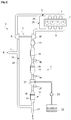
- the device comprises an internal combustion engine 1 which is here of the compression ignition type (diesel), for example direct injection.
- diesel compression ignition type
- the engine 1 is associated with an air intake circuit 2 and an exhaust circuit 3.
- the fresh air taken from the outside atmosphere enters the intake circuit 2 in the direction of arrow E, in an air inlet pipe 4. It can pass through components not shown in the figure such as an air filter.
- the engine 1 comprises a compressor 5 of a turbocharger 6 for supercharging.
- the air passes through the compressor 5 then an intake manifold 7, or distributor 7, of the engine.
- a valve 8 for adjusting the flow of gases admitted to the engine can be fitted between the compressor 5 and the distributor 7, as well as other components not shown, such as for example a charge air cooler.
- the combustion gases from the engine are discharged into an exhaust manifold 9 of the engine, then they pass through the turbine 10 of the turbocharger 6.
- the turbine may be of the type with fixed geometry and associated with an exhaust discharge circuit (not shown) or of the variable geometry type, for adjusting the expansion energy taken by the turbine from the exhaust gases.
- the exhaust gases then pass, from upstream to downstream in their direction of flow: a flowmeter 11 for measuring the mass flow rate of the exhaust gases Qech; an oxidation catalyst 12; a nitrogen oxides trap 13; and, a third gas post-treatment device 14, comprising a particulate filter 15 and a selective reduction catalyst for nitrogen oxides 16, also called an SCR catalyst (acronym for Selective Catalytic Reduction).
- a flowmeter 11 for measuring the mass flow rate of the exhaust gases Qech
- an oxidation catalyst 12 for measuring the mass flow rate of the exhaust gases Qech
- a nitrogen oxides trap 13 a third gas post-treatment device 14 comprising a particulate filter 15 and a selective reduction catalyst for nitrogen oxides 16, also called an SCR catalyst (acronym for Selective Catalytic Reduction).
- SCR catalyst acronym for Selective Catalytic Reduction
- the nitrogen oxides trap 13 is associated with an upstream nitrogen oxides sensor 18 and a downstream nitrogen oxides sensor 19, able to respectively measure a nitrogen oxide concentration value upstream [NOx] in and downstream [NOx] out of the trap.
- concentration of upstream nitrogen oxides is determined by a model mapped as a function of the engine operating point.
- the measurements of the concentration of nitrogen oxides upstream [NOx] in and downstream [NOx] out make it possible, in association with the measurement of the flow rate of the exhaust gases Qech by the flowmeter 11, to determine the mass of oxides of MNOx nitrogen stored in trap 13, as will be detailed below.
- concentration of upstream nitrogen oxides [NOx] in is determined by a model mapped as a function of the engine operating point.
- flow rate of the exhaust gases may be determined by means other than the flowmeter 11.
- a flowmeter may be provided at the intake of the engine, capable of measuring the flow rate of the intake gases Qadm. The flow of exhaust gas is then determined as the sum of said intake gas flow rate and Qcarb fuel flow admitted into the engine.
- the nitrogen oxide trap 13 further comprises heating means 20, for example an electric heating grid 20, capable of rapidly heating the trap to a temperature threshold where the efficiency of the regeneration has at least one minimum value given.
- heating means 20 for example an electric heating grid 20, capable of rapidly heating the trap to a temperature threshold where the efficiency of the regeneration has at least one minimum value given.
- other known heating methods can be envisaged, in particular the degradation of the combustion efficiency of the engine thanks to a delayed injection of fuel into the cylinders of the engine, which can be used alone or in combination with the heating by such a grid. heated.
- the SCR catalyst 16 of the third post-treatment device 14 is supplied with urea-based reducing agents (Adblue®) via a urea injector which injects the urea into a mixer 21 located in the circuit d. 'exhaust 3 upstream of the third post-treatment device 14.
- the reducers generally come from a liquid solution which is stored in a reservoir 22 and which is conveyed to the urea injector by means of a pump 23.
- the third post-treatment device 14 is associated with means for measuring a value representative of the temperature of the SCR catalyst 16 and / or of the urea injector.
- a temperature sensor 24 which is mounted in the exhaust circuit 3 upstream of the third post-treatment device 14.
- a temperature sensor can be provided near the mixer 21 to determine an injector temperature value T.
- a sensor can also be provided at the inlet and / or at the outlet of the third post-treatment device 14 of so as to model the internal temperature of the SCR 16 catalyst, etc.
- oxidation catalyst 12 and the nitrogen oxides trap 13 are combined in one. combined post-treatment device. It is also possible that the particulate filter 15 and the SCR catalyst 16 are separate after-treatment devices.
- the exhaust circuit here comprises a circuit 25 for partial recirculation at high pressure of the exhaust gases at the intake of the engine, also known as the HP EGR circuit (acronym for: Exhaust Gas Recycling - High Pressure).
- HP EGR circuit an Exhaust Gas Recycling - High Pressure
- This circuit originates at a point of the exhaust circuit situated upstream of the turbine 10 and its other end opens at a point of the intake circuit situated downstream of the compressor 5. It comprises a valve 26 for adjusting the gas flow rate. Recycled HP EGR.
- the exhaust circuit further comprises a partial recirculation circuit 27 at low pressure for the exhaust gases at the intake of the engine, also known as the LP EGR circuit (English acronym for: Exhaust Gas Recycling - Low Pressure).
- LP EGR circuit Greek acronym for: Exhaust Gas Recycling - Low Pressure.
- This circuit originates at a point of the exhaust circuit located downstream of the turbine 10, more precisely here after the output of the various post-treatment devices 12, 13, 14, and its other end opens at a point of the circuit d 'inlet located upstream of the compressor 5. It comprises an adjustment valve 28 for the flow of recycled LP EGR gases. It may also include other components, not shown, such as for example a filter, a cooler, etc.
- the operation of the engine is placed under the supervision of an electronic computer (not shown), which determines a certain number of operating parameters of the engine from a plurality of sensors and which controls a plurality of actuators of the engine.
- FIG. 2 there is shown a flowchart of the various steps of the method, according to a non-limiting embodiment thereof.
- the invention is based on the fact that, apart from the regeneration mode in rich mode (at a richness close to 1) which makes it possible to regenerate a trap by emptying it of its NOx thanks to their reduction by fuel, it is also possible to empty a trap of its NOx by simple desorption. For this, it is necessary to cause a sharp and rapid increase in the temperature of the nitrogen oxides trap, accompanied by the addition of a large quantity of reducing agents (in the form of engine fuel). However, it is necessary to keep a richness value which corresponds to a lean mixture operation, because a mixture rich is such as to cause a reduction reaction of NOx, and not the desired desorption reaction.
- the temperature is raised almost instantaneously above a value of the order of 600 to 650 ° C, and the richness is brought to a value close to 0.9, which is greater than the usual operating richness.
- a diesel engine for example between 0.3 and 0.6 on the operating point considered, but which is less than 1, is therefore a lean-mixture operating mode.
- these temperature and richness conditions correspond to those of a conventional purging of a particulate filter by combustion of soot.
- the figure 2 illustrates in detail the steps of the corresponding regeneration method:
- the method begins when the engine is started (step 100).
- the method itself is iterative, and comprises a first step 200 during which a torque setpoint value of the engine C and a speed value of the engine N are determined.
- the speed is measured by a sensor (not shown). on the figure 1 ) mounted on the engine, and the torque setpoint C is mapped from a depression value of an accelerator pedal of the vehicle and from the engine speed.
- the engine computer also deduces from said speed N and from said torque C, set points for the quantity of air Qair, the quantity of high pressure exhaust gas Qegr, hp and low pressure Qegr, lp and of fuel Qcarb to be introduced into the engine.
- the computer adjusts a certain number of engine actuators so as to reach said setpoints: gas flow rate adjustment valve 8; EGR valves 26.28; engine fuel injectors; etc.
- the method continues with a step 300 of calculating the mass of nitrogen oxides stored MNOx in the trap 13.
- the mass of nitrogen oxides at the current time t can be calculated by adding to the value calculated at the previous instant of the iterative process, a value corresponding to the product of the flow rate of the exhaust gases Qech, of the difference between the concentration of upstream nitrogen oxides [NOx] in and the concentration of downstream nitrogen oxides [NOx] out, and of the time step ⁇ t separating the previous instant from the current instant.
- the flow of the exhaust gases Qech comes from a measurement of the flowmeter 11.
- the concentrations of nitrogen oxides upstream [NOx] in and downstream [NOx] out come respectively from measurements of the concentration sensors of nitrogen oxides upstream 18 and downstream 19.
- the calculated value of the mass of nitrogen oxides is initialized to zero at the end of a complete regeneration of the trap.
- the process directs towards a third test step 600 during which it is checked whether the SCR catalyst 16 is effective. Otherwise, that is to say if at least one of the conditions is not met, the process directs towards a fourth test step 700 during which it is also checked whether the SCR catalyst is effective.
- the verification may include the comparison of the temperature T, measured by the temperature sensor 24, with a threshold, typically of the order of 180 ° C to 230 ° C. When said temperature is above said threshold, the urea injector is able to inject reducing agents (Adblue®) upstream of the third post-treatment device 14 and the SCR catalyst 16 has a NOx reduction efficiency which is sufficient.
- step 600 If in step 600, it is concluded that the SCR catalyst is not effective, then the process directs towards a step 800 of regeneration of trap 13 in rich mode (richness close to 1.05) which corresponds to a reduction of NOx . Otherwise, the process directs towards a step 900 of regeneration of the trap by high temperature gradient and supply of lean-mixture fuel, allowing desorption of the NOx, the latter being reduced in the SCR catalyst under the action of Adblue®.
- step 700 If in step 700, it is concluded that the catalyst is not effective, then the process directs towards a waiting step 1100, in which the engine retains its usual lean-mixture operating setting determined in step 200. As soon as the SCR catalyst becomes effective, step 700 continues with step 900.
- the waiting step 1100 corresponds to a step for heating the SCR catalyst 16 which is carried out during cold starts of the engine. For this, we can proceed to actuation of the heating grid 20 of the nitrogen oxide trap and / or to an adjustment of the engine in a combustion mode whose efficiency is degraded, for example by carrying out delayed fuel injections participating in torque production (we speak of close post-injection).
- Such a step is of limited duration (for example about 30 seconds). To prevent the nitrogen oxide trap from exhibiting insufficient NOx storage efficiency during this waiting phase, it is advantageous to provide a sufficient margin on the NOx mass threshold which triggers regeneration of the trap.
- Steps 800 or 900 are preferably continued until trap 13 is fully regenerated.
- the end of regeneration can be signaled by the switching of an oxygen sensor signal (not shown on the figure 1 ) upstream of trap 13. It is also possible to carry out partial regenerations.
- the method resumes at step 200, from which the engine is again set to its usual lean-mixture operating mode, for its current speed-load operating point.
Landscapes
- Engineering & Computer Science (AREA)
- Chemical & Material Sciences (AREA)
- Combustion & Propulsion (AREA)
- Mechanical Engineering (AREA)
- General Engineering & Computer Science (AREA)
- Chemical Kinetics & Catalysis (AREA)
- Health & Medical Sciences (AREA)
- Toxicology (AREA)
- Exhaust Gas After Treatment (AREA)
Applications Claiming Priority (1)
| Application Number | Priority Date | Filing Date | Title |
|---|---|---|---|
| FR1912325A FR3102799B1 (fr) | 2019-11-04 | 2019-11-04 | Procédé de REGENERATION D’UN PIEGE A OXYDES D’AZOTE DE MOTEUR A COMBUSTION INTERNE EQUIPE D’UN CATALYSEUR DE REDUCTION SELECTIVE DES OXYDES D’AZOTE, ET DISPOSITIF ASSOCIE |
Publications (2)
| Publication Number | Publication Date |
|---|---|
| EP3816416A1 true EP3816416A1 (de) | 2021-05-05 |
| EP3816416B1 EP3816416B1 (de) | 2022-07-06 |
Family
ID=69572141
Family Applications (1)
| Application Number | Title | Priority Date | Filing Date |
|---|---|---|---|
| EP20202982.3A Active EP3816416B1 (de) | 2019-11-04 | 2020-10-21 | Verfahren zum regenerieren einer stickoxidfalle eines verbrennungsmotors, der mit einem katalysator zur selektiven reduktion von stickoxiden ausgestattet ist |
Country Status (2)
| Country | Link |
|---|---|
| EP (1) | EP3816416B1 (de) |
| FR (1) | FR3102799B1 (de) |
Citations (9)
| Publication number | Priority date | Publication date | Assignee | Title |
|---|---|---|---|---|
| WO2008047170A1 (en) * | 2006-10-20 | 2008-04-24 | Johnson Matthey Public Limited Company | Thermally regenerable nitric oxide adsorbent |
| FR2926323A1 (fr) | 2008-01-11 | 2009-07-17 | Renault Sas | Procede de gestion d'un piege a oxydes d'azote afin d'assurer un intervalle de vidange minimal |
| FR2985771A3 (fr) | 2012-01-17 | 2013-07-19 | Renault Sa | Regeneration d'un piege a oxydes d'azote |
| FR3029974A1 (fr) | 2014-12-16 | 2016-06-17 | Renault Sa | Procede de purge d'un piege a oxydes d'azote et dispositif de motorisation associe |
| EP3093461A1 (de) * | 2015-05-13 | 2016-11-16 | Mitsubishi Jidosha Kogyo K.K. | Abgasreinigungsvorrichtung für motor |
| US20170074191A1 (en) * | 2015-09-15 | 2017-03-16 | Hyundai Motor Company | METHOD FOR REGENERATING LEAN NOx TRAP OF EXHAUST PURIFICATION SYSTEM PROVIDED WITH LEAN NOx TRAP AND SELECTIVE CATALYTIC REDUCTION CATALYST AND EXHAUST PURIFICATION SYSTEM |
| GB2549000A (en) * | 2016-03-31 | 2017-10-04 | Johnson Matthey Plc | In-exhaust electrical element for NOx storage catalyst and SCR systems |
| DE102018117187A1 (de) * | 2018-07-16 | 2018-08-30 | FEV Europe GmbH | Verfahren zum Betrieb einer Abgasnachbehandlungseinrichtung, Steuereinheit für eine Brennkraftmaschine und Brennkraftmaschine |
| FR3073895A1 (fr) * | 2017-11-17 | 2019-05-24 | Renault S.A.S | Procede de traitement des oxydes d'azote a l'echappement d'un moteur a combustion interne |
-
2019
- 2019-11-04 FR FR1912325A patent/FR3102799B1/fr not_active Expired - Fee Related
-
2020
- 2020-10-21 EP EP20202982.3A patent/EP3816416B1/de active Active
Patent Citations (9)
| Publication number | Priority date | Publication date | Assignee | Title |
|---|---|---|---|---|
| WO2008047170A1 (en) * | 2006-10-20 | 2008-04-24 | Johnson Matthey Public Limited Company | Thermally regenerable nitric oxide adsorbent |
| FR2926323A1 (fr) | 2008-01-11 | 2009-07-17 | Renault Sas | Procede de gestion d'un piege a oxydes d'azote afin d'assurer un intervalle de vidange minimal |
| FR2985771A3 (fr) | 2012-01-17 | 2013-07-19 | Renault Sa | Regeneration d'un piege a oxydes d'azote |
| FR3029974A1 (fr) | 2014-12-16 | 2016-06-17 | Renault Sa | Procede de purge d'un piege a oxydes d'azote et dispositif de motorisation associe |
| EP3093461A1 (de) * | 2015-05-13 | 2016-11-16 | Mitsubishi Jidosha Kogyo K.K. | Abgasreinigungsvorrichtung für motor |
| US20170074191A1 (en) * | 2015-09-15 | 2017-03-16 | Hyundai Motor Company | METHOD FOR REGENERATING LEAN NOx TRAP OF EXHAUST PURIFICATION SYSTEM PROVIDED WITH LEAN NOx TRAP AND SELECTIVE CATALYTIC REDUCTION CATALYST AND EXHAUST PURIFICATION SYSTEM |
| GB2549000A (en) * | 2016-03-31 | 2017-10-04 | Johnson Matthey Plc | In-exhaust electrical element for NOx storage catalyst and SCR systems |
| FR3073895A1 (fr) * | 2017-11-17 | 2019-05-24 | Renault S.A.S | Procede de traitement des oxydes d'azote a l'echappement d'un moteur a combustion interne |
| DE102018117187A1 (de) * | 2018-07-16 | 2018-08-30 | FEV Europe GmbH | Verfahren zum Betrieb einer Abgasnachbehandlungseinrichtung, Steuereinheit für eine Brennkraftmaschine und Brennkraftmaschine |
Also Published As
| Publication number | Publication date |
|---|---|
| EP3816416B1 (de) | 2022-07-06 |
| FR3102799A1 (fr) | 2021-05-07 |
| FR3102799B1 (fr) | 2021-09-24 |
Similar Documents
| Publication | Publication Date | Title |
|---|---|---|
| FR3062418B1 (fr) | Procede de controle des emissions d'oxydes d'azote a l'echappement d'un moteur a combustion interne | |
| EP2134940B1 (de) | Verfahren und vorrichtung zur steuerung des betriebszustandes eines katalysators der abgasstrecke eines verbrennungsmotors | |
| FR3102210A1 (fr) | Procédé de MISE EN ACTION D’UN système DE POST-TRAITEMENT DE MOTEUR A COMBUSTION INTERNE ET DISPOSITIF ASSOCIE | |
| WO2015092180A2 (fr) | Système d'échappement d'un moteur à combustion interne et procédé de chauffage d'un catalyseur scr | |
| EP3535483A1 (de) | System zum einblasen von luft in einen gasauslasskreislauf einer aufgeladenen wärmekraftmaschine | |
| EP3816416B1 (de) | Verfahren zum regenerieren einer stickoxidfalle eines verbrennungsmotors, der mit einem katalysator zur selektiven reduktion von stickoxiden ausgestattet ist | |
| EP3237732B1 (de) | Verfahren zur diagnose einer stickoxidfalle und zugehörige vorrichtung | |
| FR3104199A1 (fr) | PROCEDE DE DIAGNOSTIC DE LA CAPACITE D’OXYDATION D’UN système DE POST-TRAITEMENT DES GAZ DE COMBUSTION D’UN MOTEUR DIESEL, ET DISPOSITIF ASSOCIE | |
| WO2010000981A1 (fr) | Gestion combinee de la regeneration et de la desulfuration pour vehicule automobile | |
| FR2933445A1 (fr) | Gestion combinee de la regeneration et de la desulfuration pour vehicule automobile | |
| FR2933447A1 (fr) | Gestion combinee de la regeneration et de la desulfuration pour vehicule automobile | |
| EP4056820B1 (de) | Verfahren und system zur erkennung von ammoniakleckagen in einem katalysator zur selektiven reduktion von stickoxiden | |
| FR3029571A3 (fr) | Procede de controle d'un dispositif de motorisation et dispositif de motorisation associe | |
| FR3073895A1 (fr) | Procede de traitement des oxydes d'azote a l'echappement d'un moteur a combustion interne | |
| EP2299094A1 (de) | Regelverfahren für einen aufgeladenen Dieselmotor mit Niederdruck-Abgasrückführung | |
| FR2933446A1 (fr) | Gestion combinee de la regeneration et de la desulfuration pour vehicule automobile | |
| EP3330521B1 (de) | Verfahren zur regenerierung einer stickoxidfalle eines verbrennungsmotors | |
| FR2927372A1 (fr) | Procede de commande d'alimentation en carburant d'une ligne d'echappement d'un moteur a combustion et dispositif mettant en oeuvre le procede | |
| EP3224460A1 (de) | Verfahren zur regenerierung eines partikelfilters und beseitigung von schwefel aus einem stickoxidakkumulatoroxidationskatalysator | |
| FR2983531A1 (fr) | Alimentation en mode riche d'un moteur a combustion interne a double pre-injection | |
| EP3020937A1 (de) | Kontrollverfahren einer motorisierungsvorrichtung und entsprechende motorisierungsvorrichtung | |
| FR3102798A1 (fr) | Procédé et système de détermination d’un besoin de chauffe d’un catalyseur de réduction sélective d’oxydes d’azote d’un moteur de véhicule automobile | |
| FR3115820A1 (fr) | Procédé et système de décristallisation d’une ligne d’échappement d’un moteur à combustion interne, notamment Diesel | |
| WO2021069204A1 (fr) | Procede de diagnostic d'un systeme de post-traitement d'un moteur a allumage commande | |
| FR2985771A3 (fr) | Regeneration d'un piege a oxydes d'azote |
Legal Events
| Date | Code | Title | Description |
|---|---|---|---|
| PUAI | Public reference made under article 153(3) epc to a published international application that has entered the european phase |
Free format text: ORIGINAL CODE: 0009012 |
|
| STAA | Information on the status of an ep patent application or granted ep patent |
Free format text: STATUS: THE APPLICATION HAS BEEN PUBLISHED |
|
| AK | Designated contracting states |
Kind code of ref document: A1 Designated state(s): AL AT BE BG CH CY CZ DE DK EE ES FI FR GB GR HR HU IE IS IT LI LT LU LV MC MK MT NL NO PL PT RO RS SE SI SK SM TR |
|
| STAA | Information on the status of an ep patent application or granted ep patent |
Free format text: STATUS: REQUEST FOR EXAMINATION WAS MADE |
|
| 17P | Request for examination filed |
Effective date: 20211102 |
|
| RBV | Designated contracting states (corrected) |
Designated state(s): AL AT BE BG CH CY CZ DE DK EE ES FI FR GB GR HR HU IE IS IT LI LT LU LV MC MK MT NL NO PL PT RO RS SE SI SK SM TR |
|
| GRAP | Despatch of communication of intention to grant a patent |
Free format text: ORIGINAL CODE: EPIDOSNIGR1 |
|
| STAA | Information on the status of an ep patent application or granted ep patent |
Free format text: STATUS: GRANT OF PATENT IS INTENDED |
|
| RIC1 | Information provided on ipc code assigned before grant |
Ipc: F01N 9/00 20060101ALI20220110BHEP Ipc: F01N 3/20 20060101ALI20220110BHEP Ipc: F01N 3/08 20060101AFI20220110BHEP |
|
| INTG | Intention to grant announced |
Effective date: 20220131 |
|
| RAP3 | Party data changed (applicant data changed or rights of an application transferred) |
Owner name: RENAULT S.A.S |
|
| RIN1 | Information on inventor provided before grant (corrected) |
Inventor name: POMES, CHRISTOPHE Inventor name: HENNION, DOMINIQUE |
|
| GRAS | Grant fee paid |
Free format text: ORIGINAL CODE: EPIDOSNIGR3 |
|
| GRAA | (expected) grant |
Free format text: ORIGINAL CODE: 0009210 |
|
| STAA | Information on the status of an ep patent application or granted ep patent |
Free format text: STATUS: THE PATENT HAS BEEN GRANTED |
|
| AK | Designated contracting states |
Kind code of ref document: B1 Designated state(s): AL AT BE BG CH CY CZ DE DK EE ES FI FR GB GR HR HU IE IS IT LI LT LU LV MC MK MT NL NO PL PT RO RS SE SI SK SM TR |
|
| REG | Reference to a national code |
Ref country code: AT Ref legal event code: REF Ref document number: 1503029 Country of ref document: AT Kind code of ref document: T Effective date: 20220715 Ref country code: CH Ref legal event code: EP |
|
| RAP4 | Party data changed (patent owner data changed or rights of a patent transferred) |
Owner name: RENAULT S.A.S |
|
| REG | Reference to a national code |
Ref country code: DE Ref legal event code: R096 Ref document number: 602020003881 Country of ref document: DE |
|
| REG | Reference to a national code |
Ref country code: IE Ref legal event code: FG4D Free format text: LANGUAGE OF EP DOCUMENT: FRENCH |
|
| REG | Reference to a national code |
Ref country code: LT Ref legal event code: MG9D |
|
| REG | Reference to a national code |
Ref country code: NL Ref legal event code: MP Effective date: 20220706 |
|
| PG25 | Lapsed in a contracting state [announced via postgrant information from national office to epo] |
Ref country code: SE Free format text: LAPSE BECAUSE OF FAILURE TO SUBMIT A TRANSLATION OF THE DESCRIPTION OR TO PAY THE FEE WITHIN THE PRESCRIBED TIME-LIMIT Effective date: 20220706 Ref country code: RS Free format text: LAPSE BECAUSE OF FAILURE TO SUBMIT A TRANSLATION OF THE DESCRIPTION OR TO PAY THE FEE WITHIN THE PRESCRIBED TIME-LIMIT Effective date: 20220706 Ref country code: PT Free format text: LAPSE BECAUSE OF FAILURE TO SUBMIT A TRANSLATION OF THE DESCRIPTION OR TO PAY THE FEE WITHIN THE PRESCRIBED TIME-LIMIT Effective date: 20221107 Ref country code: NO Free format text: LAPSE BECAUSE OF FAILURE TO SUBMIT A TRANSLATION OF THE DESCRIPTION OR TO PAY THE FEE WITHIN THE PRESCRIBED TIME-LIMIT Effective date: 20221006 Ref country code: NL Free format text: LAPSE BECAUSE OF FAILURE TO SUBMIT A TRANSLATION OF THE DESCRIPTION OR TO PAY THE FEE WITHIN THE PRESCRIBED TIME-LIMIT Effective date: 20220706 Ref country code: LV Free format text: LAPSE BECAUSE OF FAILURE TO SUBMIT A TRANSLATION OF THE DESCRIPTION OR TO PAY THE FEE WITHIN THE PRESCRIBED TIME-LIMIT Effective date: 20220706 Ref country code: LT Free format text: LAPSE BECAUSE OF FAILURE TO SUBMIT A TRANSLATION OF THE DESCRIPTION OR TO PAY THE FEE WITHIN THE PRESCRIBED TIME-LIMIT Effective date: 20220706 Ref country code: FI Free format text: LAPSE BECAUSE OF FAILURE TO SUBMIT A TRANSLATION OF THE DESCRIPTION OR TO PAY THE FEE WITHIN THE PRESCRIBED TIME-LIMIT Effective date: 20220706 Ref country code: ES Free format text: LAPSE BECAUSE OF FAILURE TO SUBMIT A TRANSLATION OF THE DESCRIPTION OR TO PAY THE FEE WITHIN THE PRESCRIBED TIME-LIMIT Effective date: 20220706 |
|
| REG | Reference to a national code |
Ref country code: AT Ref legal event code: MK05 Ref document number: 1503029 Country of ref document: AT Kind code of ref document: T Effective date: 20220706 |
|
| PG25 | Lapsed in a contracting state [announced via postgrant information from national office to epo] |
Ref country code: PL Free format text: LAPSE BECAUSE OF FAILURE TO SUBMIT A TRANSLATION OF THE DESCRIPTION OR TO PAY THE FEE WITHIN THE PRESCRIBED TIME-LIMIT Effective date: 20220706 Ref country code: IS Free format text: LAPSE BECAUSE OF FAILURE TO SUBMIT A TRANSLATION OF THE DESCRIPTION OR TO PAY THE FEE WITHIN THE PRESCRIBED TIME-LIMIT Effective date: 20221106 Ref country code: HR Free format text: LAPSE BECAUSE OF FAILURE TO SUBMIT A TRANSLATION OF THE DESCRIPTION OR TO PAY THE FEE WITHIN THE PRESCRIBED TIME-LIMIT Effective date: 20220706 Ref country code: GR Free format text: LAPSE BECAUSE OF FAILURE TO SUBMIT A TRANSLATION OF THE DESCRIPTION OR TO PAY THE FEE WITHIN THE PRESCRIBED TIME-LIMIT Effective date: 20221007 |
|
| REG | Reference to a national code |
Ref country code: DE Ref legal event code: R097 Ref document number: 602020003881 Country of ref document: DE |
|
| PG25 | Lapsed in a contracting state [announced via postgrant information from national office to epo] |
Ref country code: SM Free format text: LAPSE BECAUSE OF FAILURE TO SUBMIT A TRANSLATION OF THE DESCRIPTION OR TO PAY THE FEE WITHIN THE PRESCRIBED TIME-LIMIT Effective date: 20220706 Ref country code: RO Free format text: LAPSE BECAUSE OF FAILURE TO SUBMIT A TRANSLATION OF THE DESCRIPTION OR TO PAY THE FEE WITHIN THE PRESCRIBED TIME-LIMIT Effective date: 20220706 Ref country code: DK Free format text: LAPSE BECAUSE OF FAILURE TO SUBMIT A TRANSLATION OF THE DESCRIPTION OR TO PAY THE FEE WITHIN THE PRESCRIBED TIME-LIMIT Effective date: 20220706 Ref country code: CZ Free format text: LAPSE BECAUSE OF FAILURE TO SUBMIT A TRANSLATION OF THE DESCRIPTION OR TO PAY THE FEE WITHIN THE PRESCRIBED TIME-LIMIT Effective date: 20220706 Ref country code: AT Free format text: LAPSE BECAUSE OF FAILURE TO SUBMIT A TRANSLATION OF THE DESCRIPTION OR TO PAY THE FEE WITHIN THE PRESCRIBED TIME-LIMIT Effective date: 20220706 |
|
| PLBE | No opposition filed within time limit |
Free format text: ORIGINAL CODE: 0009261 |
|
| STAA | Information on the status of an ep patent application or granted ep patent |
Free format text: STATUS: NO OPPOSITION FILED WITHIN TIME LIMIT |
|
| PG25 | Lapsed in a contracting state [announced via postgrant information from national office to epo] |
Ref country code: SK Free format text: LAPSE BECAUSE OF FAILURE TO SUBMIT A TRANSLATION OF THE DESCRIPTION OR TO PAY THE FEE WITHIN THE PRESCRIBED TIME-LIMIT Effective date: 20220706 Ref country code: MC Free format text: LAPSE BECAUSE OF FAILURE TO SUBMIT A TRANSLATION OF THE DESCRIPTION OR TO PAY THE FEE WITHIN THE PRESCRIBED TIME-LIMIT Effective date: 20220706 Ref country code: EE Free format text: LAPSE BECAUSE OF FAILURE TO SUBMIT A TRANSLATION OF THE DESCRIPTION OR TO PAY THE FEE WITHIN THE PRESCRIBED TIME-LIMIT Effective date: 20220706 |
|
| 26N | No opposition filed |
Effective date: 20230411 |
|
| REG | Reference to a national code |
Ref country code: BE Ref legal event code: MM Effective date: 20221031 |
|
| PG25 | Lapsed in a contracting state [announced via postgrant information from national office to epo] |
Ref country code: LU Free format text: LAPSE BECAUSE OF NON-PAYMENT OF DUE FEES Effective date: 20221021 Ref country code: AL Free format text: LAPSE BECAUSE OF FAILURE TO SUBMIT A TRANSLATION OF THE DESCRIPTION OR TO PAY THE FEE WITHIN THE PRESCRIBED TIME-LIMIT Effective date: 20220706 |
|
| P01 | Opt-out of the competence of the unified patent court (upc) registered |
Effective date: 20230608 |
|
| PG25 | Lapsed in a contracting state [announced via postgrant information from national office to epo] |
Ref country code: SI Free format text: LAPSE BECAUSE OF FAILURE TO SUBMIT A TRANSLATION OF THE DESCRIPTION OR TO PAY THE FEE WITHIN THE PRESCRIBED TIME-LIMIT Effective date: 20220706 |
|
| PG25 | Lapsed in a contracting state [announced via postgrant information from national office to epo] |
Ref country code: BE Free format text: LAPSE BECAUSE OF NON-PAYMENT OF DUE FEES Effective date: 20221031 |
|
| PG25 | Lapsed in a contracting state [announced via postgrant information from national office to epo] |
Ref country code: IE Free format text: LAPSE BECAUSE OF NON-PAYMENT OF DUE FEES Effective date: 20221021 |
|
| REG | Reference to a national code |
Ref country code: GB Ref legal event code: 732E Free format text: REGISTERED BETWEEN 20231228 AND 20240103 |
|
| PG25 | Lapsed in a contracting state [announced via postgrant information from national office to epo] |
Ref country code: IT Free format text: LAPSE BECAUSE OF FAILURE TO SUBMIT A TRANSLATION OF THE DESCRIPTION OR TO PAY THE FEE WITHIN THE PRESCRIBED TIME-LIMIT Effective date: 20220706 |
|
| PGFP | Annual fee paid to national office [announced via postgrant information from national office to epo] |
Ref country code: FR Payment date: 20231026 Year of fee payment: 4 Ref country code: DE Payment date: 20231020 Year of fee payment: 4 |
|
| PG25 | Lapsed in a contracting state [announced via postgrant information from national office to epo] |
Ref country code: CY Free format text: LAPSE BECAUSE OF FAILURE TO SUBMIT A TRANSLATION OF THE DESCRIPTION OR TO PAY THE FEE WITHIN THE PRESCRIBED TIME-LIMIT Effective date: 20220706 |
|
| REG | Reference to a national code |
Ref country code: DE Ref legal event code: R081 Ref document number: 602020003881 Country of ref document: DE Owner name: NEW H POWERTRAIN HOLDING, S.L.U., ES Free format text: FORMER OWNER: RENAULT S.A.S., BOULOGNE BILLANCOURT, FR |
|
| PG25 | Lapsed in a contracting state [announced via postgrant information from national office to epo] |
Ref country code: MK Free format text: LAPSE BECAUSE OF FAILURE TO SUBMIT A TRANSLATION OF THE DESCRIPTION OR TO PAY THE FEE WITHIN THE PRESCRIBED TIME-LIMIT Effective date: 20220706 |
|
| REG | Reference to a national code |
Ref country code: CH Ref legal event code: PL |
|
| PG25 | Lapsed in a contracting state [announced via postgrant information from national office to epo] |
Ref country code: CH Free format text: LAPSE BECAUSE OF NON-PAYMENT OF DUE FEES Effective date: 20231031 |
|
| PG25 | Lapsed in a contracting state [announced via postgrant information from national office to epo] |
Ref country code: HU Free format text: LAPSE BECAUSE OF FAILURE TO SUBMIT A TRANSLATION OF THE DESCRIPTION OR TO PAY THE FEE WITHIN THE PRESCRIBED TIME-LIMIT; INVALID AB INITIO Effective date: 20201021 Ref country code: CH Free format text: LAPSE BECAUSE OF NON-PAYMENT OF DUE FEES Effective date: 20231031 Ref country code: BG Free format text: LAPSE BECAUSE OF FAILURE TO SUBMIT A TRANSLATION OF THE DESCRIPTION OR TO PAY THE FEE WITHIN THE PRESCRIBED TIME-LIMIT Effective date: 20220706 |
|
| PG25 | Lapsed in a contracting state [announced via postgrant information from national office to epo] |
Ref country code: MT Free format text: LAPSE BECAUSE OF FAILURE TO SUBMIT A TRANSLATION OF THE DESCRIPTION OR TO PAY THE FEE WITHIN THE PRESCRIBED TIME-LIMIT Effective date: 20220706 |