EP3816018A1 - Ridden work vehicle - Google Patents
Ridden work vehicle Download PDFInfo
- Publication number
- EP3816018A1 EP3816018A1 EP19827079.5A EP19827079A EP3816018A1 EP 3816018 A1 EP3816018 A1 EP 3816018A1 EP 19827079 A EP19827079 A EP 19827079A EP 3816018 A1 EP3816018 A1 EP 3816018A1
- Authority
- EP
- European Patent Office
- Prior art keywords
- vertically oriented
- oriented transmission
- hydraulic cylinder
- vehicle body
- vehicle
- Prior art date
- Legal status (The legal status is an assumption and is not a legal conclusion. Google has not performed a legal analysis and makes no representation as to the accuracy of the status listed.)
- Pending
Links
Images





Classifications
-
- B—PERFORMING OPERATIONS; TRANSPORTING
- B60—VEHICLES IN GENERAL
- B60G—VEHICLE SUSPENSION ARRANGEMENTS
- B60G17/00—Resilient suspensions having means for adjusting the spring or vibration-damper characteristics, for regulating the distance between a supporting surface and a sprung part of vehicle or for locking suspension during use to meet varying vehicular or surface conditions, e.g. due to speed or load
-
- B—PERFORMING OPERATIONS; TRANSPORTING
- B62—LAND VEHICLES FOR TRAVELLING OTHERWISE THAN ON RAILS
- B62D—MOTOR VEHICLES; TRAILERS
- B62D7/00—Steering linkage; Stub axles or their mountings
- B62D7/18—Steering knuckles; King pins
-
- B—PERFORMING OPERATIONS; TRANSPORTING
- B60—VEHICLES IN GENERAL
- B60G—VEHICLE SUSPENSION ARRANGEMENTS
- B60G17/00—Resilient suspensions having means for adjusting the spring or vibration-damper characteristics, for regulating the distance between a supporting surface and a sprung part of vehicle or for locking suspension during use to meet varying vehicular or surface conditions, e.g. due to speed or load
- B60G17/015—Resilient suspensions having means for adjusting the spring or vibration-damper characteristics, for regulating the distance between a supporting surface and a sprung part of vehicle or for locking suspension during use to meet varying vehicular or surface conditions, e.g. due to speed or load the regulating means comprising electric or electronic elements
-
- B—PERFORMING OPERATIONS; TRANSPORTING
- B60—VEHICLES IN GENERAL
- B60G—VEHICLE SUSPENSION ARRANGEMENTS
- B60G3/00—Resilient suspensions for a single wheel
- B60G3/01—Resilient suspensions for a single wheel the wheel being mounted for sliding movement, e.g. in or on a vertical guide
-
- B—PERFORMING OPERATIONS; TRANSPORTING
- B60—VEHICLES IN GENERAL
- B60K—ARRANGEMENT OR MOUNTING OF PROPULSION UNITS OR OF TRANSMISSIONS IN VEHICLES; ARRANGEMENT OR MOUNTING OF PLURAL DIVERSE PRIME-MOVERS IN VEHICLES; AUXILIARY DRIVES FOR VEHICLES; INSTRUMENTATION OR DASHBOARDS FOR VEHICLES; ARRANGEMENTS IN CONNECTION WITH COOLING, AIR INTAKE, GAS EXHAUST OR FUEL SUPPLY OF PROPULSION UNITS IN VEHICLES
- B60K17/00—Arrangement or mounting of transmissions in vehicles
- B60K17/22—Arrangement or mounting of transmissions in vehicles characterised by arrangement, location, or type of main drive shafting, e.g. cardan shaft
- B60K17/24—Arrangement of mountings for shafting
-
- B—PERFORMING OPERATIONS; TRANSPORTING
- B60—VEHICLES IN GENERAL
- B60K—ARRANGEMENT OR MOUNTING OF PROPULSION UNITS OR OF TRANSMISSIONS IN VEHICLES; ARRANGEMENT OR MOUNTING OF PLURAL DIVERSE PRIME-MOVERS IN VEHICLES; AUXILIARY DRIVES FOR VEHICLES; INSTRUMENTATION OR DASHBOARDS FOR VEHICLES; ARRANGEMENTS IN CONNECTION WITH COOLING, AIR INTAKE, GAS EXHAUST OR FUEL SUPPLY OF PROPULSION UNITS IN VEHICLES
- B60K17/00—Arrangement or mounting of transmissions in vehicles
- B60K17/30—Arrangement or mounting of transmissions in vehicles the ultimate propulsive elements, e.g. ground wheels, being steerable
-
- B—PERFORMING OPERATIONS; TRANSPORTING
- B60—VEHICLES IN GENERAL
- B60K—ARRANGEMENT OR MOUNTING OF PROPULSION UNITS OR OF TRANSMISSIONS IN VEHICLES; ARRANGEMENT OR MOUNTING OF PLURAL DIVERSE PRIME-MOVERS IN VEHICLES; AUXILIARY DRIVES FOR VEHICLES; INSTRUMENTATION OR DASHBOARDS FOR VEHICLES; ARRANGEMENTS IN CONNECTION WITH COOLING, AIR INTAKE, GAS EXHAUST OR FUEL SUPPLY OF PROPULSION UNITS IN VEHICLES
- B60K17/00—Arrangement or mounting of transmissions in vehicles
- B60K17/34—Arrangement or mounting of transmissions in vehicles for driving both front and rear wheels, e.g. four wheel drive vehicles
-
- B—PERFORMING OPERATIONS; TRANSPORTING
- B60—VEHICLES IN GENERAL
- B60K—ARRANGEMENT OR MOUNTING OF PROPULSION UNITS OR OF TRANSMISSIONS IN VEHICLES; ARRANGEMENT OR MOUNTING OF PLURAL DIVERSE PRIME-MOVERS IN VEHICLES; AUXILIARY DRIVES FOR VEHICLES; INSTRUMENTATION OR DASHBOARDS FOR VEHICLES; ARRANGEMENTS IN CONNECTION WITH COOLING, AIR INTAKE, GAS EXHAUST OR FUEL SUPPLY OF PROPULSION UNITS IN VEHICLES
- B60K17/00—Arrangement or mounting of transmissions in vehicles
- B60K17/34—Arrangement or mounting of transmissions in vehicles for driving both front and rear wheels, e.g. four wheel drive vehicles
- B60K17/358—Arrangement or mounting of transmissions in vehicles for driving both front and rear wheels, e.g. four wheel drive vehicles all driven wheels being steerable
-
- B—PERFORMING OPERATIONS; TRANSPORTING
- B62—LAND VEHICLES FOR TRAVELLING OTHERWISE THAN ON RAILS
- B62D—MOTOR VEHICLES; TRAILERS
- B62D49/00—Tractors
- B62D49/06—Tractors adapted for multi-purpose use
-
- B—PERFORMING OPERATIONS; TRANSPORTING
- B62—LAND VEHICLES FOR TRAVELLING OTHERWISE THAN ON RAILS
- B62D—MOTOR VEHICLES; TRAILERS
- B62D49/00—Tractors
- B62D49/06—Tractors adapted for multi-purpose use
- B62D49/0607—Straddle tractors, used for instance above vine stocks, rows of bushes, or the like
-
- B—PERFORMING OPERATIONS; TRANSPORTING
- B60—VEHICLES IN GENERAL
- B60G—VEHICLE SUSPENSION ARRANGEMENTS
- B60G2200/00—Indexing codes relating to suspension types
- B60G2200/40—Indexing codes relating to the wheels in the suspensions
- B60G2200/422—Driving wheels or live axles
-
- B—PERFORMING OPERATIONS; TRANSPORTING
- B60—VEHICLES IN GENERAL
- B60G—VEHICLE SUSPENSION ARRANGEMENTS
- B60G2200/00—Indexing codes relating to suspension types
- B60G2200/40—Indexing codes relating to the wheels in the suspensions
- B60G2200/44—Indexing codes relating to the wheels in the suspensions steerable
-
- B—PERFORMING OPERATIONS; TRANSPORTING
- B60—VEHICLES IN GENERAL
- B60G—VEHICLE SUSPENSION ARRANGEMENTS
- B60G2202/00—Indexing codes relating to the type of spring, damper or actuator
- B60G2202/40—Type of actuator
- B60G2202/41—Fluid actuator
- B60G2202/413—Hydraulic actuator
-
- B—PERFORMING OPERATIONS; TRANSPORTING
- B60—VEHICLES IN GENERAL
- B60G—VEHICLE SUSPENSION ARRANGEMENTS
- B60G2300/00—Indexing codes relating to the type of vehicle
- B60G2300/08—Agricultural vehicles
- B60G2300/082—Tractors
-
- B—PERFORMING OPERATIONS; TRANSPORTING
- B60—VEHICLES IN GENERAL
- B60G—VEHICLE SUSPENSION ARRANGEMENTS
- B60G2400/00—Indexing codes relating to detected, measured or calculated conditions or factors
- B60G2400/25—Stroke; Height; Displacement
- B60G2400/252—Stroke; Height; Displacement vertical
-
- B—PERFORMING OPERATIONS; TRANSPORTING
- B60—VEHICLES IN GENERAL
- B60G—VEHICLE SUSPENSION ARRANGEMENTS
- B60G2500/00—Indexing codes relating to the regulated action or device
- B60G2500/30—Height or ground clearance
-
- B—PERFORMING OPERATIONS; TRANSPORTING
- B60—VEHICLES IN GENERAL
- B60Y—INDEXING SCHEME RELATING TO ASPECTS CROSS-CUTTING VEHICLE TECHNOLOGY
- B60Y2200/00—Type of vehicle
- B60Y2200/20—Off-Road Vehicles
- B60Y2200/22—Agricultural vehicles
- B60Y2200/221—Tractors
-
- F—MECHANICAL ENGINEERING; LIGHTING; HEATING; WEAPONS; BLASTING
- F15—FLUID-PRESSURE ACTUATORS; HYDRAULICS OR PNEUMATICS IN GENERAL
- F15B—SYSTEMS ACTING BY MEANS OF FLUIDS IN GENERAL; FLUID-PRESSURE ACTUATORS, e.g. SERVOMOTORS; DETAILS OF FLUID-PRESSURE SYSTEMS, NOT OTHERWISE PROVIDED FOR
- F15B18/00—Parallel arrangements of independent servomotor systems
Definitions
- the present invention is directed to a riding work vehicle having a plurality of traveling wheels.
- a traveling vehicle body includes a vehicle body frame, a plurality of traveling wheels and an engine which drives the plurality of traveling wheels, power from the engine is transmitted to the traveling wheels via a horizontally oriented transmission shaft and a vertically oriented transmission shaft, and the traveling wheels are supported to be changeable in direction about a rotational axis of the vertically oriented transmission shaft relative to the vehicle body frame.
- the vertically oriented transmission shaft and a vertically oriented case for covering this vertically oriented transmission shaft are formed long in the vertical direction, thus being designed for high clearance by securing a large ground clearance for the traveling vehicle body.
- the vertically oriented case has a double tubular construction comprised of an upper case portion and a lower case portion, with the upper case portion being fixed to the vehicle body frame, and the lower case portion being changeable in direction together with the traveling wheels.
- the vertical length of the vertically oriented case is set to a constant length which is set in advance (see Patent Literature 1 for example).
- a traveling vehicle body includes a vehicle body frame and a plurality of traveling wheels, and the traveling wheels are supported to the vehicle body frame via a tubular support member which extends in the vertical direction.
- a riding work vehicle which travels while carrying out a utility work in a field is sometimes provided with a stroke sensor having an expandable/contractable operation arrangement like a hydraulic cylinder in order to detect an expansion/contraction operation amount of the hydraulic cylinder when e.g. an operation of changing a ground clearance of the traveling vehicle body is effected with using the hydraulic cylinder providing a large operational force.
- a stroke sensor having a fixed electrode and a movable electrode both provided inside a storage case and configured to detect the expansion/contraction operation amount electrically based on a change amount occurring in an electrostatic capacitance which varies in association with an expansion/contraction movement of the hydraulic cylinder see e.g. Patent Literature 3).
- the work vehicle having the conventional configuration is capable of driving the traveling wheel via the vertically oriented transmission shaft and is capable also of smoothly changing the direction of the traveling wheel by pivoting the vertically oriented case about the axis of the vertically oriented transmission shaft.
- the vertical length of the vertically oriented case is fixed, i.e. constant, there would occur inconvenience that excess or shortage of ground clearance of the traveling vehicle body may occur due to e.g. a difference in the growth state of the agricultural produces, a difference in the utility work situation, etc.
- the growth state of the produces is favorable, thus having a large height, an accidental contact between the vehicle body and the produces may occur if the ground clearance remains unchanged.
- the ground clearance of the traveling vehicle body may be so high that the posture thereof may become unstable, for instance.
- the configuration is to electrically detect an electrostatic capacitance between electrodes, if the configuration is used under a condition subject to possible intrusion of water or application of violent vibration thereto, the possibility of trouble will be high.
- the configuration is disadvantageous in terms of durability in case it is used in a work vehicle for outdoor use.
- a riding work vehicle comprising:
- the vertically oriented transmission shaft and the vertically oriented transmission case respectively expand or contract slidably.
- the relative height of the traveling wheel relative to the vehicle body frame can be changed and adjusted.
- the ground clearance of the traveling vehicle body can be changed.
- the vertically oriented transmission case is pivotable together with the traveling wheels, with whatever position the ground clearance of the traveling vehicle body may be changed to, the direction (orientation) of the traveling wheels can be changed smoothly by pivoting the vertically oriented transmission case. Moreover, transmission of rotational power to the traveling wheels is possible even when the vertically oriented transmission shaft is expanded/contracted.
- the vehicle body side case includes a support boss portion for pivotally supporting the vertically oriented transmission case; and the support boss portion extends downwards along the direction of the axis of the vertically oriented transmission shaft on a radial inner side of the vertically oriented transmission case.
- the vertically oriented transmission case is pivotally supported. Since the support boss portion is provided to extend downwards along the direction of the axis of the vertically oriented transmission shaft on a radial inner side of the vertically oriented transmission case, it is possible to allow the traveling wheels to support the vehicle body in a stable manner with effective prevention of reduction in the supporting strength for the vertically oriented transmission case due to the expandable/contractible arrangement and to allow a turning operation of the traveling wheels to proceed in a favorable manner.
- the vertically oriented transmission case is provided as a structure which expands/contracts in association with mutual sliding between the inner tubular member and the outer tubular member thereof in order to constitute an expandable/contractible structure. Further, since the vehicle height adjustment mechanism includes a plurality of hydraulic cylinders that extend along the axial direction, the expanding/contracting operation of the vertically oriented transmission case can be made smoothly without risk of twisting or the like.
- the vertically oriented transmission case when expanded, presents a reduced width along the expanding/contracting direction at its overlap portion where the inner tubular member and the outer tubular member are overlapped with each other. This may present a risk of reduction in the strength in supporting the traveling wheels due to reduction in the rigidity.
- the base member included in the vehicle height adjustment mechanism to support the outer circumferential side of the overlap portion of the vertically oriented transmission case, such reduction in the rigidity can be effectively prevented.
- a riding work vehicle comprising:
- the relative position of the traveling wheels relative to the vehicle body frame can be changed in a plurality of steps.
- the plurality of hydraulic cylinders are arranged at positions differing in the circumferential direction and in opposition to each other across the support member therebetween, on an outer circumferential side of the support member, the support member receives operational forces from the plurality of hydraulic cylinders uniformly, so that the support member can be expanded/contracted in a smooth manner without such disadvantage of being twisted with application of unbalanced load thereto.
- a manual coupling operation for position fixing is not required as this can be coped with expansion/contraction of the hydraulic cylinders, so that no great trouble is required.
- the vehicle height adjustment mechanism in operation of the vehicle height adjustment mechanism, when the upper hydraulic cylinder is expanded/contracted, the area upwardly of the base member is expanded/contracted. Whereas, when the lower hydraulic cylinder is expanded/contracted, the area downwardly of the base member is expanded/contracted.
- the vehicle height adjustment mechanism can be switched to a maximal length state elongate in the vertical direction.
- both the upper hydraulic cylinder and the lower hydraulic cylinder are contracted, the vehicle height adjustment mechanism can be switched to a minimal length state short in the vertical direction.
- the vehicle height adjustment mechanism can be switched to an intermediate length state located between the maximal length state and the minimal length state.
- each hydraulic cylinder employed can be a compact one having a short expansion/contraction amount (stroke)
- the expansion/contraction amount of the vehicle height adjustment mechanism as a whole can be made long (large).
- the vehicle height adjustment mechanism can be switched in the three stages of the minimal length state, the intermediate length state and the maximal length state.
- the work oil when the work oil is fed from a work oil supply source to the upper hydraulic cylinder, the work oil can be fed via the communication oil passage not only to the upper hydraulic cylinder, but also to the lower hydraulic cylinder. And, by switching over between the opened state and the closed state of the communication oil passage, the upper hydraulic cylinder and the lower hydraulic cylinder can be operated sequentially or the upper hydraulic cylinder and the lower hydraulic cylinder can be operated simultaneously, etc. In this way, various uses are possible depending on a difference in the work situation, so that there is achieved greater convenience.
- the communication oil passage is formed to extend through the inside of the base member.
- the vehicle height adjustment mechanism can be operated in a favorable manner without such disadvantage of the expanding/contracting operation being blocked by a pipe or the like, or durability of the pipe being reduced, etc.
- a riding work vehicle comprising:
- the arrangement detects an expansion/contraction operation amount based on the rotational count of a screw shaft obtained via a mechanical sliding contact action between the screw shaft and the sliding contact member, even a simple arrangement will suffice for the purpose, so that cost reduction is made possible. Moreover, even if water should enter from the outside, the arrangement would be hardly affected by the water, thus being superior in the durability.
- the operation amount detecting means is accommodated in the inside of the hydraulic cylinder whose circumference is covered, it is possible to prevent rainwater, muddy water or the like from coming or falling onto the operation amount detecting means, so that the durability can be further improved.
- the operation amount detecting means is accommodated in the inside of the hydraulic cylinder to directly detect the amount of relative movement between the cylinder tube and the piston rod. Therefore, the detection of the expansion/contraction operation amount is made possible with effective utilization of a member provided originally in the hydraulic cylinder.
- Fig. 1 shows a riding work vehicle according to the present invention.
- the work vehicle includes, at a rear portion of a four-wheel traveling type traveling vehicle body 1, a chemical agent spraying device 2 as an implement (utility implement).
- the work vehicle is configured to carry out a utility work of spraying chemical agent onto agricultural produces while traveling across a planting row of the produces, in a field where such produces are planted in advance.
- a pair of front wheels 3 as “traveling wheels S” capable of turning
- a pair of rear wheels 4 as the "traveling wheels S” capable of turning.
- all of the four wheels can effect turning (i.e. being steerable). So that, it is possible to switch over e.g. between a two-wheel steering state in which only the two front wheels 3 are steered and a four-wheel steering state in which the front wheels 3 and the rear wheels 4 are steered in the opposite directions from each other, to make a turn with a small turning radius.
- the front wheels 3 and the rear wheels 4 are formed with narrow width so as to allow traveling between ridges which are located between planting rows.
- an engine 5 is mounted and at a rear portion of the traveling vehicle body 1, a driving section 6 is provided.
- a transmission case 7 accommodating an unillustrated speed changer mechanism for changing the speed of power from the engine 5.
- the transmission case 7 is provided to extend in the front/rear direction from a rear lower part of the engine 5 to a position corresponding to the rear wheels 4 as seen in the side view.
- a front side frame body 8 is provided to cover the outer circumferential portion thereof.
- the transmission case 7 and the font side frame body 8 are connected integrally to each other, thereby to constitute a vehicle body frame F which supports the entire vehicle body.
- the driving section 6 includes a driver's seat 9 at which a driver is seated and a steering wheel 10 disposed forwardly of the driver's seat 9 for effecting a steering operation.
- the driving section 6 further includes a lift lever 11 for lifting the implement up/down, a speed changer lever 12 and so on.
- the traveling vehicle body 1 power from the engine 5 is speed-changed by the speed changer device provided inside the transmission case 7 and then transmitted to the right and left front wheels 3 and the right and left rear wheels 4.
- the traveling vehicle body 1 is configured as a four-wheel drive type having four traveling wheels S being driven.
- a tubular, rear horizontally oriented transmission case 13 (one example of "vehicle body side case") connected to the right and left opposed sides of the transmission case 7, there is provided a horizontally oriented transmission shaft 14, so that speed-changed power is transmitted to the right and left rear wheels 4 via the horizontally oriented transmission shaft 14.
- the rear horizontally oriented transmission case 13 is supported to the transmission case 7, namely, to the vehicle body frame F.
- a tubular, front horizontally oriented transmission case 15 (an example of the "vehicle body side case", to be referred to also simply as “horizontally oriented transmission case 15” hereinafter), so that the power from the transmission case 7 is transmitted to the right and left front wheels 3 via a front/rear oriented intermediate shaft 16, a differential mechanism (not shown) provided inside the horizontally oriented transmission case 15 and a horizontally oriented transmission shaft 18.
- the front horizontally oriented transmission case 15 is supported to the vehicle body frame F to be capable of rolling about a front/rear axis X extending concentric with the intermediate shaft 16.
- each vertically oriented transmission case 19 is connected (each acting as an example of a "support member").
- a vertically oriented transmission shaft 20 inside each vertically oriented transmission case 19, there is provided a vertically oriented transmission shaft 20.
- An axial end portion of the horizontally oriented transmission shaft 18 in the front horizontally oriented transmission case 15 is operably coupled to an upper end portion of the vertically oriented transmission shaft 20 via an upper bevel gear mechanism 21.
- a lower end portion of the vertically oriented transmission shaft 20 is operably coupled to a rotational shaft 3a of the front wheel 3 via a lower bevel gear mechanism 22.
- the traveling wheel S is supported to the vehicle body frame F to be direction-changeable about a rotational axis Y of the vertically oriented transmission shaft 20. Since the wheel support arrangement, including the vertically oriented transmission case 19 and the vertically oriented transmission shaft 20, has an identical construction for each one of the four traveling wheels S, the support arrangement only for one front wheel 3 as one of them will be described next.
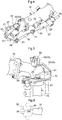
- the terminal end of the front horizontally oriented transmission case 15 presents a curved bent shape as seen in a front view to cover the upper bevel gear mechanism 21 and defines an opening which opens downwards.
- an upper connection body 23 which is connected integrally to the upper end portion of the vertically oriented transmission case 19, is engaged and connected to an end portion of the front horizontally oriented transmission case 15 to be pivotable about the rotational axis Y of the vertically oriented transmission shaft 20.
- a wheel support case 24 for covering the lower bevel gear mechanism 22 and also for supporting the rotational shaft 3a of the front wheel 3.
- a retainer 25 is provided for preventing inadvertent removal of the upper connection body 23 under its engaged and connected state.
- the retainer 25 is formed of a strip member, and has one end portion thereof bolt-connected to the outer circumferential portion of the upper connection body 23, and the other end portion thereof engaged with a stepped portion 26 which is formed at the terminal end of the front horizontally oriented transmission case 15 for preventing the removal.
- a double-action type hydraulic cylinder 27 for steering operation (to be referred to as "steering cylinder 27" hereinafter) which is located forwardly of the front horizontally oriented transmission case 15 and under a posture parallel with the front horizontally oriented transmission case 15.
- a cylinder tube 28 of the steering cylinder 27 is coupled with the front horizontally oriented transmission case 15 via a bracket 29.
- a piston rod 30 of the steering cylinder 27 is operably coupled to one end portion of a tie rod 32 via a ball joint 31 and the other end portion of the tie rod 32 is operably coupled via a ball joint 33 with a knuckle arm 34 included in the upper connection body 23.
- the steering cylinder 27 When the steering cylinder 27 is operated, via the knuckle arm 34 and the upper connection body 23, the vertically oriented transmission case 19, the wheel support case 24 and the front wheel 3 respectively pivot together about the rotational axis Y of the vertically oriented transmission shaft 20, whereby the direction (orientation) of the front wheel 3 is changed.
- the steering cylinder 27 In response to an operation on the steering wheel 10, the steering cylinder 27 has its hydraulic control valve switched by an unillustrated control device, thus being slid under oil pressure from a neutral position for straight traveling to the left direction or the right direction.
- a pivot angle detection device 35 for detecting a pivot angle of the upper connection body 23, namely, a pivot angle of the front wheel 3.
- This pivot angle detection device 35 includes a potentiometer type detection device body 36 fixedly provided at the upper part of the front horizontally oriented transmission case 15, and a strip-like operational arm 37.
- the operational arm 37 has one end portion thereof bolt-connected to the outer circumferential portion of the upper connection body 23, and the other end portion thereof engaged and coupled with a rotational shaft 38 protruding downwards from the detection device body 36.
- the detection device body 36 has its outer circumference covered by a casing 39, and the casing 39 is coupled to the upper part of the terminal end of the front horizontally oriented transmission case 15.
- the operational arm 37 is provided to extend obliquely upwards from its portion coupled with the upper connection body 23.
- the rotational shaft 38 is worked to provide a rectangular shape cross section, so that the rotational shaft 38 is operatively coupled to be rotated together with the operational arm 37, through engagement with a rectangular shape engagement groove 40 formed at the other end portion of the operational arm 37.
- a pivot restriction portion 41 for restricting the range of pivotal operation of the upper connection body 23.
- an upper protrusion portion 42 formed in the upper connection body 23 is configured to allow the pivotal operation thereof within the range set by the pivot restriction portion 41.
- the upper connection body 23 In response to an operation of the steering cylinder 27, the upper connection body 23, thus the vertically oriented transmission case 19 and the front wheel 3, can be pivoted within the operational range restricted by the pivot restriction portion 41. Then, the pivot operation angle of the upper connection body 23 is detected by the pivot angle detection device 35 and fed back to the unillustrated control device, whereby the steering cylinder 27 will be controlled to provide a steering angle corresponding to the operation of the steering wheel 10.
- each of the vertically oriented transmission shaft 20 and the vertically oriented transmission case 19 is provided as an inner/outer double structure which can be expanded/contracted while sliding in the direction of the axis of the vertically oriented transmission shaft 20.
- the vertically oriented transmission case 19 includes an outer tubular member 19A and an inner tubular member 19B, so that the case 19 is expandable/contractible in association with sliding movements of these members.
- the vertically oriented transmission case 19 is provided in such a manner that the outer tubular member 19A is located on the lower side and the inner tubular member 19B is located on the upper side.
- the lower end portion of the outer tubular member 19A is integrally coupled with the wheel support case 24 and the upper end portion of the inner tubular member 19B is integrally coupled with the upper connection body 23.
- the vertically oriented transmission shaft 20 includes a tubular shaft 20A, and an inner shaft 20B which is slidable in the axis direction with maintaining a state of being spline-engaged with the inner side of the tubular shaft 20A to be rotatable therewith.
- An upper end portion of the inner shaft 20B is coupled with the upper bevel gear mechanism 21 to be rotatable therewith.
- the lower end portion of the tubular shaft 20A is coupled with the lower bevel gear mechanism 22 to be rotatable therewith.
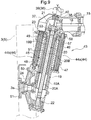
- a hydraulic operation type vehicle height adjustment mechanism 43 configured to be capable of switching the relative height of the front wheel 3 relative to the vehicle body frame F in a plurality of steps by expanding/contracting the vertically oriented transmission shaft 20 and the vertically oriented transmission case 19 in the direction of the rotational axis Y of the vertically oriented transmission shaft 20.
- the vehicle height adjustment mechanism 43 includes a plurality of hydraulic cylinders 44 which extend along the direction of the axis of the vertically oriented transmission shaft 20, and a base member 45 for supporting the plurality of hydraulic cylinders 44.
- the plurality of hydraulic cylinders 44 are arranged at positions which differ from each other in the circumferential direction on the outer circumference side of the vertically oriented transmission case 19 and in opposition to each other across the vertically oriented transmission case 19 therebetween.
- the plurality of hydraulic cylinders 44 there are provided two upper hydraulic cylinders 44a which can be expanded/contracted toward the upper side relative to the base member 45, and two lower hydraulic cylinders 44b which can be expanded/contracted toward the lower side relative to the base member 45.
- the two upper hydraulic cylinders 44a are arranged at positions which differ from each other in the circumferential direction on the outer circumference side of the vertically oriented transmission case 19 and in opposition to each other across the vertically oriented transmission case 19 therebetween.
- the two lower hydraulic cylinders 44b are arranged at positions which differ from each other in the circumferential direction on the outer circumference side of the vertically oriented transmission case 19 and in opposition to each other across the vertically oriented transmission case 19 therebetween.
- each of the lower hydraulic cylinders 44b is disposed to be located at approximately intermediate portion in the circumferential direction of the two upper hydraulic cylinders 44a as seen in the axial direction thereof.
- Each of the upper hydraulic cylinders 44a is provided with the piston rod 46 thereof being located on the upper side and the cylinder tube 47 thereof being located on the lower side.
- Each of the lower hydraulic cylinders 44b is provided with the piston rod 48 thereof being located on the lower side and the cylinder tube 49 thereof being located on the upper side.
- the leading end portions of the piston rods 46 of the two upper hydraulic cylinders 44a are integrally coupled with the upper connection body 23, and the leading end portions of the piston rods 48 of the two lower hydraulic cylinders 44b are integrally coupled with the wheel support case 24.
- the cylinder tubes 47 of the two upper hydraulic cylinders 44a and the cylinder tubes 49 of the two lower hydraulic cylinders 44b are integrally coupled with the base member 45. Whereby, the upper hydraulic cylinders 44a are located on the upper side relative to the base member 45 and the lower hydraulic cylinders 44b are located on the lower side relative to the base member 45.
- the upper end portion of the vertically oriented transmission case 19 and the upper end portions of the two upper hydraulic cylinders 44a are integrally coupled with the upper connection body 23 and the lower end portions of the two lower hydraulic cylinders 44b are integrally coupled with the vehicle support case 24. Further, the cylinder tubes 47 of the two upper hydraulic cylinders 44a and the cylinder tubes 49 of the two lower hydraulic cylinders 44b are integrally coupled with the base member 45. Therefore, the upper connection body 23 and the wheel support case 24 are integrally coupled with each other via the four hydraulic cylinders 44 and the base member 45. So that, when the steering cylinder 27 is operated, these members are pivoted together to thereby steer the front wheel 3.
- a support boss portion 51 for pivotally supporting the inner side of the vertically oriented transmission case 19 is provided to be located on the radially inner side of the vertically oriented transmission case 19 and to extend downwards along the direction of the rotational axis Y.
- the support boss portion 51 configured to pivotally support the inner circumferential side of the upper connection body 23 is formed to extend integrally downwards along the direction of the axis of the vertically oriented transmission shaft 20.
- the support boss portion 51 pivotally supports, via a bearing 53, the vertically oriented transmission shaft 20 which is located on the inner circumferential side.
- the support boss portion 51 is provided to extend elongate downwards to reach the lower side than the vertical intermediate portion of the inner tubular member 19B. In this way, as the vertically elongate support boss portion 51 supports the vertically oriented transmission case 19 from the inner circumference side, reduction in the supporting strength for the vertically oriented transmission case 19 is prevented.
- a communication oil passage 56 which extends through the inside of the base member 45 to connect an oil chamber 54 of the upper hydraulic cylinder 44a to an oil chamber 55 of the lower hydraulic cylinder 44b.
- the vehicle height adjustment mechanism 43 is configured to be switchable between a "sequential operation mode" in which work oil is fed to the oil chamber 54 of the upper hydraulic cylinder 44a with switching the communication oil passage 56 to its closed state to expand the upper hydraulic cylinder 44a and then the communication oil passage 56 is switched over to its opened state for feeding work oil to the oil chamber 55 of the lower hydraulic cylinder 44b and a "simultaneous operation mode" in which, with switching the communication oil passage 56 to the opened state, the work oil is fed simultaneously to the oil chamber 54 of the upper hydraulic cylinder 44a and the oil chamber 55 of the lower hydraulic cylinder 44b.
- an inner oil passage 57 is formed in the shaft inner portion of the piston rod 46 of the upper hydraulic cylinder 44a integrally coupled with the upper connection body 23.
- the upper connection body 23 defines a work oil feed opening 58, and the work oil feed opening 58 is communicated and connected to the inner oil passage 57.
- the work oil is fed to the work oil feed opening 58 via an oil pressure control valve from a hydraulic pump provided in the traveling vehicle body 1.
- the inner oil passage 57 is formed in the inner shaft portion of the piston rod 46 in this way, the work oil can be fed to the inside of the oil chambers with utilization of the inner oil passage 57, whereby there is no need to provide any special external piping or the like to extend from the work oil feed opening 58, so that simplification of the hydraulic piping is realized.
- a communication oil passage 56 is formed integrally in the base member 45 for communicating the oil chamber 54 provided inside the cylinder tube 47 of the upper hydraulic cylinder 44a and the oil chamber 55 provided inside the cylinder tube 49 of the lower hydraulic cylinder 44b.
- an electromagnetic operation type opening/closing valve 59 At a passage intermediate portion of the communication oil passage 56, there is incorporated an electromagnetic operation type opening/closing valve 59.
- the work oil will be fed from the oil chambers 54 of the cylinder tubes 47 of the upper hydraulic cylinders 44a via the communication oil passage 56 to the oil chambers 55 of the cylinder tubes 49 of the lower hydraulic cylinders 44b.
- This operational mode in which the mode is switched over from the shortest state via the intermediately expanded state to the maximally expanded state is the sequential operation mode. Therefore, in this sequential operation mode, the ground clearance (vehicle height) of the traveling vehicle body 1 can be switched over in three steps of: the low position (shortest state), the intermediate position (intermediately expanded state) and the high position (maximally expanded state).
- the switchover between the sequential operation mode and the simultaneous operation mode can be effected by a mode switching tool provided in the driving section 6 and a vehicle height changing operation can be effected by a vehicle height changing tool also provided in the driving section 6.
- the unillustrated control device will control the operations for switching the oil pressure control valve and the opening/closing valve 59 to the corresponding states, responsive to operations of the mode switching tool and the vehicle height changing tool.
- the arrangement is not limited to the arrangement having both the sequential operation mode and the simultaneous operation mode respectively, but may be an arrangement having only one of them.
- a stroke sensor 60 (an example of "operation amount detecting means") located on the inner side in the vehicle body lateral width direction of the vertically oriented transmission case 19 and extending vertically long the extending direction of the vertically oriented transmission case 19.
- the stroke sensor 60 is provided between the upper connection body 23, and a support bracket 61 provided at a lower part of the wheel support case 24.
- an outer tube 62 (an example of a "first member") which is relatively moved in association with expanding/contracting movements of the four hydraulic cylinders 44 and an inner tube 63 (an example of a “second member”) which is slidably fitted within the outer tube 62.
- a tubular sliding member 64 having a cylinder structure forming a closed space therein, with closing of the terminal ends of the outer tube 62 and the inner tube 63 which terminal ends are exposed to the outside.
- the upper end portion of the outer tube 62 is coupled to the upper connection body 23 and the lower end portion of the inner tube 63 is coupled with the support bracket 61.
- the tubular sliding member 64 accommodates therein the stroke sensor 60.
- the stroke sensor 60 includes a screw shaft 66 provided in the outer tube 62 to be movable in unison therewith and having a helical blade 65 integrally fixed to its outer circumferential portion; a sliding contact member 67 provided in the inner tube 63 and configured to come into sliding contact with the helical blade 65 in association with a relative movement between the outer tube 62 and the inner tube 63 for guiding the screw shaft 66 for its rotation; and an electromagnetic type pickup sensor 68 as a "rotation detection sensor” capable of detecting a rotational count of the screw shaft 66.
- the helical blade 65 may be formed integrally with the outer tube 62 or may be firstly produced separately of the outer tube 62 and then fixedly attached thereto.
- the screw shaft 66 is supported by a support portion 69 provided at the upper end portion of the outer tube 62 to be movable in unison therewith along the axial direction and also pivotable in the circumferential direction.
- the screw shaft 66 is extended along the inside of the inner tube 63.
- the sliding contact member 67 fitted over the screw shaft 66 and configured to come into sliding contact with the helical blade 65.
- a detection gear 70 i.e. gear for detection
- the outer tube 62 includes the electromagnetic type pickup sensor 68 having the well-known arrangement at a portion thereof corresponding to the outer circumferential portion of the detection gear 70.
- Such pickup sensor 68 is widely used in agricultural machines or other devices and can detect a rotational count accurately and reliably.
- the helical blade 65 of the screw shaft 66 receives a sliding contact action of the sliding contact member 67 and the screw shaft 66 is rotated by a rotational amount corresponding to the amount of movement.
- the pickup sensor 68 can detect the rotational count of the screw shaft 66 based on waveform of electric current which is generated at the time of passing of a tooth of the detection gear 70 associated with rotation of the screw shaft 66.
- the present invention is applicable to a riding work vehicle having a plurality of traveling wheels.
Landscapes
- Engineering & Computer Science (AREA)
- Mechanical Engineering (AREA)
- Chemical & Material Sciences (AREA)
- Combustion & Propulsion (AREA)
- Transportation (AREA)
- Vehicle Body Suspensions (AREA)
- Physics & Mathematics (AREA)
- Fluid Mechanics (AREA)
- General Engineering & Computer Science (AREA)
Abstract
Description
- The present invention is directed to a riding work vehicle having a plurality of traveling wheels.
- According to a riding work vehicle known in the art, a traveling vehicle body includes a vehicle body frame, a plurality of traveling wheels and an engine which drives the plurality of traveling wheels, power from the engine is transmitted to the traveling wheels via a horizontally oriented transmission shaft and a vertically oriented transmission shaft, and the traveling wheels are supported to be changeable in direction about a rotational axis of the vertically oriented transmission shaft relative to the vehicle body frame.
- As an example of the riding work vehicle of the above-noted type, there is known one in which the vertically oriented transmission shaft and a vertically oriented case for covering this vertically oriented transmission shaft are formed long in the vertical direction, thus being designed for high clearance by securing a large ground clearance for the traveling vehicle body. The vertically oriented case has a double tubular construction comprised of an upper case portion and a lower case portion, with the upper case portion being fixed to the vehicle body frame, and the lower case portion being changeable in direction together with the traveling wheels. And the vertical length of the vertically oriented case is set to a constant length which is set in advance (see
Patent Literature 1 for example). - With this configuration, in such a case where a fertilizer feeding device or a chemical spraying device is attached to a rear portion of the traveling vehicle body and there is carried out a work of feeding fertilizer or insecticide chemical to agricultural produces while the vehicle travels in a field with the right and left traveling wheels thereof striding over a ridge therebetween, thanks to the high setting of the ground clearance of the traveling vehicle body, the traveling can proceed with involving no contact between the vehicle body and the ridge formed in the field or the agricultural produces planted in the field.
- As an example of the riding work vehicle of the above-noted type, there is known one in which a traveling vehicle body includes a vehicle body frame and a plurality of traveling wheels, and the traveling wheels are supported to the vehicle body frame via a tubular support member which extends in the vertical direction.
- As an example of the riding work vehicle of the above-noted type, there is known one in which the vertically oriented transmission shaft and the vertically oriented case acting as the tubular support member for covering this vertically oriented transmission shaft are formed long in the vertical direction, thus being designed for high clearance by securing a large ground clearance for the traveling vehicle body (see e.g. Patent Literature 1).
- With this configuration, in such a case where a fertilizer feeding device or a chemical spraying device is attached to a rear portion of the traveling vehicle body and there is carried out a work of feeding fertilizer or insecticide chemical to agricultural produces while the vehicle travels in a field with the right and left traveling wheels thereof striding over a ridge therebetween, thanks to the high setting of the ground clearance of the traveling vehicle body, the traveling can proceed with involving no contact between the vehicle body and the ridge formed in the field or the agricultural produces planted in the field.
- A riding work vehicle which travels while carrying out a utility work in a field is sometimes provided with a stroke sensor having an expandable/contractable operation arrangement like a hydraulic cylinder in order to detect an expansion/contraction operation amount of the hydraulic cylinder when e.g. an operation of changing a ground clearance of the traveling vehicle body is effected with using the hydraulic cylinder providing a large operational force. And, as an example of such stroke sensor of the above-noted type, there is known a stroke sensor having a fixed electrode and a movable electrode both provided inside a storage case and configured to detect the expansion/contraction operation amount electrically based on a change amount occurring in an electrostatic capacitance which varies in association with an expansion/contraction movement of the hydraulic cylinder (see e.g. Patent Literature 3).
-
- Patent Literature 1:
JP2003-094907A - Patent Literature 2:
JP7-195902A - Patent Literature 3:
JP2018-063239A - Object relating to [Background Art 1] is as follows.
- The work vehicle having the conventional configuration is capable of driving the traveling wheel via the vertically oriented transmission shaft and is capable also of smoothly changing the direction of the traveling wheel by pivoting the vertically oriented case about the axis of the vertically oriented transmission shaft. However, with the conventional configuration, since the vertical length of the vertically oriented case is fixed, i.e. constant, there would occur inconvenience that excess or shortage of ground clearance of the traveling vehicle body may occur due to e.g. a difference in the growth state of the agricultural produces, a difference in the utility work situation, etc. For instance, if the growth state of the produces is favorable, thus having a large height, an accidental contact between the vehicle body and the produces may occur if the ground clearance remains unchanged. Besides, when the work vehicle travels over a ridge in the course of its entrance to or exit from the field, if the ground clearance remains unchanged, the ground clearance of the traveling vehicle body may be so high that the posture thereof may become unstable, for instance.
- Then, there has been a need for ability to set the ground clearance of the traveling vehicle body to an optimal height in accordance with such difference in the growth state of the agricultural produces, a difference in the working situation, etc., thus allowing a rotational driving and a turning operation of the traveling wheels to take place in a favorable manner.
- Object relating to [Background Art 2] is as follows.
- With the conventional configuration described above, since the vertical length of the vertically oriented case is fixed to be constant, there would occur inconvenience that excess or shortage of ground clearance of the traveling vehicle body may occur due to e.g. a difference in the growth state of the produces, a difference in the working situation, etc. For instance, if the growth state of the produces is favorable, thus having a large height, an accidental contact between the vehicle body and the produces may occur if the ground clearance remains unchanged. Besides, when the work vehicle travels over a ridge in the course of its entrance to or exit from the field, if the ground clearance remains unchanged, the ground clearance of the traveling vehicle body may be so high that the posture thereof may become unstable, for instance.
- Incidentally, as an arrangement for changing the ground clearance of the traveling vehicle body, there has been proposed an arrangement that allows change of the ground clearance of the traveling vehicle body by changing an attaching position of a wheel support case for supporting a rotational shaft of the traveling wheel to the vertically oriented transmission case as a tubular support member for supporting the traveling wheel (see e.g. Patent Literature 2). Specifically, the wheel support case is attached in such a manner that the rotational shaft of the traveling wheel is provided offset (eccentric) relative to an output shaft of the vertically oriented transmission case and the wheel support case is position-changeable by pivoting about the axis of the output shaft and then fixed in position with a bolt.
- However, with such arrangement involving change of attaching position of the wheel support case, there would occur a large sliding resistance between the vertically oriented case and the wheel support case, and for coping with the risk of smooth pivotal operation of the wheel support case becoming impossible, e.g. a troublesome work of fixing with the bolt would be required. Moreover, the adjustment amount possible for change in the ground clearance of the traveling vehicle body is not sufficient, thus presenting inconvenience.
- Then, there has been a need for ability to set the ground clearance of the traveling vehicle body to an optimal height in accordance with such difference in the growth state of the produces, a difference in the working situation, etc., without requiring great trouble and with smoothness.
- Object relating to [Background Art 3] is as follows.
- With the conventional configuration described above, it is necessary to form the fixed electrode and the movable electrode within the storage case with high precision. Also, there is a need for a capacitance detecting circuit or the like for detecting an electrostatic capacitance, so that the configuration would tend to be complicated and disadvantageous in terms of cost. Moreover, since the configuration is to electrically detect an electrostatic capacitance between electrodes, if the configuration is used under a condition subject to possible intrusion of water or application of violent vibration thereto, the possibility of trouble will be high. Thus, the configuration is disadvantageous in terms of durability in case it is used in a work vehicle for outdoor use.
- Then, there has been a need for ability to detect an expansion/contraction operation amount of a hydraulic cylinder at low cost and with superior durability even in the case of outdoor use.
- A solution corresponding to [Object 1] is as below.
- A riding work vehicle comprising:
- a traveling vehicle body;
- a vehicle body frame included in the traveling vehicle frame and configured to support a vehicle body side case;
- a plurality of traveling wheels supported to the vehicle body frame to be changeable in direction about a rotational axis of a vertically oriented transmission shaft;
- an engine provided in the traveling vehicle body for driving the respective traveling wheels with power transmitted via the vertically oriented transmission shaft;
- a vertically oriented transmission case configured to over the circumference of the vertically oriented transmission shaft;
- each of the vertically oriented transmission shaft and the vertically oriented transmission case is provided as an inner/outer double structure which is expandable/contractible while sliding in a direction of an axis of the vertically oriented transmission shaft;
- the vertically oriented transmission case being supported to the vehicle body side case to be pivotable together with the traveling wheels about the rotational axis of the vertically oriented transmission shaft; and
- a vehicle height adjustment mechanism capable of switching a relative height of the traveling wheels relative to the vehicle body frame in a plurality of steps by expanding/contracting the vertically oriented transmission shaft and the vertically oriented transmission case in the direction of the axis of the vertically oriented transmission shaft.
- With the above-described configuration, with an operation of the vehicle height adjustment mechanism, the vertically oriented transmission shaft and the vertically oriented transmission case respectively expand or contract slidably. With this, the relative height of the traveling wheel relative to the vehicle body frame can be changed and adjusted. And, with such height adjustment of the respective one of the plurality of traveling wheels, the ground clearance of the traveling vehicle body can be changed.
- Thus, with the above-described arrangement of slidable contraction/expansion of the vertically oriented transmission case and the vertically oriented transmission case respectively, in comparison with e.g. an arrangement of supporting the traveling wheels with allowing elevation and lowering thereof via use of e.g. a refractive link or the like, although the arrangement does not protrude significantly to the lateral outer side and has a compact shape as seen in a plan view, the arrangement yet allows long setting for the adjustable amount of the vehicle height.
- Further, since the vertically oriented transmission case is pivotable together with the traveling wheels, with whatever position the ground clearance of the traveling vehicle body may be changed to, the direction (orientation) of the traveling wheels can be changed smoothly by pivoting the vertically oriented transmission case. Moreover, transmission of rotational power to the traveling wheels is possible even when the vertically oriented transmission shaft is expanded/contracted.
- Therefore, it has become possible to set the ground clearance of the traveling vehicle body to an optimal height in accordance with such difference in the growth state of the produces, a difference in the working situation, etc., while allowing a rotational driving and a turning operation of the traveling wheels to take place in a favorable manner.
- According to one preferred embodiment, the vehicle body side case includes a support boss portion for pivotally supporting the vertically oriented transmission case; and
the support boss portion extends downwards along the direction of the axis of the vertically oriented transmission shaft on a radial inner side of the vertically oriented transmission case. - With the above-described arrangement, with the support boss portion provided in the vehicle body side case, the vertically oriented transmission case is pivotally supported. Since the support boss portion is provided to extend downwards along the direction of the axis of the vertically oriented transmission shaft on a radial inner side of the vertically oriented transmission case, it is possible to allow the traveling wheels to support the vehicle body in a stable manner with effective prevention of reduction in the supporting strength for the vertically oriented transmission case due to the expandable/contractible arrangement and to allow a turning operation of the traveling wheels to proceed in a favorable manner.
- According to one preferred embodiment:
- the vehicle height adjustment mechanism includes a plurality of hydraulic cylinders extending along the direction of the axis of the vertically oriented transmission shaft and a base member for supporting the plurality of hydraulic cylinders;
- the vertically oriented transmission case is provided as an inner/outer double structure that can be expanded/contracted in association with mutual sliding between an inner tubular member and an outer tubular member thereof; and
- when the vertically oriented transmission case is expanded maximally, an outer circumferential side of an overlap portion where the inner tubular member and the outer tubular member are overlapped with each other is supported by the base member.
- With the above-described arrangement, the vertically oriented transmission case, is provided as a structure which expands/contracts in association with mutual sliding between the inner tubular member and the outer tubular member thereof in order to constitute an expandable/contractible structure. Further, since the vehicle height adjustment mechanism includes a plurality of hydraulic cylinders that extend along the axial direction, the expanding/contracting operation of the vertically oriented transmission case can be made smoothly without risk of twisting or the like.
- The vertically oriented transmission case, when expanded, presents a reduced width along the expanding/contracting direction at its overlap portion where the inner tubular member and the outer tubular member are overlapped with each other. This may present a risk of reduction in the strength in supporting the traveling wheels due to reduction in the rigidity. However, with use of the base member included in the vehicle height adjustment mechanism to support the outer circumferential side of the overlap portion of the vertically oriented transmission case, such reduction in the rigidity can be effectively prevented.
- Therefore, with effective utilization of the base member required for supporting the plurality of hydraulic cylinders in the vehicle height adjustment mechanism, it has become possible to support the traveling wheels in a stable manner with prevention of reduction in the supporting strength of the vertically oriented transmission case.
- A solution corresponding to [Object 2] is as below.
- A riding work vehicle comprising:
- a traveling vehicle body;
- a vehicle body frame;
- a plurality of traveling wheels; and
- a tubular support member for supporting the traveling wheels to the vehicle body frame, the support member being expandable/contractible in a vertical direction;
- wherein there is provided a hydraulic operation type vehicle height adjustment mechanism capable of switching, in a plurality of steps, a relative height of the traveling wheels relative to the vehicle body frame by expanding/contracting the support member;
- the vehicle height adjustment mechanism includes a plurality of hydraulic cylinders that can be expanded/contracted along an expanding/contracting direction of the support member; and
- the plurality of hydraulic cylinders are arranged in opposition to each other across the support member therebetween, on an outer circumferential side of the support member.
- With the above-described arrangement, when the support member is expanded/contracted in the vertical direction by the vehicle height adjustment mechanism having a plurality of hydraulic cylinders, the relative position of the traveling wheels relative to the vehicle body frame can be changed in a plurality of steps. As the plurality of hydraulic cylinders are arranged at positions differing in the circumferential direction and in opposition to each other across the support member therebetween, on an outer circumferential side of the support member, the support member receives operational forces from the plurality of hydraulic cylinders uniformly, so that the support member can be expanded/contracted in a smooth manner without such disadvantage of being twisted with application of unbalanced load thereto. Moreover, e.g. a manual coupling operation for position fixing is not required as this can be coped with expansion/contraction of the hydraulic cylinders, so that no great trouble is required.
- Thus, it has become possible to set the ground clearance of the traveling vehicle body to an optimal height in accordance with such difference in the growth state of the produces, a difference in the working situation, etc., without requiring great trouble and with smoothness.
- According to one preferred embodiment:
- the vehicle height adjustment mechanism includes a base member which is located at a vertically intermediate portion of the support member for supporting the plurality of hydraulic cylinders;
- each said hydraulic cylinder includes an upper hydraulic cylinder expandable upwards relative to the base member and a lower hydraulic cylinder expandable downwards relative to the base member; and
- the upper hydraulic cylinder and the lower hydraulic cylinder are disposed at different positions with respect to the circumferential direction of the support member.
- With the above-described arrangement, in operation of the vehicle height adjustment mechanism, when the upper hydraulic cylinder is expanded/contracted, the area upwardly of the base member is expanded/contracted. Whereas, when the lower hydraulic cylinder is expanded/contracted, the area downwardly of the base member is expanded/contracted. When both the upper hydraulic cylinder and the lower hydraulic cylinder are expanded, the vehicle height adjustment mechanism can be switched to a maximal length state elongate in the vertical direction. When both the upper hydraulic cylinder and the lower hydraulic cylinder are contracted, the vehicle height adjustment mechanism can be switched to a minimal length state short in the vertical direction. And, when either one of the upper hydraulic cylinder and the lower hydraulic cylinder is expanded and the other thereof is contracted, the vehicle height adjustment mechanism can be switched to an intermediate length state located between the maximal length state and the minimal length state.
- With the above-described arrangement, although each hydraulic cylinder employed can be a compact one having a short expansion/contraction amount (stroke), the expansion/contraction amount of the vehicle height adjustment mechanism as a whole can be made long (large). Moreover, by making selection between a state of feeding work oil to a maximal state and a state of discharging the work oil, for the plurality of hydraulic cylinders, with a simple oil pressure feeding arrangement of switching over between the state of feeding the work oil and the state of discharging the work oil, without effecting any special position control, the vehicle height adjustment mechanism can be switched in the three stages of the minimal length state, the intermediate length state and the maximal length state.
- According to one preferred embodiment:
- the vehicle height adjustment mechanism includes a communication oil passage which connects an oil chamber of the upper hydraulic cylinder to an oil chamber of the lower hydraulic cylinder;
- the vehicle height adjustment mechanism is configured to be switchable between a sequential operation mode and a simultaneous operation mode;
- when the communication oil passage has been switched to a closed state, the vehicle height adjustment mechanism, under the sequential operation mode, feeds the work oil to the oil chamber of the upper hydraulic cylinder to expand this upper hydraulic cylinder and then switches the communication oil passage to an opened state to feed the work oil to the oil chamber of the lower hydraulic cylinder; and
- when the communication oil passage has been switched to the opened state, the vehicle height adjustment mechanism, under the simultaneous operation mode, feeds the work oil simultaneously to the oil chamber of the upper hydraulic cylinder and the oil chamber of the lower hydraulic cylinder.
- With the above-described arrangement, when the work oil is fed from a work oil supply source to the upper hydraulic cylinder, the work oil can be fed via the communication oil passage not only to the upper hydraulic cylinder, but also to the lower hydraulic cylinder. And, by switching over between the opened state and the closed state of the communication oil passage, the upper hydraulic cylinder and the lower hydraulic cylinder can be operated sequentially or the upper hydraulic cylinder and the lower hydraulic cylinder can be operated simultaneously, etc. In this way, various uses are possible depending on a difference in the work situation, so that there is achieved greater convenience.
- According to one preferred embodiment, the communication oil passage is formed to extend through the inside of the base member.
- With the above-described arrangement, as the communication oil passage is formed inside the base member, there is no need for any special oil pipe which takes a roundabout route on the outside. Thus, the vehicle height adjustment mechanism can be operated in a favorable manner without such disadvantage of the expanding/contracting operation being blocked by a pipe or the like, or durability of the pipe being reduced, etc.
- A solution corresponding to [Object 3] is as below.
- A riding work vehicle comprising:
- a traveling vehicle body;
- a vehicle body frame;
- a traveling wheel supported to the traveling vehicle body, with relative height thereof relative to the vehicle body frame being changeable;
- a hydraulic cylinder configured to be capable of switching over the relative height of the traveling wheel relative to the vehicle body frame;
- an operation amount detecting means for detecting an expansion/contraction operation amount of the hydraulic cylinder; and
- a first member and a second member which move relative to each other in association with expansion/contraction of the hydraulic cylinder;
- wherein the operation amount detecting means includes:
- a screw shaft configured to be movable together with one of the first member and the second member, the screw shaft having a helical blade on an outer circumferential portion thereof;
- a sliding contact member provided in the other of the first member and the second member, the sliding contact member coming into sliding contact with the helical blade in association with relative movement between the first member and the second member, thereby to rotatably guide the screw shaft; and
- a rotation detection sensor configured to be capable of detecting a rotational count of the screw shaft; and
- wherein the expansion/contraction operation amount of the hydraulic cylinder is detected based on the rotational count detected by the rotation detection sensor.
- With the above-described arrangement, when the hydraulic cylinder is expanded/contracted, the first member and the second member move relative to each other in correspondence therewith and the sliding contact member provided in the other one of the first member and the second member comes into sliding contact with the helical blade of the screw shaft provided in the one member, thereby to rotate the screw shaft. And, as the rotation detection senser detects the rotational count of the screw shaft, and based on this rotational count, the expansion/contraction operation amount of the hydraulic cylinder is detected. Such rotational count of the screw shaft has a value which corresponds to the amount of the relative movement between the first member and the second member. As such rotation detection sensor, it is possible to employ e.g. an electromagnetic pickup sensor or the like widely used for detection of rotation of a transmission shaft in e.g. an agricultural work vehicle and having high reliability.
- In this way, since the arrangement detects an expansion/contraction operation amount based on the rotational count of a screw shaft obtained via a mechanical sliding contact action between the screw shaft and the sliding contact member, even a simple arrangement will suffice for the purpose, so that cost reduction is made possible. Moreover, even if water should enter from the outside, the arrangement would be hardly affected by the water, thus being superior in the durability.
- Accordingly, it has become possible to detect an expansion/contraction operation amount of a hydraulic cylinder at low cost and with superior durability even in outdoor use.
- According to one preferred embodiment:
- there is provided a tubular sliding member having an outer tube as the first member and an inner tube as the second member slidably engaged within the outer tube;
- inside the tubular sliding member, there is formed a closed space as end portions of the outer tube and the inner tube exposed to the outside are closed; and
- the operation amount detecting means is accommodated in the inside of the tubular sliding member.
- With the above-described arrangement, since the operation amount detecting means is accommodated in the inside of the hydraulic cylinder whose circumference is covered, it is possible to prevent rainwater, muddy water or the like from coming or falling onto the operation amount detecting means, so that the durability can be further improved.
- According to one preferred embodiment:
- the operation amount detecting means is accommodated in the inside of the hydraulic cylinder;
- a cylinder tube of the hydraulic cylinder functions as the first member; and
- a piston rod of the hydraulic cylinder functions as the second member.
- With the above-described arrangement, since the hydraulic cylinder is provided with the cylinder tube and the piston rod which move relative to each other in association with an expanding/contracting operation, the operation amount detecting means is accommodated in the inside of the hydraulic cylinder to directly detect the amount of relative movement between the cylinder tube and the piston rod. Therefore, the detection of the expansion/contraction operation amount is made possible with effective utilization of a member provided originally in the hydraulic cylinder.
- Further and other characterizing features and advantages resulting therefrom will become apparent upon reading the following detailed description.
-
-
Fig. 1 is an overall side view of a work vehicle, -
Fig. 2 is a plan view showing a wheel supporting structure of the work vehicle, -
Fig. 3 is a front view showing the wheel supporting structure, -
Fig. 4 is a perspective view showing a part of the wheel supporting structure, -
Fig. 5 is a perspective view showing another part of the wheel supporting structure, -
Fig. 6 is a plan view showing an engagement state of an operational arm, -
Fig. 7 is a front view in horizontal section showing a vehicle height adjustment mechanism under its maximally expanded state, -
Fig. 8 is a front view in horizontal section showing the vehicle height adjustment mechanism under its intermediately expanded state, -
Fig. 9 is a front view in horizontal section showing the vehicle height adjustment mechanism under its shortest state, -
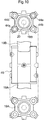
Fig. 10 is a view showing a base member, -
Fig. 11 is a plan view in horizontal section showing the base member, -
Fig. 12 is a view in section showing an arrangement of a stroke sensor, and -
Fig. 13 is a view in section showing an arrangement of a stroke sensor according to a further embodiment. - Embodiments of a riding work vehicle according to the present invention will be described with reference to the drawings.
-
Fig. 1 shows a riding work vehicle according to the present invention. The work vehicle includes, at a rear portion of a four-wheel traveling type travelingvehicle body 1, a chemicalagent spraying device 2 as an implement (utility implement). The work vehicle is configured to carry out a utility work of spraying chemical agent onto agricultural produces while traveling across a planting row of the produces, in a field where such produces are planted in advance. - On the right and left sides of the front portion of the traveling
vehicle body 1, there are provided a pair offront wheels 3 as "traveling wheels S" capable of turning, and on the right and left sides of the rear portion of the travelingvehicle body 1, there are provided a pair ofrear wheels 4 as the "traveling wheels S" capable of turning. In this way, all of the four wheels can effect turning (i.e. being steerable). So that, it is possible to switch over e.g. between a two-wheel steering state in which only the twofront wheels 3 are steered and a four-wheel steering state in which thefront wheels 3 and therear wheels 4 are steered in the opposite directions from each other, to make a turn with a small turning radius. - The
front wheels 3 and therear wheels 4 are formed with narrow width so as to allow traveling between ridges which are located between planting rows. At a front portion of the travelingvehicle body 1, anengine 5 is mounted and at a rear portion of the travelingvehicle body 1, adriving section 6 is provided. Downwardly of the travelingvehicle body 1, there is provided atransmission case 7 accommodating an unillustrated speed changer mechanism for changing the speed of power from theengine 5. Thetransmission case 7 is provided to extend in the front/rear direction from a rear lower part of theengine 5 to a position corresponding to therear wheels 4 as seen in the side view. On the lower side of theengine 5, a frontside frame body 8 is provided to cover the outer circumferential portion thereof. Thetransmission case 7 and the fontside frame body 8 are connected integrally to each other, thereby to constitute a vehicle body frame F which supports the entire vehicle body. Thedriving section 6 includes a driver'sseat 9 at which a driver is seated and asteering wheel 10 disposed forwardly of the driver'sseat 9 for effecting a steering operation. Thedriving section 6 further includes alift lever 11 for lifting the implement up/down, aspeed changer lever 12 and so on. - In the traveling
vehicle body 1, power from theengine 5 is speed-changed by the speed changer device provided inside thetransmission case 7 and then transmitted to the right and leftfront wheels 3 and the right and leftrear wheels 4. Whereby, the travelingvehicle body 1 is configured as a four-wheel drive type having four traveling wheels S being driven. As shown inFig. 2 , inside a tubular, rear horizontally oriented transmission case 13 (one example of "vehicle body side case") connected to the right and left opposed sides of thetransmission case 7, there is provided a horizontally orientedtransmission shaft 14, so that speed-changed power is transmitted to the right and leftrear wheels 4 via the horizontally orientedtransmission shaft 14. The rear horizontally orientedtransmission case 13 is supported to thetransmission case 7, namely, to the vehicle body frame F. - As shown in
Fig. 2 , at a right/left intermediate portion of the right and leftfront wheels 3, there is provided a tubular, front horizontally oriented transmission case 15 (an example of the "vehicle body side case", to be referred to also simply as "horizontally orientedtransmission case 15" hereinafter), so that the power from thetransmission case 7 is transmitted to the right and leftfront wheels 3 via a front/rear orientedintermediate shaft 16, a differential mechanism (not shown) provided inside the horizontally orientedtransmission case 15 and a horizontally orientedtransmission shaft 18. The front horizontally orientedtransmission case 15 is supported to the vehicle body frame F to be capable of rolling about a front/rear axis X extending concentric with theintermediate shaft 16. - As shown in
Fig. 3 , to the right/left end portions of the front horizontally orientedtransmission case 15, vertically orientedtransmission cases 19 are connected (each acting as an example of a "support member"). As shown inFig. 7 , inside each vertically orientedtransmission case 19, there is provided a vertically orientedtransmission shaft 20. An axial end portion of the horizontally orientedtransmission shaft 18 in the front horizontally orientedtransmission case 15 is operably coupled to an upper end portion of the vertically orientedtransmission shaft 20 via an upperbevel gear mechanism 21. A lower end portion of the vertically orientedtransmission shaft 20 is operably coupled to arotational shaft 3a of thefront wheel 3 via a lowerbevel gear mechanism 22. - And the traveling wheel S is supported to the vehicle body frame F to be direction-changeable about a rotational axis Y of the vertically oriented
transmission shaft 20. Since the wheel support arrangement, including the vertically orientedtransmission case 19 and the vertically orientedtransmission shaft 20, has an identical construction for each one of the four traveling wheels S, the support arrangement only for onefront wheel 3 as one of them will be described next. - As shown in
Figs. 4, 5 and7 , the terminal end of the front horizontally orientedtransmission case 15 presents a curved bent shape as seen in a front view to cover the upperbevel gear mechanism 21 and defines an opening which opens downwards. For covering the opening, anupper connection body 23, which is connected integrally to the upper end portion of the vertically orientedtransmission case 19, is engaged and connected to an end portion of the front horizontally orientedtransmission case 15 to be pivotable about the rotational axis Y of the vertically orientedtransmission shaft 20. As shown inFig. 7 , to the lower end portion of the vertically orientedtransmission case 19, there is connected awheel support case 24 for covering the lowerbevel gear mechanism 22 and also for supporting therotational shaft 3a of thefront wheel 3. - A
retainer 25 is provided for preventing inadvertent removal of theupper connection body 23 under its engaged and connected state. As shown inFig. 5 , theretainer 25 is formed of a strip member, and has one end portion thereof bolt-connected to the outer circumferential portion of theupper connection body 23, and the other end portion thereof engaged with a steppedportion 26 which is formed at the terminal end of the front horizontally orientedtransmission case 15 for preventing the removal. - As shown in
Figs. 2 ,3 and4 , there is provided a double-action typehydraulic cylinder 27 for steering operation (to be referred to as "steeringcylinder 27" hereinafter) which is located forwardly of the front horizontally orientedtransmission case 15 and under a posture parallel with the front horizontally orientedtransmission case 15. And acylinder tube 28 of thesteering cylinder 27 is coupled with the front horizontally orientedtransmission case 15 via abracket 29. Further, apiston rod 30 of thesteering cylinder 27 is operably coupled to one end portion of atie rod 32 via a ball joint 31 and the other end portion of thetie rod 32 is operably coupled via a ball joint 33 with aknuckle arm 34 included in theupper connection body 23. - When the
steering cylinder 27 is operated, via theknuckle arm 34 and theupper connection body 23, the vertically orientedtransmission case 19, thewheel support case 24 and thefront wheel 3 respectively pivot together about the rotational axis Y of the vertically orientedtransmission shaft 20, whereby the direction (orientation) of thefront wheel 3 is changed. In response to an operation on thesteering wheel 10, thesteering cylinder 27 has its hydraulic control valve switched by an unillustrated control device, thus being slid under oil pressure from a neutral position for straight traveling to the left direction or the right direction. - At an upper part of the terminal end of the front horizontally oriented
transmission case 15, there is provided a pivotangle detection device 35 for detecting a pivot angle of theupper connection body 23, namely, a pivot angle of thefront wheel 3. This pivotangle detection device 35 includes a potentiometer typedetection device body 36 fixedly provided at the upper part of the front horizontally orientedtransmission case 15, and a strip-likeoperational arm 37. Theoperational arm 37 has one end portion thereof bolt-connected to the outer circumferential portion of theupper connection body 23, and the other end portion thereof engaged and coupled with arotational shaft 38 protruding downwards from thedetection device body 36. - As shown in
Fig. 3 andFig. 4 , thedetection device body 36 has its outer circumference covered by acasing 39, and thecasing 39 is coupled to the upper part of the terminal end of the front horizontally orientedtransmission case 15. Theoperational arm 37 is provided to extend obliquely upwards from its portion coupled with theupper connection body 23. As shown inFig. 6 , therotational shaft 38 is worked to provide a rectangular shape cross section, so that therotational shaft 38 is operatively coupled to be rotated together with theoperational arm 37, through engagement with a rectangularshape engagement groove 40 formed at the other end portion of theoperational arm 37. - At the terminal end of the front horizontally oriented
transmission case 15, there is formed apivot restriction portion 41 for restricting the range of pivotal operation of theupper connection body 23. On the other hand, anupper protrusion portion 42 formed in theupper connection body 23 is configured to allow the pivotal operation thereof within the range set by thepivot restriction portion 41. - In response to an operation of the
steering cylinder 27, theupper connection body 23, thus the vertically orientedtransmission case 19 and thefront wheel 3, can be pivoted within the operational range restricted by thepivot restriction portion 41. Then, the pivot operation angle of theupper connection body 23 is detected by the pivotangle detection device 35 and fed back to the unillustrated control device, whereby thesteering cylinder 27 will be controlled to provide a steering angle corresponding to the operation of thesteering wheel 10. - Each of the vertically oriented
transmission shaft 20 and the vertically orientedtransmission case 19 is provided as an inner/outer double structure which can be expanded/contracted while sliding in the direction of the axis of the vertically orientedtransmission shaft 20. As shown inFigs. 7 ,8 and9 , the vertically orientedtransmission case 19 includes an outertubular member 19A and an innertubular member 19B, so that thecase 19 is expandable/contractible in association with sliding movements of these members. The vertically orientedtransmission case 19 is provided in such a manner that the outertubular member 19A is located on the lower side and the innertubular member 19B is located on the upper side. And the lower end portion of the outertubular member 19A is integrally coupled with thewheel support case 24 and the upper end portion of the innertubular member 19B is integrally coupled with theupper connection body 23. - As shown in
Figs. 7 ,8 and9 , the vertically orientedtransmission shaft 20 includes atubular shaft 20A, and aninner shaft 20B which is slidable in the axis direction with maintaining a state of being spline-engaged with the inner side of thetubular shaft 20A to be rotatable therewith. An upper end portion of theinner shaft 20B is coupled with the upperbevel gear mechanism 21 to be rotatable therewith. The lower end portion of thetubular shaft 20A is coupled with the lowerbevel gear mechanism 22 to be rotatable therewith. - There is provided a hydraulic operation type vehicle
height adjustment mechanism 43 configured to be capable of switching the relative height of thefront wheel 3 relative to the vehicle body frame F in a plurality of steps by expanding/contracting the vertically orientedtransmission shaft 20 and the vertically orientedtransmission case 19 in the direction of the rotational axis Y of the vertically orientedtransmission shaft 20. As shown inFigs. 3 ,7 ,8 and9 , the vehicleheight adjustment mechanism 43 includes a plurality ofhydraulic cylinders 44 which extend along the direction of the axis of the vertically orientedtransmission shaft 20, and abase member 45 for supporting the plurality ofhydraulic cylinders 44. The plurality ofhydraulic cylinders 44 are arranged at positions which differ from each other in the circumferential direction on the outer circumference side of the vertically orientedtransmission case 19 and in opposition to each other across the vertically orientedtransmission case 19 therebetween. - More particularly, as the plurality of
hydraulic cylinders 44, there are provided two upperhydraulic cylinders 44a which can be expanded/contracted toward the upper side relative to thebase member 45, and two lowerhydraulic cylinders 44b which can be expanded/contracted toward the lower side relative to thebase member 45. The two upperhydraulic cylinders 44a are arranged at positions which differ from each other in the circumferential direction on the outer circumference side of the vertically orientedtransmission case 19 and in opposition to each other across the vertically orientedtransmission case 19 therebetween. Similarly, the two lowerhydraulic cylinders 44b are arranged at positions which differ from each other in the circumferential direction on the outer circumference side of the vertically orientedtransmission case 19 and in opposition to each other across the vertically orientedtransmission case 19 therebetween. - The upper
hydraulic cylinders 44a and the lowerhydraulic cylinders 44b are arranged at the positions differing from each other in the circumferential direction. Namely, as shown inFig. 10 , each of the lowerhydraulic cylinders 44b is disposed to be located at approximately intermediate portion in the circumferential direction of the two upperhydraulic cylinders 44a as seen in the axial direction thereof. - Each of the upper
hydraulic cylinders 44a is provided with thepiston rod 46 thereof being located on the upper side and thecylinder tube 47 thereof being located on the lower side. Each of the lowerhydraulic cylinders 44b is provided with thepiston rod 48 thereof being located on the lower side and thecylinder tube 49 thereof being located on the upper side. The leading end portions of thepiston rods 46 of the two upperhydraulic cylinders 44a are integrally coupled with theupper connection body 23, and the leading end portions of thepiston rods 48 of the two lowerhydraulic cylinders 44b are integrally coupled with thewheel support case 24. Thecylinder tubes 47 of the two upperhydraulic cylinders 44a and thecylinder tubes 49 of the two lowerhydraulic cylinders 44b are integrally coupled with thebase member 45. Whereby, the upperhydraulic cylinders 44a are located on the upper side relative to thebase member 45 and the lowerhydraulic cylinders 44b are located on the lower side relative to thebase member 45. - The upper end portion of the vertically oriented
transmission case 19 and the upper end portions of the two upperhydraulic cylinders 44a are integrally coupled with theupper connection body 23 and the lower end portions of the two lowerhydraulic cylinders 44b are integrally coupled with thevehicle support case 24. Further, thecylinder tubes 47 of the two upperhydraulic cylinders 44a and thecylinder tubes 49 of the two lowerhydraulic cylinders 44b are integrally coupled with thebase member 45. Therefore, theupper connection body 23 and thewheel support case 24 are integrally coupled with each other via the fourhydraulic cylinders 44 and thebase member 45. So that, when thesteering cylinder 27 is operated, these members are pivoted together to thereby steer thefront wheel 3. - When the vertically oriented
transmission case 19 is set to the maximally expanded state as shown inFig.7 with expanding operations of the fourhydraulic cylinders 44, an outer circumferential side of anoverlap portion 50, where the outertubular member 19A and the innertubular member 19B are overlapped with each other, is supported by thebase member 45. Thus, even when the vertically orientedtransmission case 19 is expanded to reduce the vertical width of theoverlap portion 50, the outer circumferential side of anoverlap portion 50 is supported by thebase member 45, thus preventing deterioration in the supporting strength. - As shown in
Figs. 7 ,8 and9 , at the terminal end of the horizontally orientedtransmission case 15 to which theupper connection body 23 is pivotally connected, asupport boss portion 51 for pivotally supporting the inner side of the vertically orientedtransmission case 19 is provided to be located on the radially inner side of the vertically orientedtransmission case 19 and to extend downwards along the direction of the rotational axis Y. Namely, at the terminal end of the horizontally orientedtransmission case 15, thesupport boss portion 51 configured to pivotally support the inner circumferential side of theupper connection body 23 is formed to extend integrally downwards along the direction of the axis of the vertically orientedtransmission shaft 20. Thesupport boss portion 51 pivotally supports, via abearing 53, the vertically orientedtransmission shaft 20 which is located on the inner circumferential side. - The
support boss portion 51 is provided to extend elongate downwards to reach the lower side than the vertical intermediate portion of the innertubular member 19B. In this way, as the vertically elongatesupport boss portion 51 supports the vertically orientedtransmission case 19 from the inner circumference side, reduction in the supporting strength for the vertically orientedtransmission case 19 is prevented. - In the vehicle
height adjustment mechanism 43, there is formed acommunication oil passage 56 which extends through the inside of thebase member 45 to connect anoil chamber 54 of the upperhydraulic cylinder 44a to anoil chamber 55 of the lowerhydraulic cylinder 44b. And the vehicleheight adjustment mechanism 43 is configured to be switchable between a "sequential operation mode" in which work oil is fed to theoil chamber 54 of the upperhydraulic cylinder 44a with switching thecommunication oil passage 56 to its closed state to expand the upperhydraulic cylinder 44a and then thecommunication oil passage 56 is switched over to its opened state for feeding work oil to theoil chamber 55 of the lowerhydraulic cylinder 44b and a "simultaneous operation mode" in which, with switching thecommunication oil passage 56 to the opened state, the work oil is fed simultaneously to theoil chamber 54 of the upperhydraulic cylinder 44a and theoil chamber 55 of the lowerhydraulic cylinder 44b. - More particularly, as shown in
Figs. 7 ,8 and9 , aninner oil passage 57 is formed in the shaft inner portion of thepiston rod 46 of the upperhydraulic cylinder 44a integrally coupled with theupper connection body 23. Theupper connection body 23 defines a workoil feed opening 58, and the workoil feed opening 58 is communicated and connected to theinner oil passage 57. Though not shown, the work oil is fed to the workoil feed opening 58 via an oil pressure control valve from a hydraulic pump provided in the travelingvehicle body 1. Since theinner oil passage 57 is formed in the inner shaft portion of thepiston rod 46 in this way, the work oil can be fed to the inside of the oil chambers with utilization of theinner oil passage 57, whereby there is no need to provide any special external piping or the like to extend from the workoil feed opening 58, so that simplification of the hydraulic piping is realized. - As shown in
Fig. 11 , at a vertically intermediate position of thebase member 45, acommunication oil passage 56 is formed integrally in thebase member 45 for communicating theoil chamber 54 provided inside thecylinder tube 47 of the upperhydraulic cylinder 44a and theoil chamber 55 provided inside thecylinder tube 49 of the lowerhydraulic cylinder 44b. At a passage intermediate portion of thecommunication oil passage 56, there is incorporated an electromagnetic operation type opening/closingvalve 59. - From the shortest state provided by contractions of all of the four
hydraulic cylinders 44 as shown inFig. 9 , thecommunication oil passage 56 is shut by switching the opening/closingvalve 59 to its closed state, and then the work oil is fed from the workoil feed opening 58 to the two upperhydraulic cylinders 44a. With this, the two upperhydraulic cylinders 44a alone will be switched over to the expanded states, whereas the two lowerhydraulic cylinders 44b will be maintained under the contracted states, to thereby provide an intermediately expanded state (seeFig. 8 ). - Next, by opening the opening/closing
valve 59 to further feed the work oil from the workoil feed opening 58, the work oil will be fed from theoil chambers 54 of thecylinder tubes 47 of the upperhydraulic cylinders 44a via thecommunication oil passage 56 to theoil chambers 55 of thecylinder tubes 49 of the lowerhydraulic cylinders 44b. With this, there is provided the maximally expanded state in which both the two upperhydraulic cylinders 44a and the two lowerhydraulic cylinders 44b are switched over to the expanded states (seeFig. 7 ). This operational mode in which the mode is switched over from the shortest state via the intermediately expanded state to the maximally expanded state is the sequential operation mode. Therefore, in this sequential operation mode, the ground clearance (vehicle height) of the travelingvehicle body 1 can be switched over in three steps of: the low position (shortest state), the intermediate position (intermediately expanded state) and the high position (maximally expanded state). - As shown in
Fig. 9 , with switchover from the shortest state in which all of the fourhydraulic cylinders 44 are contracted, if the opening/closingvalve 59 is switched to the opened state to feed the work oil from the workoil feed opening 58 to the two upperhydraulic cylinders 44a, the work oil will be fed via theinner oil passage 57 and thecommunication oil passage 56, whereby both the two upperhydraulic cylinders 44a and the two lowerhydraulic cylinders 44b will be simultaneously rendered to the expanded states, whereby the mode is switched to the maximally expanded state (seeFig. 7 ). This operation mode from the shortest state to the maximally expanded state is the simultaneous operation mode. Therefore, in this simultaneous operation mode, the ground clearance (vehicle height) of the travelingvehicle body 1 can be switched in two steps of: the low position (shortest state) and the high position (maximally expanded state). - Though not shown, the switchover between the sequential operation mode and the simultaneous operation mode can be effected by a mode switching tool provided in the
driving section 6 and a vehicle height changing operation can be effected by a vehicle height changing tool also provided in thedriving section 6. The unillustrated control device will control the operations for switching the oil pressure control valve and the opening/closingvalve 59 to the corresponding states, responsive to operations of the mode switching tool and the vehicle height changing tool. Incidentally, the arrangement is not limited to the arrangement having both the sequential operation mode and the simultaneous operation mode respectively, but may be an arrangement having only one of them. - As shown in
Fig. 3 , there is provided a stroke sensor 60 (an example of "operation amount detecting means") located on the inner side in the vehicle body lateral width direction of the vertically orientedtransmission case 19 and extending vertically long the extending direction of the vertically orientedtransmission case 19. Thestroke sensor 60 is provided between theupper connection body 23, and asupport bracket 61 provided at a lower part of thewheel support case 24. - As shown in
Fig. 12 , there are provided an outer tube 62 (an example of a "first member") which is relatively moved in association with expanding/contracting movements of the fourhydraulic cylinders 44 and an inner tube 63 (an example of a "second member") which is slidably fitted within theouter tube 62. There is provided atubular sliding member 64 having a cylinder structure forming a closed space therein, with closing of the terminal ends of theouter tube 62 and theinner tube 63 which terminal ends are exposed to the outside. In thistubular sliding member 64, the upper end portion of theouter tube 62 is coupled to theupper connection body 23 and the lower end portion of theinner tube 63 is coupled with thesupport bracket 61. - As shown in
Fig. 12 , thetubular sliding member 64 accommodates therein thestroke sensor 60. Thestroke sensor 60 includes ascrew shaft 66 provided in theouter tube 62 to be movable in unison therewith and having ahelical blade 65 integrally fixed to its outer circumferential portion; a slidingcontact member 67 provided in theinner tube 63 and configured to come into sliding contact with thehelical blade 65 in association with a relative movement between theouter tube 62 and theinner tube 63 for guiding thescrew shaft 66 for its rotation; and an electromagnetictype pickup sensor 68 as a "rotation detection sensor" capable of detecting a rotational count of thescrew shaft 66. Thehelical blade 65 may be formed integrally with theouter tube 62 or may be firstly produced separately of theouter tube 62 and then fixedly attached thereto. - The
screw shaft 66 is supported by asupport portion 69 provided at the upper end portion of theouter tube 62 to be movable in unison therewith along the axial direction and also pivotable in the circumferential direction. Thescrew shaft 66 is extended along the inside of theinner tube 63. At the upper end portion of theinner tube 63, there is provided the slidingcontact member 67 fitted over thescrew shaft 66 and configured to come into sliding contact with thehelical blade 65. In thescrew shaft 66, at a portion thereof extending more upwards than the slidingcontact member 67, a detection gear 70 (i.e. gear for detection) is provided. Theouter tube 62 includes the electromagnetictype pickup sensor 68 having the well-known arrangement at a portion thereof corresponding to the outer circumferential portion of thedetection gear 70.Such pickup sensor 68 is widely used in agricultural machines or other devices and can detect a rotational count accurately and reliably. - When the
outer tube 62 and theinner tube 63 move axially relative to each other in association with expansion/contraction operations of the fourhydraulic cylinders 44, thehelical blade 65 of thescrew shaft 66 receives a sliding contact action of the slidingcontact member 67 and thescrew shaft 66 is rotated by a rotational amount corresponding to the amount of movement. Thepickup sensor 68 can detect the rotational count of thescrew shaft 66 based on waveform of electric current which is generated at the time of passing of a tooth of thedetection gear 70 associated with rotation of thescrew shaft 66. And, by counting the number of rotations of thescrew shaft 66 from the start to the end of the rotation, it is possible to obtain the movement amount in the axial direction of the screw shaft 66 (the expansion/contraction operation amount in association with expansion/contraction of the four hydraulic cylinders 44). -
- (1) In the foregoing embodiment, the vehicle
height adjustment mechanism 43 is provided with the two upperhydraulic cylinders 44a and the two lowerhydraulic cylinders 44b, as the plurality of hydraulic cylinders extending in the axial direction. However, the invention is not limited to this arrangement. Instead of the above, there may be provided three or more upperhydraulic cylinders 44a and lowerhydraulic cylinders 44b, respectively. In this case, these hydraulic cylinders may be disposed in equal distribution in the circumferential direction. Further alternatively, there may be provided a plurality of (two or more) hydraulic cylinders vertically elongate along the axial direction. Still further alternatively of the above arrangement, the vehicleheight adjustment mechanism 43 may include a single hydraulic cylinder, or may include, instead of such hydraulic cylinder(s), various kinds of expansion/contraction operation devices such as an electrically powered cylinder, a pneumatic cylinder, etc. - (2) In the foregoing embodiment, there is provided the
base member 45 for supporting the plurality ofhydraulic cylinders 44; and when the vertically orientedtransmission case 19 is maximally expanded, the outer circumferential side of theoverlap portion 50 where the outertubular member 19A and the innertubular member 19B are overlapped with each other is supported by thisbase member 45. In place of this arrangement, separately of thebase member 45, there may be provided a support member dedicated for supporting theoverlap portion 50 of the vertically orientedtransmission case 19. - (3) In the foregoing embodiment, in the horizontally oriented
transmission case 15, there is provided thesupport boss portion 51 for pivotally supporting the inner side of the vertically orientedtransmission case 19. Instead of this arrangement, it is also possible to form the vertically orientedtransmission case 19 per se with high rigidity, thus omitting thesupport boss portion 51. - (4) In the foregoing embodiment, at the upper end portion of the
outer tube 62 of thetubular sliding member 64 which accommodates thestroke sensor 60, thesupport portion 69 is provided for supporting thescrew shaft 66 with allowing its movement in the axial direction therewith and also allowing its pivoting in the circumferential direction. And, in thescrew shaft 66, at a portion thereof extending more upwards than the slidingcontact member 67, thedetection gear 70 is provided. Instead of this arrangement, an arrangement as follows is also possible.
As shown inFig. 13 , thescrew shaft 66 is extended through to more outer side than thesupport portion 69; and at this extension portion, thedetection gear 70 is provided and at the portion corresponding thereto, thepickup sensor 68 may be provided. This arrangement allows maintenance operations of thedetection gear 70 and thepickup sensor 68 to be carried out easily. - (5) In the foregoing embodiment, with provision of the control device for controlling operations of the hydraulic control valve and the opening/closing valve, the stroke sensor, etc., the operation of the vehicle
height adjustment mechanism 43 is controlled to carry out a vehicle height changing operation based on a detection result of thestroke sensor 60. In place of this arrangement executing such complicated control, there may be provided a simple oil pressure controlling arrangement in which with omission of the stroke sensor, the upperhydraulic cylinders 44a and the two lowerhydraulic cylinders 44b are switched over between a work oil feeding state and a work oil discharging state based on a manual instruction. - (6) In the foregoing embodiment, there was disclosed an arrangement in which the vertically oriented
transmission shaft 20 is provided inside the vertically orientedtransmission case 19 acting as a support member and the arrangement acts as an inner and outer double structure which can be expanded/contracted with sliding movements of the vertically orientedtransmission case 19 and the vertically orientedtransmission shaft 20 respectively along the axis direction of the vertically orientedtransmission shaft 20. In place of this arrangement, the arrangement may omit any transmission shaft inside the vertically orientedtransmission case 19. Namely, in this case, the traveling wheels will freely pivot under non-driven states. - (7) In the foregoing embodiment, there was disclosed the arrangement in which the vehicle
height adjustment mechanism 43 can be switched over between the sequential operation mode and the simultaneous operation mode. In place of this arrangement, it may be arranged such that only either one of the sequential operation mode and the simultaneous operation mode is performed. - (8) In the foregoing embodiment, the communication oil passages is formed to extend through the inside of the base member. In place of this arrangement, the communication oil passage may be constituted of a hose or an external pipe. Further alternatively, with omission of such communication oil passage, pipes maybe provided separately for feeding the work oil to the upper
hydraulic cylinders 44a and for feeding the work oil to the lowerhydraulic cylinders 44b. - (9) In the foregoing embodiment, separately of the four
hydraulic cylinders 44, there is provided thetubular sliding member 64 having a cylinder structure and the operation amount detecting means (stroke sensor 60) is provided as being accommodated within thistubular sliding member 64. In place of this arrangement, the operation amount detecting means may be accommodated within thehydraulic cylinder 44.
Though not shown, in this case, the piston rod will be provided in the form of a tube, like theinner tube 63 used in the foregoing embodiment; and inside this tubular piston rod, thescrew shaft 66 will be provided. On the other hand, the cylinder tube will be provided with asupport portion 69 similarly to the foregoing embodiment to support thescrew shaft 66 with allowing its movement therewith and allowing its rotation. And the cylinder tube will be provided with thepickup sensor 68. Therefore, the cylinder tube of thehydraulic cylinder 44 will act as the "first member" and the piston rod of thehydraulic cylinder 44 will act as the "second member". Incidentally, in the case of the arrangement including the upperhydraulic cylinders 44a and the lowerhydraulic cylinders 44b like the foregoing embodiment, each hydraulic cylinder will accommodate a stroke sensor and a value which is a sum of expansion/contraction operation amounts of the upperhydraulic cylinders 44a and expansion/contraction operation amounts of the lowerhydraulic cylinders 44b will be used as a total expansion/contraction operation amount. - (10) In the foregoing embodiment, the electromagnetic
type pickup sensor 68 is provided as a rotation detection sensor. In place of this arrangement, other kind of rotation sensor such as a rotary encoder or the like may be used. - (11) In the foregoing embodiment, as a utility implement, the
chemical spraying device 2 is provided. However, as such utility implement, other kinds of implements such as a fertilizer feeding device or the like may be provided. - The present invention is applicable to a riding work vehicle having a plurality of traveling wheels.
-
- 1:
- traveling vehicle body
- 5:
- engine
- 13, 15:
- horizontally oriented transmission case
- 14, 18:
- horizontally oriented transmission shaft
- 19:
- support member (vertically oriented transmission case)
- 19A:
- outer tubular member
- 19B:
- inner tubular member
- 20:
- vertically oriented transmission shaft
- 43:
- vehicle height adjustment mechanism
- 44:
- hydraulic cylinder
- 44a:
- upper hydraulic cylinder
- 44b:
- lower hydraulic cylinder
- 45:
- base member
- 46, 48:
- piston rod
- 47, 49:
- cylinder tube
- 54, 55:
- oil chamber
- 56:
- communication oil passage
- 50:
- overlap portion
- 51:
- support boss portion
- 60:
- operation amount detecting means (stroke sensor)
- 62:
- first member (outer tube)
- 63:
- second member (inner tube)
- 64:
- tubular sliding member
- 65:
- helical blade
- 66:
- screw shaft
- 67:
- sliding contact member
- 68:
- rotation detection sensor (pickup sensor)
- F:
- vehicle body frame
- S:
- traveling wheel
Claims (10)
- A riding work vehicle comprising:a traveling vehicle body;a vehicle body frame included in the traveling vehicle body and configured to support a vehicle body side case;a plurality of traveling wheels supported to the vehicle body frame to be changeable in a direction about a rotational axis of a vertically oriented transmission shaft;an engine provided in the traveling vehicle body for driving the respective traveling wheels with power transmitted via the vertically oriented transmission shaft;a vertically oriented transmission case configured to cover the circumference of the vertically oriented transmission shaft;each of the vertically oriented transmission shaft and the vertically oriented transmission case is provided as an inner/outer double structure which is expandable/contractible while sliding in a direction of an axis of the vertically oriented transmission shaft;the vertically oriented transmission case being supported to the vehicle body side case to be pivotable together with the traveling wheels about the rotational axis of the vertically oriented transmission shaft; anda vehicle height adjustment mechanism capable of switching a relative height of the traveling wheels relative to the vehicle body frame in a plurality of steps by expanding/contracting the vertically oriented transmission shaft and the vertically oriented transmission case in the direction of the axis of the vertically oriented transmission shaft.
- The riding work vehicle of claim 1, wherein:the vehicle body side case includes a support boss portion for pivotally supporting the vertically oriented transmission case; andthe support boss portion extends downwards along the direction of the axis of the vertically oriented transmission shaft on a radial inner side of the vertically oriented transmission case.
- The riding work vehicle of claim 1 or 2, wherein:the vehicle height adjustment mechanism includes a plurality of hydraulic cylinders extending along the direction of the axis of the vertically oriented transmission shaft and a base member for supporting the plurality of hydraulic cylinders;the vertically oriented transmission case is provided as an inner/outer double structure that can be expanded/contracted in association with mutual sliding between an inner tubular member and an outer tubular member thereof; andwhen the vertically oriented transmission case is expanded maximally, an outer circumferential side of an overlap portion where the inner tubular member and the outer tubular member are overlapped with each other is supported by the base member.
- A riding work vehicle comprising:a traveling vehicle body;a vehicle body frame;a plurality of traveling wheels; anda tubular support member for supporting the traveling wheels to the vehicle body frame, the support member being expandable/contractible in a vertical direction;wherein there is provided a hydraulic operation type vehicle height adjustment mechanism capable of switching, in a plurality of steps, a relative height of the traveling wheels relative to the vehicle body frame by expanding/contracting the support member;the vehicle height adjustment mechanism includes a plurality of hydraulic cylinders that can be expanded/contracted along an expanding/contracting direction of the support member; andthe plurality of hydraulic cylinders are arranged in opposition to each other across the support member therebetween, on an outer circumferential side of the support member.
- The riding work vehicle of claim 4, wherein:the vehicle height adjustment mechanism includes a base member which is located at a vertically intermediate portion of the support member for supporting the plurality of hydraulic cylinders;each said hydraulic cylinder includes an upper hydraulic cylinder expandable upwards relative to the base member and a lower hydraulic cylinder expandable downwards relative to the base member; andthe upper hydraulic cylinder and the lower hydraulic cylinder are disposed at different positions with respect to the circumferential direction of the support member.
- The riding work vehicle of claim 5, wherein:the vehicle height adjustment mechanism includes a communication oil passage which connects an oil chamber of the upper hydraulic cylinder to an oil chamber of the lower hydraulic cylinder;the vehicle height adjustment mechanism is configured to be switchable between a sequential operation mode and a simultaneous operation mode;when the communication oil passage has been switched to a closed state, the vehicle height adjustment mechanism, under the sequential operation mode, feeds the work oil to the oil chamber of the upper hydraulic cylinder to expand this upper hydraulic cylinder and then switches the communication oil passage to an opened state to feed the work oil to the oil chamber of the lower hydraulic cylinder; andwhen the communication oil passage has been switched to the opened state, the vehicle height adjustment mechanism, under the simultaneous operation mode, feeds the work oil simultaneously to the oil chamber of the upper hydraulic cylinder and the oil chamber of the lower hydraulic cylinder.
- The work vehicle of claim 6, wherein the communication oil passage is formed to extend through the inside of the base member.
- A riding work vehicle comprising:a traveling vehicle body;a vehicle body frame;a traveling wheel supported to the traveling vehicle body, with relative height thereof relative to the vehicle body frame being changeable;a hydraulic cylinder configured to be capable of switching over the relative height of the traveling wheel relative to the vehicle body frame;an operation amount detecting means for detecting an expansion/contraction operation amount of the hydraulic cylinder; anda first member and a second member which move relative to each other in association with expansion/contraction of the hydraulic cylinder;wherein the operation amount detecting means includes:a screw shaft configured to be movable together with one of the first member and the second member, the screw shaft having a helical blade on an outer circumferential portion thereof;a sliding contact member provided in the other of the first member and the second member, the sliding contact member coming into sliding contact with the helical blade in association with relative movement between the first member and the second member, thereby to rotatably guide the screw shaft; anda rotation detection sensor configured to be capable of detecting a rotational count of the screw shaft; andwherein the expansion/contraction operation amount of the hydraulic cylinder is detected based on the rotational count detected by the rotation detection sensor.
- The riding work vehicle of claim 8, wherein:there is provided a tubular sliding member having an outer tube as the first member and an inner tube as the second member slidably engaged within the outer tube;inside the tubular sliding member, there is formed a closed space as end portions of the outer tube and the inner tube exposed to the outside are closed; andthe operation amount detecting means is accommodated in the inside of the tubular sliding member.
- The riding work vehicle of claim 8, wherein:the operation amount detecting means is accommodated in the inside of the hydraulic cylinder;a cylinder tube of the hydraulic cylinder functions as the first member; anda piston rod of the hydraulic cylinder functions as the second member.
Applications Claiming Priority (4)
| Application Number | Priority Date | Filing Date | Title |
|---|---|---|---|
| JP2018122205A JP6991105B2 (en) | 2018-06-27 | 2018-06-27 | Passenger work vehicle |
| JP2018122207A JP2020001534A (en) | 2018-06-27 | 2018-06-27 | Passenger car type work vehicle |
| JP2018122206A JP6899802B2 (en) | 2018-06-27 | 2018-06-27 | Passenger work vehicle |
| PCT/JP2019/021760 WO2020003892A1 (en) | 2018-06-27 | 2019-05-31 | Ridden work vehicle |
Publications (2)
| Publication Number | Publication Date |
|---|---|
| EP3816018A1 true EP3816018A1 (en) | 2021-05-05 |
| EP3816018A4 EP3816018A4 (en) | 2022-07-20 |
Family
ID=68987070
Family Applications (1)
| Application Number | Title | Priority Date | Filing Date |
|---|---|---|---|
| EP19827079.5A Pending EP3816018A4 (en) | 2018-06-27 | 2019-05-31 | CONSTRUCTION MACHINE WITH DRIVER |
Country Status (4)
| Country | Link |
|---|---|
| US (1) | US11926184B2 (en) |
| EP (1) | EP3816018A4 (en) |
| CN (1) | CN111989252B (en) |
| WO (1) | WO2020003892A1 (en) |
Families Citing this family (3)
| Publication number | Priority date | Publication date | Assignee | Title |
|---|---|---|---|---|
| CN113291375A (en) * | 2021-06-09 | 2021-08-24 | 郑州宇通重工有限公司 | Steering system comprising hydraulic transmission unit |
| CN115195861B (en) * | 2022-08-12 | 2023-09-12 | 浙江极氪智能科技有限公司 | Toe-in adjusting device and vehicle |
| JP7788980B2 (en) * | 2022-09-26 | 2025-12-19 | 株式会社クボタ | Work vehicle |
Family Cites Families (24)
| Publication number | Priority date | Publication date | Assignee | Title |
|---|---|---|---|---|
| DE2807517C3 (en) * | 1978-02-22 | 1980-12-04 | Habegger, Willy, Huenibach Bei Thun (Schweiz) | Driving and walking gear for vehicles, especially mobile cranes, excavators and the like |
| JPH0245210A (en) * | 1988-08-05 | 1990-02-15 | Iseki & Co Ltd | Slope running device for tractors |
| JPH0299412A (en) * | 1988-10-04 | 1990-04-11 | Kubota Ltd | Tractor steering wheel support structure |
| JPH02102813A (en) * | 1988-10-11 | 1990-04-16 | Iseki & Co Ltd | Ground height adjustment device for tractors |
| JP2547416Y2 (en) * | 1990-11-07 | 1997-09-10 | ヤンマー農機株式会社 | Tractor traveling device |
| US5335739A (en) * | 1992-12-30 | 1994-08-09 | Ian Pieterse | Agricultural vehicle |
| JP3215249B2 (en) | 1993-12-29 | 2001-10-02 | ヤンマーディーゼル株式会社 | Height adjustment device for traveling vehicles |
| FR2780938B1 (en) * | 1998-07-07 | 2000-09-08 | Viti Label | STAKEHOLDER TRACTOR |
| FR2804078B1 (en) * | 2000-01-24 | 2002-05-03 | Lucien Nugues | "CROSS-OVER" AGRICULTURAL VEHICLE |
| DK174320B1 (en) * | 2001-02-22 | 2002-12-02 | Niels Kjaer Laursen | Chassis with height adjustable wheels for adjusting the chassis part orientation to a reference orientation |
| JP2003094907A (en) | 2001-09-27 | 2003-04-03 | Kubota Corp | Work vehicle tread adjustment device |
| DE102009025770A1 (en) * | 2007-11-09 | 2010-11-11 | Herbert Dammann Gmbh | Chassis for special vehicles according to DE 10 2007 053 906.3 |
| US8042817B2 (en) * | 2009-12-22 | 2011-10-25 | Agco Corporation | Adjustable height device for high clearance vehicle |
| CN102452276A (en) * | 2010-10-22 | 2012-05-16 | 现代农装科技股份有限公司 | Drive axle capable of adjusting wheel base |
| JP2013233895A (en) * | 2012-05-10 | 2013-11-21 | Jtekt Corp | Vehicle |
| DE102014201630B4 (en) * | 2013-03-07 | 2021-09-02 | Ford Global Technologies, Llc | Laterally tiltable, multi-lane vehicle |
| CN103144498B (en) * | 2013-03-18 | 2016-03-02 | 江苏大学 | A kind of automatic lifting drive axle |
| US9227478B2 (en) * | 2013-12-18 | 2016-01-05 | Deere & Company | Vehicle with automatically leanable wheels |
| US20150290994A1 (en) * | 2014-04-09 | 2015-10-15 | Hagie Manufacturing Company | Variable height vehicle |
| US10766329B2 (en) | 2015-09-04 | 2020-09-08 | Agco Corporation | Vehicle with chassis height adjustment having floating strut rods |
| CN206012257U (en) * | 2016-06-23 | 2017-03-15 | 中冠创新(北京)技术开发有限公司 | There is the controllable lift suspension of vibration-damping function |
| CN106005102B (en) * | 2016-06-23 | 2019-08-23 | 中冠创新(北京)技术开发有限公司 | Multi-function pastoral machine |
| JP2018063239A (en) | 2016-10-13 | 2018-04-19 | 株式会社出雲東郷電機 | Cylinder stroke sensor |
| CN109572346A (en) * | 2017-09-29 | 2019-04-05 | 上海领景智能科技有限公司 | A kind of vehicle with built-in stabilizers |
-
2019
- 2019-05-31 EP EP19827079.5A patent/EP3816018A4/en active Pending
- 2019-05-31 US US17/047,786 patent/US11926184B2/en active Active
- 2019-05-31 WO PCT/JP2019/021760 patent/WO2020003892A1/en not_active Ceased
- 2019-05-31 CN CN201980027855.4A patent/CN111989252B/en active Active
Also Published As
| Publication number | Publication date |
|---|---|
| EP3816018A4 (en) | 2022-07-20 |
| CN111989252B (en) | 2022-10-28 |
| CN111989252A (en) | 2020-11-24 |
| WO2020003892A1 (en) | 2020-01-02 |
| US11926184B2 (en) | 2024-03-12 |
| US20210155066A1 (en) | 2021-05-27 |
Similar Documents
| Publication | Publication Date | Title |
|---|---|---|
| US11926184B2 (en) | Riding work vehicle | |
| EP3733487B1 (en) | Work vehicle | |
| EP2251211B1 (en) | Agricultural harvester rear axle arrangement for narrow transport | |
| EP3827653B1 (en) | Vehicle having steered caster wheel systems | |
| EP3812250A1 (en) | Working vehicle | |
| US4373603A (en) | Automatic crab steering | |
| EA018858B1 (en) | Steering assist for a rear caster wheel on a work machine | |
| US20190112782A1 (en) | Motor Grader Circle Drawbar Assembly | |
| US12065806B2 (en) | Work vehicle | |
| EP0926044B1 (en) | Vehicle steering apparatus | |
| JP2020001534A (en) | Passenger car type work vehicle | |
| JP6991105B2 (en) | Passenger work vehicle | |
| JP2020001533A (en) | Passenger work vehicle | |
| JP2021003035A (en) | Work vehicle | |
| JPH08207604A (en) | Agricultural tractor | |
| US20040118628A1 (en) | Steering system for vehicle with four drive wheels | |
| JP7236989B2 (en) | work vehicle | |
| JP7138617B2 (en) | work machine | |
| JPS6224402Y2 (en) | ||
| JPS6113396Y2 (en) | ||
| EP4378289A1 (en) | Tractor | |
| SU1297740A2 (en) | Apparatus for automatic guiding of self-propelled agricultural machine | |
| SU1440376A1 (en) | Self-propelled farm machine | |
| JPH079751Y2 (en) | Rudder distance adjusting device for work vehicle | |
| JPS6336823Y2 (en) |
Legal Events
| Date | Code | Title | Description |
|---|---|---|---|
| STAA | Information on the status of an ep patent application or granted ep patent |
Free format text: STATUS: THE INTERNATIONAL PUBLICATION HAS BEEN MADE |
|
| PUAI | Public reference made under article 153(3) epc to a published international application that has entered the european phase |
Free format text: ORIGINAL CODE: 0009012 |
|
| STAA | Information on the status of an ep patent application or granted ep patent |
Free format text: STATUS: REQUEST FOR EXAMINATION WAS MADE |
|
| 17P | Request for examination filed |
Effective date: 20201015 |
|
| AK | Designated contracting states |
Kind code of ref document: A1 Designated state(s): AL AT BE BG CH CY CZ DE DK EE ES FI FR GB GR HR HU IE IS IT LI LT LU LV MC MK MT NL NO PL PT RO RS SE SI SK SM TR |
|
| DAV | Request for validation of the european patent (deleted) | ||
| DAX | Request for extension of the european patent (deleted) | ||
| RIC1 | Information provided on ipc code assigned before grant |
Ipc: B62D 17/00 20060101ALI20220316BHEP Ipc: B62D 49/06 20060101ALI20220316BHEP Ipc: B60K 17/34 20060101ALI20220316BHEP Ipc: B60K 17/24 20060101ALI20220316BHEP Ipc: B60G 3/01 20060101ALI20220316BHEP Ipc: B60G 17/015 20060101ALI20220316BHEP Ipc: B62D 49/00 20060101ALI20220316BHEP Ipc: B60K 17/30 20060101ALI20220316BHEP Ipc: B62D 7/18 20060101AFI20220316BHEP |
|
| A4 | Supplementary search report drawn up and despatched |
Effective date: 20220622 |
|
| RIC1 | Information provided on ipc code assigned before grant |
Ipc: B62D 17/00 20060101ALI20220616BHEP Ipc: B62D 49/06 20060101ALI20220616BHEP Ipc: B60K 17/34 20060101ALI20220616BHEP Ipc: B60K 17/24 20060101ALI20220616BHEP Ipc: B60G 3/01 20060101ALI20220616BHEP Ipc: B60G 17/015 20060101ALI20220616BHEP Ipc: B62D 49/00 20060101ALI20220616BHEP Ipc: B60K 17/30 20060101ALI20220616BHEP Ipc: B62D 7/18 20060101AFI20220616BHEP |
|
| STAA | Information on the status of an ep patent application or granted ep patent |
Free format text: STATUS: EXAMINATION IS IN PROGRESS |
|
| 17Q | First examination report despatched |
Effective date: 20241219 |
|
| GRAP | Despatch of communication of intention to grant a patent |
Free format text: ORIGINAL CODE: EPIDOSNIGR1 |
|
| STAA | Information on the status of an ep patent application or granted ep patent |
Free format text: STATUS: GRANT OF PATENT IS INTENDED |
|
| INTG | Intention to grant announced |
Effective date: 20251117 |