EP3815807A1 - Method for manufacturing press-molded article - Google Patents
Method for manufacturing press-molded article Download PDFInfo
- Publication number
- EP3815807A1 EP3815807A1 EP19824688.6A EP19824688A EP3815807A1 EP 3815807 A1 EP3815807 A1 EP 3815807A1 EP 19824688 A EP19824688 A EP 19824688A EP 3815807 A1 EP3815807 A1 EP 3815807A1
- Authority
- EP
- European Patent Office
- Prior art keywords
- bending
- press
- thickened portion
- punch
- patchwork
- Prior art date
- Legal status (The legal status is an assumption and is not a legal conclusion. Google has not performed a legal analysis and makes no representation as to the accuracy of the status listed.)
- Granted
Links
Images




Classifications
-
- B—PERFORMING OPERATIONS; TRANSPORTING
- B21—MECHANICAL METAL-WORKING WITHOUT ESSENTIALLY REMOVING MATERIAL; PUNCHING METAL
- B21D—WORKING OR PROCESSING OF SHEET METAL OR METAL TUBES, RODS OR PROFILES WITHOUT ESSENTIALLY REMOVING MATERIAL; PUNCHING METAL
- B21D22/00—Shaping without cutting, by stamping, spinning, or deep-drawing
- B21D22/02—Stamping using rigid devices or tools
- B21D22/06—Stamping using rigid devices or tools having relatively-movable die parts
-
- B—PERFORMING OPERATIONS; TRANSPORTING
- B21—MECHANICAL METAL-WORKING WITHOUT ESSENTIALLY REMOVING MATERIAL; PUNCHING METAL
- B21D—WORKING OR PROCESSING OF SHEET METAL OR METAL TUBES, RODS OR PROFILES WITHOUT ESSENTIALLY REMOVING MATERIAL; PUNCHING METAL
- B21D37/00—Tools as parts of machines covered by this subclass
- B21D37/08—Dies with different parts for several steps in a process
-
- B—PERFORMING OPERATIONS; TRANSPORTING
- B21—MECHANICAL METAL-WORKING WITHOUT ESSENTIALLY REMOVING MATERIAL; PUNCHING METAL
- B21D—WORKING OR PROCESSING OF SHEET METAL OR METAL TUBES, RODS OR PROFILES WITHOUT ESSENTIALLY REMOVING MATERIAL; PUNCHING METAL
- B21D22/00—Shaping without cutting, by stamping, spinning, or deep-drawing
- B21D22/20—Deep-drawing
-
- B—PERFORMING OPERATIONS; TRANSPORTING
- B21—MECHANICAL METAL-WORKING WITHOUT ESSENTIALLY REMOVING MATERIAL; PUNCHING METAL
- B21D—WORKING OR PROCESSING OF SHEET METAL OR METAL TUBES, RODS OR PROFILES WITHOUT ESSENTIALLY REMOVING MATERIAL; PUNCHING METAL
- B21D22/00—Shaping without cutting, by stamping, spinning, or deep-drawing
- B21D22/20—Deep-drawing
- B21D22/203—Deep-drawing of compound articles
-
- B—PERFORMING OPERATIONS; TRANSPORTING
- B21—MECHANICAL METAL-WORKING WITHOUT ESSENTIALLY REMOVING MATERIAL; PUNCHING METAL
- B21D—WORKING OR PROCESSING OF SHEET METAL OR METAL TUBES, RODS OR PROFILES WITHOUT ESSENTIALLY REMOVING MATERIAL; PUNCHING METAL
- B21D22/00—Shaping without cutting, by stamping, spinning, or deep-drawing
- B21D22/20—Deep-drawing
- B21D22/26—Deep-drawing for making peculiarly, e.g. irregularly, shaped articles
-
- B—PERFORMING OPERATIONS; TRANSPORTING
- B21—MECHANICAL METAL-WORKING WITHOUT ESSENTIALLY REMOVING MATERIAL; PUNCHING METAL
- B21D—WORKING OR PROCESSING OF SHEET METAL OR METAL TUBES, RODS OR PROFILES WITHOUT ESSENTIALLY REMOVING MATERIAL; PUNCHING METAL
- B21D24/00—Special deep-drawing arrangements in, or in connection with, presses
- B21D24/10—Devices controlling or operating blank holders independently, or in conjunction with dies
-
- B—PERFORMING OPERATIONS; TRANSPORTING
- B21—MECHANICAL METAL-WORKING WITHOUT ESSENTIALLY REMOVING MATERIAL; PUNCHING METAL
- B21D—WORKING OR PROCESSING OF SHEET METAL OR METAL TUBES, RODS OR PROFILES WITHOUT ESSENTIALLY REMOVING MATERIAL; PUNCHING METAL
- B21D35/00—Combined processes according to or processes combined with methods covered by groups B21D1/00 - B21D31/00
- B21D35/002—Processes combined with methods covered by groups B21D1/00 - B21D31/00
- B21D35/005—Processes combined with methods covered by groups B21D1/00 - B21D31/00 characterized by the material of the blank or the workpiece
- B21D35/007—Layered blanks
-
- B—PERFORMING OPERATIONS; TRANSPORTING
- B21—MECHANICAL METAL-WORKING WITHOUT ESSENTIALLY REMOVING MATERIAL; PUNCHING METAL
- B21D—WORKING OR PROCESSING OF SHEET METAL OR METAL TUBES, RODS OR PROFILES WITHOUT ESSENTIALLY REMOVING MATERIAL; PUNCHING METAL
- B21D5/00—Bending sheet metal along straight lines, e.g. to form simple curves
- B21D5/01—Bending sheet metal along straight lines, e.g. to form simple curves between rams and anvils or abutments
-
- B—PERFORMING OPERATIONS; TRANSPORTING
- B21—MECHANICAL METAL-WORKING WITHOUT ESSENTIALLY REMOVING MATERIAL; PUNCHING METAL
- B21D—WORKING OR PROCESSING OF SHEET METAL OR METAL TUBES, RODS OR PROFILES WITHOUT ESSENTIALLY REMOVING MATERIAL; PUNCHING METAL
- B21D53/00—Making other particular articles
- B21D53/88—Making other particular articles other parts for vehicles, e.g. cowlings, mudguards
-
- B—PERFORMING OPERATIONS; TRANSPORTING
- B62—LAND VEHICLES FOR TRAVELLING OTHERWISE THAN ON RAILS
- B62D—MOTOR VEHICLES; TRAILERS
- B62D25/00—Superstructure or monocoque structure sub-units; Parts or details thereof not otherwise provided for
- B62D25/04—Door pillars ; windshield pillars
Definitions
- the present invention relates to a method for manufacturing a press-molded article.
- a technique for manufacturing an automobile framework member by press molding a metal plate is known. In the technical field, it is required to press-mold not only a metal plate having a constant plate thickness but also a metal plate having a thickened portion in order to cope with various strength designs.
- Patent Document 1 discloses a press molding technique for press-molding into a hat shape a patchwork blank in which welding plate-shaped patchwork to plate-shaped basework forms a thickened portion.
- Patent Document 1 JP 2017-177115 A
- the present invention has an object to prevent unintended cracking or bending during press molding of a patchwork blank having a thickened portion in a method for manufacturing a press-molded article.
- a first aspect of the present invention provides a method for manufacturing a press-molded article including a method for manufacturing a press-molded article, the method including: preparing a patchwork blank in which a thickened portion is formed by welding patchwork to basework; bending only the thickened portion of the patchwork blank; and bending a portion other than the thickened portion in a step different from bending of the thickened portion.
- the steps of the bending are divided between the thickened portion and the other portion, it is possible to prevent stress from concentrating on the joint portion between the basework and the patchwork and to prevent unintended cracking or bending at the joint portion from occurring. Therefore, each portion can be bent accurately.
- the term "different step” is assumed to be broadly construed, and refers to a step performed in multiple stages, excluding those performed at the same time. Therefore, the "different step” includes not only a step of performing bending to be divided into a plurality of presses but also a step of performing bending with multiple stages in one press. It should be noted that any one of the bending step of the thickened portion and the bending step of the portion other than the thickened portion may be executed first.
- "bending” here is a broad concept including drawing.
- the patchwork blank may be bent by using a press molding apparatus including a first mechanism configured to bend only the thickened portion and a second mechanism configured to bend a portion other than the thickened portion.
- the first mechanism may be driven in a vertical direction to apply a press load in a vertical direction to the thickened portion.
- the second mechanism may include a cam mechanism that converts a press load in a vertical direction of the first mechanism from a vertical direction to an inclined direction, and may cause the cam mechanism to be driven in a direction inclined from a vertical direction to apply a press load in a direction inclined from a vertical direction to a portion other than the thickened portion.
- the first mechanism and the second mechanism two press directions can be achieved with one press molding apparatus. Therefore, a shape having a plurality of bent portions such as a hat shape can be accurately bent.
- the first mechanism and the second mechanism are interlocked with each other to perform two-stage bending with one press of the press molding apparatus.
- the first mechanism may include a first bending piece corresponding to a shape of the thickened portion.
- the second mechanism may include a second bending piece corresponding to a shape of a portion other than the thickened portion.
- the thickened portion can be bent with the first bending piece, and the portion other than the thickened portion can be bent with the second bending piece. Replacing these two bending pieces with each other to use them makes it possible to achieve two steps of bending with one press molding apparatus having a simple structure.
- the patchwork blank may be made of mild steel or hot stamping material.
- the press-molded article may be a B-pillar of an automobile and may have a hat-shaped cross section.
- the B pillar can be suitably manufactured.
- the B-pillar of an automobile requires a certain level of strength to protect the vehicle interior against a side collision.
- an accurate hat shape is required in consideration of assembling property. Therefore, using the method described above makes it possible to manufacture a hat-shaped B-pillar having high strength and accuracy.
- the bending steps are divided into a step for a thickened portion and a step for a portion other than the thickened portion, it is possible to prevent unintended cracking or bending during press molding of the patchwork blank.
- a method for manufacturing a press-molded article according to the present embodiment is to press-mold a patchwork blank to obtain a press-molded article having a desired shape.
- the present method can be used specifically for forming the members that constitute the framework of an automobile (see Fig. 1 ) .
- a method for manufacturing a B-pillar 100 (see Fig. 2 ) using the present method will be described. As will be described in detail below, this press molding is performed by first bending and second bending.
- the press molding apparatus 10 is an apparatus for press-molding a plate-shaped patchwork blank 1 into a hat shape.
- the patchwork blank 1 is obtained by welding two pieces of plate-shaped patchwork 3 to a piece of plate-shaped basework 2 to form two thickened portions 4.
- the patchwork blank 1 is made of mild steel or hot stamping material and has good bending workability.
- the thickness of the basework 2 is 1. 6 mm or 1.8 mm
- the thickness of the patchwork 3 is 1.8 mm or 2.3 mm.
- the press molding apparatus 10 of the present embodiment includes a fixed base 11, a slide plate 12 arranged above the fixed base 11, a die 20, a drive mechanism 13, and a cam mechanism 14.
- the die 20 includes a lower die 21, a first punch 22, and a second punch 23.
- the drive mechanism 13 and the cam mechanism 14 are the same as those generally used for the press molding apparatus 10, detailed description and illustration thereof will be omitted.
- the fixed base 11 is fixed and immovable.
- the lower die 21 is attached to the fixed base 11. Therefore, the lower die 21 is also fixed and immovable.
- the lower die 21 has a recessed shape.
- the bottom surface 21a forming the recessed shape of the lower die 21 is a horizontal flat surface.
- the left and right both corner portions 21b of the bottom surface 2.1a are formed one step lower than the flat surface.
- drawing for improving strength can be formed at the top portion 110 (see Fig. 8 ).
- the two side surfaces 21c that rise to spread diagonally upward from both corner portions 21b are flat surfaces.
- the slide plate 12 is driven in the up-down direction (vertical direction) by the drive mechanism 13, that is, can be raised and lowered (see arrows A1 and A2).
- the drive mechanism 13 is hydraulic type or mechanical type (servo type) .
- the drive mechanism 13 can also stop the raising and lowering of the slide plate 12 and maintain the pressurized state.
- a first punch 22 is attached to the slide plate 12 so as to protrude downward. Therefore, the first punch 22 can also be raised and lowered.
- the first punch 22 has a protruding shape.
- the protruding-shaped top portion 22a of the first punch 22 has a horizontal flat surface 22a1 and a protruding portion 22a2 protruding from the flat surface 22a1.
- the protruding portion 22a2 is provided in the center of the first punch 22 in the horizontal direction, and its width is large enough to be arranged between two pieces of the patchwork 3.
- the height of the protruding portion 22a2 substantially corresponds to the thickness of the patchwork 3.
- the left and right both corner portions 22b of the top portion 22a protrude more downward than the top portion 22a. Therefore, during press molding, both corner portions 22b are made to first come into contact with the patchwork blank 1.
- the side surface 22c that rises to spread diagonally upward from both corner portions 22b is a flat surface with a step 22d.
- the height of the step 22d roughly corresponds to the thickness of the patchwork 3. Therefore, the surface of the first punch 22 is lowered one step from the protruding portion 22a2 to the step 22d corresponding to the size of the patchwork 3.
- the position of the step 22d corresponds to the position of the top portion of the lower die 21 in the vertical direction. Therefore, only the thickened portion 4 can be sandwiched between the lower die 21 and the first punch 22.
- the side surface 22c of the first punch 22 is connected to the flange surface 22f via the corner portion 22e.
- the flange surface 22f is a flat surface extending outward in the horizontal direction.
- the second punch 23 is arranged below the first punch 22 and on the lateral side of the lower die 21.
- the second punch 23 is mechanically connected to the cam mechanism 14 and is driven diagonally upward by the cam mechanism 14 toward the first punch 22 (see arrow A3).
- the cam mechanism 14 converts the driving force in the vertical direction of the drive mechanism 13 (see arrows A1 and A2) into the driving force in the direction inclined from the vertical direction (see arrow A3).
- the direction inclined from the vertical direction (see arrow A3) is also the direction perpendicular to the side surface 22c of the first punch 22.
- the second punch 23 has an approximately L-shape in a front view, and two second punches 23 are arranged on both sides across the lower die 21.
- the second punch 23 includes a base portion 23a extending in the vertical direction and a tip portion 23b extending horizontally inward (toward the lower die 21) from the upper end portion of the base portion 23a.
- the side surface 23c of the tip portion 23b faces the side surface 22c of the first punch 22, and is formed substantially parallel to the side surface 22c of the first punch 22 and the side surface 21c of the lower die 21.
- the upper surface 23d of the second punch 23 faces the flange surface 22f of the first punch 22 and is a flat surface extending in the horizontal direction.
- the lower die 21, the first punch 22, and the drive mechanism 13 constitute the first mechanism of the present invention
- the first punch 22, the second punch 23, and the cam mechanism 14 constitute the second mechanism of the present invention. It is preferable that the first mechanism and the second mechanism are driven to be interlocked with each other. In the present embodiment, the first mechanism and the second mechanism are interlocked so that each step in Figs. 4 to 7 described below can be executed by one press of the press molding apparatus 10.
- Figs. 4 to 7 show in order each step of the method for manufacturing a press-molded article according to the present embodiment. It should be noted that in Figs. 4 to 7 , only the patchwork blank 1 and the die 20 (lower die 21, first punch 22, and second punch 23) are shown for clarity of illustration.
- Fig. 4 shows the preparation step.
- the patchwork blank 1 is set in the die 20.
- the patchwork blank 1 is arranged with the surface to which the patchwork 3 is welded facing up.
- the patchwork 3 is arranged inside the hat shape, which does not spoil the aesthetic appearance.
- the first punch 22 and the lower die 21 are arranged vertically spaced apart, and the second punch 23 is arranged on both sides of the lower die 21 in the horizontal direction.
- Figs. 5 and 6 show the first bending step in which the first bending is performed.
- Fig. 5 shows before the first bending
- Fig. 6 shows after the first bending.
- the first bending step only the thickened portion 4 is bent.
- "Only the thickened portion 4 is bent” means that only the thickened portion 4 is sandwiched and bent by press molding, and the portion is formed into the shape of a press-molded article (B pillar 100). Therefore, the portion other than the thickened portion 4 may be partially bent in association with the bending, but the bending does not have the shape of the press-molded article (B pillar 100), and the correction machining or the like is performed later (see the dashed circle in Fig. 6 ).
- the first punch 22 is lowered by the drive mechanism 13 (see Fig. 3 ), and both corner portions 22b of the first punch 22 come into contact with the thickened portion 4 of the patchwork blank 1. Then, the thickened portion 4 is sandwiched between both corner portions 21b of the lower die 21 and both corner portions 22b of the first punch 22, and the thickened portion 4 of the patchwork blank 1 is bent. In the present step, a hat-shaped top portion 110 (see Figs. 2 and 8 ) is formed.
- Figs. 6 and 7 show the second bending step in which the second bending is performed.
- Fig. 6 shows before the second bending
- Fig. 7 shows after the second bending.
- the portion other than the thickened portion 4 is bent.
- the first bending as shown in Fig. 6
- only the thickened portion 4 of the patchwork blank 1 is sandwiched between the first punch 22 and the lower die 21.
- the portion other than the thickened portion 4 (the hat-shaped brim portion 120 described below) is not sandwiched.
- the second punch 23 receives force from the cam mechanism 14 (see Fig. 3 ), and is driven diagonally upward (see the arrow in Fig. 7 ) . That is, the second punch 23 is brought close to the patchwork blank 1 from both the left and right sides, and the portion other than the thickened portion 4 of the patchwork blank 1 is sandwiched between the first punch 22 and the second punch 23, and the portion other than the thickened portion 4 is bent.
- the patchwork blank 1 is sandwiched between the side surface 23c of the second punch 23 and the side surface 22c of the first punch 22, and the patchwork blank 1 is sandwiched between the upper surface 23d of the second punch 23 and the flange surface 22f of the first punch 22.
- a hat-shaped brim portion 120 is formed.
- the hat-shaped B-pillar 100 having the thickened portion 4 as shown in Fig. 8 can be manufactured.
- the steps of the bending are divided between the thickened portion 4 and the other portion, it is possible to prevent stress from concentrating on the joint portion between the basework 2 and the patchwork 3 and to prevent unintended cracking or bending at the joint portion from occurring. Therefore, each portion can be bent accurately.
- the term "different step” is assumed to be broadly construed, and refers to a step performed in multiple stages, excluding those performed at the same time. Therefore, the "different step” includes not only a step of performing bending to be divided into a plurality of presses but also a step of performing bending with multiple stages in one press. It should be noted that any one of the bending step of the thickened portion 4 and the bending step of the portion other than the thickened portion 4 may be executed first.
- each of the thickened portion 4 and the other portion can be bent accurately.
- first mechanism and the second mechanism two press directions can be achieved with one press molding apparatus 10. Therefore, a shape having a plurality of bent portions such as a hat shape can be accurately bent.
- first mechanism and the second mechanism are interlocked with each other to perform two-stage bending with one press of the press molding apparatus 10.
- the B-pillar of an automobile requires a certain level of strength to protect the vehicle interior against a side collision.
- an accurate hat shape is required in consideration of assembling property. Therefore, using the method of the present embodiment makes it possible to manufacture a hat-shaped B-pillar 100 having high strength and accuracy.
- Fig. 9 shows the first bending step
- Fig. 10 shows the second bending.
- the first bending piece 30 has a shape corresponding to the shape of the thickened portion 4.
- the first bending piece 30 includes a first side part bending piece 31 arranged on the left and right sides of the first punch 22, and a first lower part bending piece 32 arranged between the first side part bending pieces 31.
- the first side part bending piece 31 is arranged to face the portion from the corner portion 22b to the step 22d of the first punch 22, and the patchwork blank 1 of the portion is sandwiched together with the first punch 22 and bent.
- the first lower part bending piece 32 is arranged to face the portion from the corner portion 22e to the top portion 22a of the first punch 22, and the patchwork blank 1 of the portion is sandwiched together with the first punch 22 and bent.
- the second bending piece 40 has a shape also corresponding to the shape of a portion other than the thickened portion 4.
- the second bending piece 40 includes a second side part bending piece 41 arranged on the left and right sides of the first punch 22, and a second lower part bending piece 42 arranged between the second side part bending pieces 41.
- the second side part bending piece 41 is arranged to face the portion from the corner portion 22b to the flange surface 22f of the first punch 22, and the patchwork blank 1 of the portion is sandwiched together with the first punch 22 and bent.
- the second lower part bending piece 42 is the same as the first lower part bending piece 32.
- two presses are performed. Specifically, after the first press is executed in the first bending step, the first bending piece 30 of the press molding apparatus 10 is replaced with the second bending piece 40, and the second press is executed in the second bending step.
- the first bending piece 30 may be an integrated type.
- the second bending piece 40 may also be an integrated type.
- the mode of bending is the same as described above.
- drawing machining may be performed in two stages.
- shallow drawing machining is performed with the first bending piece 35 and the shallow drawing punch 24.
- deep drawing machining is performed with the second bending piece 45 and the deep drawing punch 25.
- the shallow drawing punch 24 and the deep drawing punch 25 have substantially the same shape as the first punch 22 (see Fig. 9 ) of the second embodiment described above.
- the patchwork blank 1 in which one piece of the patchwork 3 is welded to the basework 2 is drawn.
- the patchwork 3 is welded to the basework 2 to cover the entire top portion 110 (see Fig. 8 ) when the patchwork blank 1 is formed in a hat shape.
- the shallow drawing punch 24 and the deep drawing punch 25 of the present modification do not have the above-described protruding portion 22a2 (see Fig. 3 ).
- the shallow drawing punch 24 has a relatively smaller downward protrusion amount than the deep drawing punch 25, and in the present modification, the protrusion amount is about half that of the deep drawing punch 25.
- the first bending piece 35 has substantially the same shape as the first bending piece 30 (see Fig. 9 ) of the second embodiment described above.
- the second bending piece 45 also has substantially the same shape as the second bending piece 40 (see Fig. 9 ) of the second embodiment described above.
- the thickened portion 4 can be bent with the first bending piece 30, and the portion other than the thickened portion 4 can be bent with the second bending piece 40. Replacing these two bending pieces 30 and 40 with each other to use them makes it possible to achieve two steps of bending with one press molding apparatus 10 having a simple structure.
- the application target of the present invention is not limited to the above-described B pillar 100.
- the present invention can also be applied to door beams, rockers, and the like of vehicle framework members.
- the number of pieces of the patchwork 3 to be welded is not particularly limited, and may be three or more.
- the bending shape of the patchwork blank 1 is not limited to the hat shape, and the patchwork blank 1 can be bent into any shape.
Landscapes
- Engineering & Computer Science (AREA)
- Mechanical Engineering (AREA)
- Chemical & Material Sciences (AREA)
- Combustion & Propulsion (AREA)
- Transportation (AREA)
- Shaping Metal By Deep-Drawing, Or The Like (AREA)
- Bending Of Plates, Rods, And Pipes (AREA)
- Body Structure For Vehicles (AREA)
- Mounting, Exchange, And Manufacturing Of Dies (AREA)
Abstract
Description
- The present invention relates to a method for manufacturing a press-molded article.
- A technique for manufacturing an automobile framework member by press molding a metal plate is known. In the technical field, it is required to press-mold not only a metal plate having a constant plate thickness but also a metal plate having a thickened portion in order to cope with various strength designs.
- For example,
Patent Document 1 discloses a press molding technique for press-molding into a hat shape a patchwork blank in which welding plate-shaped patchwork to plate-shaped basework forms a thickened portion. - Patent Document 1:
JP 2017-177115 A - In the press molding technique disclosed in
Patent Document 1, bending stress is concentrated on the joint portion between the basework and the patchwork, and there is a possibility that unintended cracking or bending may occur at the joint portion. - The present invention has an object to prevent unintended cracking or bending during press molding of a patchwork blank having a thickened portion in a method for manufacturing a press-molded article.
- A first aspect of the present invention provides a method for manufacturing a press-molded article including a method for manufacturing a press-molded article, the method including: preparing a patchwork blank in which a thickened portion is formed by welding patchwork to basework; bending only the thickened portion of the patchwork blank; and bending a portion other than the thickened portion in a step different from bending of the thickened portion.
- According to this method, since the steps of the bending are divided between the thickened portion and the other portion, it is possible to prevent stress from concentrating on the joint portion between the basework and the patchwork and to prevent unintended cracking or bending at the joint portion from occurring. Therefore, each portion can be bent accurately. Here, the term "different step" is assumed to be broadly construed, and refers to a step performed in multiple stages, excluding those performed at the same time. Therefore, the "different step" includes not only a step of performing bending to be divided into a plurality of presses but also a step of performing bending with multiple stages in one press. It should be noted that any one of the bending step of the thickened portion and the bending step of the portion other than the thickened portion may be executed first. In addition, "bending" here is a broad concept including drawing.
- The patchwork blank may be bent by using a press molding apparatus including a first mechanism configured to bend only the thickened portion and a second mechanism configured to bend a portion other than the thickened portion.
- According to this method, since the mechanism for bending the thickened portion and the other portion is divided into the first mechanism and the second mechanism, each of the thickened portion and the other portion can be bent accurately.
- The first mechanism may be driven in a vertical direction to apply a press load in a vertical direction to the thickened portion. The second mechanism may include a cam mechanism that converts a press load in a vertical direction of the first mechanism from a vertical direction to an inclined direction, and may cause the cam mechanism to be driven in a direction inclined from a vertical direction to apply a press load in a direction inclined from a vertical direction to a portion other than the thickened portion.
- According to this method, with the first mechanism and the second mechanism, two press directions can be achieved with one press molding apparatus. Therefore, a shape having a plurality of bent portions such as a hat shape can be accurately bent. Preferably, the first mechanism and the second mechanism are interlocked with each other to perform two-stage bending with one press of the press molding apparatus.
- The first mechanism may include a first bending piece corresponding to a shape of the thickened portion. The second mechanism may include a second bending piece corresponding to a shape of a portion other than the thickened portion.
- According to this method, the thickened portion can be bent with the first bending piece, and the portion other than the thickened portion can be bent with the second bending piece. Replacing these two bending pieces with each other to use them makes it possible to achieve two steps of bending with one press molding apparatus having a simple structure.
- The patchwork blank may be made of mild steel or hot stamping material.
- According to this method, since a member having good bending workability such as mild steel or hot stamping material is used for the patchwork blank, it is possible to further prevent unintended cracking or bending. In addition, it may be necessary to reinforce a member having a relatively low strength such as mild steel or a hot stamping material by providing a thickened portion. Therefore, it is effective to form the thickened portion for reinforcement and to prevent unintended cracking or bending by the above method to achieve accurate bending.
- The press-molded article may be a B-pillar of an automobile and may have a hat-shaped cross section.
- According to this method, the B pillar can be suitably manufactured. The B-pillar of an automobile requires a certain level of strength to protect the vehicle interior against a side collision. In addition, an accurate hat shape is required in consideration of assembling property. Therefore, using the method described above makes it possible to manufacture a hat-shaped B-pillar having high strength and accuracy.
- According to the present invention, in the method of manufacturing a press-molded article, since the bending steps are divided into a step for a thickened portion and a step for a portion other than the thickened portion, it is possible to prevent unintended cracking or bending during press molding of the patchwork blank.
-
-
Fig. 1 is a perspective view of an automobile framework. -
Fig. 2 is a perspective view of a B pillar; -
Fig. 3 is a cross-sectional view showing a press molding apparatus that executes a method for manufacturing a press-molded article according to a first embodiment of the present invention; -
Fig. 4 is a front view showing a preparation step of the first embodiment; -
Fig. 5 is a front view showing before the first bending of the first embodiment; -
Fig. 6 is a front view showing after the first bending and before the second bending step of the first embodiment; -
Fig. 7 is a front view showing after the second bending of the first embodiment; -
Fig. 8 is a front view showing a patchwork blank press-molded into a hat shape; -
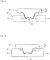
Fig. 9 is a front view showing a first bending step of a second embodiment; -
Fig. 10 is a front view showing a second bending step of the second embodiment; -
Fig. 11 is a front view showing a first bending step in a first modification of the second embodiment; -
Fig. 12 is a front view showing a second bending step in a second modification of the second embodiment; -
Fig. 13 is a front view showing a first bending step in the second modification of the second embodiment; and -
Fig. 14 is a front view showing a second bending step in the second modification of the second embodiment. - In the following, embodiments of the present invention will be described with reference to the accompanying drawings.
- A method for manufacturing a press-molded article according to the present embodiment is to press-mold a patchwork blank to obtain a press-molded article having a desired shape. The present method can be used specifically for forming the members that constitute the framework of an automobile (see
Fig. 1 ) . In the following, a method for manufacturing a B-pillar 100 (seeFig. 2 ) using the present method will be described. As will be described in detail below, this press molding is performed by first bending and second bending. - With reference to
Fig. 3 , thepress molding apparatus 10 is an apparatus for press-molding a plate-shaped patchwork blank 1 into a hat shape. The patchwork blank 1 is obtained by welding two pieces of plate-shaped patchwork 3 to a piece of plate-shaped basework 2 to form two thickenedportions 4. The patchwork blank 1 is made of mild steel or hot stamping material and has good bending workability. For example, the thickness of thebasework 2 is 1. 6 mm or 1.8 mm, and the thickness of thepatchwork 3 is 1.8 mm or 2.3 mm. - The
press molding apparatus 10 of the present embodiment includes a fixedbase 11, aslide plate 12 arranged above the fixedbase 11, adie 20, adrive mechanism 13, and acam mechanism 14. Thedie 20 includes alower die 21, afirst punch 22, and asecond punch 23. In addition, since the detailed configurations of thedrive mechanism 13 and thecam mechanism 14 are the same as those generally used for thepress molding apparatus 10, detailed description and illustration thereof will be omitted. - The fixed
base 11 is fixed and immovable. Thelower die 21 is attached to the fixedbase 11. Therefore, thelower die 21 is also fixed and immovable. - The
lower die 21 has a recessed shape. Thebottom surface 21a forming the recessed shape of thelower die 21 is a horizontal flat surface. The left and right bothcorner portions 21b of the bottom surface 2.1a are formed one step lower than the flat surface. Thus, when the patchwork blank 1 is molded into a hat shape, drawing for improving strength can be formed at the top portion 110 (seeFig. 8 ). In addition, the twoside surfaces 21c that rise to spread diagonally upward from bothcorner portions 21b are flat surfaces. - The
slide plate 12 is driven in the up-down direction (vertical direction) by thedrive mechanism 13, that is, can be raised and lowered (see arrows A1 and A2). In the present embodiment, thedrive mechanism 13 is hydraulic type or mechanical type (servo type) . Thedrive mechanism 13 can also stop the raising and lowering of theslide plate 12 and maintain the pressurized state. Afirst punch 22 is attached to theslide plate 12 so as to protrude downward. Therefore, thefirst punch 22 can also be raised and lowered. - The
first punch 22 has a protruding shape. The protruding-shapedtop portion 22a of thefirst punch 22 has a horizontal flat surface 22a1 and a protruding portion 22a2 protruding from the flat surface 22a1. The protruding portion 22a2 is provided in the center of thefirst punch 22 in the horizontal direction, and its width is large enough to be arranged between two pieces of thepatchwork 3. In addition, the height of the protruding portion 22a2 substantially corresponds to the thickness of thepatchwork 3. The left and right bothcorner portions 22b of thetop portion 22a protrude more downward than thetop portion 22a. Therefore, during press molding, bothcorner portions 22b are made to first come into contact with the patchwork blank 1. Theside surface 22c that rises to spread diagonally upward from bothcorner portions 22b is a flat surface with astep 22d. The height of thestep 22d roughly corresponds to the thickness of thepatchwork 3. Therefore, the surface of thefirst punch 22 is lowered one step from the protruding portion 22a2 to thestep 22d corresponding to the size of thepatchwork 3. In addition, during press molding, the position of thestep 22d corresponds to the position of the top portion of thelower die 21 in the vertical direction. Therefore, only the thickenedportion 4 can be sandwiched between thelower die 21 and thefirst punch 22. In addition, theside surface 22c of thefirst punch 22 is connected to theflange surface 22f via thecorner portion 22e. Theflange surface 22f is a flat surface extending outward in the horizontal direction. - The
second punch 23 is arranged below thefirst punch 22 and on the lateral side of thelower die 21. Thesecond punch 23 is mechanically connected to thecam mechanism 14 and is driven diagonally upward by thecam mechanism 14 toward the first punch 22 (see arrow A3). Thecam mechanism 14 converts the driving force in the vertical direction of the drive mechanism 13 (see arrows A1 and A2) into the driving force in the direction inclined from the vertical direction (see arrow A3). The direction inclined from the vertical direction (see arrow A3) is also the direction perpendicular to theside surface 22c of thefirst punch 22. - The
second punch 23 has an approximately L-shape in a front view, and twosecond punches 23 are arranged on both sides across thelower die 21. Thesecond punch 23 includes abase portion 23a extending in the vertical direction and atip portion 23b extending horizontally inward (toward the lower die 21) from the upper end portion of thebase portion 23a. Theside surface 23c of thetip portion 23b faces theside surface 22c of thefirst punch 22, and is formed substantially parallel to theside surface 22c of thefirst punch 22 and theside surface 21c of thelower die 21. Theupper surface 23d of thesecond punch 23 faces theflange surface 22f of thefirst punch 22 and is a flat surface extending in the horizontal direction. - In the present embodiment, the
lower die 21, thefirst punch 22, and thedrive mechanism 13 constitute the first mechanism of the present invention, and thefirst punch 22, thesecond punch 23, and thecam mechanism 14 constitute the second mechanism of the present invention. It is preferable that the first mechanism and the second mechanism are driven to be interlocked with each other. In the present embodiment, the first mechanism and the second mechanism are interlocked so that each step inFigs. 4 to 7 described below can be executed by one press of thepress molding apparatus 10. -
Figs. 4 to 7 show in order each step of the method for manufacturing a press-molded article according to the present embodiment. It should be noted that inFigs. 4 to 7 , only the patchwork blank 1 and the die 20 (lower die 21,first punch 22, and second punch 23) are shown for clarity of illustration. -
Fig. 4 shows the preparation step. In the preparation step, the patchwork blank 1 is set in thedie 20. At this time, the patchwork blank 1 is arranged with the surface to which thepatchwork 3 is welded facing up. With this arrangement, when the patchwork blank 1 is press-molded into a hat shape, thepatchwork 3 is arranged inside the hat shape, which does not spoil the aesthetic appearance. Thefirst punch 22 and thelower die 21 are arranged vertically spaced apart, and thesecond punch 23 is arranged on both sides of thelower die 21 in the horizontal direction. -
Figs. 5 and6 show the first bending step in which the first bending is performed.Fig. 5 shows before the first bending, andFig. 6 shows after the first bending. In the first bending step, only the thickenedportion 4 is bent. "Only the thickenedportion 4 is bent" means that only the thickenedportion 4 is sandwiched and bent by press molding, and the portion is formed into the shape of a press-molded article (B pillar 100). Therefore, the portion other than the thickenedportion 4 may be partially bent in association with the bending, but the bending does not have the shape of the press-molded article (B pillar 100), and the correction machining or the like is performed later (see the dashed circle inFig. 6 ). - In the first bending step, the
first punch 22 is lowered by the drive mechanism 13 (seeFig. 3 ), and bothcorner portions 22b of thefirst punch 22 come into contact with the thickenedportion 4 of the patchwork blank 1. Then, the thickenedportion 4 is sandwiched between bothcorner portions 21b of thelower die 21 and bothcorner portions 22b of thefirst punch 22, and the thickenedportion 4 of the patchwork blank 1 is bent. In the present step, a hat-shaped top portion 110 (seeFigs. 2 and8 ) is formed. -
Figs. 6 and 7 show the second bending step in which the second bending is performed.Fig. 6 shows before the second bending, andFig. 7 shows after the second bending. In the second bending step, the portion other than the thickenedportion 4 is bent. After the first bending, as shown inFig. 6 , only the thickenedportion 4 of the patchwork blank 1 is sandwiched between thefirst punch 22 and thelower die 21. In other words, the portion other than the thickened portion 4 (the hat-shapedbrim portion 120 described below) is not sandwiched. - In the second bending step, while maintaining the press pressure of the
first punch 22 and thelower die 21 from the state shown inFig. 6 , thesecond punch 23 receives force from the cam mechanism 14 (seeFig. 3 ), and is driven diagonally upward (see the arrow inFig. 7 ) . That is, thesecond punch 23 is brought close to the patchwork blank 1 from both the left and right sides, and the portion other than the thickenedportion 4 of the patchwork blank 1 is sandwiched between thefirst punch 22 and thesecond punch 23, and the portion other than the thickenedportion 4 is bent. Specifically, the patchwork blank 1 is sandwiched between theside surface 23c of thesecond punch 23 and theside surface 22c of thefirst punch 22, and the patchwork blank 1 is sandwiched between theupper surface 23d of thesecond punch 23 and theflange surface 22f of thefirst punch 22. In the present step, a hat-shaped brim portion 120 (seeFigs. 2 and8 ) is formed. - In this way, the hat-shaped B-
pillar 100 having the thickenedportion 4 as shown inFig. 8 can be manufactured. - According to the present embodiment, there are the following advantages.
- Since the steps of the bending are divided between the thickened
portion 4 and the other portion, it is possible to prevent stress from concentrating on the joint portion between thebasework 2 and thepatchwork 3 and to prevent unintended cracking or bending at the joint portion from occurring. Therefore, each portion can be bent accurately. Here, the term "different step" is assumed to be broadly construed, and refers to a step performed in multiple stages, excluding those performed at the same time. Therefore, the "different step" includes not only a step of performing bending to be divided into a plurality of presses but also a step of performing bending with multiple stages in one press. It should be noted that any one of the bending step of the thickenedportion 4 and the bending step of the portion other than the thickenedportion 4 may be executed first. - Since the mechanism for bending the thickened
portion 4 and the other portion is divided into the first mechanism and the second mechanism, each of the thickenedportion 4 and the other portion can be bent accurately. - With the first mechanism and the second mechanism, two press directions can be achieved with one
press molding apparatus 10. Therefore, a shape having a plurality of bent portions such as a hat shape can be accurately bent. Preferably, the first mechanism and the second mechanism are interlocked with each other to perform two-stage bending with one press of thepress molding apparatus 10. - Since a member having good bending workability such as mild steel or hot stamping material is used for the patchwork blank 1, it is possible to further prevent unintended cracking or bending. In addition, it may be necessary to reinforce a member having a relatively low strength such as mild steel or a hot stamping material by providing a thickened
portion 4. Therefore, it is effective to form the thickenedportion 4 for reinforcement and to prevent unintended cracking or bending by the above method to achieve accurate bending. - The B-pillar of an automobile requires a certain level of strength to protect the vehicle interior against a side collision. In addition, an accurate hat shape is required in consideration of assembling property. Therefore, using the method of the present embodiment makes it possible to manufacture a hat-shaped B-
pillar 100 having high strength and accuracy. - In the second embodiment shown in
Figs. 9 and 10 , two types of bendingpieces Fig. 3 ) of the first embodiment. In addition, the shape of thepatchwork 3 is different from that of the first embodiment. Those other than these are substantially the same as those of the first embodiment. Therefore, description of the same portions as of the first embodiment may be omitted. -
Fig. 9 shows the first bending step, andFig. 10 shows the second bending. - In the first bending step, the thickened
portion 4 is bent by using thefirst bending piece 30. Thefirst bending piece 30 has a shape corresponding to the shape of the thickenedportion 4. Thefirst bending piece 30 includes a first sidepart bending piece 31 arranged on the left and right sides of thefirst punch 22, and a first lowerpart bending piece 32 arranged between the first sidepart bending pieces 31. The first sidepart bending piece 31 is arranged to face the portion from thecorner portion 22b to thestep 22d of thefirst punch 22, and thepatchwork blank 1 of the portion is sandwiched together with thefirst punch 22 and bent. The first lowerpart bending piece 32 is arranged to face the portion from thecorner portion 22e to thetop portion 22a of thefirst punch 22, and thepatchwork blank 1 of the portion is sandwiched together with thefirst punch 22 and bent. - In the second bending step, a portion other than the thickened
portion 4 is bent by using thesecond bending piece 40. Thesecond bending piece 40 has a shape also corresponding to the shape of a portion other than the thickenedportion 4. Thesecond bending piece 40 includes a second sidepart bending piece 41 arranged on the left and right sides of thefirst punch 22, and a second lowerpart bending piece 42 arranged between the second sidepart bending pieces 41. The second sidepart bending piece 41 is arranged to face the portion from thecorner portion 22b to theflange surface 22f of thefirst punch 22, and thepatchwork blank 1 of the portion is sandwiched together with thefirst punch 22 and bent. The second lowerpart bending piece 42 is the same as the first lowerpart bending piece 32. - In order to perform the first bending step and the second bending step in one
press molding apparatus 10, two presses are performed. Specifically, after the first press is executed in the first bending step, thefirst bending piece 30 of thepress molding apparatus 10 is replaced with thesecond bending piece 40, and the second press is executed in the second bending step. - As in the first modification of the second embodiment shown in
Figs. 11 and 12 , thefirst bending piece 30 may be an integrated type. Similarly, thesecond bending piece 40 may also be an integrated type. The mode of bending is the same as described above. - As in the second modification of the second embodiment shown in
Figs. 13 and 14 , drawing machining (bending) may be performed in two stages. In the present modification, first, with reference toFig. 13 , shallow drawing machining is performed with thefirst bending piece 35 and theshallow drawing punch 24. Next, with reference toFig. 14 , deep drawing machining is performed with thesecond bending piece 45 and thedeep drawing punch 25. - The
shallow drawing punch 24 and thedeep drawing punch 25 have substantially the same shape as the first punch 22 (seeFig. 9 ) of the second embodiment described above. However, in the present modification, the patchwork blank 1 in which one piece of thepatchwork 3 is welded to thebasework 2 is drawn. Thepatchwork 3 is welded to thebasework 2 to cover the entire top portion 110 (seeFig. 8 ) when the patchwork blank 1 is formed in a hat shape. Corresponding to the shape of the patchwork blank 1, theshallow drawing punch 24 and thedeep drawing punch 25 of the present modification do not have the above-described protruding portion 22a2 (seeFig. 3 ). In addition, theshallow drawing punch 24 has a relatively smaller downward protrusion amount than thedeep drawing punch 25, and in the present modification, the protrusion amount is about half that of thedeep drawing punch 25. - The
first bending piece 35 has substantially the same shape as the first bending piece 30 (seeFig. 9 ) of the second embodiment described above. In addition, thesecond bending piece 45 also has substantially the same shape as the second bending piece 40 (seeFig. 9 ) of the second embodiment described above. - According to the present embodiment and its modification, the thickened
portion 4 can be bent with thefirst bending piece 30, and the portion other than the thickenedportion 4 can be bent with thesecond bending piece 40. Replacing these two bendingpieces press molding apparatus 10 having a simple structure. - As described above, although the specific embodiments and their modifications of the present invention are described, the present invention is not limited to the above-described embodiments, and can be implemented with various modifications within the scope of the present invention. For example, an appropriate combination of contents of the individual embodiments may be one embodiment of the present invention.
- In addition, the application target of the present invention is not limited to the above-described
B pillar 100. For example, the present invention can also be applied to door beams, rockers, and the like of vehicle framework members. - In addition, in each of the above embodiments, an example of bending the patchwork blank 1 in which one or two pieces of the
patchwork 3 are welded to thebasework 2 is described, but the number of pieces of thepatchwork 3 to be welded is not particularly limited, and may be three or more. The bending shape of the patchwork blank 1 is not limited to the hat shape, and the patchwork blank 1 can be bent into any shape. -
- 1
- Patchwork blank
- 2
- Basework
- 3
- Patchwork
- 4
- Thickened portion
- 10
- Press molding apparatus
- 11
- Fixed base
- 12
- Slide plate
- 13
- Drive mechanism (first mechanism)
- 14
- Cam mechanism (second mechanism)
- 20
- Die
- 21
- Lower die (first mechanism)
- 21a
- Bottom surface
- 21b
- Corner portion
- 21c
- Side surface
- 22
- First punch (first mechanism, second mechanism)
- 22a
- Top portion
- 22a1
- Flat surface
- 22a2
- Protruding portion
- 22b
- Corner portion
- 22c
- Side surface
- 22d
- Step
- 22e
- Corner portion
- 22f
- Flange surface
- 23
- Second punch (second mechanism)
- 23a
- Base portion
- 23b
- Tip portion
- 23c
- Side surface
- 23d
- Upper surface
- 24
- Shallow drawing punch (first mechanism)
- 25
- Deep drawing punch (second mechanism)
- 30, 35
- First bending piece (first mechanism)
- 31
- First side part bending piece
- 32
- First lower part bending piece
- 40, 45
- Second bending piece (second mechanism)
- 41
- Second side part bending piece
- 42
- Second lower part bending piece
- 100
- B pillar
- 110
- Top portion
- 120
- Brim portion
Claims (6)
- A method for manufacturing a press-molded article, the method comprising:preparing a patchwork blank in which a thickened portion is formed by welding patchwork to basework;bending only the thickened portion of the patchwork blank; andbending a portion other than the thickened portion in a step different from bending of the thickened portion.
- The method for manufacturing a press-molded article according to claim 1, further comprising bending the patchwork blank by using a press molding apparatus including a first mechanism configured to bend only the thickened portion and a second mechanism configured to bend a portion other than the thickened portion.
- The method for manufacturing a press-molded article according to claim 2, wherein
the first mechanism is driven in a vertical direction to apply a press load in a vertical direction to the thickened portion, and
the second mechanism includes a cam mechanism that converts a press load in a vertical direction of the first mechanism from a vertical direction to an inclined direction, and causes the cam mechanism to be driven in a direction inclined from a vertical direction to apply a press load in a direction inclined from a vertical direction to a portion other than the thickened portion. - The method for manufacturing a press-molded article according to claim 2, wherein
the first mechanism includes a first bending piece corresponding to a shape of the thickened portion, and
the second mechanism includes a second bending piece corresponding to a shape of a portion other than the thickened portion. - The method for manufacturing a press-molded article according to any one of claims 1 to 4, wherein the patchwork blank is made of mild steel or a hot stamping material.
- The method for manufacturing a press-molded article according to any one of claims 1 to 4, wherein the press-molded article is a B-pillar of an automobile and has a hat-shaped cross section.
Applications Claiming Priority (2)
| Application Number | Priority Date | Filing Date | Title |
|---|---|---|---|
| JP2018121198A JP6985989B2 (en) | 2018-06-26 | 2018-06-26 | Manufacturing method of press-molded products |
| PCT/JP2019/018848 WO2020003767A1 (en) | 2018-06-26 | 2019-05-13 | Method for manufacturing press-molded article |
Publications (3)
| Publication Number | Publication Date |
|---|---|
| EP3815807A1 true EP3815807A1 (en) | 2021-05-05 |
| EP3815807A4 EP3815807A4 (en) | 2022-03-16 |
| EP3815807B1 EP3815807B1 (en) | 2025-10-08 |
Family
ID=68986254
Family Applications (1)
| Application Number | Title | Priority Date | Filing Date |
|---|---|---|---|
| EP19824688.6A Active EP3815807B1 (en) | 2018-06-26 | 2019-05-13 | Method for manufacturing press-molded article |
Country Status (6)
| Country | Link |
|---|---|
| US (1) | US12011756B2 (en) |
| EP (1) | EP3815807B1 (en) |
| JP (1) | JP6985989B2 (en) |
| CN (1) | CN112313020B (en) |
| ES (1) | ES3055832T3 (en) |
| WO (1) | WO2020003767A1 (en) |
Families Citing this family (7)
| Publication number | Priority date | Publication date | Assignee | Title |
|---|---|---|---|---|
| JP7217717B2 (en) * | 2020-02-21 | 2023-02-03 | 豊田鉄工株式会社 | Vehicle pillar structure |
| CN119212808A (en) * | 2022-05-26 | 2024-12-27 | 日本制铁株式会社 | Hot pressing device, method for producing hot pressing molded product, and hot pressing molded product |
| JP7593385B2 (en) * | 2022-06-22 | 2024-12-03 | Jfeスチール株式会社 | Press molding method and manufacturing method of press molded product |
| KR102471975B1 (en) * | 2022-08-10 | 2022-11-29 | (주)썬텍솔루션 | the method of manufacturing insulating sheet |
| JP7750920B2 (en) * | 2023-10-24 | 2025-10-07 | フタバ産業株式会社 | Molded product manufacturing method |
| JP7736221B1 (en) * | 2024-03-27 | 2025-09-09 | Jfeスチール株式会社 | Method for forming overlapping members and overlapping members press-formed by the method |
| JPWO2026058818A1 (en) * | 2024-09-10 | 2026-03-19 |
Family Cites Families (14)
| Publication number | Priority date | Publication date | Assignee | Title |
|---|---|---|---|---|
| US5941110A (en) * | 1997-05-12 | 1999-08-24 | Northern University | Adaptive method and apparatus for forming tailor welded blanks |
| KR20020028233A (en) | 2000-10-09 | 2002-04-17 | 이계안 | Assembly pannel-molding method |
| JP2011083807A (en) * | 2009-10-16 | 2011-04-28 | Daihatsu Motor Co Ltd | Method for manufacturing component having hat-shaped cross section |
| DE102009052210B4 (en) * | 2009-11-06 | 2012-08-16 | Voestalpine Automotive Gmbh | Method for producing components with regions of different ductility |
| EP3219403B1 (en) * | 2014-11-12 | 2022-05-04 | Nippon Steel Corporation | Manufacturing method and manufacturing device for press-molded article |
| CN107000025B (en) * | 2014-12-10 | 2019-11-26 | 日本制铁株式会社 | The manufacturing method of blank, formed products, mold and blank |
| WO2016140287A1 (en) | 2015-03-03 | 2016-09-09 | 新日鐵住金株式会社 | Press-forming method and press-forming device |
| EP3372322B1 (en) * | 2015-12-08 | 2023-05-10 | Nippon Steel Corporation | Method for manufacturing press-molded article, press device, and press line |
| US10633031B2 (en) * | 2015-12-18 | 2020-04-28 | Autotech Engineering S.L. | B-pillar central beam and method for manufacturing |
| JP2017140636A (en) * | 2016-02-12 | 2017-08-17 | 株式会社豊田中央研究所 | Hot press forming method |
| JP6681239B2 (en) * | 2016-03-28 | 2020-04-15 | 日本製鉄株式会社 | Press molding method |
| CA3029512A1 (en) * | 2016-07-13 | 2018-01-18 | Nippon Steel & Sumitomo Metal Corporation | Hot-stamping formed article, structural member using the same, and manufacturing method of hot-stamping formed article |
| JP6340389B2 (en) * | 2016-07-19 | 2018-06-06 | 東亜工業株式会社 | Hot press device, hot press method, and automobile body part manufacturing method |
| DE102016013466A1 (en) | 2016-11-12 | 2017-05-11 | Daimler Ag | Body component for a motor vehicle and method for producing a body component |
-
2018
- 2018-06-26 JP JP2018121198A patent/JP6985989B2/en active Active
-
2019
- 2019-05-13 EP EP19824688.6A patent/EP3815807B1/en active Active
- 2019-05-13 US US17/053,423 patent/US12011756B2/en active Active
- 2019-05-13 ES ES19824688T patent/ES3055832T3/en active Active
- 2019-05-13 WO PCT/JP2019/018848 patent/WO2020003767A1/en not_active Ceased
- 2019-05-13 CN CN201980042895.6A patent/CN112313020B/en active Active
Also Published As
| Publication number | Publication date |
|---|---|
| JP2020001055A (en) | 2020-01-09 |
| ES3055832T3 (en) | 2026-02-16 |
| JP6985989B2 (en) | 2021-12-22 |
| EP3815807B1 (en) | 2025-10-08 |
| CN112313020B (en) | 2023-03-10 |
| US20210229156A1 (en) | 2021-07-29 |
| WO2020003767A1 (en) | 2020-01-02 |
| EP3815807A4 (en) | 2022-03-16 |
| US12011756B2 (en) | 2024-06-18 |
| CN112313020A (en) | 2021-02-02 |
Similar Documents
| Publication | Publication Date | Title |
|---|---|---|
| EP3815807B1 (en) | Method for manufacturing press-molded article | |
| KR102407168B1 (en) | The manufacturing method and manufacturing device of the press parts | |
| EP2351624B1 (en) | Method of manufacturing closed structural member, press-forming device, and closed structural member | |
| US10220427B2 (en) | Press-molding apparatus, press-molding method, and press-molded product | |
| KR101114645B1 (en) | Press Forming Article, and Manufacturing Method and Apparatus for the Same | |
| EP3501684B1 (en) | Automobile-body press-formed component and manufacturing method therefor | |
| US8490456B2 (en) | Draw die and method of manufacturing same | |
| US11020785B2 (en) | Method and apparatus for manufacturing press component | |
| KR102043343B1 (en) | Panel shaped article and its manufacturing method | |
| KR102064246B1 (en) | Press-forming method and press-forming device | |
| WO2013191256A1 (en) | Method and apparatus for producing press-moulded article | |
| US11534815B2 (en) | Press formed product, automobile structural member with the press formed product, and method for producing press formed product | |
| EP3031544A1 (en) | Press-molded product, method for producing press-molded product, and device for producing press-molded product | |
| WO2016171229A1 (en) | Method for producing press-molded product, press-molded product, and pressing device | |
| JP5515279B2 (en) | Press-molded product, press-molded product manufacturing method and manufacturing apparatus | |
| CN114430703A (en) | Method for manufacturing press-molded article, and press-molding device | |
| JP2006320941A (en) | Press method and press mold | |
| RU2624260C2 (en) | Obtained by pressing in the form products and its manufacturing method | |
| JP6094699B2 (en) | PRESS-MOLDED PRODUCTION METHOD, PRESS-MOLDED PRODUCT, AND PRESS DEVICE | |
| KR20200033528A (en) | Molding device for forming subway window frame | |
| WO2023127695A1 (en) | Press-forming apparatus and method for producing press-formed article | |
| JP7589120B2 (en) | Molding apparatus and molding method using said molding apparatus | |
| KR102364201B1 (en) | Rigidity improvement method for press-formed product, press-forming die, press-formed product, and method for producing press-formed product | |
| JP2022173890A (en) | Manufacturing method of vehicle press component | |
| JP7181506B2 (en) | press mold |
Legal Events
| Date | Code | Title | Description |
|---|---|---|---|
| STAA | Information on the status of an ep patent application or granted ep patent |
Free format text: STATUS: THE INTERNATIONAL PUBLICATION HAS BEEN MADE |
|
| PUAI | Public reference made under article 153(3) epc to a published international application that has entered the european phase |
Free format text: ORIGINAL CODE: 0009012 |
|
| STAA | Information on the status of an ep patent application or granted ep patent |
Free format text: STATUS: REQUEST FOR EXAMINATION WAS MADE |
|
| 17P | Request for examination filed |
Effective date: 20201112 |
|
| AK | Designated contracting states |
Kind code of ref document: A1 Designated state(s): AL AT BE BG CH CY CZ DE DK EE ES FI FR GB GR HR HU IE IS IT LI LT LU LV MC MK MT NL NO PL PT RO RS SE SI SK SM TR |
|
| DAV | Request for validation of the european patent (deleted) | ||
| DAX | Request for extension of the european patent (deleted) | ||
| A4 | Supplementary search report drawn up and despatched |
Effective date: 20220211 |
|
| RIC1 | Information provided on ipc code assigned before grant |
Ipc: B21D 53/88 20060101ALI20220207BHEP Ipc: B21D 35/00 20060101ALI20220207BHEP Ipc: B62D 25/04 20060101ALI20220207BHEP Ipc: B21D 37/08 20060101ALI20220207BHEP Ipc: B21D 22/06 20060101ALI20220207BHEP Ipc: B21D 5/01 20060101ALI20220207BHEP Ipc: B21D 22/20 20060101AFI20220207BHEP |
|
| GRAP | Despatch of communication of intention to grant a patent |
Free format text: ORIGINAL CODE: EPIDOSNIGR1 |
|
| STAA | Information on the status of an ep patent application or granted ep patent |
Free format text: STATUS: GRANT OF PATENT IS INTENDED |
|
| INTG | Intention to grant announced |
Effective date: 20250502 |
|
| GRAS | Grant fee paid |
Free format text: ORIGINAL CODE: EPIDOSNIGR3 |
|
| GRAA | (expected) grant |
Free format text: ORIGINAL CODE: 0009210 |
|
| STAA | Information on the status of an ep patent application or granted ep patent |
Free format text: STATUS: THE PATENT HAS BEEN GRANTED |
|
| AK | Designated contracting states |
Kind code of ref document: B1 Designated state(s): AL AT BE BG CH CY CZ DE DK EE ES FI FR GB GR HR HU IE IS IT LI LT LU LV MC MK MT NL NO PL PT RO RS SE SI SK SM TR |
|
| P01 | Opt-out of the competence of the unified patent court (upc) registered |
Free format text: CASE NUMBER: UPC_APP_5707_3815807/2025 Effective date: 20250903 |
|
| REG | Reference to a national code |
Ref country code: GB Ref legal event code: FG4D Ref country code: CH Ref legal event code: F10 Free format text: ST27 STATUS EVENT CODE: U-0-0-F10-F00 (AS PROVIDED BY THE NATIONAL OFFICE) Effective date: 20251008 |
|
| REG | Reference to a national code |
Ref country code: DE Ref legal event code: R096 Ref document number: 602019076687 Country of ref document: DE |
|
| REG | Reference to a national code |
Ref country code: IE Ref legal event code: FG4D |
|
| REG | Reference to a national code |
Ref country code: SE Ref legal event code: TRGR |
|
| REG | Reference to a national code |
Ref country code: SK Ref legal event code: T3 Ref document number: E 47489 Country of ref document: SK |
|
| REG | Reference to a national code |
Ref country code: NL Ref legal event code: MP Effective date: 20251008 |
|
| REG | Reference to a national code |
Ref country code: ES Ref legal event code: FG2A Ref document number: 3055832 Country of ref document: ES Kind code of ref document: T3 Effective date: 20260216 |
|
| PG25 | Lapsed in a contracting state [announced via postgrant information from national office to epo] |
Ref country code: NL Free format text: LAPSE BECAUSE OF FAILURE TO SUBMIT A TRANSLATION OF THE DESCRIPTION OR TO PAY THE FEE WITHIN THE PRESCRIBED TIME-LIMIT Effective date: 20251008 |
|
| PGFP | Annual fee paid to national office [announced via postgrant information from national office to epo] |
Ref country code: GB Payment date: 20260325 Year of fee payment: 8 |
|
| REG | Reference to a national code |
Ref country code: LT Ref legal event code: MG9D |
|
| PG25 | Lapsed in a contracting state [announced via postgrant information from national office to epo] |
Ref country code: NO Free format text: LAPSE BECAUSE OF FAILURE TO SUBMIT A TRANSLATION OF THE DESCRIPTION OR TO PAY THE FEE WITHIN THE PRESCRIBED TIME-LIMIT Effective date: 20260108 |
|
| PG25 | Lapsed in a contracting state [announced via postgrant information from national office to epo] |
Ref country code: FI Free format text: LAPSE BECAUSE OF FAILURE TO SUBMIT A TRANSLATION OF THE DESCRIPTION OR TO PAY THE FEE WITHIN THE PRESCRIBED TIME-LIMIT Effective date: 20251008 Ref country code: HR Free format text: LAPSE BECAUSE OF FAILURE TO SUBMIT A TRANSLATION OF THE DESCRIPTION OR TO PAY THE FEE WITHIN THE PRESCRIBED TIME-LIMIT Effective date: 20251008 |
|
| PG25 | Lapsed in a contracting state [announced via postgrant information from national office to epo] |
Ref country code: RS Free format text: LAPSE BECAUSE OF FAILURE TO SUBMIT A TRANSLATION OF THE DESCRIPTION OR TO PAY THE FEE WITHIN THE PRESCRIBED TIME-LIMIT Effective date: 20260108 |
|
| PG25 | Lapsed in a contracting state [announced via postgrant information from national office to epo] |
Ref country code: IS Free format text: LAPSE BECAUSE OF FAILURE TO SUBMIT A TRANSLATION OF THE DESCRIPTION OR TO PAY THE FEE WITHIN THE PRESCRIBED TIME-LIMIT Effective date: 20260208 |
|
| PG25 | Lapsed in a contracting state [announced via postgrant information from national office to epo] |
Ref country code: PT Free format text: LAPSE BECAUSE OF FAILURE TO SUBMIT A TRANSLATION OF THE DESCRIPTION OR TO PAY THE FEE WITHIN THE PRESCRIBED TIME-LIMIT Effective date: 20260209 |
|
| PG25 | Lapsed in a contracting state [announced via postgrant information from national office to epo] |
Ref country code: PL Free format text: LAPSE BECAUSE OF FAILURE TO SUBMIT A TRANSLATION OF THE DESCRIPTION OR TO PAY THE FEE WITHIN THE PRESCRIBED TIME-LIMIT Effective date: 20251008 |
|
| PG25 | Lapsed in a contracting state [announced via postgrant information from national office to epo] |
Ref country code: LV Free format text: LAPSE BECAUSE OF FAILURE TO SUBMIT A TRANSLATION OF THE DESCRIPTION OR TO PAY THE FEE WITHIN THE PRESCRIBED TIME-LIMIT Effective date: 20251008 |
|
| PGFP | Annual fee paid to national office [announced via postgrant information from national office to epo] |
Ref country code: SK Payment date: 20260323 Year of fee payment: 8 |
|
| PG25 | Lapsed in a contracting state [announced via postgrant information from national office to epo] |
Ref country code: BG Free format text: LAPSE BECAUSE OF FAILURE TO SUBMIT A TRANSLATION OF THE DESCRIPTION OR TO PAY THE FEE WITHIN THE PRESCRIBED TIME-LIMIT Effective date: 20251008 |
|
| PG25 | Lapsed in a contracting state [announced via postgrant information from national office to epo] |
Ref country code: LT Free format text: LAPSE BECAUSE OF FAILURE TO SUBMIT A TRANSLATION OF THE DESCRIPTION OR TO PAY THE FEE WITHIN THE PRESCRIBED TIME-LIMIT Effective date: 20251008 |
|
| PG25 | Lapsed in a contracting state [announced via postgrant information from national office to epo] |
Ref country code: SM Free format text: LAPSE BECAUSE OF FAILURE TO SUBMIT A TRANSLATION OF THE DESCRIPTION OR TO PAY THE FEE WITHIN THE PRESCRIBED TIME-LIMIT Effective date: 20251008 |
|
| PGFP | Annual fee paid to national office [announced via postgrant information from national office to epo] |
Ref country code: ES Payment date: 20260601 Year of fee payment: 8 |
|
| PG25 | Lapsed in a contracting state [announced via postgrant information from national office to epo] |
Ref country code: DK Free format text: LAPSE BECAUSE OF FAILURE TO SUBMIT A TRANSLATION OF THE DESCRIPTION OR TO PAY THE FEE WITHIN THE PRESCRIBED TIME-LIMIT Effective date: 20251008 |
|
| PG25 | Lapsed in a contracting state [announced via postgrant information from national office to epo] |
Ref country code: IT Free format text: LAPSE BECAUSE OF FAILURE TO SUBMIT A TRANSLATION OF THE DESCRIPTION OR TO PAY THE FEE WITHIN THE PRESCRIBED TIME-LIMIT Effective date: 20251008 |
|
| PGFP | Annual fee paid to national office [announced via postgrant information from national office to epo] |
Ref country code: DE Payment date: 20260527 Year of fee payment: 8 |
|
| PGFP | Annual fee paid to national office [announced via postgrant information from national office to epo] |
Ref country code: AT Payment date: 20260428 Year of fee payment: 8 Ref country code: SE Payment date: 20260421 Year of fee payment: 8 |
|
| PG25 | Lapsed in a contracting state [announced via postgrant information from national office to epo] |
Ref country code: EE Free format text: LAPSE BECAUSE OF FAILURE TO SUBMIT A TRANSLATION OF THE DESCRIPTION OR TO PAY THE FEE WITHIN THE PRESCRIBED TIME-LIMIT Effective date: 20251008 |
|
| PGFP | Annual fee paid to national office [announced via postgrant information from national office to epo] |
Ref country code: CZ Payment date: 20260505 Year of fee payment: 8 Ref country code: TR Payment date: 20260409 Year of fee payment: 8 |
|
| PGFP | Annual fee paid to national office [announced via postgrant information from national office to epo] |
Ref country code: FR Payment date: 20260527 Year of fee payment: 8 |
|
| PLBE | No opposition filed within time limit |
Free format text: ORIGINAL CODE: 0009261 |
|
| STAA | Information on the status of an ep patent application or granted ep patent |
Free format text: STATUS: NO OPPOSITION FILED WITHIN TIME LIMIT |