WO2020003767A1 - Method for manufacturing press-molded article - Google Patents
Method for manufacturing press-molded article Download PDFInfo
- Publication number
- WO2020003767A1 WO2020003767A1 PCT/JP2019/018848 JP2019018848W WO2020003767A1 WO 2020003767 A1 WO2020003767 A1 WO 2020003767A1 JP 2019018848 W JP2019018848 W JP 2019018848W WO 2020003767 A1 WO2020003767 A1 WO 2020003767A1
- Authority
- WO
- WIPO (PCT)
- Prior art keywords
- bending
- press
- punch
- thickened portion
- patchwork
- Prior art date
Links
Images


Classifications
-
- B—PERFORMING OPERATIONS; TRANSPORTING
- B21—MECHANICAL METAL-WORKING WITHOUT ESSENTIALLY REMOVING MATERIAL; PUNCHING METAL
- B21D—WORKING OR PROCESSING OF SHEET METAL OR METAL TUBES, RODS OR PROFILES WITHOUT ESSENTIALLY REMOVING MATERIAL; PUNCHING METAL
- B21D22/00—Shaping without cutting, by stamping, spinning, or deep-drawing
- B21D22/02—Stamping using rigid devices or tools
- B21D22/06—Stamping using rigid devices or tools having relatively-movable die parts
-
- B—PERFORMING OPERATIONS; TRANSPORTING
- B21—MECHANICAL METAL-WORKING WITHOUT ESSENTIALLY REMOVING MATERIAL; PUNCHING METAL
- B21D—WORKING OR PROCESSING OF SHEET METAL OR METAL TUBES, RODS OR PROFILES WITHOUT ESSENTIALLY REMOVING MATERIAL; PUNCHING METAL
- B21D37/00—Tools as parts of machines covered by this subclass
- B21D37/08—Dies with different parts for several steps in a process
-
- B—PERFORMING OPERATIONS; TRANSPORTING
- B21—MECHANICAL METAL-WORKING WITHOUT ESSENTIALLY REMOVING MATERIAL; PUNCHING METAL
- B21D—WORKING OR PROCESSING OF SHEET METAL OR METAL TUBES, RODS OR PROFILES WITHOUT ESSENTIALLY REMOVING MATERIAL; PUNCHING METAL
- B21D22/00—Shaping without cutting, by stamping, spinning, or deep-drawing
- B21D22/20—Deep-drawing
- B21D22/203—Deep-drawing of compound articles
-
- B—PERFORMING OPERATIONS; TRANSPORTING
- B21—MECHANICAL METAL-WORKING WITHOUT ESSENTIALLY REMOVING MATERIAL; PUNCHING METAL
- B21D—WORKING OR PROCESSING OF SHEET METAL OR METAL TUBES, RODS OR PROFILES WITHOUT ESSENTIALLY REMOVING MATERIAL; PUNCHING METAL
- B21D22/00—Shaping without cutting, by stamping, spinning, or deep-drawing
- B21D22/20—Deep-drawing
- B21D22/26—Deep-drawing for making peculiarly, e.g. irregularly, shaped articles
-
- B—PERFORMING OPERATIONS; TRANSPORTING
- B21—MECHANICAL METAL-WORKING WITHOUT ESSENTIALLY REMOVING MATERIAL; PUNCHING METAL
- B21D—WORKING OR PROCESSING OF SHEET METAL OR METAL TUBES, RODS OR PROFILES WITHOUT ESSENTIALLY REMOVING MATERIAL; PUNCHING METAL
- B21D24/00—Special deep-drawing arrangements in, or in connection with, presses
- B21D24/10—Devices controlling or operating blank holders independently, or in conjunction with dies
-
- B—PERFORMING OPERATIONS; TRANSPORTING
- B21—MECHANICAL METAL-WORKING WITHOUT ESSENTIALLY REMOVING MATERIAL; PUNCHING METAL
- B21D—WORKING OR PROCESSING OF SHEET METAL OR METAL TUBES, RODS OR PROFILES WITHOUT ESSENTIALLY REMOVING MATERIAL; PUNCHING METAL
- B21D35/00—Combined processes according to or processes combined with methods covered by groups B21D1/00 - B21D31/00
- B21D35/002—Processes combined with methods covered by groups B21D1/00 - B21D31/00
- B21D35/005—Processes combined with methods covered by groups B21D1/00 - B21D31/00 characterized by the material of the blank or the workpiece
- B21D35/007—Layered blanks
-
- B—PERFORMING OPERATIONS; TRANSPORTING
- B21—MECHANICAL METAL-WORKING WITHOUT ESSENTIALLY REMOVING MATERIAL; PUNCHING METAL
- B21D—WORKING OR PROCESSING OF SHEET METAL OR METAL TUBES, RODS OR PROFILES WITHOUT ESSENTIALLY REMOVING MATERIAL; PUNCHING METAL
- B21D5/00—Bending sheet metal along straight lines, e.g. to form simple curves
- B21D5/01—Bending sheet metal along straight lines, e.g. to form simple curves between rams and anvils or abutments
-
- B—PERFORMING OPERATIONS; TRANSPORTING
- B21—MECHANICAL METAL-WORKING WITHOUT ESSENTIALLY REMOVING MATERIAL; PUNCHING METAL
- B21D—WORKING OR PROCESSING OF SHEET METAL OR METAL TUBES, RODS OR PROFILES WITHOUT ESSENTIALLY REMOVING MATERIAL; PUNCHING METAL
- B21D53/00—Making other particular articles
- B21D53/88—Making other particular articles other parts for vehicles, e.g. cowlings, mudguards
-
- B—PERFORMING OPERATIONS; TRANSPORTING
- B62—LAND VEHICLES FOR TRAVELLING OTHERWISE THAN ON RAILS
- B62D—MOTOR VEHICLES; TRAILERS
- B62D25/00—Superstructure or monocoque structure sub-units; Parts or details thereof not otherwise provided for
- B62D25/04—Door pillars ; windshield pillars
Definitions
- the present invention relates to a method for producing a press-formed product.
- Patent Document 1 discloses a press forming technique in which a patchwork blank in which a thickened portion is formed by welding a plate-shaped patchwork to a plate-shaped basework is formed into a hat shape.
- the bending process is divided between the thickened portion and the other portion, it is possible to prevent stress from being concentrated on the joint portion between the base work and the patchwork, and unintended at the joint portion Cracking and bending can be prevented from occurring. Therefore, each part can be bent accurately.
- “different steps” are to be interpreted in a broad sense, and indicate steps performed in multiple steps, except steps performed simultaneously. Therefore, the “different process” includes not only a process in which bending is performed by pressing a plurality of times but also a process in which bending is performed in multiple stages by one press. Either of the step of bending the thickened portion and the step of bending the portion other than the thickened portion may be performed first.
- the term “bending” is a broad concept including drawing.
- the mechanism for bending the thickened portion and the other portion is divided into the first mechanism and the second mechanism, the thickened portion and the other portion are accurately bent. it can.
- two press directions can be realized by one press molding device by the first mechanism and the second mechanism. Therefore, a shape having a plurality of bent portions such as a hat shape can be accurately bent.
- the first mechanism and the second mechanism are interlocked, and perform two-stage bending with a single press of the press forming apparatus.
- the thickened portion can be bent by the first bending piece, and a portion other than the thickened portion can be bent by the second bending piece.
- the patchwork blank may be made of mild steel or hot stamped material.
- the press-formed product is a B pillar of an automobile, and the cross-sectional shape may be a hat shape.
- the method for manufacturing a press-formed product according to the present embodiment is to obtain a press-formed product having a desired shape by press-forming a patchwork blank.
- the method can be used, in particular, to form components that make up the framework of a motor vehicle (see FIG. 1).
- a method of manufacturing the B pillar 100 (see FIG. 2) using the present method will be described.
- the press forming is performed by a first bending process and a second bending process.
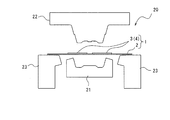
- the press forming apparatus 10 of the present embodiment includes a fixed base 11, a slide plate 12 disposed above the fixed base 11, a mold 20, a driving mechanism 13, and a cam mechanism 14.
- the mold 20 includes a die 21, a first punch 22, and a second punch 23. Since the detailed configurations of the drive mechanism 13 and the cam mechanism 14 are not different from those generally used in the press molding apparatus 10, detailed description and illustration are omitted.
- the fixed base 11 is fixed and immovable.
- a die 21 is attached to the fixed base 11. Therefore, the die 21 is also fixed and immovable.
- the die 21 has a concave shape.
- the bottom surface 21a forming the concave shape of the die 21 is a horizontal flat surface.
- Both left and right corners 21b of the bottom surface 21a are formed one step lower than the flat surface.
- the two side surfaces 21c that rise obliquely upward from the corners 21b are flat surfaces.
- the first punch 22 has a convex shape.
- the convex top 22a of the first punch 22 has a horizontal flat surface 22a1 and a protrusion 22a2 protruding from the flat surface 22a1.
- the protrusion 22a2 is provided at the center of the first punch 22 in the horizontal direction, and has a width that can be arranged between the two patchworks 3.
- the height of the protrusion 22a2 substantially corresponds to the thickness of the patchwork 3.
- Both left and right corners 22b of the top 22a project below the top 22a. Therefore, at the time of press molding, first, both corners 22 b are made to contact the patchwork blank 1.
- a side surface 22c that rises from both corners 22b and extends obliquely upward is a flat surface with a step 22d.
- the height of the step 22 d substantially corresponds to the thickness of the patchwork 3. Therefore, the surface of the first punch 22 is lowered by one step from the projection 22a2 to the step 22d in accordance with the size of the patchwork 3.
- the position of the step 22d and the position of the uppermost part of the die 21 correspond to each other in the vertical direction. Therefore, only the thickened portion 4 can be sandwiched between the die 21 and the first punch 22.
- the side surface 22c of the first punch 22 is connected to the flange surface 22f via a corner 22e.
- the flange surface 22f is a flat surface extending outward in the horizontal direction.
- a second punch 23 is disposed below the first punch 22 and beside the die 21.
- the second punch 23 is mechanically connected to the cam mechanism 14, and is driven obliquely upward by the cam mechanism 14 toward the first punch 22 (see arrow A3).
- the cam mechanism 14 converts a driving force in the vertical direction (see arrows A1 and A2) of the driving mechanism 13 into a driving force in a direction inclined from the vertical direction (see arrow A3).
- the direction inclined from the vertical direction (see the arrow A3) is also a direction perpendicular to the side surface 22c of the first punch 22.
- the second punch 23 has a substantially L-shape in a front view, and two second punches 23 are arranged on both sides of the die 21.
- the second punch 23 includes a base 23a extending in the vertical direction and a tip 23b extending inward in the horizontal direction (toward the die 21) from the upper end of the base 23a.
- the side surface 23c of the distal end portion 23b faces the side surface 22c of the first punch 22 and is formed substantially parallel to the side surface 22c of the first punch 22 and the side surface 21c of the die 21.
- the upper surface 23d of the second punch 23 is a flat surface that faces the flange surface 22f of the first punch 22 and extends in the horizontal direction.
- the die 21, the first punch 22, and the driving mechanism 13 constitute a first mechanism of the present invention
- the first punch 22, the second punch 23, and the cam mechanism 14 constitute a second mechanism of the present invention.
- the first mechanism and the second mechanism are driven in conjunction with each other.
- the first mechanism and the second mechanism are interlocked, and each step of FIGS. 4 to 7 described below can be executed by one press of the press molding apparatus 10.
- 4 to 7 sequentially show the steps of the method for manufacturing a press-formed product according to the present embodiment. 4 to 7, only the patchwork blank 1 and the mold 20 (die 21, first punch 22, and second punch 23) are shown for clarity.
- FIG. 4 shows a preparation process.
- the patchwork blank 1 is set in the mold 20.
- the patchwork blank 1 is arranged with the surface to which the patchwork 3 is welded facing upward.
- the first punch 22 and the die 21 are arranged at an interval in the vertical direction, and the second punches 23 are arranged on both sides of the die 21 in the horizontal direction.
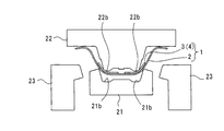
- FIGS. 5 and 6 show a first bending step of performing the first bending process.
- FIG. 5 shows a state before the first bending
- FIG. 6 shows a state after the first bending.
- “Bending only the thickened portion 4” means that only the thickened portion 4 is sandwiched by press forming and bent to form the portion into the shape of a press-formed product (B pillar 100). Accordingly, a portion other than the thickened portion 4 may be partially bent in association with the bending process. However, the bending is not performed in the shape of the press-formed product (the B pillar 100), but is corrected later. (See the broken circle in FIG. 6).
- the first punch 22 is lowered by the drive mechanism 13 (see FIG. 3), and the corners 22b of the first punch 22 come into contact with the thickened portion 4 of the patchwork blank 1. Then, the thickened portion 4 is sandwiched between both corners 21b of the die 21 and both corners 22b of the first punch 22, and the thickened portion 4 of the patchwork blank 1 is bent. In this step, the hat-shaped top 110 (see FIGS. 2 and 8) is formed.
- the second punch 23 receives a force from the cam mechanism 14 (see FIG. 3) while maintaining the pressing pressure of the first punch 22 and the die 21 from the state of FIG. (See arrow). That is, the second punch 23 is brought closer to the patchwork blank 1 from both left and right sides, the first punch 22 and the second punch 23 sandwich the portion other than the thickened portion 4 of the patchwork blank 1, and the portions other than the thickened portion 4 To bend. More specifically, the patchwork blank 1 is sandwiched between the side surface 23c of the second punch 23 and the side surface 22c of the first punch 22, and the patchwork blank 1 is sandwiched between the upper surface 23d of the second punch 23 and the flange surface 22f of the first punch 22. Insert 1. By this step, the hat-shaped flange 120 (see FIGS. 2 and 8) is formed.
- the hat-shaped B pillar 100 having the thickened portion 4 as shown in FIG. 8 can be manufactured.
- the bending process is separated between the thickened portion 4 and the other portions, it is possible to prevent stress from being concentrated on the joint between the base work 2 and the patchwork 3, and to cause unintended cracking or bending at the joint. Can be prevented from occurring. Therefore, each part can be bent accurately.
- “different steps” are to be interpreted in a broad sense, and indicate steps performed in multiple steps, except steps performed simultaneously. Therefore, the “different process” includes not only a process in which bending is performed by pressing a plurality of times but also a process in which bending is performed in multiple stages by one press. Either the step of bending the thickened portion 4 or the step of bending the portion other than the thickened portion 4 may be performed first.
- Two press directions can be realized by one press forming apparatus 10 by the first mechanism and the second mechanism. Therefore, a shape having a plurality of bent portions such as a hat shape can be accurately bent.
- the first mechanism and the second mechanism are interlocked, and perform two-stage bending with a single press of the press forming apparatus 10.
- the B pillar of a car needs a certain strength to protect the cabin against side collision.
- an accurate hat shape is required in consideration of assemblability. Therefore, by using the method of the present embodiment, a high-strength and accurate hat-shaped B pillar 100 can be manufactured.
- FIG. 9 shows the first bending process
- FIG. 10 shows the second bending process
- the thickened portion 4 is bent using the first bending piece 30.
- the first bending piece 30 has a shape corresponding to the shape of the thickened portion 4.
- the first bending piece 30 includes a first side bending piece 31 disposed on the left and right of the first punch 22 and a first lower bending piece 32 disposed between the first side bending pieces 31.
- the first side bending piece 31 is arranged to face a portion from the corner 22b to the step 22d of the first punch 22.
- the first side bending piece 31 is bent by sandwiching the patchwork blank 1 of the portion together with the first punch 22.
- the first lower bending piece 32 is disposed so as to face a portion from the corner 22 e to the top 22 a of the first punch 22, and bends the patchwork blank 1 in that portion together with the first punch 22.
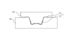
- the second bending piece 40 has a shape corresponding to the shape of the portion other than the thickened portion 4.
- the second bending piece 40 includes a second side bending piece 41 disposed on the left and right of the first punch 22 and a second lower bending piece 42 disposed between the second side bending pieces 41.
- the second side bending piece 41 is disposed so as to face a portion from the corner 22b of the first punch 22 to the flange surface 22f, and the patchwork blank 1 in the portion is sandwiched together with the first punch 22 and bent.
- the second lower bending piece 42 is the same as the first lower bending piece 32.
- the first bending piece 30 may be of an integral type.
- the second bending piece 40 may be an integral type.
- the mode of bending is the same as described above.
- drawing may be performed in two stages.
- shallow drawing is performed by the first bending piece 35 and the shallow drawing punch 24.
- deep drawing is performed by the second bending piece 45 and the deep drawing punch 25.
- the shallow-drawing punch 24 and the deep-drawing punch 25 have substantially the same shape as the first punch 22 of the second embodiment (see FIG. 9).
- the patchwork blank 1 in which one patchwork 3 is welded to the basework 2 is drawn.
- the patchwork 3 is welded to the basework 2 so as to cover the entire top 110 (see FIG. 8) when the patchwork blank 1 is formed in a hat shape.
- the shallow-drawing punch 24 and the deep-drawing punch 25 of the present modified example do not have the above-described protrusion 22a2 (see FIG. 3).
- the shallow-drawing punch 24 has a relatively smaller amount of protrusion downward than the deep-drawing punch 25, and in this modification, the protrusion amount is about half that of the deep-drawing punch 25.
- the first bending piece 35 has substantially the same shape as the first bending piece 30 (see FIG. 9) of the second embodiment.
- the second bending piece 45 has substantially the same shape as the second bending piece 40 (see FIG. 9) of the second embodiment described above.
- the thickened portion 4 can be bent by the first bending piece 30 and a portion other than the thickened portion 4 can be bent by the second bending piece 40.
- the application target of the present invention is not limited to the B pillar 100 described above.
- the present invention is also applicable to a door beam, a locker, and the like of a vehicle frame member.
- the example in which the patchwork blank 1 in which one or two patchworks 3 are welded to the base work 2 is bent is described, but the number of the patchwork 3 to be welded is not particularly limited. Or three or more.
- the bending shape of the patchwork blank 1 is not limited to the hat shape, and the patchwork blank 1 can be bent into an arbitrary shape.
Abstract
A method for manufacturing a press-molded article wherein a patchwork blank 1, in which a patchwork 3 is welded to a base workpiece 2 to form a thick portion 4, is prepared, only the thick portion 4 of the patchwork blank 1 is bent, and portions other than the thick portion 4 are bent in a different step than the step in which the thick portion 4 is bent.
Description
本発明は、プレス成形品の製造方法に関する。
The present invention relates to a method for producing a press-formed product.
自動車の骨格部材を金属板のプレス成形により製造する技術が知られている。当該技術分野では、様々な強度設計に対応すべく、板厚が一定の金属板だけでなく増厚部を有する金属板をプレス成形することが求められている。
技術 A technique for manufacturing a frame member of an automobile by press molding a metal plate is known. In the technical field, in order to cope with various strength designs, not only a metal plate having a constant thickness but also a metal plate having a thickened portion is required to be press-formed.
例えば、特許文献1には、板状のベースワークに板状のパッチワークを溶接して増厚部を形成したパッチワークブランクをハット形にプレス成形するプレス成形技術が開示されている。
For example, Patent Document 1 discloses a press forming technique in which a patchwork blank in which a thickened portion is formed by welding a plate-shaped patchwork to a plate-shaped basework is formed into a hat shape.
特許文献1に開示されたプレス成形技術では、ベースワークとパッチワークの接合部に曲げ応力が集中し、当該接合部において意図しない割れや折れ曲がりが生じるおそれがある。
According to the press forming technique disclosed in Patent Document 1, bending stress concentrates on a joint between the base work and the patchwork, and there is a possibility that an unintended crack or bend may occur at the joint.
本発明は、プレス成形品を製造する方法において、増厚部を有するパッチワークブランクのプレス成形の際の意図しない割れや折れ曲がりを防止することを課題とする。
An object of the present invention is to prevent unintended cracking or bending during press forming of a patchwork blank having a thickened portion in a method of manufacturing a press-formed product.
本発明の第1の態様は、ベースワークにパッチワークを溶接して増厚部を形成したパッチワークブランクを準備し、前記パッチワークブランクの前記増厚部のみを曲げ加工し、前記増厚部の曲げ加工とは異なる工程で前記増厚部以外の部分を曲げ加工することを含む、プレス成形品の製造方法を備えるプレス成形品の製造方法を提供する。
According to a first aspect of the present invention, a patchwork blank in which a thickened portion is formed by welding a patchwork to a basework is prepared, and only the thickened portion of the patchwork blank is bent to form the thickened portion. And a method for manufacturing a press-formed product including a method for manufacturing a press-formed product, the method including bending a portion other than the thickened portion in a step different from the bending process.
この方法によれば、増厚部とそれ以外の部分とで曲げ加工の工程を分けているため、ベースワークとパッチワークの接合部に応力が集中することを防止でき、当該接合部において意図しない割れや折れ曲がりが発生することを防止できる。従って、それぞれの部分を正確に曲げ加工できる。ここで、「異なる工程」とは広義に解釈されるものであり、同時に行われるものを除き、多段階で行われるものを示す。従って、「異なる工程」には、複数回のプレスに分けて曲げ加工を行うものだけでなく、1回のプレスで多段階で曲げ加工を行うものを含む。なお、増厚部の曲げ加工の工程と、増厚部以外の部分の曲げ加工の工程とは、いずれが先に実行されてもよい。また、ここでの「曲げ加工」とは、絞り加工を含む広義の概念である。
According to this method, since the bending process is divided between the thickened portion and the other portion, it is possible to prevent stress from being concentrated on the joint portion between the base work and the patchwork, and unintended at the joint portion Cracking and bending can be prevented from occurring. Therefore, each part can be bent accurately. Here, “different steps” are to be interpreted in a broad sense, and indicate steps performed in multiple steps, except steps performed simultaneously. Therefore, the “different process” includes not only a process in which bending is performed by pressing a plurality of times but also a process in which bending is performed in multiple stages by one press. Either of the step of bending the thickened portion and the step of bending the portion other than the thickened portion may be performed first. The term “bending” is a broad concept including drawing.
前記増厚部のみを曲げ加工する第1機構と、前記増厚部以外の部分を曲げ加工する第2機構とを備えるプレス成形装置を使用して前記パッチワークブランクの曲げ加工を行ってもよい。
The patchwork blank may be bent using a press forming apparatus including a first mechanism that bends only the thickened portion and a second mechanism that bends a portion other than the thickened portion. .
この方法によれば、増厚部とそれ以外の部分とを曲げ加工する機構を第1機構と第2機構とに分けているため、増厚部とそれ以外の部分とをそれぞれ正確に曲げ加工できる。
According to this method, since the mechanism for bending the thickened portion and the other portion is divided into the first mechanism and the second mechanism, the thickened portion and the other portion are accurately bent. it can.
前記第1機構は、鉛直方向に駆動して前記増厚部に鉛直方向のプレス荷重を加え、前記第2機構は、前記第1機構の鉛直方向のプレス荷重を鉛直方向から傾斜した方向に変換するカム機構を有し、前記カム機構によって鉛直方向から傾斜した方向に駆動して前記増厚部以外の部分に鉛直方向から傾斜した方向のプレス荷重を加えてもよい。
The first mechanism drives in the vertical direction to apply a vertical press load to the thickened portion, and the second mechanism converts the vertical press load of the first mechanism into a direction inclined from the vertical direction. A cam mechanism that drives in a direction inclined from the vertical direction by the cam mechanism to apply a press load in a direction inclined from the vertical direction to a portion other than the thickened portion.
この方法によれば、第1機構と第2機構とによって1つのプレス成形装置で2つのプレス方向を実現できる。従って、ハット形状のような複数の曲げ部を有する形状を正確に曲げ加工できる。好ましくは、第1機構と第2機構は連動し、プレス成形装置の1回のプレスで2段階の曲げ加工を行う。
According to this method, two press directions can be realized by one press molding device by the first mechanism and the second mechanism. Therefore, a shape having a plurality of bent portions such as a hat shape can be accurately bent. Preferably, the first mechanism and the second mechanism are interlocked, and perform two-stage bending with a single press of the press forming apparatus.
前記第1機構は、前記増厚部の形状に対応した第1曲げ駒を有し、前記第2機構は、前記増厚部以外の部分の形状に対応した第2曲げ駒を有してもよい。
The first mechanism may have a first bending piece corresponding to the shape of the thickened portion, and the second mechanism may have a second bending piece corresponding to the shape of a portion other than the thickened portion. Good.
この方法によれば、第1曲げ駒によって増厚部を曲げ加工できるともに、第2曲げ駒によって増厚部以外の部分を曲げ加工できる。これらの2つの曲げ駒を付け替えて使用することで、簡易な構成の1つのプレス成形装置で2つの工程の曲げ加工を実現できる。
According to this method, the thickened portion can be bent by the first bending piece, and a portion other than the thickened portion can be bent by the second bending piece. By replacing these two bending pieces and using them, it is possible to realize bending in two steps with one press forming apparatus having a simple configuration.
前記パッチワークブランクは、軟鋼ないしホットスタンプ材からなってもよい。
パ ッ チ The patchwork blank may be made of mild steel or hot stamped material.
この方法によれば、軟鋼ないしホットスタンプ材のように曲げ加工性が良好な部材をパッチワークブランクに使用することで、意図しない割れや折れ曲がりを一層防止できる。また、軟鋼ないしホットスタンプ材のような強度が比較的に低い部材には、増厚部を設けるなどして補強することが必要となることがある。従って、増厚部を形成して補強するとともに、上記方法によって意図しない割れや折れ曲がりを防止して正確な曲げ加工を実現できることは有効である。
According to this method, unintended cracking and bending can be further prevented by using a member having good bending workability such as a mild steel or a hot stamp material for the patchwork blank. In addition, a member having relatively low strength such as mild steel or a hot stamp material may need to be reinforced by providing a thickened portion or the like. Therefore, it is effective that the thickened portion is formed to reinforce and that the above-described method can prevent an unintended crack or bend to realize accurate bending.
前記プレス成形品は自動車のBピラーであり、断面形状がハット形であってもよい。
The press-formed product is a B pillar of an automobile, and the cross-sectional shape may be a hat shape.
この方法によれば、Bピラーを好適に製造できる。自動車のBピラーは、側面衝突に対して車室内を保護するために一定の強度を要する。また、組み立て性を考慮して正確なハット形が求められる。従って、上記方法を使用することで、高強度であるとともに正確なハット形のBピラーを製造できる。
B According to this method, the B pillar can be suitably manufactured. The B pillar of an automobile needs a certain strength in order to protect the cabin against side collision. In addition, an accurate hat shape is required in consideration of assemblability. Therefore, by using the above method, a high-strength and accurate hat-shaped B pillar can be manufactured.
本発明によれば、プレス成形品を製造する方法において、増厚部とそれ以外の部分とで曲げ加工の工程を分けているため、パッチワークブランクのプレス成形の際の意図しない割れや折れ曲がりを防止できる。
According to the present invention, in the method of manufacturing a press-formed product, since the bending process is divided into the thickened portion and the other portion, unintended cracking or bending during press-forming of the patchwork blank is performed. Can be prevented.
以下、添付図面を参照して本発明の実施形態を説明する。
Hereinafter, embodiments of the present invention will be described with reference to the accompanying drawings.
(第1実施形態)
本実施形態に係るプレス成形品の製造方法は、パッチワークブランクをプレス成形して所望の形状のプレス成形品を得るものである。本方法は、特に自動車の骨格(図1参照)を構成する部材を形成するために使用されることができる。以下では、本方法を使用してBピラー100(図2参照)を製造する方法について説明する。後に詳述するように、このプレス成形は、第1の曲げ加工と第2の曲げ加工とにより実行される。 (1st Embodiment)
The method for manufacturing a press-formed product according to the present embodiment is to obtain a press-formed product having a desired shape by press-forming a patchwork blank. The method can be used, in particular, to form components that make up the framework of a motor vehicle (see FIG. 1). Hereinafter, a method of manufacturing the B pillar 100 (see FIG. 2) using the present method will be described. As described later in detail, the press forming is performed by a first bending process and a second bending process.
図3を参照して、プレス成形装置10は、板状のパッチワークブランク1をハット形にプレス成形する装置である。パッチワークブランク1は、板状のベースワーク2に2枚の板状のパッチワーク3を溶接して2つの増厚部4を形成したものである。パッチワークブランク1は、軟鋼ないしホットスタンプ材からなり、良好な曲げ加工性を有している。例えば、ベースワーク2の厚みは1.6mmまたは1.8mmであり、パッチワーク3の厚みは1.8mmまたは2.3mmである。
参照 Referring to FIG. 3, press forming apparatus 10 is an apparatus for press-forming plate-shaped patchwork blank 1 into a hat shape. The patchwork blank 1 is formed by welding two plate-like patchworks 3 to a plate-like basework 2 to form two thickened portions 4. The patchwork blank 1 is made of a mild steel or a hot stamped material and has good bending workability. For example, the thickness of the base work 2 is 1.6 mm or 1.8 mm, and the thickness of the patch work 3 is 1.8 mm or 2.3 mm.
本実施形態のプレス成形装置10は、固定台11と、固定台11の上方に配置されたスライドプレート12と、金型20と、駆動機構13と、カム機構14とを備える。金型20は、ダイ21と、第1パンチ22と、第2パンチ23とを備える。また、駆動機構13とカム機構14の詳細な構成はプレス成形装置10に一般に使用されるものと相違ないため、詳細な説明および図示は省略する。
The press forming apparatus 10 of the present embodiment includes a fixed base 11, a slide plate 12 disposed above the fixed base 11, a mold 20, a driving mechanism 13, and a cam mechanism 14. The mold 20 includes a die 21, a first punch 22, and a second punch 23. Since the detailed configurations of the drive mechanism 13 and the cam mechanism 14 are not different from those generally used in the press molding apparatus 10, detailed description and illustration are omitted.
固定台11は、固定されており不動である。固定台11にはダイ21が取り付けられている。従って、ダイ21も、固定されており不動である。
The fixed base 11 is fixed and immovable. A die 21 is attached to the fixed base 11. Therefore, the die 21 is also fixed and immovable.
ダイ21は、凹形状を有している。ダイ21の凹形状を構成する底面21aは、水平な平坦面となっている。底面21aの左右の両角部21bは、平坦面よりも一段下げて形成されている。これにより、パッチワークブランク1をハット形に成形した際に頂部110(図8参照)に強度向上のための絞りを形成できる。また、両角部21bから斜め上方に広がって立ち上がる2つの側面21cは、平坦面となっている。
The die 21 has a concave shape. The bottom surface 21a forming the concave shape of the die 21 is a horizontal flat surface. Both left and right corners 21b of the bottom surface 21a are formed one step lower than the flat surface. Thereby, when the patchwork blank 1 is formed into a hat shape, a diaphragm for improving the strength can be formed at the top 110 (see FIG. 8). The two side surfaces 21c that rise obliquely upward from the corners 21b are flat surfaces.
スライドプレート12は、駆動機構13によって上下方向(鉛直方向)に駆動され、即ち昇降可能である(矢印A1,A2参照)。本実施形態では、駆動機構13は、油圧式または機械式(サーボ式)である。駆動機構13は、スライドプレート12の昇降を停止させ、加圧状態を保持することもできる。スライドプレート12には、下向きに突出するように第1パンチ22が取り付けられている。従って、第1パンチ22も昇降可能である。
The slide plate 12 is driven in the vertical direction (vertical direction) by the drive mechanism 13, that is, can be moved up and down (see arrows A1 and A2). In the present embodiment, the drive mechanism 13 is a hydraulic type or a mechanical type (servo type). The drive mechanism 13 can also stop the elevation of the slide plate 12 and maintain the pressurized state. A first punch 22 is attached to the slide plate 12 so as to protrude downward. Therefore, the first punch 22 can also be moved up and down.
第1パンチ22は、凸形状を有している。第1パンチ22の凸形状の頂部22aは、水平な平坦面22a1と、平坦面22a1から突出した突部22a2とを有している。突部22a2は水平方向において第1パンチ22の中央に設けられ、その幅は2枚のパッチワーク3の間に配置可能な大きさである。また、突部22a2の高さは、パッチワーク3の厚みに概ね対応している。頂部22aの左右の両角部22bは、頂部22aよりも下方へ突出している。従って、プレス成形の際には、最初に両角部22bがパッチワークブランク1に接触するようにされている。両角部22bから斜め上方に広がって立ち上がる側面22cは、段差22dのある平坦面となっている。段差22dの高さは、パッチワーク3の厚みに概ね対応している。従って、第1パンチ22の表面は、パッチワーク3の大きさに対応して突部22a2から段差22dにかけて一段下げられている。また、プレス成形の際には、鉛直方向において、段差22dの位置とダイ21の最上部の位置は対応する。従って、ダイ21と第1パンチ22とによって、増厚部4のみを挟み込むことができる。また、第1パンチ22の側面22cは、角部22eを介してフランジ面22fに接続されている。フランジ面22fは、水平方向外側に延びる平坦面となっている。
The first punch 22 has a convex shape. The convex top 22a of the first punch 22 has a horizontal flat surface 22a1 and a protrusion 22a2 protruding from the flat surface 22a1. The protrusion 22a2 is provided at the center of the first punch 22 in the horizontal direction, and has a width that can be arranged between the two patchworks 3. The height of the protrusion 22a2 substantially corresponds to the thickness of the patchwork 3. Both left and right corners 22b of the top 22a project below the top 22a. Therefore, at the time of press molding, first, both corners 22 b are made to contact the patchwork blank 1. A side surface 22c that rises from both corners 22b and extends obliquely upward is a flat surface with a step 22d. The height of the step 22 d substantially corresponds to the thickness of the patchwork 3. Therefore, the surface of the first punch 22 is lowered by one step from the projection 22a2 to the step 22d in accordance with the size of the patchwork 3. In press molding, the position of the step 22d and the position of the uppermost part of the die 21 correspond to each other in the vertical direction. Therefore, only the thickened portion 4 can be sandwiched between the die 21 and the first punch 22. The side surface 22c of the first punch 22 is connected to the flange surface 22f via a corner 22e. The flange surface 22f is a flat surface extending outward in the horizontal direction.
第1パンチ22の下方であって、ダイ21の側方には、第2パンチ23が配置されている。第2パンチ23は、カム機構14と機械的に接続されており、カム機構14によって斜め上方に第1パンチ22に向かって駆動される(矢印A3参照)。カム機構14は、駆動機構13の鉛直方向(矢印A1,A2参照)の駆動力を鉛直方向から傾斜した方向(矢印A3参照)の駆動力に変換するものである。鉛直方向から傾斜した方向(矢印A3参照)は、第1パンチ22の側面22cに垂直な方向でもある。
第 A second punch 23 is disposed below the first punch 22 and beside the die 21. The second punch 23 is mechanically connected to the cam mechanism 14, and is driven obliquely upward by the cam mechanism 14 toward the first punch 22 (see arrow A3). The cam mechanism 14 converts a driving force in the vertical direction (see arrows A1 and A2) of the driving mechanism 13 into a driving force in a direction inclined from the vertical direction (see arrow A3). The direction inclined from the vertical direction (see the arrow A3) is also a direction perpendicular to the side surface 22c of the first punch 22.
第2パンチ23は正面視において概ねL字型を有し、2つの第2パンチ23がダイ21を挟んで両側に配置されている。第2パンチ23は、鉛直方向に延びる基部23aと、基部23aの上端部から水平方向内側(ダイ21に向かう側)に延びる先端部23bとを備える。先端部23bの側面23cは、第1パンチ22の側面22cと対向し、第1パンチ22の側面22cおよびダイ21の側面21cと概ね平行に形成されている。第2パンチ23の上面23dは、第1パンチ22のフランジ面22fと対向し、水平方向に延びる平坦面となっている。
The second punch 23 has a substantially L-shape in a front view, and two second punches 23 are arranged on both sides of the die 21. The second punch 23 includes a base 23a extending in the vertical direction and a tip 23b extending inward in the horizontal direction (toward the die 21) from the upper end of the base 23a. The side surface 23c of the distal end portion 23b faces the side surface 22c of the first punch 22 and is formed substantially parallel to the side surface 22c of the first punch 22 and the side surface 21c of the die 21. The upper surface 23d of the second punch 23 is a flat surface that faces the flange surface 22f of the first punch 22 and extends in the horizontal direction.
本実施形態では、ダイ21と第1パンチ22と駆動機構13とが本発明の第1機構を構成し、第1パンチ22と第2パンチ23とカム機構14とが本発明の第2機構を構成する。第1機構と第2機構は、連動して駆動することが好ましい。本実施形態では、第1機構と第2機構が連動し、後述する図4~7の各工程をプレス成形装置10の1回のプレスで実行できるようにされている。
In the present embodiment, the die 21, the first punch 22, and the driving mechanism 13 constitute a first mechanism of the present invention, and the first punch 22, the second punch 23, and the cam mechanism 14 constitute a second mechanism of the present invention. Constitute. It is preferable that the first mechanism and the second mechanism are driven in conjunction with each other. In the present embodiment, the first mechanism and the second mechanism are interlocked, and each step of FIGS. 4 to 7 described below can be executed by one press of the press molding apparatus 10.
図4~7は、本実施形態に係るプレス成形品の製造方法の各工程を順に示している。なお、図4~7では、図示を明瞭にするため、パッチワークブランク1と金型20(ダイ21、第1パンチ22、および第2パンチ23)のみが示されている。
4 to 7 sequentially show the steps of the method for manufacturing a press-formed product according to the present embodiment. 4 to 7, only the patchwork blank 1 and the mold 20 (die 21, first punch 22, and second punch 23) are shown for clarity.
図4は、準備工程を示している。準備工程では、パッチワークブランク1を金型20にセットする。このとき、パッチワークブランク1は、パッチワーク3が溶接された面を上側にして配置される。このように配置すると、パッチワークブランク1がハット形にプレス成形された際にハット形の内側にパッチワーク3が配置されることになり、美観を損ねない。第1パンチ22とダイ21は鉛直方向に間隔を空けて配置され、第2パンチ23はダイ21の水平方向の両側に配置される。
FIG. 4 shows a preparation process. In the preparation step, the patchwork blank 1 is set in the mold 20. At this time, the patchwork blank 1 is arranged with the surface to which the patchwork 3 is welded facing upward. With this arrangement, when the patchwork blank 1 is press-formed into a hat shape, the patchwork 3 is arranged inside the hat shape, and the appearance is not spoiled. The first punch 22 and the die 21 are arranged at an interval in the vertical direction, and the second punches 23 are arranged on both sides of the die 21 in the horizontal direction.
図5,6は、第1の曲げ加工を実行する第1曲げ工程を示している。図5は第1の曲げ加工前を示しており、図6は第1の曲げ加工後を示している。第1曲げ工程では、増厚部4のみを曲げ加工する。「増厚部4のみを曲げ加工する」とは、プレス成形によって増厚部4のみを挟み込んで曲げ加工し、当該部分をプレス成形品(Bピラー100)の形とすることをいう。従って、当該曲げ加工に付随して増厚部4以外の部分が部分的に曲げられることもあるが、当該曲げはプレス成形品(Bピラー100)の形状とするものではなく、後に修正加工等されるものである(図6の破線円参照)。
FIGS. 5 and 6 show a first bending step of performing the first bending process. FIG. 5 shows a state before the first bending, and FIG. 6 shows a state after the first bending. In the first bending step, only the thickened portion 4 is bent. “Bending only the thickened portion 4” means that only the thickened portion 4 is sandwiched by press forming and bent to form the portion into the shape of a press-formed product (B pillar 100). Accordingly, a portion other than the thickened portion 4 may be partially bent in association with the bending process. However, the bending is not performed in the shape of the press-formed product (the B pillar 100), but is corrected later. (See the broken circle in FIG. 6).
第1曲げ工程では、駆動機構13(図3参照)によって第1パンチ22が下降され、第1パンチ22の両角部22bがパッチワークブランク1の増厚部4に接触する。そして、ダイ21の両角部21bと第1パンチ22の両角部22bとによって増厚部4を挟み込み、パッチワークブランク1の増厚部4を曲げ加工する。本工程によって、ハット形の頂部110(図2,8参照)が成形される。
In the first bending step, the first punch 22 is lowered by the drive mechanism 13 (see FIG. 3), and the corners 22b of the first punch 22 come into contact with the thickened portion 4 of the patchwork blank 1. Then, the thickened portion 4 is sandwiched between both corners 21b of the die 21 and both corners 22b of the first punch 22, and the thickened portion 4 of the patchwork blank 1 is bent. In this step, the hat-shaped top 110 (see FIGS. 2 and 8) is formed.
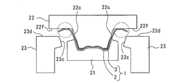
図6,7は、第2の曲げ加工を実行する第2曲げ工程を示している。図6は第2の曲げ加工前を示しており、図7は第2の曲げ加工後を示している。第2曲げ工程では、増厚部4以外の部分を曲げ加工する。第1曲げ加工後は、図6に示すように第1パンチ22とダイ21とでパッチワークブランク1の増厚部4のみが挟み込まれた状態である。換言すれば、増厚部4以外の部分(後述するハット形のつば部120)は、挟み込まれていない。
FIGS. 6 and 7 show a second bending step for performing the second bending. FIG. 6 shows a state before the second bending, and FIG. 7 shows a state after the second bending. In the second bending step, portions other than the thickened portion 4 are bent. After the first bending, as shown in FIG. 6, only the thickened portion 4 of the patchwork blank 1 is sandwiched between the first punch 22 and the die 21. In other words, portions other than the thickened portion 4 (hat-shaped flange 120 described later) are not sandwiched.
第2曲げ工程では、図6の状態から第1パンチ22およびダイ21のプレス圧を維持しつつ、第2パンチ23が、カム機構14(図3参照)から力を受け、斜め上方(図7の矢印参照)に駆動される。即ち、左右両側から第2パンチ23をパッチワークブランク1に近づけ、第1パンチ22と第2パンチ23とによってパッチワークブランク1の増厚部4以外の部分を挟み込み、増厚部4以外の部分を曲げ加工する。詳細には、第2パンチ23の側面23cと第1パンチ22の側面22cとによってパッチワークブランク1を挟み込むとともに、第2パンチ23の上面23dと第1パンチ22のフランジ面22fとによってパッチワークブランク1を挟み込む。本工程によって、ハット形のつば部120(図2,8参照)が成形される。
In the second bending step, the second punch 23 receives a force from the cam mechanism 14 (see FIG. 3) while maintaining the pressing pressure of the first punch 22 and the die 21 from the state of FIG. (See arrow). That is, the second punch 23 is brought closer to the patchwork blank 1 from both left and right sides, the first punch 22 and the second punch 23 sandwich the portion other than the thickened portion 4 of the patchwork blank 1, and the portions other than the thickened portion 4 To bend. More specifically, the patchwork blank 1 is sandwiched between the side surface 23c of the second punch 23 and the side surface 22c of the first punch 22, and the patchwork blank 1 is sandwiched between the upper surface 23d of the second punch 23 and the flange surface 22f of the first punch 22. Insert 1. By this step, the hat-shaped flange 120 (see FIGS. 2 and 8) is formed.
このようにして図8に示すような増厚部4を有するハット形のBピラー100を製造することができる。
よ う Thus, the hat-shaped B pillar 100 having the thickened portion 4 as shown in FIG. 8 can be manufactured.
本実施形態によれば、以下のメリットがある。
According to the present embodiment, there are the following advantages.
増厚部4とそれ以外の部分とで曲げ加工の工程を分けているため、ベースワーク2とパッチワーク3の接合部に応力が集中することを防止でき、当該接合部において意図しない割れや折れ曲がりが発生することを防止できる。従って、それぞれの部分を正確に曲げ加工できる。ここで、「異なる工程」とは広義に解釈されるものであり、同時に行われるものを除き、多段階で行われるものを示す。従って、「異なる工程」には、複数回のプレスに分けて曲げ加工を行うものだけでなく、1回のプレスで多段階で曲げ加工を行うものを含む。なお、増厚部4の曲げ加工の工程と、増厚部4以外の部分の曲げ加工の工程とは、いずれが先に実行されてもよい。
Since the bending process is separated between the thickened portion 4 and the other portions, it is possible to prevent stress from being concentrated on the joint between the base work 2 and the patchwork 3, and to cause unintended cracking or bending at the joint. Can be prevented from occurring. Therefore, each part can be bent accurately. Here, “different steps” are to be interpreted in a broad sense, and indicate steps performed in multiple steps, except steps performed simultaneously. Therefore, the “different process” includes not only a process in which bending is performed by pressing a plurality of times but also a process in which bending is performed in multiple stages by one press. Either the step of bending the thickened portion 4 or the step of bending the portion other than the thickened portion 4 may be performed first.
増厚部4とそれ以外の部分とを曲げ加工する機構を第1機構と第2機構とに分けているため、増厚部4とそれ以外の部分とをそれぞれ正確に曲げ加工できる。
(4) Since the mechanism for bending the thickened portion 4 and other portions is divided into the first mechanism and the second mechanism, the thickened portion 4 and the other portions can be bent accurately.
第1機構と第2機構とによって1つのプレス成形装置10で2つのプレス方向を実現できる。従って、ハット形状のような複数の曲げ部を有する形状を正確に曲げ加工できる。好ましくは、第1機構と第2機構は連動し、プレス成形装置10の1回のプレスで2段階の曲げ加工を行う。
2 Two press directions can be realized by one press forming apparatus 10 by the first mechanism and the second mechanism. Therefore, a shape having a plurality of bent portions such as a hat shape can be accurately bent. Preferably, the first mechanism and the second mechanism are interlocked, and perform two-stage bending with a single press of the press forming apparatus 10.
軟鋼ないしホットスタンプ材のように曲げ加工性が良好な部材をパッチワークブランク1に使用しているため、意図しない割れや折れ曲がりを一層防止できる。また、軟鋼ないしホットスタンプ材のような強度が比較的に低い部材には、増厚部4を設けるなどして補強することが必要となることがある。従って、増厚部4を形成して補強するとともに、上記方法によって意図しない割れや折れ曲がりを防止して正確な曲げ加工を実現できることは有効である。
(4) Since a member having good bending workability such as mild steel or hot stamping material is used for the patchwork blank 1, unintended cracking and bending can be further prevented. In addition, a member having relatively low strength such as mild steel or a hot stamp material may need to be reinforced by providing the thickened portion 4 or the like. Therefore, it is effective that the thickened portion 4 is formed to reinforce, and that the above-described method can prevent an unintended crack or bend to realize accurate bending.
自動車のBピラーは、側面衝突に対して車室内を保護するために一定の強度を要する。また、組み立て性を考慮して正確なハット形が求められる。従って、本実施形態の方法を使用することで、高強度であるとともに正確なハット形のBピラー100を製造できる。
B The B pillar of a car needs a certain strength to protect the cabin against side collision. In addition, an accurate hat shape is required in consideration of assemblability. Therefore, by using the method of the present embodiment, a high-strength and accurate hat-shaped B pillar 100 can be manufactured.
(第2実施形態)
図9,10に示す第2実施形態では、第1実施形態のダイ21(図3参照)として2種類の曲げ駒30,40を使用する。また、パッチワーク3の形状が第1実施形態と異なる。これらに関する以外は、第1実施形態と実質的に同じである。従って、第1実施形態と同じ部分については説明を省略する場合がある。 (2nd Embodiment)
In the second embodiment shown in FIGS. 9 and 10, two types of bending pieces 30 and 40 are used as the die 21 (see FIG. 3) of the first embodiment. Further, the shape of the patchwork 3 is different from that of the first embodiment. Except for these, it is substantially the same as the first embodiment. Therefore, description of the same parts as those in the first embodiment may be omitted.
図9,10に示す第2実施形態では、第1実施形態のダイ21(図3参照)として2種類の曲げ駒30,40を使用する。また、パッチワーク3の形状が第1実施形態と異なる。これらに関する以外は、第1実施形態と実質的に同じである。従って、第1実施形態と同じ部分については説明を省略する場合がある。 (2nd Embodiment)
In the second embodiment shown in FIGS. 9 and 10, two types of bending
図9は第1曲げ工程を示し、図10は第2曲げ加工を示している。
FIG. 9 shows the first bending process, and FIG. 10 shows the second bending process.
第1の曲げ工程では、第1曲げ駒30を使用して増厚部4を曲げ加工する。第1曲げ駒30は、増厚部4の形状に対応した形状を有している。第1曲げ駒30は、第1パンチ22の左右に配置された第1側部曲げ駒31と、第1側部曲げ駒31の間に配置された第1下部曲げ駒32とを備える。第1側部曲げ駒31は、第1パンチ22の角部22bから段差22dまでの部分に対向して配置され、当該部分のパッチワークブランク1を第1パンチ22とともに挟み込んで曲げ加工する。第1下部曲げ駒32は、第1パンチ22の角部22eから頂部22aまでの部分に対向して配置され、当該部分のパッチワークブランク1を第1パンチ22とともに挟み込んで曲げ加工する。
で は In the first bending step, the thickened portion 4 is bent using the first bending piece 30. The first bending piece 30 has a shape corresponding to the shape of the thickened portion 4. The first bending piece 30 includes a first side bending piece 31 disposed on the left and right of the first punch 22 and a first lower bending piece 32 disposed between the first side bending pieces 31. The first side bending piece 31 is arranged to face a portion from the corner 22b to the step 22d of the first punch 22. The first side bending piece 31 is bent by sandwiching the patchwork blank 1 of the portion together with the first punch 22. The first lower bending piece 32 is disposed so as to face a portion from the corner 22 e to the top 22 a of the first punch 22, and bends the patchwork blank 1 in that portion together with the first punch 22.
第2の曲げ工程では、第2曲げ駒40を使用して増厚部4以外の部分を曲げ加工する。第2曲げ駒40は、増厚部4以外の部分の形状にも対応した形状を有している。第2曲げ駒40は、第1パンチ22の左右に配置された第2側部曲げ駒41と、第2側部曲げ駒41の間に配置された第2下部曲げ駒42とを備える。第2側部曲げ駒41は、第1パンチ22の角部22bからフランジ面22fまでの部分に対向して配置され、当該部分のパッチワークブランク1を第1パンチ22とともに挟み込んで曲げ加工する。第2下部曲げ駒42は、第1下部曲げ駒32と同じものである。
In the second bending step, a portion other than the thickened portion 4 is bent using the second bending piece 40. The second bending piece 40 has a shape corresponding to the shape of the portion other than the thickened portion 4. The second bending piece 40 includes a second side bending piece 41 disposed on the left and right of the first punch 22 and a second lower bending piece 42 disposed between the second side bending pieces 41. The second side bending piece 41 is disposed so as to face a portion from the corner 22b of the first punch 22 to the flange surface 22f, and the patchwork blank 1 in the portion is sandwiched together with the first punch 22 and bent. The second lower bending piece 42 is the same as the first lower bending piece 32.
1つのプレス成形装置10で第1曲げ工程と第2曲げ工程とを実行するためには、2回のプレスを行う。具体的には、第1曲げ工程にて1回目のプレスを実行した後に、プレス成形装置10の第1曲げ駒30を第2曲げ駒40に交換し、第2曲げ工程にて2回目のプレスを実行する。
、 2 In order to execute the first bending step and the second bending step with one press forming apparatus 10, two presses are performed. Specifically, after performing the first press in the first bending step, the first bending piece 30 of the press forming apparatus 10 is replaced with the second bending piece 40, and the second pressing in the second bending step is performed. Execute
(第1変形例)
図11,12に示す第2実施形態の第1変形例のように、第1曲げ駒30は、一体型であってもよい。同様に、第2曲げ駒40も、一体型であってもよい。曲げ加工の態様については前述と同様である。 (First Modification)
As in a first modification of the second embodiment shown in FIGS. 11 and 12, thefirst bending piece 30 may be of an integral type. Similarly, the second bending piece 40 may be an integral type. The mode of bending is the same as described above.
図11,12に示す第2実施形態の第1変形例のように、第1曲げ駒30は、一体型であってもよい。同様に、第2曲げ駒40も、一体型であってもよい。曲げ加工の態様については前述と同様である。 (First Modification)
As in a first modification of the second embodiment shown in FIGS. 11 and 12, the
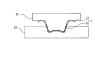
(第2変形例)
図13,14に示す第2実施形態の第2変形例のように、2段階で絞り加工(曲げ加工)を行ってもよい。本変形例では、まず、図13を参照して、第1曲げ駒35と浅絞りパンチ24とで浅い絞り加工を行っている。次に、図14を参照して、第2曲げ駒45と深絞りパンチ25とで深絞り加工を行っている。 (Second Modification)
As in a second modification of the second embodiment shown in FIGS. 13 and 14, drawing (bending) may be performed in two stages. In this modification, first, referring to FIG. 13, shallow drawing is performed by thefirst bending piece 35 and the shallow drawing punch 24. Next, referring to FIG. 14, deep drawing is performed by the second bending piece 45 and the deep drawing punch 25.
図13,14に示す第2実施形態の第2変形例のように、2段階で絞り加工(曲げ加工)を行ってもよい。本変形例では、まず、図13を参照して、第1曲げ駒35と浅絞りパンチ24とで浅い絞り加工を行っている。次に、図14を参照して、第2曲げ駒45と深絞りパンチ25とで深絞り加工を行っている。 (Second Modification)
As in a second modification of the second embodiment shown in FIGS. 13 and 14, drawing (bending) may be performed in two stages. In this modification, first, referring to FIG. 13, shallow drawing is performed by the
浅絞りパンチ24および深絞りパンチ25は、前述の第2実施形態の第1パンチ22(図9参照)と概ね同じ形状を有している。ただし、本変形例では、ベースワーク2に1枚のパッチワーク3が溶接されたパッチワークブランク1を絞り加工している。パッチワーク3は、パッチワークブランク1がハット形に形成された際に頂部110(図8参照)全体を覆うようにベースワーク2に溶接されている。このパッチワークブランク1の形状に対応して、本変形例の浅絞りパンチ24および深絞りパンチ25は前述の突部22a2(図3参照)を有していない。また、浅絞りパンチ24は、深絞りパンチ25よりも相対的に下方への突出量が小さく、本変形例では突出量が深絞りパンチ25の半分程度である。
The shallow-drawing punch 24 and the deep-drawing punch 25 have substantially the same shape as the first punch 22 of the second embodiment (see FIG. 9). However, in this modified example, the patchwork blank 1 in which one patchwork 3 is welded to the basework 2 is drawn. The patchwork 3 is welded to the basework 2 so as to cover the entire top 110 (see FIG. 8) when the patchwork blank 1 is formed in a hat shape. Corresponding to the shape of the patchwork blank 1, the shallow-drawing punch 24 and the deep-drawing punch 25 of the present modified example do not have the above-described protrusion 22a2 (see FIG. 3). Further, the shallow-drawing punch 24 has a relatively smaller amount of protrusion downward than the deep-drawing punch 25, and in this modification, the protrusion amount is about half that of the deep-drawing punch 25.
第1曲げ駒35は、前述の第2実施形態の第1曲げ駒30(図9参照)と実質的に同じ形状を有している。また、第2曲げ駒45も、前述の第2実施形態の第2曲げ駒40(図9参照)と実質的に同じ形状を有している。
The first bending piece 35 has substantially the same shape as the first bending piece 30 (see FIG. 9) of the second embodiment. Also, the second bending piece 45 has substantially the same shape as the second bending piece 40 (see FIG. 9) of the second embodiment described above.
本実施形態およびその変形例によれば、第1曲げ駒30によって増厚部4を曲げ加工できるともに、第2曲げ駒40によって増厚部4以外の部分を曲げ加工できる。これらの2つの曲げ駒30,40を付け替えて使用することで、簡易な構成の1つのプレス成形装置10で2つの工程の曲げ加工を実現できる。
According to the present embodiment and its modified example, the thickened portion 4 can be bent by the first bending piece 30 and a portion other than the thickened portion 4 can be bent by the second bending piece 40. By replacing these two bending pieces 30 and 40 and using them, one press forming apparatus 10 having a simple configuration can realize bending in two steps.
以上より、本発明の具体的な実施形態およびその変形例について説明したが、本発明は上記形態に限定されるものではなく、この発明の範囲内で種々変更して実施することができる。例えば、個々の実施形態の内容を適宜組み合わせたものを、この発明の一実施形態としてもよい。
Although specific embodiments of the present invention and modifications thereof have been described above, the present invention is not limited to the above-described embodiments, and can be implemented with various modifications within the scope of the present invention. For example, an embodiment of the present invention may be appropriately combined with the contents of the individual embodiments.
また、本発明の適用対象は上述のBピラー100に限定されない。例えば、車両用骨格部材のドアビームおよびロッカー等に対しても本発明は適用可能である。
適用 In addition, the application target of the present invention is not limited to the B pillar 100 described above. For example, the present invention is also applicable to a door beam, a locker, and the like of a vehicle frame member.
また、上記各実施形態では、1枚または2枚のパッチワーク3をベースワーク2に溶接したパッチワークブランク1を曲げ加工する例について説明したが、溶接するパッチワーク3の枚数は特に限定されず、3枚以上であってもよい。パッチワークブランク1の曲げ加工形状もハット形に限定されず、パッチワークブランク1は任意の形状に曲げ加工され得る。
Further, in each of the above-described embodiments, the example in which the patchwork blank 1 in which one or two patchworks 3 are welded to the base work 2 is bent is described, but the number of the patchwork 3 to be welded is not particularly limited. Or three or more. The bending shape of the patchwork blank 1 is not limited to the hat shape, and the patchwork blank 1 can be bent into an arbitrary shape.
1 パッチワークブランク
2 ベースワーク
3 パッチワーク
4 増厚部
10 プレス成形装置
11 固定台
12 スライドプレート
13 駆動機構(第1機構)
14 カム機構(第2機構)
20 金型
21 ダイ(第1機構)
21a 底面
21b 角部
21c 側面
22 第1パンチ(第1機構、第2機構)
22a 頂部
22a1 平坦面
22a2 突部
22b 角部
22c 側面
22d 段差
22e 角部
22f フランジ面
23 第2パンチ(第2機構)
23a 基部
23b 先端部
23c 側面
23d 上面
24 浅絞りパンチ(第1機構)
25 深絞りパンチ(第2機構)
30,35 第1曲げ駒(第1機構)
31 第1側部曲げ駒
32 第1下部曲げ駒
40,45 第2曲げ駒(第2機構)
41 第2側部曲げ駒
42 第2下部曲げ駒
100 Bピラー
110 頂部
120 つば部 DESCRIPTION OFSYMBOLS 1 Patchwork blank 2 Basework 3 Patchwork 4 Thickening part 10 Press molding device 11 Fixed base 12 Slide plate 13 Drive mechanism (1st mechanism)
14 Cam mechanism (second mechanism)
20mold 21 die (first mechanism)
21a Bottom surface 21b Corner 21c Side surface 22 First punch (first mechanism, second mechanism)
22a Top 22a1 Flatsurface 22a2 Projection 22b Corner 22c Side 22d Step 22e Corner 22f Flange surface 23 Second punch (second mechanism)
23a base 23b tip 23c side 23d top 24 shallow drawing punch (first mechanism)
25 Deep drawing punch (second mechanism)
30, 35 First bending piece (First mechanism)
31 firstside bending piece 32 first lower bending piece 40, 45 second bending piece (second mechanism)
41 Secondside bending piece 42 Second lower bending piece 100 B pillar 110 Top part 120 Collar part
2 ベースワーク
3 パッチワーク
4 増厚部
10 プレス成形装置
11 固定台
12 スライドプレート
13 駆動機構(第1機構)
14 カム機構(第2機構)
20 金型
21 ダイ(第1機構)
21a 底面
21b 角部
21c 側面
22 第1パンチ(第1機構、第2機構)
22a 頂部
22a1 平坦面
22a2 突部
22b 角部
22c 側面
22d 段差
22e 角部
22f フランジ面
23 第2パンチ(第2機構)
23a 基部
23b 先端部
23c 側面
23d 上面
24 浅絞りパンチ(第1機構)
25 深絞りパンチ(第2機構)
30,35 第1曲げ駒(第1機構)
31 第1側部曲げ駒
32 第1下部曲げ駒
40,45 第2曲げ駒(第2機構)
41 第2側部曲げ駒
42 第2下部曲げ駒
100 Bピラー
110 頂部
120 つば部 DESCRIPTION OF
14 Cam mechanism (second mechanism)
20
22a Top 22a1 Flat
25 Deep drawing punch (second mechanism)
30, 35 First bending piece (First mechanism)
31 first
41 Second
Claims (6)
- ベースワークにパッチワークを溶接して増厚部を形成したパッチワークブランクを準備し、
前記パッチワークブランクの前記増厚部のみを曲げ加工し、
前記増厚部の曲げ加工とは異なる工程で前記増厚部以外の部分を曲げ加工する
ことを含む、プレス成形品の製造方法。 Prepare a patchwork blank with a thickened part formed by welding the patchwork to the basework,
Bending only the thickened part of the patchwork blank,
A method of manufacturing a press-formed product, comprising bending a portion other than the thickened portion in a step different from the bending process of the thickened portion. - 前記増厚部のみを曲げ加工する第1機構と、前記増厚部以外の部分を曲げ加工する第2機構とを備えるプレス成形装置を使用して前記パッチワークブランクの曲げ加工を行う、請求項1に記載のプレス成形品の製造方法。 The bending of the patchwork blank is performed using a press forming apparatus including a first mechanism for bending only the thickened portion and a second mechanism for bending a portion other than the thickened portion. 2. The method for producing a press-formed product according to 1.
- 前記第1機構は、鉛直方向に駆動して前記増厚部に鉛直方向のプレス荷重を加え、
前記第2機構は、前記第1機構の鉛直方向のプレス荷重を鉛直方向から傾斜した方向に変換するカム機構を有し、前記カム機構によって鉛直方向から傾斜した方向に駆動して前記増厚部以外の部分に鉛直方向から傾斜した方向のプレス荷重を加える、請求項2に記載のプレス成形品の製造方法。 The first mechanism is driven vertically to apply a vertical press load to the thickened portion,
The second mechanism has a cam mechanism that converts a vertical press load of the first mechanism into a direction inclined from the vertical direction, and is driven by the cam mechanism in a direction inclined from the vertical direction to increase the thickness. The method for producing a press-formed product according to claim 2, wherein a press load in a direction inclined from the vertical direction is applied to the other parts. - 前記第1機構は、前記増厚部の形状に対応した第1曲げ駒を有し、
前記第2機構は、前記増厚部以外の部分の形状に対応した第2曲げ駒を有する、請求項2に記載のプレス成形品の製造方法。 The first mechanism has a first bending piece corresponding to the shape of the thickened portion,
The method for manufacturing a press-formed product according to claim 2, wherein the second mechanism has a second bending piece corresponding to a shape of a portion other than the thickened portion. - 前記パッチワークブランクは、軟鋼ないしホットスタンプ材からなる、請求項1から請求項4のいずれか1項に記載のプレス成形品の製造方法。 The method of manufacturing a press-formed product according to any one of claims 1 to 4, wherein the patchwork blank is made of a mild steel or a hot stamp material.
- 前記プレス成形品は自動車のBピラーであり、断面形状がハット形である、請求項1から請求項4のいずれか1項に記載のプレス成形品の製造方法。 The method of manufacturing a press-formed product according to any one of claims 1 to 4, wherein the press-formed product is a B pillar of an automobile and has a hat-shaped cross section.
Priority Applications (3)
| Application Number | Priority Date | Filing Date | Title |
|---|---|---|---|
| US17/053,423 US20210229156A1 (en) | 2018-06-26 | 2019-05-13 | Method for manufacturing press-molded article |
| EP19824688.6A EP3815807A4 (en) | 2018-06-26 | 2019-05-13 | Method for manufacturing press-molded article |
| CN201980042895.6A CN112313020B (en) | 2018-06-26 | 2019-05-13 | Method for manufacturing press-formed article |
Applications Claiming Priority (2)
| Application Number | Priority Date | Filing Date | Title |
|---|---|---|---|
| JP2018121198A JP6985989B2 (en) | 2018-06-26 | 2018-06-26 | Manufacturing method of press-molded products |
| JP2018-121198 | 2018-06-26 |
Publications (1)
| Publication Number | Publication Date |
|---|---|
| WO2020003767A1 true WO2020003767A1 (en) | 2020-01-02 |
Family
ID=68986254
Family Applications (1)
| Application Number | Title | Priority Date | Filing Date |
|---|---|---|---|
| PCT/JP2019/018848 WO2020003767A1 (en) | 2018-06-26 | 2019-05-13 | Method for manufacturing press-molded article |
Country Status (5)
| Country | Link |
|---|---|
| US (1) | US20210229156A1 (en) |
| EP (1) | EP3815807A4 (en) |
| JP (1) | JP6985989B2 (en) |
| CN (1) | CN112313020B (en) |
| WO (1) | WO2020003767A1 (en) |
Cited By (1)
| Publication number | Priority date | Publication date | Assignee | Title |
|---|---|---|---|---|
| JP2021130427A (en) * | 2020-02-21 | 2021-09-09 | 豊田鉄工株式会社 | Vehicle pillar structure |
Families Citing this family (2)
| Publication number | Priority date | Publication date | Assignee | Title |
|---|---|---|---|---|
| WO2023229025A1 (en) * | 2022-05-26 | 2023-11-30 | 日本製鉄株式会社 | Hot-pressing device, production method for hot-pressed molded article, and hot-pressed molded article |
| KR102471975B1 (en) * | 2022-08-10 | 2022-11-29 | (주)썬텍솔루션 | the method of manufacturing insulating sheet |
Citations (5)
| Publication number | Priority date | Publication date | Assignee | Title |
|---|---|---|---|---|
| WO2016075937A1 (en) * | 2014-11-12 | 2016-05-19 | 新日鐵住金株式会社 | Manufacturing method and manufacturing device for press-molded article |
| WO2017103138A1 (en) * | 2015-12-18 | 2017-06-22 | Autotech Engineering A.I.E. | B-pillar central beam and method for manufacturing |
| JP6179696B1 (en) * | 2015-12-08 | 2017-08-16 | 新日鐵住金株式会社 | PRESS-MOLDED PRODUCTION METHOD, PRESS DEVICE, AND PRESS LINE |
| JP2017177115A (en) | 2016-03-28 | 2017-10-05 | 新日鐵住金株式会社 | Press molding product, press molding method, and apparatus therefor |
| JP6340389B2 (en) * | 2016-07-19 | 2018-06-06 | 東亜工業株式会社 | Hot press device, hot press method, and automobile body part manufacturing method |
Family Cites Families (9)
| Publication number | Priority date | Publication date | Assignee | Title |
|---|---|---|---|---|
| US5941110A (en) * | 1997-05-12 | 1999-08-24 | Northern University | Adaptive method and apparatus for forming tailor welded blanks |
| KR20020028233A (en) * | 2000-10-09 | 2002-04-17 | 이계안 | Assembly pannel-molding method |
| JP2011083807A (en) * | 2009-10-16 | 2011-04-28 | Daihatsu Motor Co Ltd | Method for manufacturing component having hat-shaped cross section |
| DE102009052210B4 (en) * | 2009-11-06 | 2012-08-16 | Voestalpine Automotive Gmbh | Method for producing components with regions of different ductility |
| JP6418249B2 (en) * | 2014-12-10 | 2018-11-07 | 新日鐵住金株式会社 | Blank, molded product manufacturing method, mold and blank manufacturing method |
| US10799930B2 (en) * | 2015-03-03 | 2020-10-13 | Nippon Steel Corporation | Press forming method and press forming apparatus |
| JP2017140636A (en) * | 2016-02-12 | 2017-08-17 | 株式会社豊田中央研究所 | Hot-press molding method |
| EP3485996B1 (en) * | 2016-07-13 | 2022-06-01 | Nippon Steel Corporation | Hot-stamping formed article, structural member using the same, and manufacturing method of hot-stamping formed article |
| DE102016013466A1 (en) * | 2016-11-12 | 2017-05-11 | Daimler Ag | Body component for a motor vehicle and method for producing a body component |
-
2018
- 2018-06-26 JP JP2018121198A patent/JP6985989B2/en active Active
-
2019
- 2019-05-13 CN CN201980042895.6A patent/CN112313020B/en active Active
- 2019-05-13 EP EP19824688.6A patent/EP3815807A4/en active Pending
- 2019-05-13 US US17/053,423 patent/US20210229156A1/en active Pending
- 2019-05-13 WO PCT/JP2019/018848 patent/WO2020003767A1/en unknown
Patent Citations (5)
| Publication number | Priority date | Publication date | Assignee | Title |
|---|---|---|---|---|
| WO2016075937A1 (en) * | 2014-11-12 | 2016-05-19 | 新日鐵住金株式会社 | Manufacturing method and manufacturing device for press-molded article |
| JP6179696B1 (en) * | 2015-12-08 | 2017-08-16 | 新日鐵住金株式会社 | PRESS-MOLDED PRODUCTION METHOD, PRESS DEVICE, AND PRESS LINE |
| WO2017103138A1 (en) * | 2015-12-18 | 2017-06-22 | Autotech Engineering A.I.E. | B-pillar central beam and method for manufacturing |
| JP2017177115A (en) | 2016-03-28 | 2017-10-05 | 新日鐵住金株式会社 | Press molding product, press molding method, and apparatus therefor |
| JP6340389B2 (en) * | 2016-07-19 | 2018-06-06 | 東亜工業株式会社 | Hot press device, hot press method, and automobile body part manufacturing method |
Non-Patent Citations (1)
| Title |
|---|
| See also references of EP3815807A4 |
Cited By (2)
| Publication number | Priority date | Publication date | Assignee | Title |
|---|---|---|---|---|
| JP2021130427A (en) * | 2020-02-21 | 2021-09-09 | 豊田鉄工株式会社 | Vehicle pillar structure |
| JP7217717B2 (en) | 2020-02-21 | 2023-02-03 | 豊田鉄工株式会社 | Vehicle pillar structure |
Also Published As
| Publication number | Publication date |
|---|---|
| EP3815807A1 (en) | 2021-05-05 |
| CN112313020B (en) | 2023-03-10 |
| US20210229156A1 (en) | 2021-07-29 |
| CN112313020A (en) | 2021-02-02 |
| EP3815807A4 (en) | 2022-03-16 |
| JP2020001055A (en) | 2020-01-09 |
| JP6985989B2 (en) | 2021-12-22 |
Similar Documents
| Publication | Publication Date | Title |
|---|---|---|
| KR101486707B1 (en) | Method of manufacturing closed structural member, press-forming device, and closed structural member | |
| KR102407168B1 (en) | The manufacturing method and manufacturing device of the press parts | |
| US8844581B2 (en) | Closed structure parts, method and press forming apparatus for manufacturing the same | |
| WO2020003767A1 (en) | Method for manufacturing press-molded article | |
| KR20190086583A (en) | Panel-shaped molded product | |
| JP4600432B2 (en) | Press-molded product and method for producing press-molded product | |
| WO2016140287A1 (en) | Press-forming method and press-forming device | |
| WO2015155943A1 (en) | Press-molded article, automotive structural member provided with same, and manufacturing method and manufacturing device for said press-molded article | |
| JP5515279B2 (en) | Press-molded product, press-molded product manufacturing method and manufacturing apparatus | |
| US11534815B2 (en) | Press formed product, automobile structural member with the press formed product, and method for producing press formed product | |
| JP5866988B2 (en) | Sheet metal bending wrinkle correction device | |
| WO2018034104A1 (en) | Automobile-body press-formed component and manufacturing method therefor | |
| JP6311853B1 (en) | Hot stamp molded product, manufacturing method and manufacturing apparatus thereof | |
| KR102105348B1 (en) | Press forming method | |
| JP6665612B2 (en) | Method for manufacturing press-formed product and press device | |
| JP6094699B2 (en) | PRESS-MOLDED PRODUCTION METHOD, PRESS-MOLDED PRODUCT, AND PRESS DEVICE | |
| JP6265315B1 (en) | Press-molded parts for automobile bodies and methods for producing the same | |
| JP5739283B2 (en) | Press forming method of plate workpiece | |
| JP7110737B2 (en) | Press molding method and press molding apparatus | |
| JP5829601B2 (en) | Tailored blank structure and mold for molding the same | |
| JP6662142B2 (en) | Method of manufacturing panel-shaped molded product | |
| WO2023127695A1 (en) | Press-forming apparatus and method for producing press-formed article | |
| JP7080157B2 (en) | Manufacturing method and manufacturing equipment for press-molded products | |
| JP7181506B2 (en) | press mold | |
| JP7261826B2 (en) | Method for manufacturing press-molded products |
Legal Events
| Date | Code | Title | Description |
|---|---|---|---|
| 121 | Ep: the epo has been informed by wipo that ep was designated in this application |
Ref document number: 19824688 Country of ref document: EP Kind code of ref document: A1 |
|
| NENP | Non-entry into the national phase |
Ref country code: DE |
|
| ENP | Entry into the national phase |
Ref document number: 2019824688 Country of ref document: EP Effective date: 20210126 |