KR20200033528A - Molding device for forming subway window frame - Google Patents
Molding device for forming subway window frame Download PDFInfo
- Publication number
- KR20200033528A KR20200033528A KR1020180112903A KR20180112903A KR20200033528A KR 20200033528 A KR20200033528 A KR 20200033528A KR 1020180112903 A KR1020180112903 A KR 1020180112903A KR 20180112903 A KR20180112903 A KR 20180112903A KR 20200033528 A KR20200033528 A KR 20200033528A
- Authority
- KR
- South Korea
- Prior art keywords
- window frame
- die
- molding
- bending
- lower die
- Prior art date
Links
Images


Classifications
-
- B—PERFORMING OPERATIONS; TRANSPORTING
- B21—MECHANICAL METAL-WORKING WITHOUT ESSENTIALLY REMOVING MATERIAL; PUNCHING METAL
- B21D—WORKING OR PROCESSING OF SHEET METAL OR METAL TUBES, RODS OR PROFILES WITHOUT ESSENTIALLY REMOVING MATERIAL; PUNCHING METAL
- B21D5/00—Bending sheet metal along straight lines, e.g. to form simple curves
- B21D5/02—Bending sheet metal along straight lines, e.g. to form simple curves on press brakes without making use of clamping means
- B21D5/0209—Tools therefor
-
- B—PERFORMING OPERATIONS; TRANSPORTING
- B21—MECHANICAL METAL-WORKING WITHOUT ESSENTIALLY REMOVING MATERIAL; PUNCHING METAL
- B21D—WORKING OR PROCESSING OF SHEET METAL OR METAL TUBES, RODS OR PROFILES WITHOUT ESSENTIALLY REMOVING MATERIAL; PUNCHING METAL
- B21D37/00—Tools as parts of machines covered by this subclass
- B21D37/10—Die sets; Pillar guides
Landscapes
- Engineering & Computer Science (AREA)
- Mechanical Engineering (AREA)
- Bending Of Plates, Rods, And Pipes (AREA)
Abstract
Description
본 발명은 전철 창틀 성형용 금형장치에 관한 것으로서, 더욱 상세하게는 전철의 창틀에 유리창을 설치하기 위해 성형되어 있는 홀의 가장자리 부분을 벤딩하는 프레스 금형장치에 관한 것이다.The present invention relates to a mold apparatus for molding a window frame for trains, and more particularly, to a press mold apparatus for bending an edge portion of a hole that is formed to install a glass window on a window frame of a train.
일반적으로 펀칭 프레스는 펀치 작동을 통해 얇은 판상 제품인 가공소재의 소정 부위에 전단력을 가하여 가공소재로부터 배제되는 스크랩을 취출함으로써, 특정 형상의 스크랩이 관통된 판상 제품을 생산하는 금형장치이다. In general, a punching press is a mold device that produces a plate-shaped product through which a scrap of a specific shape is penetrated by applying a shearing force to a predetermined portion of a thin plate-shaped product through a punching operation to take out scraps excluded from the processed material.
이러한 펀칭 프레스는 보통 가공소재가 안착 고정되고 스크랩 취출을 위한 펀칭홀이 형성된 하부 다이와, 상기 하부 다이의 펀칭홀에 형합 삽입되고 하부 다이에 고정된 가공소재를 전후 작동에 의해 펀칭하는 펀치가 설치된 상부 펀치를 포함하는 구조로 이루어진다. In the punching press, a lower die having a punched hole for inserting and fixing scraps is usually inserted into the punching hole of the lower die, and a punching punch punching the work material fixed to the lower die by front-rear operation is installed. It consists of a structure comprising a punch.
이와 같은 펀칭 프레스는 일반적으로 가공소재가 하부 다이와 상부 펀치 사이로 통과하여 단속적으로 이송되도록 하면서 작업을 수행하게 되고, 가공소재가 정지되는 동안 상부 펀치가 하강하여 가공소재의 소정 부위를 전단력을 가해 펀칭홀 내부로 밀어냄으로써 원하는 형상으로 성형하게 되며, 이러한 성형 공정에 의해 생성된 스크랩은 펀칭홀을 통해 외부로 배출되는 한편, 선(先) 가공되어 있는 홀의 가장자리 부분을 90°벤딩하는 성형 공정을 수행하게 된다. Such a punching press generally performs work while allowing the processing material to pass intermittently between the lower die and the upper punch, and the upper punch descends while the processing material is stopped, thereby applying a shearing force to a predetermined portion of the processing material to punch the hole. It is molded into a desired shape by pushing it inside, and the scrap produced by this molding process is discharged to the outside through a punching hole, while performing a forming process of bending the edge portion of a pre-processed hole by 90 °. do.
그러나, 종래 대부분의 펀칭 프레스는 고정되어 있는 하부 다이 상에 가공소재를 고정시킨 상태에서 상하 동작하는 상부 펀치의 전단력이나 가압력을 이용하여 홀을 가공하거나 홀 가장자리를 벤딩하는 방식인 관계로, 특히 홀의 가장자리를 벤딩하는 경우에 벤딩 부위에 주름이 생기거나 정확하게 90°의 각도로 벤딩이 이루어지지 않게 되는 등 벤딩 품질을 확보하는데 어려운 점이 있다. However, most of the punching presses in the prior art have a method of processing a hole or bending a hole edge by using a shearing force or a pressing force of an upper punch that moves up and down in a state in which a processing material is fixed on a fixed lower die. In the case of bending the edge, there is a difficulty in securing bending quality such as wrinkles in the bending portion or bending at an angle of 90 °.
또한, 종래 대부분의 펀칭 프레스는 상부 펀치의 가압력을 이용하여 한 번에 가공소재를 벤딩하는 방식을 채택하고 있기 때문에 고용량의 프레스 설비를 사용해야 하고, 또 상부 펀치는 물론 하부 다이에 부하가 집중되면서 상부 펀치 및 하부 다이가 마모되거나 파손되는 등 금형장치의 내구성 저하 및 수명 단축을 초래하는 단점이 있다. In addition, most conventional punching presses use a method of bending the processing material at a time by using the pressing force of the upper punch, so a high-capacity press equipment must be used, and the upper punch as well as the lower die are concentrated. There is a disadvantage that the durability of the mold device is reduced and the life is shortened, such as the wear and damage of the punch and the lower die.
특히, 전철 창틀 성형을 위한 종래의 금형장치에서는 상부 펀치 및 하부 다이의 구조적 특성 및 작동 방식 등의 한계로 인해 가공소재의 벤딩 폭(벤딩 성형 후의 창틀 플랜지 높이)이 40㎜를 초과하는 경우에 주름이 생기거나 모서리 부분이 울게 되는 등 성형 불량이 많이 발생하게 되고, 결국 40㎜를 초과하는 창틀 플랜지 높이가 요구되는 경우, 40㎜ 이하로 벤딩한 후에 부족한 높이만큼 보조재를 덧붙혀 사용하고 있는 등 창틀 제작과 관련한 효율성 측면에서 불리한 점이 있다.Particularly, in a conventional mold apparatus for forming a window frame for a train, wrinkles when the bending width (the height of the window frame flange after bending molding) exceeds 40 mm due to limitations such as structural characteristics of the upper punch and the lower die and an operating method. When molding defects are generated such as this occurs or the corners are crying, and eventually, a window frame flange height exceeding 40 mm is required, after bending below 40 mm, an auxiliary material is added to the window frame, such as insufficient height, to be used. There are disadvantages in terms of production efficiency.
따라서, 본 발명은 이와 같은 점을 감안하여 안출한 것으로서, 가공소재에 성형되어 있는 홀의 가장자리 벤딩 성형 시, 상하 작동하는 상부 펀치와 이때의 상부 펀치와 연계적으로 상하 동작하는 하부 슬라이드 다이, 그리고 하부 다이의 조합을 이용하여 가공소재의 홀 가장자리를 벤딩 성형하는 새로운 구조 및 방식의 금형장치를 구현함으로써, 우수한 벤딩 품질을 확보할 수 있고, 금형장치의 내구성 및 수명을 향상시킬 수 있으며, 창틀 플랜지의 높이가 40㎜를 초과하는 제품도 문제없이 벤딩 성형할 수 있는 등 제작 가능한 창틀 사양 및 규격의 폭을 넓혀 다양한 창틀을 효율적으로 제작할 수 있는 전철 창틀 성형용 금형장치를 제공하는데 그 목적이 있다. Therefore, the present invention has been devised in view of this point, and when forming the edge of a hole formed in a work material, an upper punch operating up and down and a lower slide die operating up and down in conjunction with the upper punch at this time, and a lower section By using a combination of dies to implement a new structure and method of mold device to bend the hole edge of the processed material, excellent bending quality can be secured, durability and life of the mold device can be improved, and the window frame flange The purpose of the present invention is to provide a mold apparatus for molding a window frame for trains that can efficiently manufacture various window frames by widening the width of specifications and specifications that can be manufactured, such as bending molding even products with a height exceeding 40 mm.
상기 목적을 달성하기 위하여 본 발명에서 제공하는 전철 창틀 성형용 금형장치는 다음과 같은 특징이 있다. In order to achieve the above object, the mold apparatus for molding a train window frame provided by the present invention has the following features.
상기 전철 창틀 성형용 금형장치는 프레스 설비에 설치되어 전철의 창틀에 유리창을 설치하기 위해 성형되어 있는 홀의 가장자리 부분을 벤딩하는 금형장치로서, 중심부에 다이 홀을 가지는 사각틀 구조로 이루어져 프레스 설비 작동 시에 상하 작동하는 상부 펀치와, 상기 상부 펀치와 상하 1조를 이루면서 프레스 설비측에 고정 설치되는 사각블록 구조의 하부 다이와, 상기 하부 다이의 외곽 둘레면에 끼워지면서 상하 슬라이드 가능한 구조로 설치되고 상부 펀치와 함께 가공소재를 위아래에서 붙잡고 하강 작동하면서 가공소재에 대한 벤딩 성형이 이루어지도록 해주는 사각틀 구조의 하부 슬라이드 다이를 포함하는 구조로 이루어진다. The mold device for molding the window frame of a train is a mold device that is installed in a press facility and bends an edge portion of a hole formed to install a glass window on a window frame of a train, and consists of a square frame structure having a die hole in the center. An upper punch that operates up and down, a lower die of a square block structure fixed to the press installation while forming a pair of upper and lower punches, and is fitted in an outer circumferential surface of the lower die and installed in a vertically slidable structure, and an upper punch and It is made of a structure that includes a lower slide die of a square frame structure that holds the processed material together from above and below and moves downwards to allow bending molding for the processed material.
특히, 상기 하부 다이의 상단부 둘레면에는 위에서 아래로 갈수록 바깥쪽으로 넓어지는 형태의 1차 테이퍼 면이 형성될 수 있고, 또 상기 하부 다이의 상단부 둘레면에는 1차 테이퍼 면의 하단에서부터 연이어지면서 위에서 아래로 갈수록 바깥쪽으로 넓어짐과 더불어 1차 테이퍼 면 대비 상대적으로 작은 각도를 가지는 형태의 2차 테이퍼 면이 형성될 수 있다. In particular, a primary tapered surface of a shape widening outward from the top to the bottom may be formed on the circumferential surface of the upper portion of the lower die. The second tapered surface having a relatively small angle compared to the primary tapered surface may be formed as it goes outward.
여기서, 상기 상부 펀치의 하단부 내측면에는 하부 다이에 있는 2차 테이퍼 면과 동일한 각도를 가지는 형태의 펀치 테이퍼 면이 형성될 수 있다. Here, a punch tapered surface having the same angle as the secondary tapered surface on the lower die may be formed on the inner surface of the lower end of the upper punch.
그리고, 상기 하부 슬라이드 다이는 하부 다이측에 상하 이동 가능한 구조로 설치되는 슬라이드 핀에 의해 탄력적으로 지지되면서 슬라이드 핀의 상승 작동 시에 초기 위치로 복귀될 수 있도록 하는 것이 바람직하다. Further, it is preferable that the lower slide die is elastically supported by a slide pin installed in a structure that can be moved up and down on the lower die side, so that it can be returned to an initial position when the slide pin is raised.
본 발명에서 제공하는 전철 창틀 성형용 금형장치는 다음과 같은 효과가 있다. The mold apparatus for molding a train window frame provided by the present invention has the following effects.
첫째, 상부 펀치와 하부 슬라이드 다이의 간의 상하 연계적인 동작관계를 적용함과 더불어 클램핑 공정, 1차 벤딩 공정 및 2차 벤딩 공정을 채택하여, 가공소재를 벤딩 성형하는 금형장치를 제공함으로써, 가공소재의 벤딩 부위에 대한 주름 발생 등의 불량을 막을 수 있고 정확히 90°의 각도로 벤딩할 수 있는 등 우수한 벤딩 품질을 확보할 수 있는 효과가 있다. First, by applying a vertical and downward linking operation relationship between the upper punch and the lower slide die, and adopting a clamping process, a primary bending process, and a secondary bending process, by providing a mold device for bending and forming a processed material, processing material It is possible to prevent defects such as wrinkles in the bending portion of the bend and to secure an excellent bending quality, such as bending at an angle of exactly 90 °.
둘째, 상부 펀치와 하부 슬라이드 다이의 연계적인 동작 및 하부 다이의 테이퍼 구조를 이용한 두 차례의 벤딩 공정으로 가공소재를 벤딩 성형하는 방식을 채택함으로써, 소용량의 프레스 설비만으로도 효율적으로 벤딩 공정을 수행할 수 있으며, 특히 상부 펀치, 하부 슬라이드 다이 및 하부 다이에 부하가 집중되는 현상을 완전히 배제할 수 있는 등 금형장치의 내구성을 향상시킬 수 있는 동시에 수명을 연장시킬 수 있는 효과가 있다. Second, by adopting a method of bending and forming the processed material in two bending processes using the upper punch and the lower slide die and the taper structure of the lower die, it is possible to perform the bending process efficiently with only a small amount of press equipment. In particular, it is possible to improve the durability of the mold apparatus, such as being able to completely eliminate the phenomenon that the load is concentrated on the upper punch, the lower slide die and the lower die, and at the same time, can extend the life.
셋째, 상부 펀치와 하부 슬라이드 다이의 간의 상하 연계적인 작동 메카니즘은 물론 클램핑 공정, 1차 벤딩 공정 및 2차 벤딩 공정을 순차적으로 연속 수행하는 방식을 채택함으로써, 가공소재의 벤딩 폭이 40㎜를 초과하는 경우에도 주름이 생기거나 모서리 부분이 울게 되는 등 성형 불량 문제를 완전히 해소할 수 있고, 따라서 창틀 플랜지의 높이가 40㎜를 초과하는 제품도 문제없이 벤딩 성형할 수 있는 등 제작 가능한 창틀 사양 및 규격의 폭을 넓혀 다양한 창틀을 효율적으로 제작할 수 있는 효과가 있다. Third, by adopting a method of sequentially performing the clamping process, the primary bending process, and the secondary bending process sequentially as well as the up and down linkage operation mechanism between the upper punch and the lower slide die, the bending width of the processed material exceeds 40 mm Even if it is, it is possible to completely solve the problem of molding defects such as wrinkles or corners, so that products with a window frame flange height exceeding 40 mm can be molded without problems, making it possible to manufacture window frame specifications and specifications. It has the effect of making various window frames efficiently by widening the width.
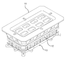
도 1과 도 2는 본 발명의 일 실시예에 따른 전철 창틀 성형용 금형장치를 나타내는 사시도
도 3은 본 발명의 일 실시예에 따른 전철 창틀 성형용 금형장치를 나타내는 평면도
도 4는 도 3의 A-A 선 단면도
도 5는 도 3의 B-B 선 단면도
도 6은 도 3의 C-C 선 단면도
도 7은 도 3의 D-D 선 단면도
도 8은 도 3의 E-E 선 단면도
도 9a 내지 도 9c는 본 발명의 일 실시예에 따른 전철 창틀 성형용 금형장치의 작동상태를 나타내는 단면도1 and 2 is a perspective view showing a mold apparatus for molding a window frame according to an embodiment of the present invention
Figure 3 is a plan view showing a mold apparatus for molding a train window frame according to an embodiment of the present invention
Figure 4 is a cross-sectional view taken along line AA of Figure 3
Figure 5 is a cross-sectional view taken along line BB of Figure 3
Figure 6 is a cross-sectional view taken along line CC of Figure 3
7 is a cross-sectional view taken along line DD of FIG. 3;
8 is a cross-sectional view taken along line EE of FIG. 3;
9A to 9C are cross-sectional views showing an operating state of a mold apparatus for molding a train window frame according to an embodiment of the present invention
이하, 첨부한 도면을 참조하여 본 발명을 상세히 설명하면 다음과 같다. Hereinafter, the present invention will be described in detail with reference to the accompanying drawings.
도 1과 도 2는 본 발명의 일 실시예에 따른 전철 창틀 성형용 금형장치를 나타내는 사시도이고, 도 3은 본 발명의 일 실시예에 따른 전철 창틀 성형용 금형장치를 나타내는 평면도이고, 도 4 내지 도 8은 본 발명의 일 실시예에 따른 전철 창틀 성형용 금형장치를 나타내는 단면도이다. 1 and 2 is a perspective view showing a mold apparatus for molding a train window frame according to an embodiment of the present invention, Figure 3 is a plan view showing a mold apparatus for molding a train window frame according to an embodiment of the present invention, Figures 4 to 8 is a cross-sectional view showing a mold apparatus for molding a train window frame according to an embodiment of the present invention.
도 1 내지 도 8에 도시한 바와 같이, 상기 전철 창틀 성형용 금형장치는 공지의 프레스 설비에 설치되어 전철의 창틀에 유리창을 설치하기 위해 성형되어 있는 홀의 가장자리 부분을 벤딩하는 금형장치로서, 가공소재의 홀 테두리 부분을 함께 맞잡은 상태에서 위아래로 동작하는 상부 펀치와 하부 슬라이드 다이, 그리고 테이퍼 면을 갖는 하부 다이의 조합을 통해 벤딩 공정의 효율성을 높이고 벤딩 품질을 확보할 수 있는 금형장치이다.As shown in Figures 1 to 8, the train window frame molding mold apparatus is installed in a known press equipment to bend the edge portion of the hole formed to install a glass window on the train window frame, a mold device for bending, processing material It is a mold device that can increase the efficiency of the bending process and secure the bending quality through a combination of an upper punch, a lower slide die, and a lower die having a tapered surface, while holding the hole rim of the hole together.
이를 위하여, 상기 전철 창틀 성형용 금형장치는 프레스 설비(미도시)의 상부 가동측에 설치되어 상하 작동하면서 가공소재를 잡고 내려가는 상부 펀치(11)를 포함한다.To this end, the mold apparatus for molding the window frame of the train includes an
상기 상부 펀치(11)는 하부 다이(12)의 관통을 위한 중심부의 다이 홀(10)을 가지면서 다수의 보강용 리브가 형성되어 있는 사각틀 구조의 블록 형태로 이루어지게 되고, 이렇게 이루어진 상부 펀치(11)는 펀치 상단측을 이용하여 프레스 설비의 가동측에 조립된다.The
여기서, 상기 상부 펀치(11)를 프레스 설비의 가동측에 조립하는 구조는 당해 기술분야에서 통상적으로 알려져 있는 구조라면 특별히 제한되지 않고 채택될 수 있다. Here, the structure for assembling the
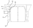
이러한 상부 펀치(11)의 하단부 내측면, 즉 다이 홀(10)의 하단부 내면에는 실질적으로 가공소재를 하부 다이(12)측으로 가압하는 역할을 하는 부분으로서 펀치 가압부(18)가 돌출 형성되며, 이때의 펀치 가압부(18)는 다이 홀(10)의 내면보다 상대적으로 안쪽으로 돌출되어 있게 된다.On the inner surface of the lower end of the
이에 따라, 가공소재가 다이 홀(10)의 내면에 닿지 않도록 한 상태에서 펀치 가압부(18)만으로 가공소재에 대한 벤딩 작업이 실시될 수 있게 된다. Accordingly, a bending operation for the processing material can be performed only with the
특히, 상기 상부 펀치(11)의 하단부 내측면, 즉 하부 다이(12)의 외곽 둘레면과 마주대하는 펀치 가압부(18)의 내면은 펀치 테이퍼 면(16)으로 형성되고, 이때의 펀치 테이퍼 면(16)은 하부 다이(12)에 있는 후술하는 2차 테이퍼 면(15)과 동일한 각도의 기울기를 가지면서 2차 테이퍼 면(15)에 형합 가능한 형태로 이루어질 수 있게 된다. Particularly, the inner surface of the lower end inner surface of the
이에 따라, 가공소재는 하부 다이(12)측의 2차 테이퍼 면(15)과 상부 펀치(11)측의 펀치 테이퍼 면(15) 사이에 가압되면서 벤딩 성형될 수 있게 된다.Accordingly, the work material can be bent while being pressed between the secondary
또한, 상기 전철 창틀 성형용 금형장치는 프레스 설비(미도시)의 하부 고정측에 설치되어 벤딩 성형 시에 상부 펀치(11)와 짝을 이루는, 즉 상부 펀치(11)와 상하 1조를 이루는 하부 다이(12)를 포함한다. In addition, the mold apparatus for molding the window frame of the train is installed on the lower fixed side of the press facility (not shown), and is paired with the
상기 하부 다이(12)는 내외부에 다수의 보강용 리브가 형성되어 있는 동시에 내부가 비어 있는 중공형의 사각블록 형태로 이루어지게 되고, 이렇게 이루어진 하부 다이(12)는 다이 하단측을 이용하여 프레스 설비의 고정측에 조립된다.The
여기서, 상기 하부 다이(12)를 프레스 설비의 고정측에 조립하는 구조는 당해 기술분야에서 통상적으로 알려져 있는 구조라면 특별히 제한되지 않고 채택될 수 있다. Here, the structure for assembling the
특히, 상기 하부 다이(12)에는 가공소재에 대한 벤딩 작업이 여러 차례에 걸쳐 단계적으로 이루어질 수 있도록 해주는 구조로서 1차 테이퍼 면(14)과 2차 테이퍼 면(15)이 구비된다. In particular, the
이를 위하여, 상기 하부 다이(12)의 상단부 둘레면, 즉 사각블록 형태로 이루어진 하부 다이(12)의 상단부 4면 둘레에는 위에서 아래로 갈수록 바깥쪽으로 넓어지는 형태의 1차 테이퍼 면(14)이 형성되고, 이때의 1차 테이퍼 면(14)에 의해 꺽이면서 가공소재가 소정의 각도로 1차 벤딩될 수 있게 된다. To this end, a primary
여기서, 상기 1차 테이퍼 면(14)의 각도는 수직선 기준으로 약 20∼30°정도로 설정하는 것이 바람직하다. Here, the angle of the primary
그리고, 상기 하부 다이(12)의 상단부 둘레면, 즉 사각블록 형태로 이루어진 하부 다이의 상단부 4면 둘레에는 1차 테이퍼 면(14)의 하단에서부터 연이어지면서 위에서 아래로 갈수록 바깥쪽으로 넓어지는 형태의 2차 테이퍼 면(14)이 형성되고, 이때의 2차 테이퍼 면(14)에 의해 꺽이면서 1차 벤딩되어 있는 가공소재가 90°의 각도로 벤딩될 수 있게 된다. In addition, around the upper circumferential surface of the
이때, 상기 2차 테이퍼 면(14)은 수직선을 기준으로 하여 1차 테이퍼 면(14) 대비 상대적으로 작은 각도, 예를 들면 약 1∼10°정도의 각도로 설정하는 것이 바람직하다. At this time, the secondary
이에 따라, 상기 상부 펀치(11)와 후술하는 하부 슬라이드 다이(13)와 함께 하강하는 가공소재는 1차 테이퍼 면(14)에 밀착됨과 더불어 꺽이면서 1차 벤딩 성형된 후에 계속해서 2차 테이퍼 면(15)에 밀착됨과 더불어 꺽이면서 2차 벤딩 성형되며, 결국 전체 벤딩 각도(90°)를 두 차례로 나누어 순차적으로 소정의 각도씩 벤딩 성형을 실시함으로써, 가공소재를 정확하게 90°벤딩 성형할 수 있게 되고, 또 벤딩에 소요되는 동력이나 금형장치에 가해지는 부하를 최소화할 수 있게 된다. Accordingly, the processing material descending together with the
또한, 상기 전철 창틀 성형용 금형장치는 상부 펀치(11)와 함께 가공소재를 클램핑하여 가공소재를 아래로 당겨주는 수단으로 하부 슬라이드 다이(13)를 포함한다. In addition, the mold apparatus for molding the window frame of the train includes a
상기 하부 슬라이드 다이(13)는 다수의 보강용 리브를 가지는 사각틀 구조의 블록 형태로 이루어지게 되고, 이러한 하부 슬라이드 다이(13)는 하부 다이(12)의 외곽 둘레면에 끼워짐과 더불어 하부 다이(12)의 수직면(19)에 밀착 안내를 받으면서 위아래로 슬라이드 가능한 구조로 설치된다. The
이렇게 설치되는 하부 슬라이드 다이(13)는 다이 상단면을 이용하여 가공소재의 저면에 밀착됨과 더불어 가공소재를 사이에 두고 상부에 위치되는 상부 펀치(11)와 함께 가공소재를 위아래에서 붙잡고 하강 작동하면서 가공소재에 대한 벤딩 성형이 이루어지도록 해주는 역할을 하게 된다. The lower slide die 13 installed in this way is adhered to the bottom surface of the processing material by using the upper surface of the die, and while holding the processing material up and down with the
그리고, 상기 하부 슬라이드 다이(13)의 상하 작동을 위한 수단으로 슬라이드 핀(17)이 구비되고, 이때의 슬라이드 핀(17)은 하부 다이(12)측에 상하 이동 가능한 구조로 설치되며, 이렇게 설치되는 슬라이드 핀(17)은 상단부를 통해 하부 슬라이드 다이(13)의 하단부를 받쳐줄 수 있게 된다. Then, a
이에 따라, 상기 하부 슬라이드 다이(13)는 상부 펀치(11)의 하강 작동 시 상부 펀치(11)의 가압력에 의해 함께 아래쪽으로 이동하게 되고, 상부 펀치(11)의 상승 작동 시 하부 슬라이드 다이(13)는 스프링(미도시)의 힘을 이용한 복원력을 받아 탄력적으로 상승하는 슬라이드 핀(17)에 의해 위로 올려지면서 초기 위치, 예를 들면 하부 다이(12)의 상단과 동일한 높이 수준을 유지할 수 있는 위치로 복귀될 수 있게 된다. Accordingly, the lower slide die 13 moves downward together by the pressing force of the
여기서, 프레스 설비의 하강 작동 시(상부 펀치 하강 작동 시)에 슬라이드 핀이 눌려지도록 하는 구조 및 프레스 설비의 상승 작동 시(상부 펀치 상승 작동 시)에 이와 연계되어 슬라이드 핀이 스프링 힘을 받아 위로 복원되도록 하는 구조는 당해 기술분야에서 통상적으로 알려져 있는 구조라면 특별히 제한되지 않고 채택될 수 있다.Here, the slide pin is pressed during the lowering operation of the press equipment (upper punch lowering operation), and the slide pin is connected to this during the upward operation of the press equipment (upper punching operation) and the slide pin is restored to the upper side by receiving spring force. The structure to be used may be adopted without particular limitation as long as it is a structure commonly known in the art.
따라서, 이와 같이 구성되는 전철 창틀 성형용 금형장치의 작동상태를 살펴보면 다음과 같다. Therefore, looking at the operating state of the mold apparatus for forming a train window frame configured as described above is as follows.
도 9a 내지 도 9c는 본 발명의 일 실시예에 따른 전철 창틀 성형용 금형장치의 작동상태를 나타내는 단면도이다. 9A to 9C are cross-sectional views showing an operating state of a mold apparatus for molding a train window frame according to an embodiment of the present invention.
도 9a 내지 도 9c에 도시한 바와 같이, 상부 펀치(10)와 하부 슬라이드 다이(13) 및 하부 다이(12)가 상하로 이격되어 있는 상태에서, 서로 동일면을 유지하고 있는 하부 슬라이드 다이(13) 및 하부 다이(12)의 상면에 전철 창틀 소재가 되는 가공소재(100)가 놓여지게 된다.9A to 9C, in the state where the
다음, 프레스 설비의 하강 작동 시, 상부 펀치(11)가 하강하게 되고, 이와 동시에 가공소재(100)는 상부 펀치(11)와 하부 슬라이드 다이(13) 사이에 꽉 물리게 된다. Next, during the lowering operation of the press equipment, the
다음, 상부 펀치(11)의 계속적인 하강 작동에 의해 하부 슬라이드 다이(13)는 물론 상부 펀치(11)와 하부 슬라이드 다이(13)에 물려 있는 가공소재(100)도 아래로 이동하게 되고, 이렇게 이동하는 과정에서 가공소재(100)는 하부 다이(12)의 1차 테이퍼 면(14)에 밀착됨과 더불어 꺽이면서 소정의 각도로 1차 벤딩 성형된다. Next, by the continuous lowering operation of the
계속해서, 상부 펀치(11) 및 하부 슬라이드 도어(12), 그리고 그 사이에 물려 있는 가공소재(100)가 아래로 이동하게 되고, 이렇게 이동하는 과정에서 가공소재(100)는 1차 테이퍼 면(14)에 연이어져 있는 2차 테이퍼 면(15)에 밀착됨과 더불어 꺽이면서 90°의 각도로 2차 벤딩 성형된다. Subsequently, the
계속해서, 가공소재(100)에 대한 1차 벤딩 성형 및 2차 벤딩 성형이 완료된 후, 상부 펀치(11)와 하부 슬라이드 다이(13)가 원래의 위치로 복귀되고, 하부 다이(12)측으로부터 가공소재(100), 즉 홀의 가장자리 부분이 90°의 각도로 벤딩 성형되어 있는 가공소재(100)를 취출하는 것으로 전철 창틀 성형용 금형장치의 1사이클 작동이 완료된다. Subsequently, after the primary bending molding and the secondary bending molding of the
이렇게 가공소재(100)의 벤딩 성형 시 전체적인 벤딩 각도(90°)를 두 차례로 나누어 단계적으로 소정의 각도씩 차례로 벤딩 성형을 실시하는 방식을 채택함으로써, 가공소재(100)를 정확하게 90°벤딩 성형할 수 있게 되고, 이와 더불어 벤딩에 소요되는 동력이나 금형장치에 가해지는 부하를 최소화할 수 있게 된다. By adopting a method of dividing the entire bending angle (90 °) in two steps and performing bending forming step by step at a predetermined angle during bending forming of the
그리고, 종전과 같이 펀치의 순간적인 타격식 가압에 의한 벤딩 성형이 아닌 상부 펀치와 하부 슬라이드 다이에 의해 가공소재를 아래로 당겨서 내려주면서 벤딩하는 성형 방식이므로, 창틀 플랜지의 높이가 40㎜를 초과하는 제품에 대해서도 벤딩 성형이 가능한 이점이 있다. And, as in the past, it is a molding method in which the processing material is pulled down and bent by an upper punch and a lower slide die, rather than bending forming by instantaneous striking of the punch, so that the height of the window frame flange exceeds 40 mm. Bending molding is also possible for products.
이와 같이, 본 발명에서는 상하 작동하는 상부 펀치와 이때의 상부 펀치와 연계적으로 상하 동작하는 하부 슬라이드 다이, 그리고 2단 테이퍼 면을 갖춘 하부 다이의 조합을 이용하여 가공소재의 홀 가장자리를 벤딩 성형하는 새로운 구조 및 방식의 금형장치를 제공함으로써, 우수한 벤딩 품질을 확보할 수 있고, 금형장치의 내구성 및 수명을 향상시킬 수 있으며, 제작 가능한 창틀 사양 및 규격의 폭을 넓혀 다양한 창틀을 효율적으로 제작할 수 있다. As described above, in the present invention, the hole edge of the processed material is bent by using a combination of an upper punch operating up and down, a lower slide die operating up and down in conjunction with the upper punch, and a lower die having a two-stage tapered surface. By providing a mold device of new structure and method, it is possible to secure excellent bending quality, improve the durability and life of the mold device, and widen the range of window frames specifications and specifications that can be produced to efficiently manufacture various window frames. .
10 : 다이 홀
11 : 상부 펀치
12 : 하부 다이
13 : 하부 슬라이드 다이
14 : 1차 테이퍼 면
15 : 2차 테이퍼 면
16 : 펀치 테이퍼 면
17 : 슬라이드 핀
18 : 펀치 가압부
19 : 수직면10: die hole
11: upper punch
12: lower die
13: lower slide die
14: primary tapered surface
15: secondary tapered cotton
16: punch taper side
17: slide pin
18: punch pressing part
19: vertical plane
Claims (5)
중심부에 다이 홀(10)을 가지는 사각틀 구조로 이루어져 프레스 설비 작동 시에 상하 작동하는 상부 펀치(11);
상기 상부 펀치(11)와 상하 1조를 이루면서 프레스 설비측에 고정 설치되는 사각블록 구조의 하부 다이(12);
상기 하부 다이(12)의 외곽 둘레면에 끼워지면서 상하 슬라이드 가능한 구조로 설치되고 상부 펀치(11)와 함께 가공소재를 위아래에서 붙잡고 하강 작동하면서 가공소재에 대한 벤딩 성형이 이루어지도록 해주는 사각틀 구조의 하부 슬라이드 다이(13);
를 포함하는 것을 특징으로 하는 전철 창틀 성형용 금형장치.
A mold device that is installed in a press facility to bend the edge of a hole formed to install a glass window on a train window frame.
It consists of a square frame structure having a die hole (10) in the center, the upper punch (11) operating up and down during the operation of the press equipment;
A lower die 12 of a square block structure fixed to the press equipment side while forming a pair of upper and lower punches 11;
The lower die 12 is fitted to the outer circumferential surface and is installed in a structure that is slidable up and down and holds the processing material up and down together with the upper punch 11, while lowering the square frame structure that allows bending molding for the processing material to be made Slide die 13;
Mold apparatus for window frame molding, characterized in that it comprises a.
상기 하부 다이(12)의 상단부 둘레면에는 위에서 아래로 갈수록 바깥쪽으로 넓어지는 형태의 1차 테이퍼 면(14)이 형성되는 것을 특징으로 하는 전철 창틀 성형용 금형장치.
The method according to claim 1,
The upper die circumferential surface of the lower die 12, the mold device for molding a window frame, characterized in that the primary tapered surface 14 is formed to be wider outward from the top to the bottom.
상기 하부 다이(12)의 상단부 둘레면에는 1차 테이퍼 면(14)의 하단에서부터 연이어지면서 위에서 아래로 갈수록 바깥쪽으로 넓어짐과 더불어 1차 테이퍼 면(14) 대비 상대적으로 작은 각도를 가지는 형태의 2차 테이퍼 면(15)이 형성되는 것을 특징으로 하는 전철 창틀 성형용 금형장치.
The method according to claim 1 or claim 2,
On the circumferential surface of the upper end portion of the lower die 12, the secondary taper has a relatively small angle compared to the primary taper surface 14 as it continues from the lower end of the primary taper surface 14 to the outside from the top to the bottom. Molding apparatus for train window frame molding, characterized in that the tapered surface (15) is formed.
상기 상부 펀치(11)의 하단부 내측면에는 하부 다이(12)에 있는 2차 테이퍼 면(15)과 동일한 각도를 가지는 형태의 펀치 테이퍼 면(16)이 형성되는 것을 특징으로 하는 전철 창틀 성형용 금형장치.
The method according to claim 1,
A mold for forming a window frame for a train, characterized in that a punch tapered surface 16 having the same angle as a secondary tapered surface 15 on the lower die 12 is formed on the inner surface of the lower end of the upper punch 11. Device.
상기 하부 슬라이드 다이(13)는 하부 다이(12)측에 상하 이동 가능한 구조로 설치되는 슬라이드 핀(17)에 의해 탄력적으로 지지되면서 슬라이드 핀(17)의 상승 작동 시에 초기 위치로 복귀될 수 있도록 된 것을 특징으로 하는 전철 창틀 성형용 금형장치.The method according to claim 1,
The lower slide die 13 is elastically supported by the slide pin 17 installed in a structure that can be moved up and down on the lower die 12 side, so that it can be returned to the initial position when the slide pin 17 is raised. Molding device for train window frame molding, characterized in that.
Priority Applications (1)
| Application Number | Priority Date | Filing Date | Title |
|---|---|---|---|
| KR1020180112903A KR102121664B1 (en) | 2018-09-20 | 2018-09-20 | Method for forming subway window frame |
Applications Claiming Priority (1)
| Application Number | Priority Date | Filing Date | Title |
|---|---|---|---|
| KR1020180112903A KR102121664B1 (en) | 2018-09-20 | 2018-09-20 | Method for forming subway window frame |
Publications (2)
| Publication Number | Publication Date |
|---|---|
| KR20200033528A true KR20200033528A (en) | 2020-03-30 |
| KR102121664B1 KR102121664B1 (en) | 2020-06-17 |
Family
ID=70003370
Family Applications (1)
| Application Number | Title | Priority Date | Filing Date |
|---|---|---|---|
| KR1020180112903A KR102121664B1 (en) | 2018-09-20 | 2018-09-20 | Method for forming subway window frame |
Country Status (1)
| Country | Link |
|---|---|
| KR (1) | KR102121664B1 (en) |
Cited By (1)
| Publication number | Priority date | Publication date | Assignee | Title |
|---|---|---|---|---|
| CN111922169A (en) * | 2020-08-10 | 2020-11-13 | 华人运通(江苏)技术有限公司 | Method for processing vehicle door |
Citations (6)
| Publication number | Priority date | Publication date | Assignee | Title |
|---|---|---|---|---|
| KR19990001538A (en) | 1997-06-16 | 1999-01-15 | 이대원 | Press Molding Equipment |
| KR20040090207A (en) | 2003-04-16 | 2004-10-22 | 에이테크솔루션(주) | Molding apparatus for press forming |
| KR20060054696A (en) | 2004-11-16 | 2006-05-23 | 주식회사 우진정공 | Mold of punch device and punching method |
| KR100674651B1 (en) | 2005-10-25 | 2007-01-29 | 주식회사 우진정공 | Punching apparatus to mold |
| KR101302039B1 (en) * | 2008-07-18 | 2013-09-05 | 도요타 지도샤(주) | Workpiece bending method |
| JP5808940B2 (en) * | 2011-05-02 | 2015-11-10 | 本田技研工業株式会社 | Press molding method and apparatus |
-
2018
- 2018-09-20 KR KR1020180112903A patent/KR102121664B1/en active IP Right Grant
Patent Citations (6)
| Publication number | Priority date | Publication date | Assignee | Title |
|---|---|---|---|---|
| KR19990001538A (en) | 1997-06-16 | 1999-01-15 | 이대원 | Press Molding Equipment |
| KR20040090207A (en) | 2003-04-16 | 2004-10-22 | 에이테크솔루션(주) | Molding apparatus for press forming |
| KR20060054696A (en) | 2004-11-16 | 2006-05-23 | 주식회사 우진정공 | Mold of punch device and punching method |
| KR100674651B1 (en) | 2005-10-25 | 2007-01-29 | 주식회사 우진정공 | Punching apparatus to mold |
| KR101302039B1 (en) * | 2008-07-18 | 2013-09-05 | 도요타 지도샤(주) | Workpiece bending method |
| JP5808940B2 (en) * | 2011-05-02 | 2015-11-10 | 本田技研工業株式会社 | Press molding method and apparatus |
Cited By (1)
| Publication number | Priority date | Publication date | Assignee | Title |
|---|---|---|---|---|
| CN111922169A (en) * | 2020-08-10 | 2020-11-13 | 华人运通(江苏)技术有限公司 | Method for processing vehicle door |
Also Published As
| Publication number | Publication date |
|---|---|
| KR102121664B1 (en) | 2020-06-17 |
Similar Documents
| Publication | Publication Date | Title |
|---|---|---|
| CN105382068B (en) | The device and method of the cut surface with burr on finishing stamping parts or fine part | |
| CN104338849A (en) | Stamping die for one-time forming for punching and flanging hole | |
| KR101461882B1 (en) | Draw press system | |
| CN104128440A (en) | Shearing and bending mechanism | |
| KR20130003443A (en) | Press mold for an acute angle bending | |
| JP2009190075A (en) | Press forming method | |
| JP2017001040A (en) | Orifice molding device | |
| KR102121664B1 (en) | Method for forming subway window frame | |
| JP7230866B2 (en) | press mold | |
| JP2019072758A (en) | Method of manufacturing plate-like part | |
| KR101252690B1 (en) | Hemming apparatus for continous process of seat cushion frame | |
| CN106807835B (en) | Ultraprecise onlaps miscellaneous high breaking striking Pressing technology of bracket and mold | |
| CN215614427U (en) | Punching and flanging die for automobile framework | |
| CN107552647A (en) | A kind of part swaging device | |
| CN210847937U (en) | Hole flanging and flanging composite die for end cover | |
| CN211276266U (en) | Continuous stamping die guiding mechanism | |
| CN111729968A (en) | Battery box bottom plate side punching die and technology | |
| KR102051626B1 (en) | Forming apparatus for reducing springback | |
| JPH0751896A (en) | Press forming machine | |
| KR20060023264A (en) | Punch press system | |
| CN211071515U (en) | Inclined plane hole flanging device | |
| CN210358838U (en) | Progressive die for lamp frame of front dome lamp of car | |
| KR100626210B1 (en) | Mould apparatus for drawing | |
| JP2534356B2 (en) | Drawing equipment | |
| CN212238845U (en) | Battery case bottom plate side punching die |
Legal Events
| Date | Code | Title | Description |
|---|---|---|---|
| E701 | Decision to grant or registration of patent right | ||
| GRNT | Written decision to grant |