EP3815664B1 - Patientenlagerungssystem mit einer luftverteilungsvorrichtung und luftverteilungsverfahren für das patientenlagerungssystem - Google Patents
Patientenlagerungssystem mit einer luftverteilungsvorrichtung und luftverteilungsverfahren für das patientenlagerungssystem Download PDFInfo
- Publication number
- EP3815664B1 EP3815664B1 EP20195548.1A EP20195548A EP3815664B1 EP 3815664 B1 EP3815664 B1 EP 3815664B1 EP 20195548 A EP20195548 A EP 20195548A EP 3815664 B1 EP3815664 B1 EP 3815664B1
- Authority
- EP
- European Patent Office
- Prior art keywords
- air
- hole
- deflation
- air distribution
- cells
- Prior art date
- Legal status (The legal status is an assumption and is not a legal conclusion. Google has not performed a legal analysis and makes no representation as to the accuracy of the status listed.)
- Active
Links
Images







Classifications
-
- A—HUMAN NECESSITIES
- A61—MEDICAL OR VETERINARY SCIENCE; HYGIENE
- A61G—TRANSPORT, PERSONAL CONVEYANCES, OR ACCOMMODATION SPECIALLY ADAPTED FOR PATIENTS OR DISABLED PERSONS; OPERATING TABLES OR CHAIRS; CHAIRS FOR DENTISTRY; FUNERAL DEVICES
- A61G7/00—Beds specially adapted for nursing; Devices for lifting patients or disabled persons
- A61G7/05—Parts, details or accessories of beds
- A61G7/057—Arrangements for preventing bed-sores or for supporting patients with burns, e.g. mattresses specially adapted therefor
- A61G7/05769—Arrangements for preventing bed-sores or for supporting patients with burns, e.g. mattresses specially adapted therefor with inflatable chambers
- A61G7/05776—Arrangements for preventing bed-sores or for supporting patients with burns, e.g. mattresses specially adapted therefor with inflatable chambers with at least two groups of alternately inflated chambers
Definitions
- the present disclosure relates to air distribution devices and methods and, more particularly, to an air distribution device and method applicable to a patient support system.
- Bedridden patients are so immobile that their skin is always under compression. If the patients are unable to turn or move, the weight of the patients' bodies presses the skin for a long period of time; as a result, blood flow to the patients' skin and soft tissue decreases or even stops. Consequently, the patients' skin and soft tissue undergo ischemia and thus necrosis to finally develop pressure ulcers (also known as decubitus ulcers, commonly known as bedsores). Once pressure ulcers develop, not only do the patients feel uncomfortable, but caretaking is also difficult. Furthermore, pressure ulcers are likely to admit germs and, when severely, even lead to life-threatening sepsis. Therefore, prevention of pressure ulcers is of vital importance. In this regard, caretakers have to turn the patients regularly or use an auxiliary apparatus to preclude lengthy compression of the same part of the patients' skin, with a view to lowering the chance of developing pressure ulcers.
- auxiliary apparatuses include patient support systems, such as medical air mattresses, which are widely used in caretaking.
- Internal pressure of air cells of an air mattress is controlled, for example, by alternately inflating and deflating the air cells or keeping the internal pressure therein low and uniform, to ensure that pressure (known as interface pressure) between the air mattress and the patients' skin remains in an optimal state.
- interface pressure pressure between the air mattress and the patients' skin remains in an optimal state.
- the recumbent patients' bodies can be tilted and thus turned to avoid lengthy compression of the patients' skin and subcutaneous tissue and resultant poor blood circulation, so as to prevent pressure ulcers.
- conventional patient support systems are uncomfortable for two reasons.
- pressure reduction achievable by the conventional patient support systems is restricted to upper air-filled layers, reducing the buffer space otherwise conducive to enhancement of comfortableness of the conventional patient support systems.
- Additional buffer space requires additional air cells and thus additional cost.
- Second, pressure difference caused by alternate inflation and deflation of air cells is too large to allow the patients to have a good rest or sleep well.
- US 6152176A relates to an air valve structure for an alternately aerated three-pipe style air bed, comprising an upper rotation seat and a lower rotation seat, three air pipes on the air valve structure can be supplied with air through relative rotation between the upper rotation seat and the lower rotation seat.
- the alternately aerated three-pipe style air bed includes a plurality of elongate air bladders mutually parallelly separated and mounted on a bottom cushion which is aerated permanently.
- the air bladders are connected respectively to the three intake pipes on the lower rotation seat through the air pipes.
- the upper rotation seat is activated by a motor to rotate, the elongate air bladders are all aerated, or alternately aerated and discharged.
- EP 1133270 A1 relates to a rotary valve for controlling air supply to an alternating pressure patient support system which comprises a body member having a planar surface and at least two apertures for communication with two sets of cells, and a further aperture for connection to an air source, an actuator member which is rotatable in face to face contact with said planar surface, said actuator having a recessed portion which forms an air supply chamber when in contact with said planar surface and is positioned to be constantly supplied with air from said further aperture, and drive means for rotating the actuator with respect to the body member.
- WO2011021040A2 discloses an inflatable therapeutic system where the air cells are arranged in a single layer and can be alternately inflated and deflated, along with a distributor device for controlling the flow of fluid in and out of the cells.
- the distributor device allows adaptable control over the flow of pressurized fluid in different modes. For example, specific cells can be inflated while others deflate by supplying fluid to selected inlet ports and exhausting it from outlet ports. Alternatively, sequential pressurization of some cells while others are simultaneously exhausted can be achieved. Another mode involves interconnecting all the inlet and outlet ports to facilitate fluid exchange between the cells.
- a patient support system according to the invention is defined by the appended claims.
- Another objective of the present disclosure is to integrate various air distribution modes conducive to enhancement of comfortableness into an air distribution device.
- the present disclosure provides an air distribution device applicable to a patient support system, for connect an air supply source and a patient support device.
- the patient support device comprises first air cells as well as second and third air cells disposed above the first air cells.
- the air distribution device comprises a base and an air distribution dial.
- the base comprises a first hole, a second hole, a third hole, an air supply hole and a deflation hole.
- the first hole is in communication with the first air cells.
- the second hole is in communication with the second air cells.
- the third hole is in communication with the third air cells.
- the air supply hole is in communication with the air supply source.
- the deflation hole is for use in deflation.
- the air distribution dial is rotatably disposed on the base.
- the air distribution dial comprises an air admitting portion, a deflation portion and stop portion.
- the air distribution dial rotates to a first angle
- all the first hole, the second hole, and the third hole of the base are in communication with the air supply hole of the base via the air admitting portion of the air distribution dial.
- the air distribution dial rotates to a second angle
- the second hole of the base is in communication with the deflation hole of the base via the deflation portion of the air distribution dial
- the stop portion of the air distribution dial covers the first hole of the base, so as to prevent the first hole from coming into communication with any one of the second hole, the third hole, the air supply hole and the deflation hole. Therefore, when the second air cells of the patient support device are deflated, the first air cells in communication with the first hole are not in communication with the third air cells in communication with the third hole.
- the air distribution dial rotates to a third angle, such that the first hole, the second hole and the third hole of the base come into communication with the air supply hole of the base through the air admitting portion of the air distribution dial, thereby allowing the first air cells, the second air cells and the third air cells to come into communication with each other.
- the first angle ranges from 358 degree to 2 degree.
- the second angle ranges from 42 degree to 47 degree.
- the third angle ranges from 178 degree to 182 degree.
- the first hole and the air supply hole are separated by first distance, the second hole and the air supply hole by second distance, and the third hole and the air supply hole by third distance, wherein both the second distance and the third distance are greater than the first distance.
- the deflation hole and the air supply hole are separated by fourth distance, the first hole and the air supply hole by first distance, the second hole and the air supply hole by second distance, and the third hole and the air supply hole by third distance, wherein the first distance, the second distance and the third distance are less than the fourth distance.
- the second distance is equal to the third distance.
- a top surface of the base is divided into a first segment, a second segment, a third segment and a fourth segment, arranged from center to periphery, which are annular and concentric outward from the center, with the air supply hole disposed at the first segment, the first hole at the second segment, the second and third holes at the third segment, and the deflation hole at the fourth segment.
- the air distribution dial is rotatably disposed on the top surface of the base, wherein a surface of the air distribution dial faces the top surface of the base and has the air admitting portion, the stop portion, and the deflation portion.
- the air admitting portion has an air admitting channel, a first communication recess, a second communication recess and an air distribution channel.
- the first communication recess is connected to the air admitting channel and the air distribution channel.
- the second communication recess is connected to the air admitting channel but not to the air distribution channel.
- the air admitting channel corresponds in position to the first segment of the base.
- the first communication recess and the second communication recess correspond in position to the second segment of the base.
- the air distribution channel corresponds in position to the third segment of the base.
- the stop portion is disposed between the first communication recess and the second communication recess and corresponds in position to the second segment of the base.
- the deflation portion has a deflation channel and a deflation recess.
- the deflation channel corresponds in position to the fourth segment of the base.
- the deflation recess is spaced apart from the air distribution channel, is connected to the deflation channel, and corresponds in position to the third segment of the base.
- the stop portion comes into contact with the top surface of the base and thus closes the first hole when the air distribution dial is rotated to cause the stop portion to be positioned above the first hole.
- the first hole comes into communication with the second hole and the third hole simultaneously through the air distribution channel when the air distribution dial is rotated to cause the first communication recess or the second communication recess to correspond in position to the first hole.
- the air distribution device further comprises a control element and two positioning elements disposed on two opposing, lateral sides of the air distribution dial adapted to trigger the control element, wherein the air admitting channel comes into communication with the first hole, the second hole and the third hole simultaneously when the air distribution dial is rotated to cause any one of the two positioning elements to trigger the control element.
- the first hole is disposed between the second hole and the third hole.
- the present disclosure further provides an air distribution method applicable to a patient support system, using a control unit to drive an air supply source and the air distribution device, the air distribution device being connected between the air supply source and a patient support device, the patient support device comprising first air cells, second air cells disposed above the first air cells, and third air cells disposed above the first air cells.
- the air distribution method comprises an inflation preparation process, an inflation process, a deflation process, and a stop deflating process.
- the inflation preparation process causes the first air cells, the second air cells and the third air cells to come into communication with each other simultaneously, thereby attaining equilibrium of internal pressure of the first air cells, the second air cells and the third air cells.
- the inflation process inflates the first air cells, the second air cells and the third air cells to a predetermined level of internal pressure.
- the deflation process deflates the second air cells for a predetermined time period, wherein the first air cells are not deflated and are spaced apart from the air supply source.
- the stop deflating process stops the deflation of the second air cells, wherein the first air cells are not deflated and are spaced apart from the air supply source.
- the air distribution method further comprises a fine deflation mode and a full deflation mode.
- the predetermined time period of the deflation process in the fine deflation mode is a first value.
- the predetermined time period of the deflation process in the full deflation mode is a second value.
- the first value is less than the second value.
- the air distribution method further comprises a full deflation mode, wherein the second air cells are deflated to 1 atm by the deflation process in the full deflation mode.
- air cells and holes of an air distribution device come into communication with each other to not only allow an air distribution dial to rotate and thus switch the air distribution device between air distribution modes but also accordingly inflate and deflate lower air cells connected to a patient support device, so as to enhance comfortableness of a patient support system.
- the patient support system comprises a patient support device 100, air distribution device 300, air supply source 400, and control host 500.
- the patient support device 100 has a plurality of first air cells 101, second air cells 102 and third air cells 103. As shown in FIG. 1 , the first, second and third air cells 101, 102, 103 are each in the number of one to serve an exemplary purpose.
- the air supply source 400 is controlled by the control host 500 and thus selectively supplies or does not supply air to the air distribution device 300.
- the air supply passage is set to a closed state to prevent air from escaping from the air distribution device 300 via the air supply source.
- the air distribution device 300 connects the air supply source 400 and the patient support device 100.
- the air distribution device 300 adjusts gaseous communication between the air supply source 400 and the patient support device 100, so as to configure the inflated/deflated states of the first air cells 101, second air cells 102 and third air cells 103 of the patient support device 100.
- the control host 500 controls the air distribution device 300 and the air supply source 400.
- the air distribution device 300, the air supply source 400 and the control host 500 are integrated to become one single apparatus or mounted in place inside the same casing as needed but are not limited to the disclosure shown in FIG. 1 .
- the patient support device 100 is, for example, an air mattress provided in an embodiment of the present disclosure.
- Air cells disposed in the air mattress are typically arranged in two different patterns, namely cell-in-cell and cell-on-cell.
- the air cells are alternately inflated and deflated (i.e., in alternate states) or have low, uniform internal pressure (in a static state) to reduce the chance that recumbent patients will develop pressure ulcers.
- the cell-on-cell pattern has advantages as follows: upper air cells are closer to the recumbent patient than lower air cells; the upper and lower air cells serve different supportive purposes; lower air cells can function as buffer for preventing the patient from undergoing bottom-out; the inflation and deflation processes of lower air cells enables the combination of upper and lower air cells to have greater difference and thus further enhances comfortableness of the patient support system.
- the cell-in-cell pattern has an advantage as follows: the inner air cells in the cell-in-cell pattern are similar to the lower air cells in the cell-on-cell pattern, and the inflation and deflation processes of the inner air cells enable the combination of inner and outer air cells to have greater difference.
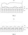
- the patient support device 100 comprises first air cells 101, second air cells 102 and third air cells 103.
- a recumbent person 200 such as a patient, imposes his or her body weight on the patient support device 100, whereas the patient support device 100 provides a supporting force and causes variations in the supporting force.
- FIG. 3 there is shown a schematic view of the patient support device shown in FIG. 2 and operating in another state according to an embodiment of the present disclosure.
- second air cells 102 in the patient support device 100 are deflated, but third air cells 103 in the patient support device 100 are not deflated, such that alternating supporting forces are generated. Variations in the supporting forces preclude lengthy compression of the recumbent patients' skin and subcutaneous tissue.
- first air cells 101 are deflated to a certain extent after deflation of second air cells 102 or deflation of third air cells 103, so as to increase the distance by which the patient support device 100 can be pushed downward and enhance comfortableness of the patient support system.
- the passage below describes how to deflate first air cells 101.
- the air distribution device 300 is hereunder described first. Referring to FIG. 4 , there is shown a structural schematic view of an air distribution device according to an embodiment of the present disclosure.
- the air distribution device 300 comprises an air distribution dial 310, base 320, control element 330, upper pad 341, lower pad 342, resilient element 350, and motor 360.
- FIG. 4 shows only essential components but omits minor components, such as fastening components.
- the motor 360 has an axle and is connected to the air distribution dial 310 by the axle; thus, the rotating axle of the motor 360 drives the air distribution dial 310 and changes the angle of the air distribution dial 310, so as to effect the selection of air distribution modes.
- the resilient element 350 is, for example, a spring disposed below the base 320 and adapted to exert a resilient force under which the spring abuts against the base 320, such that the upper surface of the base 320 is close to the lower surface of the air distribution dial 310, so as to increase the airtightness between the base 320 and the air distribution dial 310.
- the upper pad 341 and the lower pad 342 are disposed above and below the resilient element 350, respectively, to limit the position of the resilient element 350 in operation.
- the control element 330 detects the rotational position of the air distribution dial 310; thus, the control host 500 shown in FIG. 1 can control the air distribution device 300, for example, adjust air distribution modes.
- control element 330 is a microswitch which operates in conjunction with a positioning element of the air distribution dial 310 to detect the rotational position of the air distribution dial 310, but the present disclosure is not limited thereto.
- control element 330 is an optical switch or any other switch.
- FIG. 5 is a structural schematic view of an air distribution dial and a base according to an embodiment of the present disclosure.
- FIG. 6 is a schematic view of segmentation of the base shown in FIG. 5 .
- the base 320 comprises a first hole 3211, a second hole 3212, a third hole 3213, an air supply hole 3214 and a deflation hole 3215, which are disposed on the upper surface of the base 320 and adapted to match the outline of the lower surface of the air distribution dial 310.
- the base 320 is designed to allow the first hole 3211 to be in communication with a first pipe 3211a, the second hole 3212 to be in communication with a second pipe 3212b, the third hole 3213 to be in communication with a third pipe 3213c, the air supply hole 3214 to be in communication with an air supply pipe 3214a, and the deflation hole 3215 to be in communication with a deflation pipe 3215a.
- the pipes are in communication with the holes on the upper surface of the base 320, respectively, such that all the gaseous passages lead to the base 320. This, coupled with the operation of the air distribution dial 310, achieves air distribution and thus effects the inflation and deflation processes of the air cells.
- FIG. 5 and FIG. 6 merely serve an exemplary purpose rather than restrictive purpose, and thus whatever communication structures are applicable to the embodiments of the present disclosure.
- the first pipe 3211a is connected to first air cells 101 (air cells A shown in FIG. 2 and FIG. 3 ) of the patient support device 100.
- the second pipe 3212b is connected to second air cells 102 (air cells B shown in FIG. 2 and FIG. 3 ) of the patient support device 100.
- the third pipe 3213c is connected to third air cells 103 (air cells C shown in FIG. 2 and FIG. 3 ) of the patient support device 100.
- the pipes are in communication with air cells through subsequent branch pipelines (not shown), respectively.
- air supply pipe 3214a is connected to air supply source 400 shown in FIG. 1
- the deflation pipe 3215a is connected to an appropriate air-discharging position.
- the air distribution dial 310 in this embodiment comprises an air admitting portion 312, a deflation portion 314 and a stop portion 316.
- the air admitting portion 312 has an air admitting channel 3123, first communication recess 3121, second communication recess 3122 and air distribution channel 3124.
- the deflation portion 314 has a deflation channel 3141 and deflation recess 3142.
- the stop portion 316 surrounds the air admitting channel 3123 and is disposed between the first communication recess 3121 and the second communication recess 3122.
- the top surface of the base 320 is divided into a first segment N1, a second segment N2, a third segment N3 and a fourth segment N4, which are annular and concentric outward from the center.
- the air supply hole 3214 is at the first segment N1.
- the first hole 3211 is at the second segment N2.
- the second hole 3212 and third hole 3213 are at the third segment N3.
- the deflation hole 3215 is at the fourth segment N4.
- first hole 3211 and the air supply hole 3214 are separated by first distance d1
- second hole 3212 and the air supply hole 3214 are separated by second distance d2
- the third hole 3213 and the air supply hole 3214 are separated by third distance d3
- the deflation hole 3215 and the air supply hole 3214 are separated by fourth distance d4.
- Both second distance d2 and third distance d3 are greater than first distance d1.
- first distance d1, second distance d2 and third distance d3 are less than fourth distance d4.
- second distance d2 is equal to third distance d3.
- the first hole 3211 is disposed between the second hole 3212 and the third hole 3213. All the holes described above in this embodiment serve an exemplary purpose and are conducive to setting subsequent air distribution modes.
- the first communication recess 3121 is connected to the air admitting channel 3123 and the air distribution channel 3124, whereas the second communication recess 3122 is connected to the air admitting channel 3123 but is not connected to the air distribution channel 3124.
- the air admitting channel 3123 corresponds in position to the first segment N1 of the base 320 (see FIG. 6 ).
- the first communication recess 3121, second communication recess 3122 and stop portion 316 correspond in position to the second segment N2 of the base 320 (see FIG. 6 ).
- the air distribution channel 3124 corresponds in position to the third segment N3 of the base 320 (see FIG. 6 ).
- the supply gas received by the air distribution device 300 is transferred, via the air supply hole 3214 corresponding in position to the first segment N1, to the air admitting channel 3123 so as to enter the air distribution region of the air distribution dial 310. After that, the gas is delivered from the first communication recess 3121 to a corresponding hole or the air distribution channel 3124 or from the second communication recess 3122 to a corresponding hole.
- the deflation recess 3142 and the air distribution channel 3124 are spaced apart. Furthermore, the deflation recess 3142 is connected to the deflation channel 3141. The deflation recess 3142 corresponds in position to the third segment N3 of the base 320. The deflation channel 3141 corresponds in position to the fourth segment N4 of the base 320. Therefore, with the air distribution dial 310 being set to different angles, gas is transferred to a corresponding region to thereby carry out the inflation and deflation processes of the air cells in various modes.
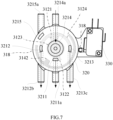
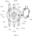
- FIG. 7 through FIG. 12 there are shown six schematic views of the respective air distribution modes according to an embodiment of the present disclosure.
- FIG. 7 through FIG. 12 depict the base 320 from above and show see-through outlines of the channels and communication recesses of the air distribution dial 310, so as to illustrate how to distribute air at different angles of the air distribution dial 310.
- the gas passages attained with the air distribution dial 310 are presented and distinguished in the form of sparsely distributed dots and densely distributed dots.
- Two positioning elements 318 are disposed on two opposing, lateral sides of the air distribution dial 310, respectively, and adapted to trigger the control element 330.
- the air distribution dial 310 is rotated to cause any one of the two positioning elements 318 to trigger the control element 330, thereby generating a specific signal.
- the specific signal can be set to a specific air distribution mode defined, for example, as follows: at this point in time, the air admitting channel 3123 is in communication with the first hole 3211, the second hole 3212 and the third hole 3213 simultaneously (See the description about the schematic views of air distribution modes below.)
- the air distribution dial 310 is set to the first angle.
- the first hole 3211 of the base 320 comes into communication with the air supply hole 3214 through the second communication recess 3122 and air admitting channel 3123 corresponding in position to the air distribution dial 310.
- the second hole 3212 of the base 320 comes into communication with the air supply hole 3214 through the air distribution channel 3124 and first communication recess 3121 corresponding in position to the air distribution dial 310.
- the third hole 3213 of the base 320 comes into communication with the air supply hole 3214 through the air distribution channel 3124 and first communication recess 3121 corresponding in position to the air distribution dial 310.
- the first hole 3211, the second hole 3212, and the third hole 3213 of the base 320 come into communication with the air supply hole 3214 of the base 320 through the air admitting portion 312 of the air distribution dial 310.
- the air distribution dial 310 which is set to the first angle enables the gas to be output from the first pipe 3211a, second pipe 3212b, and third pipe 3213c.
- the first air cells 101, second air cells 102 and third air cells 103 of the patient support device 100 are inflated in the (gas transfer) directions indicated by the arrows shown in FIG. 7 .
- the air distribution dial 310 is driven by the motor 360 (shown in FIG. 4 ) clockwise and set to a second angle.
- the first hole 3211 of the base 320 is closed by the stop portion 316 (shown in FIG. 5 ), such that the first hole 3211 corresponding in position to the first air cells 101 of the patient support device 100 cannot come into communication with any one of the second hole 3212, the third hole 3213, the air supply hole 3214 and the deflation hole 3215.
- the third hole 3213 of the base 320 can still be in communication with the air supply hole 3214 through the air distribution channel 3124 and first communication recess 3121.
- the second hole 3212 of the base 320 is in communication with the deflation hole 3215 through the deflation recess 3142 and deflation channel 3141.
- the second air cells 102 (air cells B shown in FIG. 2 and FIG. 3 ) of the patient support device 100 are deflated in the (gas transfer) directions indicated by the arrows shown in FIG. 8 . Therefore, in the state of the second angle, first air cells 101 in communication with the first hole 3211 are not in communication with third air cells 103 in communication with the third hole 3213 when second air cells 102 of the patient support device 100 are deflated. In the state of the second angle, the extent of deflation of second air cells 102 is determined according to how long the state lasts (for example, a predetermined time period).
- the air distribution dial 310 is driven by the motor 360 (shown in FIG. 4 ) clockwise and set to exiting the second angle. Therefore, the second angle of the air distribution dial 310 enables second air cells 102 to be deflated.
- the air distribution mode is attained when the air distribution dial 310 is driven to continue to rotate clockwise and thus exit the second angle.
- the first hole 3211 of the base 320 is continuously closed by the stop portion 316 (shown in FIG. 5 ).
- the third hole 3213 of the base 320 can still be in communication with the air supply hole 3214 through the air distribution channel 3124 and first communication recess 3121.
- the second hole 3212 of the base 320 no longer corresponds in position to the deflation recess 3142, and the second hole 3212 is at the third segment N3 on the top surface of the base 320.
- the deflation channel 3141 corresponds in position to the fourth segment N4 of the base 320.
- the second hole 3212 cannot be in communication with the deflation channel 3141 directly but must be in communication with the deflation channel 3141 through the deflation recess 3142. Therefore, as shown in FIG. 8 and FIG. 9 , in an embodiment serving an exemplary purpose, as soon as the second hole 3212 stops being in communication with the deflation recess 3142, the second hole 3212 becomes closed, and thus second air cells 102 (air cells B shown in FIG. 2 and FIG. 3 ) corresponding in position to the second hole 3212 stop being deflated.
- the air distribution dial 310 is driven by the motor 360 (shown in FIG. 4 ) clockwise and set to a third angle.
- the first hole 3211 of the base 320 comes into communication with the air supply hole 3214 through the second communication recess 3122 and air admitting channel 3123.
- the second hole 3212 of the base 320 exits the closed state shown in FIG. 9 to come into communication with the air supply hole 3214 once again through the air distribution channel 3124 and first communication recess 3121.
- the third hole 3213 of the base 320 is continuously in communication with the air supply hole 3214 through the air distribution channel 3124 and first communication recess 3121.
- the first hole 3211, the second hole 3212 and the third hole 3213 of the base 320 come into communication with the air supply hole 3214 of the base 320 through the air admitting portion 312 of the air distribution dial 310, but the first air cells 101, second air cells 102 and third air cells 103 also come into communication with each other.
- the air distribution dial 310 which is set to the third angle enables the gas to be output from the first pipe 3211a, second pipe 3212b, and third pipe 3213c.
- the first air cells 101, second air cells 102 and third air cells 103 of the patient support device 100 are inflated in the (gas transfer) directions indicated by the arrows shown in FIG. 10 .
- the air distribution dial 310 is driven continuously by the motor 360 (shown in FIG. 4 ) clockwise and set to a fourth angle.
- the first hole 3211 of the base 320 is closed by the stop portion 316 (shown in FIG. 5 ), such that the first hole 3211 corresponding in position to the first air cells 101 of the patient support device 100 cannot come into communication with any one of the second hole 3212, the third hole 3213, the air supply hole 3214 and the deflation hole 3215.
- the second hole 3212 of the base 320 can still be in communication with the air supply hole 3214 through the air distribution channel 3124 and first communication recess 3121.
- the third hole 3213 of the base 320 is in communication with the deflation hole 3215 through the deflation recess 3142 and deflation channel 3141.
- FIG. 8 and FIG. 11 illustrate air distribution modes and serve exemplary purposes.
- FIG. 11 shows that the second hole 3212 or third hole 3213 is in communication with the deflation hole 3215 to effect the deflation of second air cells 102 (air cells B shown in FIG. 2 and FIG. 3 ) or third air cells 103 (air cells C shown in FIG. 2 and FIG. 3 ) of the patient support device 100, thereby achieving alternate inflation and deflation and reducing the chance that recumbent patients will develop pressure ulcers.
- the air distribution dial 310 is driven by the motor 360 (shown in FIG. 4 ) clockwise and set to exiting the fourth angle. Therefore, the fourth angle of the air distribution dial 310 enables third air cells 103 to be deflated.
- the air distribution mode illustrated by FIG. 12 is attained.
- the first hole 3211 of the base 320 is continuously closed by the stop portion 316 (shown in FIG. 5 ).
- the second hole 3212 of the base 320 can still be in communication with the air supply hole 3214 through the air distribution channel 3124 and first communication recess 3121.
- the third hole 3213 of the base 320 no longer corresponds in position to the deflation recess 3142, and the third hole 3213 is at the third segment N3 on the top surface of the base 320.
- the deflation channel 3141 corresponds in position to the fourth segment N4 of the base 320.
- the third hole 3213 cannot be in communication with the deflation channel 3141 directly but must be in communication with the deflation channel 3141 through the deflation recess 3142. Therefore, given the operating principle illustrated by FIG. 11 and FIG. 12 which serve exemplary purposes, once the third hole 3213 stops being in communication with the deflation recess 3142, the third hole 3213 becomes closed, and thus third air cells 103 (air cells C shown in FIG. 2 and FIG. 3 ) corresponding in position to the third hole 3213 stop being deflated.
- both the air distribution channel 3124 and deflation channel 3141 disposed on the air distribution dial 310 follow curved paths.
- the angle by which the deflation channel 3141 turns is greater than 180 degrees.
- the angle by which the air distribution channel 3124 turns is around 180 degrees. Therefore, the air distribution dial 310 rotates to attain different air distribution modes.
- FIG. 7 and FIG. 10 show that the air distribution dial 310 can be set to different angles (the first and third angles) in the same air distribution mode, and the two angles can differ by around 180 degrees.
- the positioning elements 318 arranged oppositely trigger the control element 330 to inform the control host 500 of the position of the air distribution dial 310 and enable the control host 500 to confirm the air distribution mode. For instance, when the air distribution dial 310 is rotated to cause any one of the two positioning elements 318 to trigger the control element 330, the air admitting channel 3123 comes into communication with the first hole 3211, the second hole 3212 and the third hole 3213 (shown in FIG. 7 and FIG. 10 ) simultaneously.
- the air distribution dial 310 when the air distribution dial 310 is rotated to cause the first communication recess 3121 or second communication recess 3122 to correspond in position to the first hole 3211, the first hole 3211 comes into communication with the second hole 3212 and third hole 3213 (shown in FIG. 7 and FIG. 10 ) simultaneously through the air distribution channel 3124.
- the deflation function of the second hole can be switched to the third hole.
- the embodiment of the present disclosure is effective in achieving the alternate inflation and deflation function of the patient support device 100, controlling lower air cells (air cells A shown in FIG. 2 and FIG. 3 ), and enhancing the comfortableness of the patient support system.
- the ordinal numbers "second" and "third” regarding the second hole and third hole are merely intended to illustrate this embodiment.
- the second hole and third hole can be swapped for each other; for example, the hole to become communicable first can be either the second hole or the third hole.
- the air distribution dial 310 in the embodiments of the present disclosure is disk-shaped to serve an exemplary purpose, but the present disclosure is not limited thereto.
- an air distribution dial in any form can work well, provided that it comes into communication with each hole to attain any one of the aforesaid air distribution modes.
- the first hole 3211, the second hole 3212, the third hole 3213, the air supply hole 3214, the deflation hole 3215, the first communication recess 3121, the second communication recess 3122 and the deflation recess 3142 each have a width (also known as allowance). Therefore, despite a possible angular variation within a specific range of angles, the air distribution dial 310 stays in the same air distribution mode rather than switches to another air distribution mode. As a result, the first to fourth angles can each vary by a range of degrees, for example, around 3-5 degrees.
- the first angle ranges from 358 degree to 2 degree
- the second angle ranges from 42 degree to 47 degree
- the third angle ranges from 178 degree to 182 degree.
- the first angle and the second angle differ by 42 degrees to 48 degrees
- the second angle and the third angle by 42 degrees to 48 degrees
- the third angle and the fourth angle by 42 degrees to 48 degrees.
- a control unit drives the air supply source 400 and the air distribution device 300 to exercise control over the air cells in the patient support device 100.
- the air distribution method comprises an inflation preparation process, an inflation process, a deflation process, and a stop deflating process.
- the air cells in the patient support device 100 operate in the respective air distribution modes to provide appropriate recumbent modes and enhance the comfortableness of the patient support system.
- FIG. 13 there is shown a flowchart of an air distribution method in an alternating mode according to an embodiment of the present disclosure.
- the control unit has to confirm the position of the air distribution dial 310 of the air distribution device 300 from the very beginning, and thus the air distribution method starts with step S100 to confirm the position of the air distribution dial 310, by rotating the air distribution dial 310 until any one of the positioning elements 318 triggers the control element 330. After that, the air distribution dial 310 is at the position shown in FIG. 7 or FIG. 10 .
- step S200 wait for pressure equilibrium.
- the inflation preparation process does not allow the air supply source 400 to transfer gas from the air supply pipe 3214a to the air distribution dial 310 but allows first air cells 101, second air cells 102 and third air cells 103 (shown in FIG. 2 and FIG. 3 ) to come into communication with each other and thus attain pressure equilibrium therebetween.
- the air distribution dial 310 still keeps the position shown in FIG. 7 or FIG. 10 .
- step S300 inflate to attain a predetermined level of internal pressure.
- the inflation process entails inflating the first air cells 101, second air cells 102 and third air cells 103 (shown in FIG. 2 and FIG. 3 ) which are in communication with each other until the first air cells 101, second air cells 102 and third air cells 103 attain a predetermined level of internal pressure.
- the inflation is stopped by stopping the air supply operation of the air supply source 400.
- the levels of the pressure in the air cells are detected with pressure sensors (not shown) disposed in the air cells or with pressure sensors (not shown) disposed at gas passages connected between the air distribution device 300 and air supply source 400 to effect communication therebetween.
- Step S400 involves performing a deflation process.
- the air distribution dial 310 is rotated until the second air cells 102 or third air cells 103 are deflated.
- the air distribution dial 310 is now at the position shown in FIG. 8 but is at the position shown in FIG. 7 before its rotation begins.
- the air distribution dial 310 is now at the position shown in FIG. 11 but is at the position shown in FIG. 10 before its rotation begins.
- FIG. 8 is about deflation of second air cells 102.
- FIG. 11 is about deflation of third air cells 103.
- step S500 rotate the air distribution dial to stop the deflation process, after a predetermined time period has elapsed.
- a stop deflating process is carried out, after second air cells 102 or third air cells 103 have been deflated for the predetermined time period, to rotate the air distribution dial 310 until second air cells 102 or third air cells 103 are no longer in communication with the deflation hole 3215.
- first air cells 101 are not deflated and are spaced apart from the air supply source 400. At this point in time, the air distribution dial 310 is at the position shown in FIG. 9 or FIG. 10 .
- step S 100 the process flow of the air distribution method goes back to step S 100 to continuously perform subsequent steps with a view to effecting the alternating mode.
- alternate inflation and deflation of the other air cells take place while the clockwise rotation of the air distribution dial 310 is underway, so as to effect the alternating mode continuously.
- the first hole 3211, the second hole 3212 and the third hole 3213 are in communication with each other, such that the first air cells 101, second air cells 102 and third air cells 103 come into communication with each other once again. Therefore, the deflated second air cells 102 or third air cells 103 are replenished with gas from the other air cells, and the replenishment speed depends on the recumbent patients' body weight imposed on the air cells, thereby allowing the first air cells 101, second air cells 102 and third air cells 103 to attain the same level of internal pressure.
- the first air cells 101 no longer have a constant internal pressure but vary in internal pressure by being in communication with the deflated second air cells 102 or third air cells 103 above. Therefore, the present disposure has advantages as follows: increased buffer space of the patient support device 100; enhanced comfortableness of the patient support system; and a low chance of bottom-out, which is rendered possible because the first air cells 101 still keeps part of the gas.
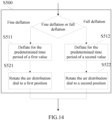
- FIG. 14 there is shown a flowchart of the air distribution method in a stop deflating process according to an embodiment of the present disclosure.
- the stop deflating process is carried out in either a fine deflation mode or a full deflation mode.
- the patients or caretakers set the fine deflation mode and the full deflation mode in advance according to different usage needs, such that the fine deflation mode or the full deflation mode can be carried out accordingly when the patient support system begins to perform the deflation process.
- the fine deflation mode is the choice.
- the full deflation mode will be the choice.
- step S500 includes step S511 and step S521.
- step S511 deflation lasts the predetermined time period of a first value, for example, 0 ⁇ 1 minute.
- step S521 the air distribution dial 310 is rotated to a first position. When the air distribution dial 310 is at the first position, the second air cells 102 or third air cells 103 are no longer in communication with the deflation hole 3215.
- step S500 includes step S512 and step S522.
- step S512 deflation lasts the predetermined time period of a second value, for example, 5 ⁇ 15 minutes.
- step S522 the air distribution dial 310 is rotated to a second position. When the air distribution dial 310 is at the second position, the second air cells 102 or third air cells 103 are no longer in communication with the deflation hole 3215.
- the first value is less than the second value. Therefore, the fine deflation mode enables second air cells 102 or third air cells 103 (but not both) to be deflated transiently and by an amount less than the full deflation mode does.
- the full deflation mode enables second air cells 102 or third air cells 103 (but not both) to be deflated to 1 atm, whereas the fine deflation mode enables second air cells 102 or third air cells 103 (but not both) to be deflated to an internal pressure level greater than 1 atm.
- the air distribution dial 310 is, in step S521, rotated to the first position as opposed to the second position in the full deflation mode.
- the first position can be the position shown in FIG. 9 or FIG. 12 which serves an exemplary purpose.
- the air distribution dial 310 is rotated to a position which differs from an initialized position by around 90 degrees (such as 85 to 95 degrees).
- the initialized position is the position at which the air distribution dial 310 enables the first hole 3211, the second hole 3212 and the third hole 3213 to be in communication with each other.
- the air distribution dial 310 When the air distribution dial 310 is at the first position, the air cells (second air cells 102 or third air cells 103) which have not been deflated can still be in communication with the air supply hole 3214 and thus can continuously receive gas from the air supply source 400. Consequently, in the fine deflation mode, variations which occur to the internal pressure of the air cells and are perceived by the recumbent patients are placed under good control, thereby further enhancing the comfortableness of the patient support system. Conversely, when the air distribution dial 310 is at the second position, i.e., corresponding to the state shown in FIG. 7 or FIG. 10 , the inflation preparation process begins immediately. Consequently, compared with the second position, the first position in the air distribution modes enables the recumbent patients to be less likely to perceive the difference arising from alternate inflation and deflation of the air cells, thereby further enhancing the comfortableness of the patient support system.
- Taiwan patent 1529508 discloses how to determine different, appropriate levels of pressure in accordance with the body weight of different patients in order to initialize a patient support system.
- the present disclosure provides an air distribution device and method applicable to a patient support system.
- the air distribution device comprises an air distribution dial and a base. Pressure variations of lower air cells can be effectuated on the air distribution dial, and the need for a fine deflation mode and full deflation mode can be met, thereby further enhancing the comfortableness of the patient support system.
Landscapes
- Health & Medical Sciences (AREA)
- Nursing (AREA)
- Life Sciences & Earth Sciences (AREA)
- Animal Behavior & Ethology (AREA)
- General Health & Medical Sciences (AREA)
- Public Health (AREA)
- Veterinary Medicine (AREA)
- Invalid Beds And Related Equipment (AREA)
Claims (13)
- Patientenlagerungssystem, welches Folgendes umfasst:eine Patientenlagerungsvorrichtung (100) mit ersten Luftzellen (101), zweiten Luftzellen (102), die über den ersten Luftzellen (101) angeordnet sind, und dritten Luftzellen (103), die über den ersten Luftzellen (101) angeordnet sind, undeine Luftverteilungsvorrichtung zur Verbindung mit einer Luftzufuhrquelle (400) und der Patientenlagerungsvorrichtung (100), wobei die Luftverteilungsvorrichtung Folgendes umfasst:eine Basis (320), die ein erstes Loch (3211), ein zweites Loch (3212), ein drittes Loch (3213), ein Luftzufuhrloch (3214) und ein Luftablassloch (3215) umfasst, wobei das erste Loch (3211) zur Verbindung mit den ersten Luftzellen (101) dient, das zweite Loch (3212) zur Verbindung mit den zweiten Luftzellen (102) dient, das dritte Loch (3213) zur Verbindung mit den dritten Luftzellen (103) dient, das Luftzufuhrloch (3214) zur Verbindung mit der Luftzufuhrquelle (400) dient und das Luftablassloch (3215) zum Ablassen von Luft verwendet wird, undeine Luftverteilungswählscheibe (310), die drehbar auf der Basis (320) angeordnet ist und einen Lufteinlassabschnitt (312), einen Ablassabschnitt (314) und einen Anschlagabschnitt (316) umfasst,dadurch gekennzeichnet, dasswenn die Luftverteilungswählscheibe (310) sich zu einem ersten Winkel dreht, das erste Loch (3211), das zweite Loch (3212) und das dritte Loch (3213) der Basis (320) mit dem Luftzufuhrloch (3214) der Basis (320) durch den Lufteinlassabschnitt (312) der Luftverteilungswählscheibe (310) in Verbindung kommen, so dass die ersten Luftzellen (101), die zweiten Luftzellen (102), die über den ersten Luftzellen (101) angeordnet sind, und die dritten Luftzellen (103), die über den ersten Luftzellen (101) angeordnet sind, miteinander in Verbindung kommen,wobei, wenn die Luftverteilungswählscheibe (310) sich zu einem zweiten Winkel dreht, das zweite Loch (3212) der Basis (320) in Verbindung mit dem Ablassloch (3215) der Basis (320) durch den Ablassabschnitt (314) der Luftverteilungswählscheibe (310) kommt, und der Anschlagabschnitt (316) der Luftverteilungsscheibe (310) das erste Loch (3211) der Basis (320) abdeckt, um zu verhindern, dass das erste Loch (3211) in Verbindung mit irgendeinem vom zweiten Loch (3212), vom dritten Loch (3213), vom Luftzufuhrloch (3214) und vom Ablassloch (3215) kommt, so dass die ersten Luftzellen (101), die mit dem ersten Loch (3211) in Verbindung stehen, nicht mit den dritten Luftzellen (103), die mit dem dritten Loch (3213) in Verbindung stehen, in Verbindung stehen, wenn die zweiten Luftzellen (102) der Patientenlagerungsvorrichtung (100) entleert sind.
- Patientenlagerungssystem nach Anspruch 1, wobei, nachdem sich die Luftverteilungswählscheibe (310) zum zweiten Winkel gedreht hat und für eine vorbestimmte Zeitdauer in dem zweiten Winkel geblieben ist, sich die Luftverteilungswählscheibe (310) zu einem dritten Winkel dreht, so dass das erste Loch (3211), das zweite Loch (3212) und das dritte Loch (3213) der Basis (320) mit dem Luftzufuhrloch (3214) der Basis (320) durch den Lufteinlassabschnitt (312) der Luftverteilungswählscheibe (310) in Verbindung kommen, wodurch die ersten Luftzellen (101), die zweiten Luftzellen (102) und die dritten Luftzellen (103) miteinander in Verbindung kommen können.
- Patientenlagerungssystem nach Anspruch 2, wobei der erste Winkel zwischen 358 und 2 Grad, der zweite Winkel zwischen 42 und 47 Grad und der dritte Winkel zwischen 178 und 182 Grad liegt.
- Patientenlagerungssystem nach Anspruch 1, wobei das erste Loch (3211) und das Luftzufuhrloch (3214) durch einen ersten Abstand (d1), das zweite Loch (3212) und das Luftzufuhrloch (3214) durch einen zweiten Abstand (d2) und das dritte Loch (3213) und das Luftzufuhrloch (3214) durch einen dritten Abstand (d3) voneinander getrennt sind, wobei sowohl der zweite Abstand (d2) als auch der dritte Abstand (d3) größer als der erste Abstand (d1) sind.
- Patientenlagerungssystem nach Anspruch 1, wobei das Ablassloch (3215) und das Luftzufuhrloch (3214) durch einen vierten Abstand (d4), das erste Loch (3211) und das Luftzufuhrloch (3214) durch einen ersten Abstand (d1), das zweite Loch (3212) und das Luftzufuhrloch (3214) durch einen zweiten Abstand (d2) und das dritte Loch (3213) und das Luftzufuhrloch (3214) durch einen dritten Abstand (d3) voneinander getrennt sind, wobei der erste Abstand (d1), der zweite Abstand (d2) und der dritte Abstand (d3) kleiner als der vierte Abstand (d4) sind.
- Patientenlagerungssystem nach Anspruch 4 oder 5, wobei der zweite Abstand (d2) dem dritten Abstand (d3) gleicht.
- Patientenlagerungssystem nach Anspruch 1, wobei eine obere Fläche der Basis (320) in ein erstes Segment (N1), ein zweites Segment (N2), ein drittes Segment (N3) und ein viertes Segment (N4), welche ringförmig und konzentrisch nach außen von der Mitte aus angeordnet sind, unterteilt ist, wobei das Luftzufuhrloch (3214) am ersten Segment (N1), das erste Loch (3211) am zweiten Segment (N2), das zweite und das dritte Loch (3212, 3213) am dritten Segment (N3) und das Ablassloch (3215) am vierten Segment (N4) angeordnet sind.
- Patientenlagerungssystem nach Anspruch 7, wobei die Luftverteilungswählscheibe (310) drehbar auf der oberen Fläche der Basis (320) angeordnet ist, wobei eine Fläche der Luftverteilungswählscheibe (310) der oberen Fläche der Basis (320) zugewandt ist und Folgendes aufweist:den Lufteinlassabschnitt (312), der einen Lufteinlasskanal (3123), eine erste Verbindungsaussparung (3121), eine zweite Verbindungsaussparung (3122) und einen Luftverteilungskanal (3124) aufweist, wobei die erste Verbindungsaussparung (3121) mit dem Lufteinlasskanal (3123) und dem Luftverteilungskanal verbunden ist und die zweite Verbindungsaussparung (3122) mit dem Lufteinlasskanal (3123), jedoch nicht mit dem Luftverteilungskanal, verbunden ist, wobei das erste Segment (N1) der Basis (320) in seiner Position dem Lufteinlasskanal (3123) entspricht, das zweite Segment (N2) der Basis (320) in seiner Position der ersten Verbindungsaussparung (3121) und der zweiten Verbindungsaussparung (3122) entspricht und das dritte Segment (N3) der Basis (320) in seiner Position dem Luftverteilungskanal (3124) entspricht,den Anschlagabschnitt (316), der zwischen der ersten Verbindungsaussparung (3121) und der zweiten Verbindungsaussparung (3122) angeordnet ist und in seiner Position dem zweiten Segment (N2) der Basis (320) entspricht, undden Ablassabschnitt (314), der einen Ablasskanal (3141) und eine Ablassaussparung (3142) aufweist, wobei der Ablasskanal (3141) in seiner Position dem vierten Segment (N4) entspricht und die Ablassaussparung (3142) vom Luftverteilungskanal (3124) beabstandet ist, mit dem Ablasskanal (3141) verbunden ist und in seiner Position dem dritten Segment (N3) der Basis (320) entspricht,wobei der Anschlagabschnitt (316) in Kontakt mit der oberen Fläche der Basis (320) kommt und somit das erste Loch (3211) verschließt, wenn die Luftverteilungswählscheibe (310) gedreht wird, um zu bewirken, dass der Anschlagabschnitt (316) über dem ersten Loch (3211) positioniert wird, und das erste Loch (3211) gleichzeitig mit dem zweiten Loch (3212) und dem dritten Loch (3213) durch den Luftverteilungskanal (3124) in Verbindung kommt, wenn die Luftverteilungswählscheibe (310) gedreht wird, um zu bewirken, dass die erste Verbindungsaussparung (3121) oder die zweite Verbindungsaussparung (3122) in ihrer Position dem ersten Loch (3211) entspricht.
- Patientenlagerungssystem nach Anspruch 1, welches ferner ein Steuerelement (330) und zwei Positionierungselemente (318) umfasst, die an zwei gegenüberliegenden seitlichen Flächen der Luftverteilungswählscheibe (310) angeordnet sind und dazu eingerichtet sind, das Steuerelement (330) auszulösen, wobei der Lufteinlasskanal (3123) gleichzeitig mit dem ersten Loch (3211), dem zweiten Loch und dem dritten Loch in Verbindung kommt, wenn die Luftverteilungswählscheibe gedreht wird, um zu bewirken, dass eines der beiden Positionierungselemente (318) das Steuerelement (330) auslöst.
- Patientenlagerungssystem nach Anspruch 1, wobei das erste Loch (3211) zwischen dem zweiten Loch (3212) und dem dritten Loch (3213) angeordnet ist.
- Luftverteilungsverfahren, das auf ein Patientenlagerungssystem nach einem der Ansprüche 1 bis 10 anwendbar ist, wobei eine Steuereinheit (500) verwendet wird, um eine Luftzufuhrquelle (400) und die Luftverteilungsvorrichtung (300) zu steuern, wobei das Luftverteilungsverfahren Folgendes umfasst:einen Aufblasvorbereitungsvorgang, um zu bewirken, dass die ersten Luftzellen (101), die zweiten Luftzellen (102) und die dritten Luftzellen (103) gleichzeitig miteinander in Verbindung kommen, wodurch ein Gleichgewicht des Innendrucks der ersten Luftzellen (101), der zweiten Luftzellen (102) und der dritten Luftzellen (103) erreicht wird,einen Aufblasvorgang zum Aufblasen der ersten Luftzellen (101), der zweiten Luftzellen (102) und der dritten Luftzellen (103) auf ein vorbestimmtes Niveau des Innendrucks,einen Luftablassvorgang zum Entleeren der zweiten Luftzellen (102) für eine vorbestimmte Zeitdauer, wobei die ersten Luftzellen (101) nicht entleert werden und von der Luftzufuhrquelle (400) beabstandet sind, undeinen Stopp-Ablass-Vorgang zum Stoppen der Entleerung der zweiten Luftzellen (102), wobei die ersten Luftzellen (101) nicht entleert werden und von der Luftzufuhrquelle (400) beabstandet sind.
- Luftverteilungsverfahren nach Anspruch 11, welches ferner einen feinen Luftablassmodus und einen vollständigen Luftablassmodus umfasst, wobei die vorbestimmte Zeitdauer des Luftablassvorgangs im feinen Luftablassmodus ein erster Wert ist und die vorbestimmte Zeitdauer des Luftablassvorgangs im vollständigen Luftablassmodus ein zweiter Wert ist, wobei der erste Wert kleiner als der zweite Wert ist, um eine vorübergehende Entleerung der zweiten Luftzellen oder der dritten Luftzellen im feinen Luftablassmodus mit einem geringeren Betrag als dem des vollständigen Luftablassmodus zu ermöglichen.
- Luftverteilungsverfahren nach Anspruch 11, welches ferner einen vollständigen Luftablassmodus umfasst, wobei die zweiten Luftzellen durch den Luftablassvorgang im vollständigen Luftablassmodus auf 1 atm entleert werden.
Applications Claiming Priority (1)
| Application Number | Priority Date | Filing Date | Title |
|---|---|---|---|
| TW108139591A TWI764059B (zh) | 2019-10-31 | 2019-10-31 | 應用於病患支撐系統的配氣裝置及配氣方法 |
Publications (2)
| Publication Number | Publication Date |
|---|---|
| EP3815664A1 EP3815664A1 (de) | 2021-05-05 |
| EP3815664B1 true EP3815664B1 (de) | 2024-10-30 |
Family
ID=72473370
Family Applications (1)
| Application Number | Title | Priority Date | Filing Date |
|---|---|---|---|
| EP20195548.1A Active EP3815664B1 (de) | 2019-10-31 | 2020-09-10 | Patientenlagerungssystem mit einer luftverteilungsvorrichtung und luftverteilungsverfahren für das patientenlagerungssystem |
Country Status (3)
| Country | Link |
|---|---|
| EP (1) | EP3815664B1 (de) |
| AU (1) | AU2020244416B1 (de) |
| TW (1) | TWI764059B (de) |
Families Citing this family (2)
| Publication number | Priority date | Publication date | Assignee | Title |
|---|---|---|---|---|
| CN114699257B (zh) * | 2022-04-11 | 2023-12-05 | 河北工业大学 | 一种基于气囊护理床垫小翻身运动的压疮预防方法 |
| EP4583835A4 (de) * | 2022-09-09 | 2026-01-07 | Hill Rom Services Inc | Verteileranordnung |
Citations (1)
| Publication number | Priority date | Publication date | Assignee | Title |
|---|---|---|---|---|
| WO2011021040A2 (en) * | 2009-08-19 | 2011-02-24 | Mjs Healthcare Limited | Inflatable support for therapeutic treatment and distributor device for controlling fluid supply thereto |
Family Cites Families (9)
| Publication number | Priority date | Publication date | Assignee | Title |
|---|---|---|---|---|
| GB8926213D0 (en) * | 1989-11-20 | 1990-01-10 | Pegasus Airwave Ltd | Air distributor |
| JPH04136575A (ja) * | 1990-09-25 | 1992-05-11 | Matsushita Electric Works Ltd | 流体ディストリビューター |
| TW373499U (en) * | 1998-10-09 | 1999-11-01 | Mei-Ting Lin | Air valve structure for the air cushion bed of 3 tubes alternative type |
| GB9826133D0 (en) * | 1998-11-27 | 1999-01-20 | Kci Medical Ltd | Rotary valve |
| GB2472819A (en) * | 2009-08-19 | 2011-02-23 | Mjs Healthcare Ltd | A support with a layer of inflatable cells wherein different groups of cells can simultaneously be inflated or deflated |
| US8156589B2 (en) * | 2009-09-17 | 2012-04-17 | Caremed Supply, Inc. | Air mattress |
| TWM424856U (en) * | 2011-11-02 | 2012-03-21 | Herbal Spirit Co Ltd | Air distribution plate structure of air bed |
| TWI516698B (zh) * | 2013-07-31 | 2016-01-11 | Apex Medical Corp | Air cushion device and its vent valve |
| TWI529508B (zh) * | 2014-10-13 | 2016-04-11 | Apex Medical Corp | Air cushion bed system, charge and discharge system and method |
-
2019
- 2019-10-31 TW TW108139591A patent/TWI764059B/zh active
-
2020
- 2020-09-10 EP EP20195548.1A patent/EP3815664B1/de active Active
- 2020-09-29 AU AU2020244416A patent/AU2020244416B1/en not_active Ceased
Patent Citations (1)
| Publication number | Priority date | Publication date | Assignee | Title |
|---|---|---|---|---|
| WO2011021040A2 (en) * | 2009-08-19 | 2011-02-24 | Mjs Healthcare Limited | Inflatable support for therapeutic treatment and distributor device for controlling fluid supply thereto |
Also Published As
| Publication number | Publication date |
|---|---|
| TW202118473A (zh) | 2021-05-16 |
| EP3815664A1 (de) | 2021-05-05 |
| AU2020244416B1 (en) | 2021-05-13 |
| TWI764059B (zh) | 2022-05-11 |
Similar Documents
| Publication | Publication Date | Title |
|---|---|---|
| US8296887B2 (en) | Resilient material/air bladder system | |
| US20080040860A1 (en) | Turn-assist with access areas | |
| EP2968047B1 (de) | Patiententragevorrichtung und -verfahren | |
| US6544203B2 (en) | Apparatus and method for continuous passive motion of the lumbar region | |
| EP3930654B1 (de) | Patientenpositionierungsvorrichtung und matratze | |
| US20260076853A1 (en) | Mattress system | |
| US20080092295A1 (en) | Vibrational and Pulsating Cushioning Device | |
| EP3815664A1 (de) | Luftverteilungsvorrichtung und -verfahren für ein patientenlagerungssystem | |
| WO2015124897A2 (en) | Improvements in and relating to cell inflation of a mattress | |
| EP0026799B1 (de) | Aufblasbarer Druckbehälter für pneumatische Massage | |
| KR101938209B1 (ko) | 에어 분배기 | |
| CN206434511U (zh) | 防褥疮的气动枕桥 | |
| JPH0354735Y2 (de) | ||
| CN211300807U (zh) | 一种防褥疮垫 | |
| AU2024278520B2 (en) | Support apparatus and method with shear relief | |
| US20250177233A1 (en) | System and method for simultaneously providing alternating low pressure therapy and skin cooling | |
| US11628110B2 (en) | Support apparatus and method with shear relief | |
| EP2467114A2 (de) | Aufblasbare stütze für therapeutische behandlung und verteilervorrichtung zur steuerung der flüssigkeitszufuhr dafür | |
| GB2432114A (en) | Pneumatic mattress | |
| TWM682164U (zh) | 氣墊床氣壓調整控制裝置 | |
| CN107928925A (zh) | 防褥疮的气动枕桥 | |
| TWM676703U (zh) | 具多閥體控制之氣壓床 | |
| GB2472819A (en) | A support with a layer of inflatable cells wherein different groups of cells can simultaneously be inflated or deflated | |
| GB2472818A (en) | A support with inflatable cells wherein the cells at one end have a smaller diameter | |
| HK1003320B (en) | A pressure controlled inflatable pad apparatus |
Legal Events
| Date | Code | Title | Description |
|---|---|---|---|
| PUAI | Public reference made under article 153(3) epc to a published international application that has entered the european phase |
Free format text: ORIGINAL CODE: 0009012 |
|
| STAA | Information on the status of an ep patent application or granted ep patent |
Free format text: STATUS: REQUEST FOR EXAMINATION WAS MADE |
|
| 17P | Request for examination filed |
Effective date: 20200930 |
|
| AK | Designated contracting states |
Kind code of ref document: A1 Designated state(s): AL AT BE BG CH CY CZ DE DK EE ES FI FR GB GR HR HU IE IS IT LI LT LU LV MC MK MT NL NO PL PT RO RS SE SI SK SM TR |
|
| RAP3 | Party data changed (applicant data changed or rights of an application transferred) |
Owner name: WELLELL INC. |
|
| STAA | Information on the status of an ep patent application or granted ep patent |
Free format text: STATUS: EXAMINATION IS IN PROGRESS |
|
| 17Q | First examination report despatched |
Effective date: 20230131 |
|
| GRAP | Despatch of communication of intention to grant a patent |
Free format text: ORIGINAL CODE: EPIDOSNIGR1 |
|
| STAA | Information on the status of an ep patent application or granted ep patent |
Free format text: STATUS: GRANT OF PATENT IS INTENDED |
|
| INTG | Intention to grant announced |
Effective date: 20240618 |
|
| GRAS | Grant fee paid |
Free format text: ORIGINAL CODE: EPIDOSNIGR3 |
|
| GRAA | (expected) grant |
Free format text: ORIGINAL CODE: 0009210 |
|
| STAA | Information on the status of an ep patent application or granted ep patent |
Free format text: STATUS: THE PATENT HAS BEEN GRANTED |
|
| AK | Designated contracting states |
Kind code of ref document: B1 Designated state(s): AL AT BE BG CH CY CZ DE DK EE ES FI FR GB GR HR HU IE IS IT LI LT LU LV MC MK MT NL NO PL PT RO RS SE SI SK SM TR |
|
| REG | Reference to a national code |
Ref country code: GB Ref legal event code: FG4D |
|
| REG | Reference to a national code |
Ref country code: CH Ref legal event code: EP |
|
| REG | Reference to a national code |
Ref country code: IE Ref legal event code: FG4D |
|
| REG | Reference to a national code |
Ref country code: DE Ref legal event code: R096 Ref document number: 602020040186 Country of ref document: DE |
|
| REG | Reference to a national code |
Ref country code: LT Ref legal event code: MG9D |
|
| REG | Reference to a national code |
Ref country code: NL Ref legal event code: MP Effective date: 20241030 |
|
| PG25 | Lapsed in a contracting state [announced via postgrant information from national office to epo] |
Ref country code: IS Free format text: LAPSE BECAUSE OF FAILURE TO SUBMIT A TRANSLATION OF THE DESCRIPTION OR TO PAY THE FEE WITHIN THE PRESCRIBED TIME-LIMIT Effective date: 20250228 Ref country code: HR Free format text: LAPSE BECAUSE OF FAILURE TO SUBMIT A TRANSLATION OF THE DESCRIPTION OR TO PAY THE FEE WITHIN THE PRESCRIBED TIME-LIMIT Effective date: 20241030 Ref country code: PT Free format text: LAPSE BECAUSE OF FAILURE TO SUBMIT A TRANSLATION OF THE DESCRIPTION OR TO PAY THE FEE WITHIN THE PRESCRIBED TIME-LIMIT Effective date: 20250228 |
|
| PG25 | Lapsed in a contracting state [announced via postgrant information from national office to epo] |
Ref country code: FI Free format text: LAPSE BECAUSE OF FAILURE TO SUBMIT A TRANSLATION OF THE DESCRIPTION OR TO PAY THE FEE WITHIN THE PRESCRIBED TIME-LIMIT Effective date: 20241030 Ref country code: NL Free format text: LAPSE BECAUSE OF FAILURE TO SUBMIT A TRANSLATION OF THE DESCRIPTION OR TO PAY THE FEE WITHIN THE PRESCRIBED TIME-LIMIT Effective date: 20241030 |
|
| REG | Reference to a national code |
Ref country code: AT Ref legal event code: MK05 Ref document number: 1736214 Country of ref document: AT Kind code of ref document: T Effective date: 20241030 |
|
| PG25 | Lapsed in a contracting state [announced via postgrant information from national office to epo] |
Ref country code: BG Free format text: LAPSE BECAUSE OF FAILURE TO SUBMIT A TRANSLATION OF THE DESCRIPTION OR TO PAY THE FEE WITHIN THE PRESCRIBED TIME-LIMIT Effective date: 20241030 |
|
| PG25 | Lapsed in a contracting state [announced via postgrant information from national office to epo] |
Ref country code: ES Free format text: LAPSE BECAUSE OF FAILURE TO SUBMIT A TRANSLATION OF THE DESCRIPTION OR TO PAY THE FEE WITHIN THE PRESCRIBED TIME-LIMIT Effective date: 20241030 |
|
| PG25 | Lapsed in a contracting state [announced via postgrant information from national office to epo] |
Ref country code: NO Free format text: LAPSE BECAUSE OF FAILURE TO SUBMIT A TRANSLATION OF THE DESCRIPTION OR TO PAY THE FEE WITHIN THE PRESCRIBED TIME-LIMIT Effective date: 20250130 |
|
| PG25 | Lapsed in a contracting state [announced via postgrant information from national office to epo] |
Ref country code: AT Free format text: LAPSE BECAUSE OF FAILURE TO SUBMIT A TRANSLATION OF THE DESCRIPTION OR TO PAY THE FEE WITHIN THE PRESCRIBED TIME-LIMIT Effective date: 20241030 Ref country code: LV Free format text: LAPSE BECAUSE OF FAILURE TO SUBMIT A TRANSLATION OF THE DESCRIPTION OR TO PAY THE FEE WITHIN THE PRESCRIBED TIME-LIMIT Effective date: 20241030 Ref country code: GR Free format text: LAPSE BECAUSE OF FAILURE TO SUBMIT A TRANSLATION OF THE DESCRIPTION OR TO PAY THE FEE WITHIN THE PRESCRIBED TIME-LIMIT Effective date: 20250131 |
|
| PG25 | Lapsed in a contracting state [announced via postgrant information from national office to epo] |
Ref country code: PL Free format text: LAPSE BECAUSE OF FAILURE TO SUBMIT A TRANSLATION OF THE DESCRIPTION OR TO PAY THE FEE WITHIN THE PRESCRIBED TIME-LIMIT Effective date: 20241030 |
|
| PG25 | Lapsed in a contracting state [announced via postgrant information from national office to epo] |
Ref country code: RS Free format text: LAPSE BECAUSE OF FAILURE TO SUBMIT A TRANSLATION OF THE DESCRIPTION OR TO PAY THE FEE WITHIN THE PRESCRIBED TIME-LIMIT Effective date: 20250130 |
|
| PG25 | Lapsed in a contracting state [announced via postgrant information from national office to epo] |
Ref country code: SM Free format text: LAPSE BECAUSE OF FAILURE TO SUBMIT A TRANSLATION OF THE DESCRIPTION OR TO PAY THE FEE WITHIN THE PRESCRIBED TIME-LIMIT Effective date: 20241030 |
|
| PG25 | Lapsed in a contracting state [announced via postgrant information from national office to epo] |
Ref country code: DK Free format text: LAPSE BECAUSE OF FAILURE TO SUBMIT A TRANSLATION OF THE DESCRIPTION OR TO PAY THE FEE WITHIN THE PRESCRIBED TIME-LIMIT Effective date: 20241030 |
|
| PG25 | Lapsed in a contracting state [announced via postgrant information from national office to epo] |
Ref country code: EE Free format text: LAPSE BECAUSE OF FAILURE TO SUBMIT A TRANSLATION OF THE DESCRIPTION OR TO PAY THE FEE WITHIN THE PRESCRIBED TIME-LIMIT Effective date: 20241030 |
|
| PGFP | Annual fee paid to national office [announced via postgrant information from national office to epo] |
Ref country code: FR Payment date: 20250521 Year of fee payment: 6 |
|
| PG25 | Lapsed in a contracting state [announced via postgrant information from national office to epo] |
Ref country code: RO Free format text: LAPSE BECAUSE OF FAILURE TO SUBMIT A TRANSLATION OF THE DESCRIPTION OR TO PAY THE FEE WITHIN THE PRESCRIBED TIME-LIMIT Effective date: 20241030 |
|
| PG25 | Lapsed in a contracting state [announced via postgrant information from national office to epo] |
Ref country code: SK Free format text: LAPSE BECAUSE OF FAILURE TO SUBMIT A TRANSLATION OF THE DESCRIPTION OR TO PAY THE FEE WITHIN THE PRESCRIBED TIME-LIMIT Effective date: 20241030 |
|
| PG25 | Lapsed in a contracting state [announced via postgrant information from national office to epo] |
Ref country code: CZ Free format text: LAPSE BECAUSE OF FAILURE TO SUBMIT A TRANSLATION OF THE DESCRIPTION OR TO PAY THE FEE WITHIN THE PRESCRIBED TIME-LIMIT Effective date: 20241030 |
|
| PG25 | Lapsed in a contracting state [announced via postgrant information from national office to epo] |
Ref country code: IT Free format text: LAPSE BECAUSE OF FAILURE TO SUBMIT A TRANSLATION OF THE DESCRIPTION OR TO PAY THE FEE WITHIN THE PRESCRIBED TIME-LIMIT Effective date: 20241030 |
|
| REG | Reference to a national code |
Ref country code: DE Ref legal event code: R097 Ref document number: 602020040186 Country of ref document: DE |
|
| PLBE | No opposition filed within time limit |
Free format text: ORIGINAL CODE: 0009261 |
|
| STAA | Information on the status of an ep patent application or granted ep patent |
Free format text: STATUS: NO OPPOSITION FILED WITHIN TIME LIMIT |
|
| PG25 | Lapsed in a contracting state [announced via postgrant information from national office to epo] |
Ref country code: SE Free format text: LAPSE BECAUSE OF FAILURE TO SUBMIT A TRANSLATION OF THE DESCRIPTION OR TO PAY THE FEE WITHIN THE PRESCRIBED TIME-LIMIT Effective date: 20241030 |
|
| 26N | No opposition filed |
Effective date: 20250731 |
|
| PGFP | Annual fee paid to national office [announced via postgrant information from national office to epo] |
Ref country code: GB Payment date: 20250701 Year of fee payment: 6 |
|
| PGFP | Annual fee paid to national office [announced via postgrant information from national office to epo] |
Ref country code: DE Payment date: 20250930 Year of fee payment: 6 |
|
| REG | Reference to a national code |
Ref country code: CH Ref legal event code: H13 Free format text: ST27 STATUS EVENT CODE: U-0-0-H10-H13 (AS PROVIDED BY THE NATIONAL OFFICE) Effective date: 20260504 |