EP3814581B1 - Rotational connections for stairs - Google Patents
Rotational connections for stairs Download PDFInfo
- Publication number
- EP3814581B1 EP3814581B1 EP19826208.1A EP19826208A EP3814581B1 EP 3814581 B1 EP3814581 B1 EP 3814581B1 EP 19826208 A EP19826208 A EP 19826208A EP 3814581 B1 EP3814581 B1 EP 3814581B1
- Authority
- EP
- European Patent Office
- Prior art keywords
- landing
- connection device
- configuration
- movement
- staircase
- Prior art date
- Legal status (The legal status is an assumption and is not a legal conclusion. Google has not performed a legal analysis and makes no representation as to the accuracy of the status listed.)
- Active
Links
Images





Classifications
-
- E—FIXED CONSTRUCTIONS
- E04—BUILDING
- E04B—GENERAL BUILDING CONSTRUCTIONS; WALLS, e.g. PARTITIONS; ROOFS; FLOORS; CEILINGS; INSULATION OR OTHER PROTECTION OF BUILDINGS
- E04B1/00—Constructions in general; Structures which are not restricted either to walls, e.g. partitions, or floors or ceilings or roofs
- E04B1/36—Bearings or like supports allowing movement
-
- E—FIXED CONSTRUCTIONS
- E04—BUILDING
- E04B—GENERAL BUILDING CONSTRUCTIONS; WALLS, e.g. PARTITIONS; ROOFS; FLOORS; CEILINGS; INSULATION OR OTHER PROTECTION OF BUILDINGS
- E04B1/00—Constructions in general; Structures which are not restricted either to walls, e.g. partitions, or floors or ceilings or roofs
- E04B1/62—Insulation or other protection; Elements or use of specified material therefor
- E04B1/92—Protection against other undesired influences or dangers
- E04B1/98—Protection against other undesired influences or dangers against vibrations or shocks; against mechanical destruction, e.g. by air-raids
-
- E—FIXED CONSTRUCTIONS
- E04—BUILDING
- E04F—FINISHING WORK ON BUILDINGS, e.g. STAIRS, FLOORS
- E04F11/00—Stairways, ramps, or like structures; Balustrades; Handrails
- E04F11/02—Stairways; Layouts thereof
- E04F11/022—Stairways; Layouts thereof characterised by the supporting structure
-
- E—FIXED CONSTRUCTIONS
- E04—BUILDING
- E04H—BUILDINGS OR LIKE STRUCTURES FOR PARTICULAR PURPOSES; SWIMMING OR SPLASH BATHS OR POOLS; MASTS; FENCING; TENTS OR CANOPIES, IN GENERAL
- E04H9/00—Buildings, groups of buildings or shelters adapted to withstand or provide protection against abnormal external influences, e.g. war-like action, earthquake or extreme climate
- E04H9/02—Buildings, groups of buildings or shelters adapted to withstand or provide protection against abnormal external influences, e.g. war-like action, earthquake or extreme climate withstanding earthquake or sinking of ground
- E04H9/021—Bearing, supporting or connecting constructions specially adapted for such buildings
Definitions
- the present invention generally relates to the field of stair systems. More specifically, embodiments provided herein relate to moveable stairs, including connectors, joints, devices, and configurations for allowing rotational, longitudinal, directional, and/or differential movements between levels or landings, and within stair structures to provide safe egress, enhance rescue, and/or reduce damage during movement.
- stairs are essential to not only providing a means for moving about the levels but also for providing safe egress out of the structure in the event of an emergency.
- stair safety is a constant concern as taller buildings continue to be constructed of new and more efficient materials and in various locations around the globe.
- the construction and installation of stairs create a necessary exit path that is regulated by various building codes which oftentimes require the stairs to survive fire and structural damage such that occupants can safely exit the building during a state of emergency.
- stair assemblies are rigidly connected to a landing or building structure rather than dynamically connected to a landing or building structure.
- typical stair assemblies do not allow for sufficient movement in the event of building motion (e.g ., during a seismic event, high winds, explosions, etc.).
- Rigidly connected stairs create a force that must be accounted for in the building design.
- rigidly connected stair systems can cause damage to any of the surrounding structure, the area below the stair system, and/or the stair system itself.
- Rigidly connected stairs can disconnect, crumble, fail, and/or fall during building motion, which prohibits occupants from safely exiting, delays rescue operations, and threatens safety.
- stair safety and installation can increase building safety and reduce the effects of building motion. Therefore, what is needed in the art is a moveable stair system and method. More specifically, what is needed is a rotational connection for stairs which allows for rotational movement, longitudinal movement, multidirectional movement, and/or orbital capacity to absorb landing displacement thus reducing damage to the stairs.
- the present invention relates to systems for allowing stair movement, including rotational movement, between building levels while maintaining the structural integrity of the stair system for safe egress passage.
- the systems and methods of the present disclosure allow for independent movement of the surrounding building walls, landings, floor slabs, and/or any other portion of the surrounding building structure or stair system.
- the embodiments of the present disclosure are suitable for use in both new constructions as well as in existing constructions for retrofit applications to allow for movement between levels, landings, or within stairwell structures.
- the embodiments of the present disclosure apply to both single and double stringer stairs.
- the present disclosure can reduce stair damage during building movement whether it is from wind, thermal, explosive, or seismic activity, and/or any other type of suitable force or experience, as the present disclosure allows at least for rotational movement and longitudinal movement, directional movement, or a combination thereof.
- an apparatus suitable for use with a stair system is defined in claim 1.
- the single-point connection device includes at least one of a shaft configuration, a pin-type configuration, a nut-and-bolt configuration, a ball-and-socket configuration, a hitch-type configuration, a ball-joint-rod-end configuration, a swivel joint configuration, or a configuration in which one or more structural shapes fit together.
- the secondary movement connection device comprises a first face having a slot therein, and, in some embodiments, the single-point connection device is at least partially disposed through the slot to operatively connect the secondary movement connection device with the single-point connection device. In some embodiments, the single-point connection device is centrally located within the first face.
- a moveable stair system is defined in claim 9.
- the secondary movement connection device includes a slotted connector, a track system connector, a guide rail connector, a wheeled connector, a roller connector, a slide connector, or a plate connector.
- the moveable stair system also includes a landing plate configured to cover a gap disposed between the staircase and a first landing.
- the first landing connection system is further operatively connected to a first landing.
- the present invention generally relates to stair systems and methods for allowing stair movement, including rotational movement, between building levels while maintaining the structural integrity of the stair system for safe egress passage.
- the systems and methods of the present disclosure allow for independent movement of the surrounding building walls, landings, floor slabs, and/or any other portion of the surrounding building structure or stair system.
- the embodiments of the present disclosure are suitable for use in both new constructions as well as in existing constructions for retrofit applications to allow for movement between levels, landings, or within stairwell structures.
- the embodiments of the present disclosure apply to both single and double stringer stairs; a double stringer embodiment is used in the accompanying drawings for purposes of illustration only.
- stair or "stairs” means a series of risers and treads adjacent to or between stringers.
- stairs or “staircase” further includes the definition, meaning, and use of the term “stair assembly.”
- the present disclosure can reduce stair damage during building movement whether it is from wind, thermal, explosive, seismic activity, and/or any other type of suitable force or experience, as the present disclosure allows for rotational movement, longitudinal movement, or a combination thereof.
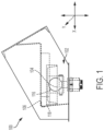
- Figures 1 , 2 , and 3 each schematically illustrate a first landing connection system 102 of a stair system 100.
- the first landing connection system 102 is disposed between a stair or staircase 106 and a landing 108.
- the landing 108 is an upper landing, while in other embodiments the landing 108 is a lower landing.
- a first landing connection system 102 can be operatively connected with an upper landing and a lower landing.
- the first landing connection system 102 includes a single-point connection device 104.
- the single point connection device 104 can include any of, by way of example only, a shaft configuration, a pin-type configuration, a nut-and-bolt configuration, a ball-and-socket configuration, a pin-type configuration, a ball-joint-rod-end configuration, a swivel joint configuration, a configuration in which one or more structural shapes fit together, or any other suitable configuration which provides for a single point connection.
- the single-point connection device 104 Upon connection with a stair or staircase 106, the single-point connection device 104 allows for rotational movement.
- the rotational movement includes movement in an X-direction and in a Y-direction.
- movement in the X-direction is movement in the transverse direction or side-to-side movement.
- movement in the Y-direction is movement in the longitudinal direction or back-and-forth movement.
- the single-point connection device 104 can include a coupler 116 and a cross channel 118.
- the cross channel 118 is disposed adjacent the single-point connection device 104.
- the coupler 116 and the cross channel 118 can operatively connect the first landing connection system 102 with the landing 108 and/or staircase 106.
- the cross channel 118 is U-shaped, however, any suitable shape can be utilized.
- the coupler 116 is a part of the single-point connection device 104 and receives the mating end of the single-point connection device 104.
- a positive connection is made via a pin configured to secure a ball into an acceptor. The pin, ball, and acceptor accommodate rotation and push the X and Y movements to the opposing connection.
- the first landing connection system 102 includes a base plate 110 for connection with the landing 108, as shown in Figures 2 and 3 , for example. Connection with the landing 108 can be made via any suitable connections means, for example, a bolted means. In some embodiments, one or more extenders 112 extend in an outward direction from the baseplate 110. As further shown in Figures 2 and 3 , by way crossbar 114 extends between the one or more extenders 112. The crossbar 114 includes a midpoint C. The single-point connection device 104 is centrally located proximate midpoint C within the first landing connection system 102.
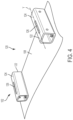
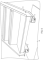
- Figures 4 , 5 , and 6 each schematically illustrate a second landing connection system 120 of the stair system 100.
- the second landing connection system includes at least one secondary movement connection device 122.
- the secondary movement connection device 122 includes a first face 124 with a slot 126 therethrough.
- the secondary movement connection device 122 is configured to be operatively connected with a stair or staircase 106 via any suitable connection, for example, a bolted connection.
- the secondary movement connection device 122 is configured for longitudinal movement in at least one direction, for example, in at least one of the X-direction and the Y-direction.
- movement in the X-direction is movement in the transverse direction, or side-to-side movement
- movement in the Y-direction is movement in the longitudinal direction, or back-and-forth movement.
- the staircase upon connection of the staircase 106 with the secondary movement connection device 122, the staircase is moveable in the longitudinal direction upon application of a force thereon.
- the at least one secondary movement connection device 122 includes a slotted connector, a track system connector, a guide rail connector, a wheeled connector, a roller connector, a slide connector, or a plate connector.
- Figure 7A schematically illustrates the stair system 100.
- the first landing connection system 102 shown in phantom, operatively connects an upper landing 202 with a staircase 206.
- the second landing connection system 120 shown in phantom in Figure 7B , operatively connects a lower landing 204 with the staircase 206.
- the first landing connection system 102 can operatively connect the lower landing 204 with the staircase 206
- the second landing connection 120 can operatively connect the upper landing 202 with the staircase 206.
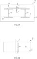
- Figures 8A and 8B each schematically illustrate features of a stair system 300.
- the stair system 300 includes a first landing connection system 302.
- the first landing connection system 302 is disposed between a stair or staircase and a landing.
- the landing is an upper landing, while in other embodiments the landing is a lower landing.
- a first landing connection system 302 can be operatively connected with an upper landing and a lower landing.
- the first landing connection system 302 can be operatively connected with a single landing whether it be an upper landing or a lower landing.
- the first landing connection system 302 includes a single-point connection device 304.
- the single point connection device 304 can include any of, by way of example only, a shaft configuration, a pin-type configuration, a nut-and-bolt configuration, a ball-and-socket configuration, a pin-type configuration, a ball-joint-rod-end configuration, a swivel joint configuration, a configuration in which one or more structural shapes fit together, or any other suitable configuration which provides for a single point connection.
- the single-point connection device 304 Upon connection with a stair or staircase, the single-point connection device 304 allows for rotational movement.
- the rotational movement includes movement in an X-direction and in a Y-direction. In some embodiments, movement in the X-direction is movement in the transverse direction, or side-to-side movement, while movement in the Y-direction is movement in the longitudinal direction, or back-and-forth movement.
- the first landing connection system 302 can include a coupler or a cross channel, as described further herein for embodiments shown in Figure 1 .
- the cross channel is disposed adjacent the single-point connection device 304.
- the coupler and the cross channel can operatively connect the first landing connection system 302 with the landing and/or staircase.
- the cross channel is U-shaped, however, any suitable shape can be utilized.
- the first landing connection system 302 includes a base plate 310 for connection with the landing. Connection with the landing can be made via any suitable connections means, for example, a bolted means.
- one or more extenders 312 extend in an outward direction from the baseplate 310. As shown in Figure 8A , by way of example only, the one or more extenders 312 are I-beams.
- the first landing connection system 302 includes a secondary movement connection system 308.
- the secondary movement connection system 308 includes a crossbar 314.
- the crossbar 314 extends between the one or more extenders 312.
- the crossbar 314 is coupled with the one or more extenders 312, for example, via a bolted connection, a welded connection, or any other suitable connection means.
- the crossbar can be a face, plate, beam, rail, or any other suitable device.
- the crossbar 314 includes a midpoint C.
- the single-point connection device 304 is centrally located proximate midpoint C within the first landing connection system 302.
- the secondary movement connection device 308 also includes a first face 318 of the crossbar 314.
- the first face 318 includes a slot 316 therein.
- the slot 316 can extend through the first face 318 or through the crossbar 314.
- the slot 316 can extend in the longitudinal director, in the lateral direction, or in an approximately diagonal direction.
- the single-point connection device is at least partially disposed through the slot to operatively connect the secondary movement connection device 308 with the single-point connection device 304, such that the single point connection device 304 is configured to move in the direction of the slot 316.
- the staircase upon connection of a staircase with a landing via the stair system of Figures 8A and 8B , the staircase is moveable in a rotational direction-in a combination of an X-direction and a Y-direction-as well as in a longitudinal direction-in at least one of the X-direction and the Y-direction.
- movement in the X-direction is movement in the transverse direction, or side-to-side movement
- movement in the Y-direction is movement in the longitudinal direction, or back-and-forth movement.
- Figure 9 schematically illustrates a moveable stair system 330.
- the moveable stair system includes a staircase 332 having one or more stairs 334.
- the first landing connection system 302 as discussed with reference to Figures 8A and 8B , supra, is disposed at a first end 306 of the staircase 332, wherein the first end 306 is opposite a second end 338.
- the first landing connection system 302 is operatively connected with a first landing 336 via any suitable connection means.
- the first landing connection system 302 includes the single-point connection device 304 and the secondary movement connection device 308.
- the staircase 332 is operatively connected with the first single-point connection device 308.
- the first landing connection system 302 includes a landing plate.
- the landing plate is operatively disposed to cover a gap between the staircase 332 and the first landing 336.
- a second end 338 of the staircase 332 can rest on the landing or floor 340, or in other embodiments, the second end 338 of the staircase 332 can be operatively connected with the landing or floor 340 via any suitable connection means.
- Exemplary benefits of stair systems in accordance with the disclosed subject matter include that the stair system allows for rotational movement to absorb landing displacement reducing damage to the stair system, thus allowing for safe egress.
- the disclosed connection means for connecting a staircase with a landing allows for the staircase to rotate, thus accommodating interstory drift in response to an event causing the structure to shake or move (i.e., earthquake, high winds, explosions, etc.).
- the present disclosure allows stairs the freedom to move to reduce force transfers to unsupported areas of a building, to maintain the structural integrity of the stairs during and after an event to allow for safe egress of occupants and safe ingress of emergency services to later allow for reoccupation of the building.
- the stair systems disclosed are easily disposed at the top or bottom of a flight of stairs, thus allowing all movement to be located at one point (e.g., an intermediate landing) as opposed to requiring each axis of movement to be located at opposite ends of the flight.
- one end of the flight of stairs can remain fixed or free and yet still provide the benefits of rotational movement.
- testing has been performed and results indicate that, during movement events, stairs tend to naturally move in a rotational direction. As such, the rotational movement permitted by the systems of the present disclosure reduces the risk of damage not only to the stairs or building, but also to adjacent architecture and structural components.
- the stair systems and methods disclosed allow for stair movement between building levels, platforms, landings, or the like while maintaining the structural integrity of the stair system for safe egress passage.
- the systems and methods disclosed further allow for independent movement of the surrounding building walls, landings, floor slabs, and/or any other portion of the surrounding building structure to the stair system.
- the embodiments of the present disclosure are suitable for use in both new constructions as well as in existing constructions for retrofit applications to allow for movement between levels, landings, or within stairwell structures.
- the present invention can reduce stair damage during building movement whether it is from wind, thermal, or seismic activity, and/or any other type of suitable force or experience, as the present invention allows for rotational movement, longitudinal movement, directional movement, or a combination thereof.
Landscapes
- Engineering & Computer Science (AREA)
- Architecture (AREA)
- Civil Engineering (AREA)
- Structural Engineering (AREA)
- Environmental & Geological Engineering (AREA)
- Business, Economics & Management (AREA)
- Emergency Management (AREA)
- Physics & Mathematics (AREA)
- Electromagnetism (AREA)
- Steps, Ramps, And Handrails (AREA)
Description
- This application claims the benefit of priority of
U.S. Provisional Patent Application No. 62/691,058 filed June 28, 2018 - The present invention generally relates to the field of stair systems. More specifically, embodiments provided herein relate to moveable stairs, including connectors, joints, devices, and configurations for allowing rotational, longitudinal, directional, and/or differential movements between levels or landings, and within stair structures to provide safe egress, enhance rescue, and/or reduce damage during movement.
- In multi-level buildings and structures stairs are essential to not only providing a means for moving about the levels but also for providing safe egress out of the structure in the event of an emergency. As such, stair safety is a constant concern as taller buildings continue to be constructed of new and more efficient materials and in various locations around the globe. The construction and installation of stairs create a necessary exit path that is regulated by various building codes which oftentimes require the stairs to survive fire and structural damage such that occupants can safely exit the building during a state of emergency.
- Conventional stair assemblies, however, are rigidly connected to a landing or building structure rather than dynamically connected to a landing or building structure. As such, typical stair assemblies do not allow for sufficient movement in the event of building motion (e.g., during a seismic event, high winds, explosions, etc.). Rigidly connected stairs create a force that must be accounted for in the building design. Furthermore, due to the interstory drift that occurs during building motion, rigidly connected stair systems can cause damage to any of the surrounding structure, the area below the stair system, and/or the stair system itself. Rigidly connected stairs can disconnect, crumble, fail, and/or fall during building motion, which prohibits occupants from safely exiting, delays rescue operations, and threatens safety. Moreover, due to interstory drift and the forces generated through a building during building motion, rigidly connected stairs may cause damage to themselves and the surrounding structure, thus causing the structure to perform differently than originally engineered. The results can further include structural damage surrounding the stairs, or partial or total collapse of the stairs. Any damage to and/or collapse of the stair system immediately eliminates a means of egress from the building and places the occupants therein in additional danger during or after a building motion event and/or emergency. Injury or loss of life is also possible depending on the extent of the damage.
- Moreover, attempts to solve these problems have been made, but many do not complete full-scale testing, or meet applicable building codes, regulations, and/or project requirements. Prior systems also are not designed or intended to accommodate rotation of the stairs during building movement.
US 2016/102461 A1 discloses a stair expansion joint system with freedom of movement between landings.WO 2018/212956 A1 discloses moveable stair systems and methods. - Thus, stair safety and installation can increase building safety and reduce the effects of building motion. Therefore, what is needed in the art is a moveable stair system and method. More specifically, what is needed is a rotational connection for stairs which allows for rotational movement, longitudinal movement, multidirectional movement, and/or orbital capacity to absorb landing displacement thus reducing damage to the stairs.
- The present invention relates to systems for allowing stair movement, including rotational movement, between building levels while maintaining the structural integrity of the stair system for safe egress passage. The systems and methods of the present disclosure allow for independent movement of the surrounding building walls, landings, floor slabs, and/or any other portion of the surrounding building structure or stair system. The embodiments of the present disclosure are suitable for use in both new constructions as well as in existing constructions for retrofit applications to allow for movement between levels, landings, or within stairwell structures. Moreover, the embodiments of the present disclosure apply to both single and double stringer stairs. The present disclosure can reduce stair damage during building movement whether it is from wind, thermal, explosive, or seismic activity, and/or any other type of suitable force or experience, as the present disclosure allows at least for rotational movement and longitudinal movement, directional movement, or a combination thereof.
- In accordance with the present invention, an apparatus suitable for use with a stair system is defined in
claim 1. - In some embodiments, the single-point connection device includes at least one of a shaft configuration, a pin-type configuration, a nut-and-bolt configuration, a ball-and-socket configuration, a hitch-type configuration, a ball-joint-rod-end configuration, a swivel joint configuration, or a configuration in which one or more structural shapes fit together. In certain embodiments, the secondary movement connection device comprises a first face having a slot therein, and, in some embodiments, the single-point connection device is at least partially disposed through the slot to operatively connect the secondary movement connection device with the single-point connection device. In some embodiments, the single-point connection device is centrally located within the first face.
- Also in accordance with the present invention, a moveable stair system is defined in claim 9.
- In some embodiments, the single-point connection device includes at least one of a shaft configuration, a pin-type configuration, a nut-and-bolt configuration, a ball-and-socket configuration, a hitch-type configuration, a ball-joint-rod-end configuration, a swivel joint configuration, or a configuration in which one or more structural shapes fit together. In certain embodiments, the secondary movement connection device includes a first face having a slot therein. The single-point connection device can at least be partially disposed through the slot to operatively connect the secondary movement connection device with the single-point connection device. In some embodiments, the single-point connection device is centrally located within the first face. In certain embodiments, the secondary movement connection device includes a slotted connector, a track system connector, a guide rail connector, a wheeled connector, a roller connector, a slide connector, or a plate connector. In some embodiments, the moveable stair system also includes a landing plate configured to cover a gap disposed between the staircase and a first landing. In certain embodiments, the first landing connection system is further operatively connected to a first landing.
- It is to be understood that both the foregoing general description and the following detailed description are exemplary and are intended to provide further explanation of the disclosed subject matter claimed.
- So that the manner in which the above recited features of the present disclosure can be understood in detail, a more particular description of the disclosure, briefly summarized above, can be had by reference to embodiments, some of which are illustrated in the appended drawings. It is to be noted, however, that the appended drawings illustrate only exemplary embodiments and the invention is defined by the claims.
-
Figure 1 schematically illustrates a side view of a first landing connection system of a stair system for allowing rotational movement of stairs, which can be used with the present invention. -
Figure 2 schematically illustrates a perspective view of a first landing connection system of a stair system for allowing rotational movement of stairs, which can be used with the present invention. -
Figure 3 schematically illustrates a side perspective view of the first landing connection system of the stair system for allowing rotational movement of stairs ofFigure 2 , which can be used with the present invention. -
Figure 4 schematically illustrates a perspective view of a second landing connection system of a stair system for allowing longitudinal movement of stairs, which can be used with the present invention. -
Figure 5 schematically illustrates a perspective view of a secondary movement connection device of the second landing connection system ofFigure 4 , which can be used with the present invention. -
Figure 6 schematically illustrates a staircase operatively connected with the second landing connection system ofFigure 4 , which can be used with the present invention. -
Figures 7A and 7B schematically illustrate perspective views of a staircase operatively connected with a stair system. -
Figure 8A schematically illustrates a front view of a first landing connection system of a stair system for allowing rotational movement and longitudinal movement of stairs, according to an embodiment of the present invention. -
Figure 8B schematically illustrates a top view of the first landing connection system ofFigure 8A . -
Figure 9 schematically illustrates a perspective view of a moveable stair system. - To facilitate understanding, identical reference numerals have been used to designate identical elements that are common to the figures. It is contemplated that elements and features of one embodiment can be beneficially incorporated in other embodiments without further recitation.
- The present invention generally relates to stair systems and methods for allowing stair movement, including rotational movement, between building levels while maintaining the structural integrity of the stair system for safe egress passage. The systems and methods of the present disclosure allow for independent movement of the surrounding building walls, landings, floor slabs, and/or any other portion of the surrounding building structure or stair system. The embodiments of the present disclosure are suitable for use in both new constructions as well as in existing constructions for retrofit applications to allow for movement between levels, landings, or within stairwell structures. Moreover, the embodiments of the present disclosure apply to both single and double stringer stairs; a double stringer embodiment is used in the accompanying drawings for purposes of illustration only. Furthermore, the term "stair" or "stairs" means a series of risers and treads adjacent to or between stringers. The term "stairs" or "staircase" further includes the definition, meaning, and use of the term "stair assembly." The present disclosure can reduce stair damage during building movement whether it is from wind, thermal, explosive, seismic activity, and/or any other type of suitable force or experience, as the present disclosure allows for rotational movement, longitudinal movement, or a combination thereof.
- Reference will now be made in detail to various exemplary embodiments of the invention, examples of which are illustrated in the accompanying drawings where
figures 8A and 8B show an embodiment of the invention andfigures 1 to 6 show further features of specific embodiments of the invention. The examples are not intended to limit the scope of the disclosed subject matter in any manner. The disclosed subject matter will be described in conjunction with the detailed description of the system. For purpose of illustration, and not limitation,Figures 1 ,2 , and3 each schematically illustrate a firstlanding connection system 102 of astair system 100. In some embodiments, the firstlanding connection system 102 is disposed between a stair orstaircase 106 and alanding 108. In some embodiments, the landing 108 is an upper landing, while in other embodiments thelanding 108 is a lower landing. In other embodiments, however, a firstlanding connection system 102 can be operatively connected with an upper landing and a lower landing. The firstlanding connection system 102 includes a single-point connection device 104. The singlepoint connection device 104 can include any of, by way of example only, a shaft configuration, a pin-type configuration, a nut-and-bolt configuration, a ball-and-socket configuration, a pin-type configuration, a ball-joint-rod-end configuration, a swivel joint configuration, a configuration in which one or more structural shapes fit together, or any other suitable configuration which provides for a single point connection. Upon connection with a stair orstaircase 106, the single-point connection device 104 allows for rotational movement. The rotational movement includes movement in an X-direction and in a Y-direction. In some embodiments, movement in the X-direction is movement in the transverse direction or side-to-side movement. In some embodiments, movement in the Y-direction is movement in the longitudinal direction or back-and-forth movement. - As further shown in
Figure 1 , the single-point connection device 104 can include acoupler 116 and across channel 118. Thecross channel 118 is disposed adjacent the single-point connection device 104. Thecoupler 116 and thecross channel 118 can operatively connect the firstlanding connection system 102 with thelanding 108 and/orstaircase 106. In some embodiments, thecross channel 118 is U-shaped, however, any suitable shape can be utilized. In some embodiments, thecoupler 116 is a part of the single-point connection device 104 and receives the mating end of the single-point connection device 104. In some embodiments, and by way of example only, a positive connection is made via a pin configured to secure a ball into an acceptor. The pin, ball, and acceptor accommodate rotation and push the X and Y movements to the opposing connection. - The first
landing connection system 102 includes abase plate 110 for connection with thelanding 108, as shown inFigures 2 and3 , for example. Connection with the landing 108 can be made via any suitable connections means, for example, a bolted means. In some embodiments, one ormore extenders 112 extend in an outward direction from thebaseplate 110. As further shown inFigures 2 and3 , byway crossbar 114 extends between the one ormore extenders 112. Thecrossbar 114 includes a midpoint C. The single-point connection device 104 is centrally located proximate midpoint C within the firstlanding connection system 102. - For purpose of illustration and not limitation,
Figures 4 ,5 , and6 each schematically illustrate a secondlanding connection system 120 of thestair system 100. In some embodiments, the second landing connection system includes at least one secondarymovement connection device 122. In some embodiments, the secondarymovement connection device 122 includes afirst face 124 with aslot 126 therethrough. The secondarymovement connection device 122 is configured to be operatively connected with a stair orstaircase 106 via any suitable connection, for example, a bolted connection. Further, in some embodiments, the secondarymovement connection device 122 is configured for longitudinal movement in at least one direction, for example, in at least one of the X-direction and the Y-direction. In some embodiments, movement in the X-direction is movement in the transverse direction, or side-to-side movement, while movement in the Y-direction is movement in the longitudinal direction, or back-and-forth movement. As such, upon connection of thestaircase 106 with the secondarymovement connection device 122, the staircase is moveable in the longitudinal direction upon application of a force thereon. - In some embodiments, the at least one secondary
movement connection device 122 includes a slotted connector, a track system connector, a guide rail connector, a wheeled connector, a roller connector, a slide connector, or a plate connector. -
Figure 7A schematically illustrates thestair system 100. As shown, the firstlanding connection system 102, shown in phantom, operatively connects anupper landing 202 with astaircase 206. Furthermore, the secondlanding connection system 120, shown in phantom inFigure 7B , operatively connects alower landing 204 with thestaircase 206. In certain embodiments, however, the firstlanding connection system 102 can operatively connect thelower landing 204 with thestaircase 206, and thesecond landing connection 120 can operatively connect theupper landing 202 with thestaircase 206. - For purpose of illustration and not limitation,
Figures 8A and 8B each schematically illustrate features of astair system 300. Thestair system 300 includes a firstlanding connection system 302. In some embodiments, the firstlanding connection system 302 is disposed between a stair or staircase and a landing. In some embodiments, the landing is an upper landing, while in other embodiments the landing is a lower landing. In certain embodiments, however, a firstlanding connection system 302 can be operatively connected with an upper landing and a lower landing. However, in some embodiments, the firstlanding connection system 302 can be operatively connected with a single landing whether it be an upper landing or a lower landing. The firstlanding connection system 302 includes a single-point connection device 304. The singlepoint connection device 304 can include any of, by way of example only, a shaft configuration, a pin-type configuration, a nut-and-bolt configuration, a ball-and-socket configuration, a pin-type configuration, a ball-joint-rod-end configuration, a swivel joint configuration, a configuration in which one or more structural shapes fit together, or any other suitable configuration which provides for a single point connection. Upon connection with a stair or staircase, the single-point connection device 304 allows for rotational movement. The rotational movement includes movement in an X-direction and in a Y-direction. In some embodiments, movement in the X-direction is movement in the transverse direction, or side-to-side movement, while movement in the Y-direction is movement in the longitudinal direction, or back-and-forth movement. - In some embodiments, the first
landing connection system 302 can include a coupler or a cross channel, as described further herein for embodiments shown inFigure 1 . The cross channel is disposed adjacent the single-point connection device 304. The coupler and the cross channel can operatively connect the firstlanding connection system 302 with the landing and/or staircase. In some embodiments, the cross channel is U-shaped, however, any suitable shape can be utilized. - In some embodiments, the first
landing connection system 302 includes abase plate 310 for connection with the landing. Connection with the landing can be made via any suitable connections means, for example, a bolted means. In some embodiments, one ormore extenders 312 extend in an outward direction from thebaseplate 310. As shown inFigure 8A , by way of example only, the one ormore extenders 312 are I-beams. In certain embodiments, the firstlanding connection system 302 includes a secondarymovement connection system 308. The secondarymovement connection system 308 includes acrossbar 314. Thecrossbar 314 extends between the one ormore extenders 312. In certain embodiments, thecrossbar 314 is coupled with the one ormore extenders 312, for example, via a bolted connection, a welded connection, or any other suitable connection means. In some embodiments, the crossbar can be a face, plate, beam, rail, or any other suitable device. Thecrossbar 314 includes a midpoint C. According to the invention, the single-point connection device 304 is centrally located proximate midpoint C within the firstlanding connection system 302. - As further illustrated in
Figure 8B , for the purpose of illustration and not limitation, the secondarymovement connection device 308 also includes afirst face 318 of thecrossbar 314. Thefirst face 318 includes aslot 316 therein. In some embodiments, theslot 316 can extend through thefirst face 318 or through thecrossbar 314. In certain embodiments, theslot 316 can extend in the longitudinal director, in the lateral direction, or in an approximately diagonal direction. In some embodiments, the single-point connection device is at least partially disposed through the slot to operatively connect the secondarymovement connection device 308 with the single-point connection device 304, such that the singlepoint connection device 304 is configured to move in the direction of theslot 316. As such, upon connection of a staircase with a landing via the stair system ofFigures 8A and 8B , the staircase is moveable in a rotational direction-in a combination of an X-direction and a Y-direction-as well as in a longitudinal direction-in at least one of the X-direction and the Y-direction. In some embodiments, movement in the X-direction is movement in the transverse direction, or side-to-side movement, while movement in the Y-direction is movement in the longitudinal direction, or back-and-forth movement. - For purpose of illustration and not limitation,
Figure 9 schematically illustrates amoveable stair system 330. The moveable stair system includes astaircase 332 having one ormore stairs 334. The firstlanding connection system 302 as discussed with reference toFigures 8A and 8B , supra, is disposed at afirst end 306 of thestaircase 332, wherein thefirst end 306 is opposite asecond end 338. In some embodiments, the firstlanding connection system 302 is operatively connected with afirst landing 336 via any suitable connection means. The firstlanding connection system 302 includes the single-point connection device 304 and the secondarymovement connection device 308. Thestaircase 332 is operatively connected with the first single-point connection device 308. In some embodiments, the firstlanding connection system 302 includes a landing plate. The landing plate is operatively disposed to cover a gap between thestaircase 332 and thefirst landing 336. In some embodiments, asecond end 338 of thestaircase 332 can rest on the landing orfloor 340, or in other embodiments, thesecond end 338 of thestaircase 332 can be operatively connected with the landing orfloor 340 via any suitable connection means. - Exemplary benefits of stair systems in accordance with the disclosed subject matter include that the stair system allows for rotational movement to absorb landing displacement reducing damage to the stair system, thus allowing for safe egress. Furthermore, the disclosed connection means for connecting a staircase with a landing allows for the staircase to rotate, thus accommodating interstory drift in response to an event causing the structure to shake or move (i.e., earthquake, high winds, explosions, etc.). The present disclosure allows stairs the freedom to move to reduce force transfers to unsupported areas of a building, to maintain the structural integrity of the stairs during and after an event to allow for safe egress of occupants and safe ingress of emergency services to later allow for reoccupation of the building. Additionally, the stair systems disclosed are easily disposed at the top or bottom of a flight of stairs, thus allowing all movement to be located at one point (e.g., an intermediate landing) as opposed to requiring each axis of movement to be located at opposite ends of the flight. As such, one end of the flight of stairs can remain fixed or free and yet still provide the benefits of rotational movement. Additionally, testing has been performed and results indicate that, during movement events, stairs tend to naturally move in a rotational direction. As such, the rotational movement permitted by the systems of the present disclosure reduces the risk of damage not only to the stairs or building, but also to adjacent architecture and structural components.
- The stair systems and methods disclosed allow for stair movement between building levels, platforms, landings, or the like while maintaining the structural integrity of the stair system for safe egress passage. The systems and methods disclosed further allow for independent movement of the surrounding building walls, landings, floor slabs, and/or any other portion of the surrounding building structure to the stair system. The
embodiments of the present disclosure are suitable for use in both new constructions as well as in existing constructions for retrofit applications to allow for movement between levels, landings, or within stairwell structures. The present invention can reduce stair damage during building movement whether it is from wind, thermal, or seismic activity, and/or any other type of suitable force or experience, as the present invention allows for rotational movement, longitudinal movement, directional movement, or a combination thereof. - While the foregoing is directed to embodiments described herein, other and further embodiments can be devised without departing from the scope of the present invention which is defined by the claims that follow.
Claims (15)
- An apparatus suitable for use in a stair system (300), comprising:
a first landing connection system (302) comprising:two or more extenders;a single-point connection device (304) configured to allow for rotational movement, wherein the rotational movement is movement in a combination of an X-direction and a Y-direction; anda secondary movement connection device (308) operatively connected with the single-point connection device (304) and configured for longitudinal movement in at least one of the X-direction and the Y-direction,wherein the secondary movement connection device (308) includes a crossbar (314) which extends between said two or more extenders (312), andwherein the single-point connection device is located proximate to a midpoint of the crossbar. - The apparatus of claim 1, wherein the single-point connection device (304) includes at least one of a shaft configuration, a pin-type configuration, a nut-and-bolt configuration, a ball-and-socket configuration, a hitch-type configuration, a ball-joint-rod-end configuration, a swivel joint configuration, or a configuration in which one or more structural shapes fit together.
- The apparatus of claim 2, wherein the crossbar of the secondary movement connection device (308) comprises a first face (318) having a slot (316) therein, and wherein the single-point connection device (304) is at least partially disposed through the slot (316) to operatively connect the secondary movement connection device (308) with the single-point connection device (304).
- The apparatus of claim 3, wherein the single-point connection device (304) is centrally located within the first face (318).
- The apparatus of claim 2, wherein the single-point connection device (304) further includes a coupler (116) and a cross channel (118), the coupler (116) and the cross channel (118) configured to operatively connect the first landing connection system (302) with a first landing (336) or a staircase (332) of the stair system (300).
- The apparatus of claim 1, further comprising a landing plate operatively connected to the first landing connection system (302) and configured to cover a gap disposed between a staircase (332) and a first landing (336).
- The apparatus of claim 1 and a first landing, wherein the first landing connection system (302) is further operatively connected to the first landing (336).
- The apparatus of claim 1, further comprising a second landing connection system (120).
- A moveable stair system (100), comprising:a staircase (206) having one or more stairs;an apparatus for use in a stair system according to claim 1 disposed at a first end of the staircase (206); anda second landing connection system (120) disposed at a second end of the staircase (206), wherein the second landing connection system (120) comprises a secondary movement connection device (122).
- The moveable stair system (100) of claim 9, wherein the single-point connection device (104) is centrally located within the first landing connection system (102).
- The moveable stair system (100) of claim 9, wherein the single-point connection device (104) includes at least one of a shaft configuration, a pin-type configuration, a nut-and-bolt configuration, a ball-and-socket configuration, a hitch-type configuration, a ball-joint-rod-end configuration, a swivel joint configuration, or a configuration in which one or more structural shapes fit together.
- The moveable stair system (100) of claim 11, wherein the single-point connection device (104) further includes a coupler (116) and a cross channel (118), wherein the coupler (116) and the cross channel (118) are configured to connect the single-point connection (104) device to the staircase (206).
- The moveable stair system (100) of claim 9, wherein the secondary movement connection device (122) includes a slotted connector, a track system connector, a guide rail connector, a wheeled connector, a roller connector, a slide connector, or a plate connector.
- The moveable stair system (100) of claim 9, a first landing (202) and a second landing (204), wherein the first landing connection system (102) is further operatively connected to the first landing (202), and wherein the second landing connection system (120) is further operatively connected to the second landing (204).
- The moveable stair system (100) of claim 9, further comprising a landing plate operatively connected to the first landing connection system and configured to cover a gap disposed between the staircase and a first landing.
Applications Claiming Priority (2)
| Application Number | Priority Date | Filing Date | Title |
|---|---|---|---|
| US201862691058P | 2018-06-28 | 2018-06-28 | |
| PCT/US2019/037023 WO2020005560A1 (en) | 2018-06-28 | 2019-06-13 | Rotational connections for stairs |
Publications (3)
| Publication Number | Publication Date |
|---|---|
| EP3814581A1 EP3814581A1 (en) | 2021-05-05 |
| EP3814581A4 EP3814581A4 (en) | 2022-06-15 |
| EP3814581B1 true EP3814581B1 (en) | 2025-05-21 |
Family
ID=68987548
Family Applications (1)
| Application Number | Title | Priority Date | Filing Date |
|---|---|---|---|
| EP19826208.1A Active EP3814581B1 (en) | 2018-06-28 | 2019-06-13 | Rotational connections for stairs |
Country Status (6)
| Country | Link |
|---|---|
| US (1) | US11332923B2 (en) |
| EP (1) | EP3814581B1 (en) |
| CA (1) | CA3104870A1 (en) |
| ES (1) | ES3031133T3 (en) |
| MX (1) | MX2021000118A (en) |
| WO (1) | WO2020005560A1 (en) |
Families Citing this family (1)
| Publication number | Priority date | Publication date | Assignee | Title |
|---|---|---|---|---|
| EP4219858B1 (en) * | 2017-05-15 | 2025-12-17 | EMEH, Inc. | Retrofit system for stairs |
Citations (1)
| Publication number | Priority date | Publication date | Assignee | Title |
|---|---|---|---|---|
| US4766708A (en) * | 1985-12-27 | 1988-08-30 | Peter Sing | Shock and vibration resistant structures |
Family Cites Families (35)
| Publication number | Priority date | Publication date | Assignee | Title |
|---|---|---|---|---|
| US2220155A (en) * | 1938-08-08 | 1940-11-05 | Jachim Frank | Folding stairway |
| US3299590A (en) * | 1964-06-01 | 1967-01-24 | Carter Lavoy | Prefabricated, adjustable stairway, ramp or bridge |
| US4039050A (en) * | 1969-05-13 | 1977-08-02 | Monsanto Company | Damping system |
| US3691712A (en) * | 1969-05-13 | 1972-09-19 | Monsanto Co | Damping system |
| US3626438A (en) * | 1969-12-15 | 1971-12-07 | Ozark Metal Products Inc | Adjustable stairs |
| US3693754A (en) * | 1971-03-16 | 1972-09-26 | Le Roy O Butler | Portable folding steps and landing for a mobile home and the like |
| US3946833A (en) * | 1973-12-13 | 1976-03-30 | Riehlmann Joseph F | Collapsible ladder suitable for use as fire escape |
| US3997026A (en) * | 1973-12-13 | 1976-12-14 | Riehlmann Joseph F | Collapsible ladder assembly suitable for use as fire escape |
| US3912298A (en) * | 1975-01-10 | 1975-10-14 | William D Humphrey | Foldable steps for mobile home |
| US4347638A (en) * | 1980-03-10 | 1982-09-07 | Weaver Murland L | Retractable porch and stair apparatus for trailers |
| US4642953A (en) * | 1986-02-10 | 1987-02-17 | Degood David A | Moveable stair apparatus |
| US4768617A (en) * | 1987-07-16 | 1988-09-06 | Wenger Corporation | Adjustable stairway having retractable wheel carriage |
| IT1222227B (en) * | 1988-04-01 | 1990-09-05 | Georgel Valentin Stanescu | SCALE FOR EMBARKING AND DISEMBARKING PASSENGERS FROM BOATS, WITH ACTUATING VEHICLES FOR POSITIONING AND WITHDRAWAL |
| US4959935A (en) * | 1989-09-25 | 1990-10-02 | Stob H Richard | Adjustable stairway |
| US5189854A (en) * | 1992-09-14 | 1993-03-02 | The United States Of America As Represented By The Secretary Of The Army | Adjustable height stairway |
| US6003270A (en) * | 1998-04-16 | 1999-12-21 | Macintyre; James R. | Variable riser seating system |
| US6868944B2 (en) * | 1998-05-21 | 2005-03-22 | Ez Stairs, Inc. | Adjustable stair stringer and railing |
| US6324795B1 (en) * | 1999-11-24 | 2001-12-04 | Ever-Level Foundation Systems, Inc. | Seismic isolation system between floor and foundation comprising a ball and socket joint and elastic or elastomeric element |
| US6527081B1 (en) * | 2001-05-30 | 2003-03-04 | Aluminum Ladder Company, | Embankment stairway |
| US6923140B1 (en) * | 2004-03-03 | 2005-08-02 | Aluminum Ladder Company | Boat access stairway |
| TW200809061A (en) | 2006-06-20 | 2008-02-16 | John Clement Preston | Stairway for use on building sites |
| US7967110B2 (en) * | 2006-07-27 | 2011-06-28 | Werner Co. | Tubular access ladder and method |
| US20080190049A1 (en) * | 2007-02-08 | 2008-08-14 | David Muti | Portable construction staircase |
| US7976746B2 (en) | 2007-03-26 | 2011-07-12 | Conservano Guy A | Method installing a modular concrete stair system |
| US20090300994A1 (en) | 2008-06-06 | 2009-12-10 | Atkins Iii Livingston Elwood | Removable stairway for an elevated platform and method |
| US8771544B2 (en) * | 2010-05-10 | 2014-07-08 | Larry James Hopper | Stair tower module |
| US8640826B1 (en) * | 2011-12-16 | 2014-02-04 | Richard R. Beilstein | Trailer rub rail portable ladder |
| US9290947B2 (en) * | 2012-07-31 | 2016-03-22 | Diamond Stairs Inc. | Stair systems and wall assemblies comprising same |
| ITTV20120171A1 (en) * | 2012-09-05 | 2014-03-06 | Daniele Pivetta | MODULE FOR CONSTRUCTION OF SELF-SUPPORTING MODULAR STAIRS WITH STEEL STRUCTURE |
| US9758981B2 (en) * | 2014-10-14 | 2017-09-12 | Emeh, Inc. | Stair expansion joint system with freedom of movement between landings |
| US9869084B2 (en) | 2014-10-14 | 2018-01-16 | Emeh, Inc. | Stair expansion joint system with freedom of movement between landings |
| ES2879866T3 (en) * | 2015-08-11 | 2021-11-23 | Zev Bianchi | Retractable ladder |
| US10640983B2 (en) * | 2016-03-23 | 2020-05-05 | Safe Rack Llc | Platform system |
| EP4219858B1 (en) * | 2017-05-15 | 2025-12-17 | EMEH, Inc. | Retrofit system for stairs |
| US10745919B1 (en) * | 2019-07-26 | 2020-08-18 | Big Time Investment, Llc | Method and apparatus for installing a staircase assembly into a building |
-
2019
- 2019-06-13 EP EP19826208.1A patent/EP3814581B1/en active Active
- 2019-06-13 ES ES19826208T patent/ES3031133T3/en active Active
- 2019-06-13 MX MX2021000118A patent/MX2021000118A/en unknown
- 2019-06-13 WO PCT/US2019/037023 patent/WO2020005560A1/en not_active Ceased
- 2019-06-13 US US17/255,983 patent/US11332923B2/en active Active
- 2019-06-13 CA CA3104870A patent/CA3104870A1/en active Pending
Patent Citations (1)
| Publication number | Priority date | Publication date | Assignee | Title |
|---|---|---|---|---|
| US4766708A (en) * | 1985-12-27 | 1988-08-30 | Peter Sing | Shock and vibration resistant structures |
Also Published As
| Publication number | Publication date |
|---|---|
| CA3104870A1 (en) | 2020-01-02 |
| US11332923B2 (en) | 2022-05-17 |
| EP3814581A1 (en) | 2021-05-05 |
| MX2021000118A (en) | 2021-03-09 |
| US20210115658A1 (en) | 2021-04-22 |
| WO2020005560A1 (en) | 2020-01-02 |
| NZ771746A (en) | 2024-10-25 |
| ES3031133T3 (en) | 2025-07-04 |
| EP3814581A4 (en) | 2022-06-15 |
Similar Documents
| Publication | Publication Date | Title |
|---|---|---|
| AU2023203238B2 (en) | Moveable stair systems and methods | |
| US6637580B1 (en) | Telescoping escalator seismic restraint | |
| KR101772362B1 (en) | A Great deep metro station structure | |
| RU2178376C2 (en) | Mobile platform | |
| US11332923B2 (en) | Rotational connections for stairs | |
| US11702855B1 (en) | Anti-seismic braced scissor stairs and frame stairs system | |
| US20020179368A1 (en) | Post-tensioned fall protection system | |
| US20090056243A1 (en) | Method and apparatus for retrofitting existing escalator systems | |
| JP2011017129A (en) | Universal handrail structure movable in horizontal two-dimensional direction | |
| NZ771746B2 (en) | Rotational connections for stairs | |
| RU2499742C2 (en) | Freight aircraft protective gear | |
| JP6692769B2 (en) | Passenger conveyor and installation method of passenger conveyor | |
| JP7464566B2 (en) | Structure | |
| CN220058973U (en) | Elevartor shaft protection system | |
| US11898341B2 (en) | Building core and kit for assembly | |
| CN218149353U (en) | Shock insulation stair structure | |
| CN220318360U (en) | Double-limb climbing formwork platform | |
| CN221742097U (en) | Lifeline system for high-altitude work on steel structures | |
| WO2011141945A1 (en) | Passenger conveyor | |
| CN109057391A (en) | It is a kind of for preventing the local stiffening structure of steel-frame structure continuous collapse | |
| CN120717319A (en) | Upper and lower shaft supporting devices with multiple functions to protect the safety of construction workers | |
| JP3757046B2 (en) | Passenger conveyor | |
| RU2307064C2 (en) | Device for mounting of load by means of flying vehicle | |
| CN119754497A (en) | Rapidly assembled prefabricated building and its staircase structure | |
| CN112012054A (en) | Suspension type monorail track beam installation operation platform and assembly method thereof |
Legal Events
| Date | Code | Title | Description |
|---|---|---|---|
| STAA | Information on the status of an ep patent application or granted ep patent |
Free format text: STATUS: THE INTERNATIONAL PUBLICATION HAS BEEN MADE |
|
| PUAI | Public reference made under article 153(3) epc to a published international application that has entered the european phase |
Free format text: ORIGINAL CODE: 0009012 |
|
| STAA | Information on the status of an ep patent application or granted ep patent |
Free format text: STATUS: REQUEST FOR EXAMINATION WAS MADE |
|
| 17P | Request for examination filed |
Effective date: 20210106 |
|
| AK | Designated contracting states |
Kind code of ref document: A1 Designated state(s): AL AT BE BG CH CY CZ DE DK EE ES FI FR GB GR HR HU IE IS IT LI LT LU LV MC MK MT NL NO PL PT RO RS SE SI SK SM TR |
|
| RIN1 | Information on inventor provided before grant (corrected) |
Inventor name: OSTOJIC, DARKO Inventor name: SMITH, KEVIN W. Inventor name: BELVIN, ROBERT J. Inventor name: PEACHY, ANTHONY J. |
|
| DAV | Request for validation of the european patent (deleted) | ||
| DAX | Request for extension of the european patent (deleted) | ||
| A4 | Supplementary search report drawn up and despatched |
Effective date: 20220513 |
|
| RIC1 | Information provided on ipc code assigned before grant |
Ipc: E04H 9/02 20060101ALI20220509BHEP Ipc: E04F 11/04 20060101ALI20220509BHEP Ipc: E04F 11/022 20060101ALI20220509BHEP Ipc: E04F 11/00 20060101ALI20220509BHEP Ipc: E04B 1/98 20060101ALI20220509BHEP Ipc: E04B 1/36 20060101AFI20220509BHEP |
|
| STAA | Information on the status of an ep patent application or granted ep patent |
Free format text: STATUS: EXAMINATION IS IN PROGRESS |
|
| 17Q | First examination report despatched |
Effective date: 20240326 |
|
| GRAP | Despatch of communication of intention to grant a patent |
Free format text: ORIGINAL CODE: EPIDOSNIGR1 |
|
| STAA | Information on the status of an ep patent application or granted ep patent |
Free format text: STATUS: GRANT OF PATENT IS INTENDED |
|
| INTG | Intention to grant announced |
Effective date: 20240927 |
|
| GRAJ | Information related to disapproval of communication of intention to grant by the applicant or resumption of examination proceedings by the epo deleted |
Free format text: ORIGINAL CODE: EPIDOSDIGR1 |
|
| STAA | Information on the status of an ep patent application or granted ep patent |
Free format text: STATUS: EXAMINATION IS IN PROGRESS |
|
| GRAP | Despatch of communication of intention to grant a patent |
Free format text: ORIGINAL CODE: EPIDOSNIGR1 |
|
| STAA | Information on the status of an ep patent application or granted ep patent |
Free format text: STATUS: GRANT OF PATENT IS INTENDED |
|
| INTC | Intention to grant announced (deleted) | ||
| INTG | Intention to grant announced |
Effective date: 20250107 |
|
| GRAS | Grant fee paid |
Free format text: ORIGINAL CODE: EPIDOSNIGR3 |
|
| GRAA | (expected) grant |
Free format text: ORIGINAL CODE: 0009210 |
|
| STAA | Information on the status of an ep patent application or granted ep patent |
Free format text: STATUS: THE PATENT HAS BEEN GRANTED |
|
| AK | Designated contracting states |
Kind code of ref document: B1 Designated state(s): AL AT BE BG CH CY CZ DE DK EE ES FI FR GB GR HR HU IE IS IT LI LT LU LV MC MK MT NL NO PL PT RO RS SE SI SK SM TR |
|
| REG | Reference to a national code |
Ref country code: GB Ref legal event code: FG4D |
|
| REG | Reference to a national code |
Ref country code: CH Ref legal event code: EP |
|
| REG | Reference to a national code |
Ref country code: DE Ref legal event code: R096 Ref document number: 602019070310 Country of ref document: DE |
|
| REG | Reference to a national code |
Ref country code: IE Ref legal event code: FG4D |
|
| REG | Reference to a national code |
Ref country code: ES Ref legal event code: FG2A Ref document number: 3031133 Country of ref document: ES Kind code of ref document: T3 Effective date: 20250704 |
|
| PGFP | Annual fee paid to national office [announced via postgrant information from national office to epo] |
Ref country code: DE Payment date: 20250627 Year of fee payment: 7 |
|
| PGFP | Annual fee paid to national office [announced via postgrant information from national office to epo] |
Ref country code: GB Payment date: 20250627 Year of fee payment: 7 |
|
| PGFP | Annual fee paid to national office [announced via postgrant information from national office to epo] |
Ref country code: FR Payment date: 20250625 Year of fee payment: 7 |
|
| REG | Reference to a national code |
Ref country code: NL Ref legal event code: MP Effective date: 20250521 |
|
| PG25 | Lapsed in a contracting state [announced via postgrant information from national office to epo] |
Ref country code: PT Free format text: LAPSE BECAUSE OF FAILURE TO SUBMIT A TRANSLATION OF THE DESCRIPTION OR TO PAY THE FEE WITHIN THE PRESCRIBED TIME-LIMIT Effective date: 20250922 Ref country code: FI Free format text: LAPSE BECAUSE OF FAILURE TO SUBMIT A TRANSLATION OF THE DESCRIPTION OR TO PAY THE FEE WITHIN THE PRESCRIBED TIME-LIMIT Effective date: 20250521 |
|
| PGFP | Annual fee paid to national office [announced via postgrant information from national office to epo] |
Ref country code: ES Payment date: 20250701 Year of fee payment: 7 |
|
| REG | Reference to a national code |
Ref country code: LT Ref legal event code: MG9D |
|
| PG25 | Lapsed in a contracting state [announced via postgrant information from national office to epo] |
Ref country code: NO Free format text: LAPSE BECAUSE OF FAILURE TO SUBMIT A TRANSLATION OF THE DESCRIPTION OR TO PAY THE FEE WITHIN THE PRESCRIBED TIME-LIMIT Effective date: 20250821 Ref country code: GR Free format text: LAPSE BECAUSE OF FAILURE TO SUBMIT A TRANSLATION OF THE DESCRIPTION OR TO PAY THE FEE WITHIN THE PRESCRIBED TIME-LIMIT Effective date: 20250822 |
|
| PG25 | Lapsed in a contracting state [announced via postgrant information from national office to epo] |
Ref country code: PL Free format text: LAPSE BECAUSE OF FAILURE TO SUBMIT A TRANSLATION OF THE DESCRIPTION OR TO PAY THE FEE WITHIN THE PRESCRIBED TIME-LIMIT Effective date: 20250521 Ref country code: NL Free format text: LAPSE BECAUSE OF FAILURE TO SUBMIT A TRANSLATION OF THE DESCRIPTION OR TO PAY THE FEE WITHIN THE PRESCRIBED TIME-LIMIT Effective date: 20250521 |
|
| PGFP | Annual fee paid to national office [announced via postgrant information from national office to epo] |
Ref country code: IT Payment date: 20250619 Year of fee payment: 7 |
|
| PG25 | Lapsed in a contracting state [announced via postgrant information from national office to epo] |
Ref country code: BG Free format text: LAPSE BECAUSE OF FAILURE TO SUBMIT A TRANSLATION OF THE DESCRIPTION OR TO PAY THE FEE WITHIN THE PRESCRIBED TIME-LIMIT Effective date: 20250521 |
|
| PG25 | Lapsed in a contracting state [announced via postgrant information from national office to epo] |
Ref country code: HR Free format text: LAPSE BECAUSE OF FAILURE TO SUBMIT A TRANSLATION OF THE DESCRIPTION OR TO PAY THE FEE WITHIN THE PRESCRIBED TIME-LIMIT Effective date: 20250521 |
|
| PG25 | Lapsed in a contracting state [announced via postgrant information from national office to epo] |
Ref country code: RS Free format text: LAPSE BECAUSE OF FAILURE TO SUBMIT A TRANSLATION OF THE DESCRIPTION OR TO PAY THE FEE WITHIN THE PRESCRIBED TIME-LIMIT Effective date: 20250821 |
|
| PG25 | Lapsed in a contracting state [announced via postgrant information from national office to epo] |
Ref country code: IS Free format text: LAPSE BECAUSE OF FAILURE TO SUBMIT A TRANSLATION OF THE DESCRIPTION OR TO PAY THE FEE WITHIN THE PRESCRIBED TIME-LIMIT Effective date: 20250921 |
|
| PG25 | Lapsed in a contracting state [announced via postgrant information from national office to epo] |
Ref country code: LV Free format text: LAPSE BECAUSE OF FAILURE TO SUBMIT A TRANSLATION OF THE DESCRIPTION OR TO PAY THE FEE WITHIN THE PRESCRIBED TIME-LIMIT Effective date: 20250521 |
|
| REG | Reference to a national code |
Ref country code: AT Ref legal event code: MK05 Ref document number: 1796865 Country of ref document: AT Kind code of ref document: T Effective date: 20250521 |
|
| PG25 | Lapsed in a contracting state [announced via postgrant information from national office to epo] |
Ref country code: SM Free format text: LAPSE BECAUSE OF FAILURE TO SUBMIT A TRANSLATION OF THE DESCRIPTION OR TO PAY THE FEE WITHIN THE PRESCRIBED TIME-LIMIT Effective date: 20250521 Ref country code: DK Free format text: LAPSE BECAUSE OF FAILURE TO SUBMIT A TRANSLATION OF THE DESCRIPTION OR TO PAY THE FEE WITHIN THE PRESCRIBED TIME-LIMIT Effective date: 20250521 Ref country code: AT Free format text: LAPSE BECAUSE OF FAILURE TO SUBMIT A TRANSLATION OF THE DESCRIPTION OR TO PAY THE FEE WITHIN THE PRESCRIBED TIME-LIMIT Effective date: 20250521 |
|
| PG25 | Lapsed in a contracting state [announced via postgrant information from national office to epo] |
Ref country code: CZ Free format text: LAPSE BECAUSE OF FAILURE TO SUBMIT A TRANSLATION OF THE DESCRIPTION OR TO PAY THE FEE WITHIN THE PRESCRIBED TIME-LIMIT Effective date: 20250521 |
|
| PG25 | Lapsed in a contracting state [announced via postgrant information from national office to epo] |
Ref country code: EE Free format text: LAPSE BECAUSE OF FAILURE TO SUBMIT A TRANSLATION OF THE DESCRIPTION OR TO PAY THE FEE WITHIN THE PRESCRIBED TIME-LIMIT Effective date: 20250521 |
|
| PG25 | Lapsed in a contracting state [announced via postgrant information from national office to epo] |
Ref country code: SK Free format text: LAPSE BECAUSE OF FAILURE TO SUBMIT A TRANSLATION OF THE DESCRIPTION OR TO PAY THE FEE WITHIN THE PRESCRIBED TIME-LIMIT Effective date: 20250521 Ref country code: RO Free format text: LAPSE BECAUSE OF FAILURE TO SUBMIT A TRANSLATION OF THE DESCRIPTION OR TO PAY THE FEE WITHIN THE PRESCRIBED TIME-LIMIT Effective date: 20250521 |
|
| REG | Reference to a national code |
Ref country code: CH Ref legal event code: H13 Free format text: ST27 STATUS EVENT CODE: U-0-0-H10-H13 (AS PROVIDED BY THE NATIONAL OFFICE) Effective date: 20260127 |
|
| PG25 | Lapsed in a contracting state [announced via postgrant information from national office to epo] |
Ref country code: LU Free format text: LAPSE BECAUSE OF NON-PAYMENT OF DUE FEES Effective date: 20250613 |
|
| PG25 | Lapsed in a contracting state [announced via postgrant information from national office to epo] |
Ref country code: MC Free format text: LAPSE BECAUSE OF FAILURE TO SUBMIT A TRANSLATION OF THE DESCRIPTION OR TO PAY THE FEE WITHIN THE PRESCRIBED TIME-LIMIT Effective date: 20250521 |
|
| REG | Reference to a national code |
Ref country code: DE Ref legal event code: R097 Ref document number: 602019070310 Country of ref document: DE |
|
| REG | Reference to a national code |
Ref country code: BE Ref legal event code: MM Effective date: 20250630 |
|
| PLBE | No opposition filed within time limit |
Free format text: ORIGINAL CODE: 0009261 |
|
| STAA | Information on the status of an ep patent application or granted ep patent |
Free format text: STATUS: NO OPPOSITION FILED WITHIN TIME LIMIT |
|
| REG | Reference to a national code |
Ref country code: CH Ref legal event code: L10 Free format text: ST27 STATUS EVENT CODE: U-0-0-L10-L00 (AS PROVIDED BY THE NATIONAL OFFICE) Effective date: 20260402 |
|
| PG25 | Lapsed in a contracting state [announced via postgrant information from national office to epo] |
Ref country code: IE Free format text: LAPSE BECAUSE OF NON-PAYMENT OF DUE FEES Effective date: 20250613 |
|
| PG25 | Lapsed in a contracting state [announced via postgrant information from national office to epo] |
Ref country code: BE Free format text: LAPSE BECAUSE OF NON-PAYMENT OF DUE FEES Effective date: 20250630 |
|
| PG25 | Lapsed in a contracting state [announced via postgrant information from national office to epo] |
Ref country code: CH Free format text: LAPSE BECAUSE OF NON-PAYMENT OF DUE FEES Effective date: 20250630 |
|
| 26N | No opposition filed |
Effective date: 20260224 |