EP3814581B1 - Drehverbindungen für treppen - Google Patents
Drehverbindungen für treppen Download PDFInfo
- Publication number
- EP3814581B1 EP3814581B1 EP19826208.1A EP19826208A EP3814581B1 EP 3814581 B1 EP3814581 B1 EP 3814581B1 EP 19826208 A EP19826208 A EP 19826208A EP 3814581 B1 EP3814581 B1 EP 3814581B1
- Authority
- EP
- European Patent Office
- Prior art keywords
- landing
- connection device
- configuration
- movement
- staircase
- Prior art date
- Legal status (The legal status is an assumption and is not a legal conclusion. Google has not performed a legal analysis and makes no representation as to the accuracy of the status listed.)
- Active
Links
Images





Classifications
-
- E—FIXED CONSTRUCTIONS
- E04—BUILDING
- E04B—GENERAL BUILDING CONSTRUCTIONS; WALLS, e.g. PARTITIONS; ROOFS; FLOORS; CEILINGS; INSULATION OR OTHER PROTECTION OF BUILDINGS
- E04B1/00—Constructions in general; Structures which are not restricted either to walls, e.g. partitions, or floors or ceilings or roofs
- E04B1/36—Bearings or like supports allowing movement
-
- E—FIXED CONSTRUCTIONS
- E04—BUILDING
- E04B—GENERAL BUILDING CONSTRUCTIONS; WALLS, e.g. PARTITIONS; ROOFS; FLOORS; CEILINGS; INSULATION OR OTHER PROTECTION OF BUILDINGS
- E04B1/00—Constructions in general; Structures which are not restricted either to walls, e.g. partitions, or floors or ceilings or roofs
- E04B1/62—Insulation or other protection; Elements or use of specified material therefor
- E04B1/92—Protection against other undesired influences or dangers
- E04B1/98—Protection against other undesired influences or dangers against vibrations or shocks; against mechanical destruction, e.g. by air-raids
-
- E—FIXED CONSTRUCTIONS
- E04—BUILDING
- E04F—FINISHING WORK ON BUILDINGS, e.g. STAIRS, FLOORS
- E04F11/00—Stairways, ramps, or like structures; Balustrades; Handrails
- E04F11/02—Stairways; Layouts thereof
- E04F11/022—Stairways; Layouts thereof characterised by the supporting structure
-
- E—FIXED CONSTRUCTIONS
- E04—BUILDING
- E04H—BUILDINGS OR LIKE STRUCTURES FOR PARTICULAR PURPOSES; SWIMMING OR SPLASH BATHS OR POOLS; MASTS; FENCING; TENTS OR CANOPIES, IN GENERAL
- E04H9/00—Buildings, groups of buildings or shelters adapted to withstand or provide protection against abnormal external influences, e.g. war-like action, earthquake or extreme climate
- E04H9/02—Buildings, groups of buildings or shelters adapted to withstand or provide protection against abnormal external influences, e.g. war-like action, earthquake or extreme climate withstanding earthquake or sinking of ground
- E04H9/021—Bearing, supporting or connecting constructions specially adapted for such buildings
Definitions
- the present invention generally relates to the field of stair systems. More specifically, embodiments provided herein relate to moveable stairs, including connectors, joints, devices, and configurations for allowing rotational, longitudinal, directional, and/or differential movements between levels or landings, and within stair structures to provide safe egress, enhance rescue, and/or reduce damage during movement.
- stairs are essential to not only providing a means for moving about the levels but also for providing safe egress out of the structure in the event of an emergency.
- stair safety is a constant concern as taller buildings continue to be constructed of new and more efficient materials and in various locations around the globe.
- the construction and installation of stairs create a necessary exit path that is regulated by various building codes which oftentimes require the stairs to survive fire and structural damage such that occupants can safely exit the building during a state of emergency.
- stair assemblies are rigidly connected to a landing or building structure rather than dynamically connected to a landing or building structure.
- typical stair assemblies do not allow for sufficient movement in the event of building motion (e.g ., during a seismic event, high winds, explosions, etc.).
- Rigidly connected stairs create a force that must be accounted for in the building design.
- rigidly connected stair systems can cause damage to any of the surrounding structure, the area below the stair system, and/or the stair system itself.
- Rigidly connected stairs can disconnect, crumble, fail, and/or fall during building motion, which prohibits occupants from safely exiting, delays rescue operations, and threatens safety.
- stair safety and installation can increase building safety and reduce the effects of building motion. Therefore, what is needed in the art is a moveable stair system and method. More specifically, what is needed is a rotational connection for stairs which allows for rotational movement, longitudinal movement, multidirectional movement, and/or orbital capacity to absorb landing displacement thus reducing damage to the stairs.
- the present invention relates to systems for allowing stair movement, including rotational movement, between building levels while maintaining the structural integrity of the stair system for safe egress passage.
- the systems and methods of the present disclosure allow for independent movement of the surrounding building walls, landings, floor slabs, and/or any other portion of the surrounding building structure or stair system.
- the embodiments of the present disclosure are suitable for use in both new constructions as well as in existing constructions for retrofit applications to allow for movement between levels, landings, or within stairwell structures.
- the embodiments of the present disclosure apply to both single and double stringer stairs.
- the present disclosure can reduce stair damage during building movement whether it is from wind, thermal, explosive, or seismic activity, and/or any other type of suitable force or experience, as the present disclosure allows at least for rotational movement and longitudinal movement, directional movement, or a combination thereof.
- an apparatus suitable for use with a stair system is defined in claim 1.
- the single-point connection device includes at least one of a shaft configuration, a pin-type configuration, a nut-and-bolt configuration, a ball-and-socket configuration, a hitch-type configuration, a ball-joint-rod-end configuration, a swivel joint configuration, or a configuration in which one or more structural shapes fit together.
- the secondary movement connection device comprises a first face having a slot therein, and, in some embodiments, the single-point connection device is at least partially disposed through the slot to operatively connect the secondary movement connection device with the single-point connection device. In some embodiments, the single-point connection device is centrally located within the first face.
- a moveable stair system is defined in claim 9.
- the secondary movement connection device includes a slotted connector, a track system connector, a guide rail connector, a wheeled connector, a roller connector, a slide connector, or a plate connector.
- the moveable stair system also includes a landing plate configured to cover a gap disposed between the staircase and a first landing.
- the first landing connection system is further operatively connected to a first landing.
- the present invention generally relates to stair systems and methods for allowing stair movement, including rotational movement, between building levels while maintaining the structural integrity of the stair system for safe egress passage.
- the systems and methods of the present disclosure allow for independent movement of the surrounding building walls, landings, floor slabs, and/or any other portion of the surrounding building structure or stair system.
- the embodiments of the present disclosure are suitable for use in both new constructions as well as in existing constructions for retrofit applications to allow for movement between levels, landings, or within stairwell structures.
- the embodiments of the present disclosure apply to both single and double stringer stairs; a double stringer embodiment is used in the accompanying drawings for purposes of illustration only.
- stair or "stairs” means a series of risers and treads adjacent to or between stringers.
- stairs or “staircase” further includes the definition, meaning, and use of the term “stair assembly.”
- the present disclosure can reduce stair damage during building movement whether it is from wind, thermal, explosive, seismic activity, and/or any other type of suitable force or experience, as the present disclosure allows for rotational movement, longitudinal movement, or a combination thereof.
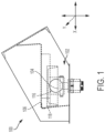
- Figures 1 , 2 , and 3 each schematically illustrate a first landing connection system 102 of a stair system 100.
- the first landing connection system 102 is disposed between a stair or staircase 106 and a landing 108.
- the landing 108 is an upper landing, while in other embodiments the landing 108 is a lower landing.
- a first landing connection system 102 can be operatively connected with an upper landing and a lower landing.
- the first landing connection system 102 includes a single-point connection device 104.
- the single point connection device 104 can include any of, by way of example only, a shaft configuration, a pin-type configuration, a nut-and-bolt configuration, a ball-and-socket configuration, a pin-type configuration, a ball-joint-rod-end configuration, a swivel joint configuration, a configuration in which one or more structural shapes fit together, or any other suitable configuration which provides for a single point connection.
- the single-point connection device 104 Upon connection with a stair or staircase 106, the single-point connection device 104 allows for rotational movement.
- the rotational movement includes movement in an X-direction and in a Y-direction.
- movement in the X-direction is movement in the transverse direction or side-to-side movement.
- movement in the Y-direction is movement in the longitudinal direction or back-and-forth movement.
- the single-point connection device 104 can include a coupler 116 and a cross channel 118.
- the cross channel 118 is disposed adjacent the single-point connection device 104.
- the coupler 116 and the cross channel 118 can operatively connect the first landing connection system 102 with the landing 108 and/or staircase 106.
- the cross channel 118 is U-shaped, however, any suitable shape can be utilized.
- the coupler 116 is a part of the single-point connection device 104 and receives the mating end of the single-point connection device 104.
- a positive connection is made via a pin configured to secure a ball into an acceptor. The pin, ball, and acceptor accommodate rotation and push the X and Y movements to the opposing connection.
- the first landing connection system 102 includes a base plate 110 for connection with the landing 108, as shown in Figures 2 and 3 , for example. Connection with the landing 108 can be made via any suitable connections means, for example, a bolted means. In some embodiments, one or more extenders 112 extend in an outward direction from the baseplate 110. As further shown in Figures 2 and 3 , by way crossbar 114 extends between the one or more extenders 112. The crossbar 114 includes a midpoint C. The single-point connection device 104 is centrally located proximate midpoint C within the first landing connection system 102.
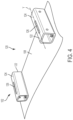
- Figures 4 , 5 , and 6 each schematically illustrate a second landing connection system 120 of the stair system 100.
- the second landing connection system includes at least one secondary movement connection device 122.
- the secondary movement connection device 122 includes a first face 124 with a slot 126 therethrough.
- the secondary movement connection device 122 is configured to be operatively connected with a stair or staircase 106 via any suitable connection, for example, a bolted connection.
- the secondary movement connection device 122 is configured for longitudinal movement in at least one direction, for example, in at least one of the X-direction and the Y-direction.
- movement in the X-direction is movement in the transverse direction, or side-to-side movement
- movement in the Y-direction is movement in the longitudinal direction, or back-and-forth movement.
- the staircase upon connection of the staircase 106 with the secondary movement connection device 122, the staircase is moveable in the longitudinal direction upon application of a force thereon.
- the at least one secondary movement connection device 122 includes a slotted connector, a track system connector, a guide rail connector, a wheeled connector, a roller connector, a slide connector, or a plate connector.
- Figure 7A schematically illustrates the stair system 100.
- the first landing connection system 102 shown in phantom, operatively connects an upper landing 202 with a staircase 206.
- the second landing connection system 120 shown in phantom in Figure 7B , operatively connects a lower landing 204 with the staircase 206.
- the first landing connection system 102 can operatively connect the lower landing 204 with the staircase 206
- the second landing connection 120 can operatively connect the upper landing 202 with the staircase 206.
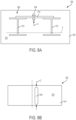
- Figures 8A and 8B each schematically illustrate features of a stair system 300.
- the stair system 300 includes a first landing connection system 302.
- the first landing connection system 302 is disposed between a stair or staircase and a landing.
- the landing is an upper landing, while in other embodiments the landing is a lower landing.
- a first landing connection system 302 can be operatively connected with an upper landing and a lower landing.
- the first landing connection system 302 can be operatively connected with a single landing whether it be an upper landing or a lower landing.
- the first landing connection system 302 includes a single-point connection device 304.
- the single point connection device 304 can include any of, by way of example only, a shaft configuration, a pin-type configuration, a nut-and-bolt configuration, a ball-and-socket configuration, a pin-type configuration, a ball-joint-rod-end configuration, a swivel joint configuration, a configuration in which one or more structural shapes fit together, or any other suitable configuration which provides for a single point connection.
- the single-point connection device 304 Upon connection with a stair or staircase, the single-point connection device 304 allows for rotational movement.
- the rotational movement includes movement in an X-direction and in a Y-direction. In some embodiments, movement in the X-direction is movement in the transverse direction, or side-to-side movement, while movement in the Y-direction is movement in the longitudinal direction, or back-and-forth movement.
- the first landing connection system 302 can include a coupler or a cross channel, as described further herein for embodiments shown in Figure 1 .
- the cross channel is disposed adjacent the single-point connection device 304.
- the coupler and the cross channel can operatively connect the first landing connection system 302 with the landing and/or staircase.
- the cross channel is U-shaped, however, any suitable shape can be utilized.
- the first landing connection system 302 includes a base plate 310 for connection with the landing. Connection with the landing can be made via any suitable connections means, for example, a bolted means.
- one or more extenders 312 extend in an outward direction from the baseplate 310. As shown in Figure 8A , by way of example only, the one or more extenders 312 are I-beams.
- the first landing connection system 302 includes a secondary movement connection system 308.
- the secondary movement connection system 308 includes a crossbar 314.
- the crossbar 314 extends between the one or more extenders 312.
- the crossbar 314 is coupled with the one or more extenders 312, for example, via a bolted connection, a welded connection, or any other suitable connection means.
- the crossbar can be a face, plate, beam, rail, or any other suitable device.
- the crossbar 314 includes a midpoint C.
- the single-point connection device 304 is centrally located proximate midpoint C within the first landing connection system 302.
- the secondary movement connection device 308 also includes a first face 318 of the crossbar 314.
- the first face 318 includes a slot 316 therein.
- the slot 316 can extend through the first face 318 or through the crossbar 314.
- the slot 316 can extend in the longitudinal director, in the lateral direction, or in an approximately diagonal direction.
- the single-point connection device is at least partially disposed through the slot to operatively connect the secondary movement connection device 308 with the single-point connection device 304, such that the single point connection device 304 is configured to move in the direction of the slot 316.
- the staircase upon connection of a staircase with a landing via the stair system of Figures 8A and 8B , the staircase is moveable in a rotational direction-in a combination of an X-direction and a Y-direction-as well as in a longitudinal direction-in at least one of the X-direction and the Y-direction.
- movement in the X-direction is movement in the transverse direction, or side-to-side movement
- movement in the Y-direction is movement in the longitudinal direction, or back-and-forth movement.
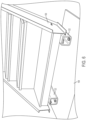
- Figure 9 schematically illustrates a moveable stair system 330.
- the moveable stair system includes a staircase 332 having one or more stairs 334.
- the first landing connection system 302 as discussed with reference to Figures 8A and 8B , supra, is disposed at a first end 306 of the staircase 332, wherein the first end 306 is opposite a second end 338.
- the first landing connection system 302 is operatively connected with a first landing 336 via any suitable connection means.
- the first landing connection system 302 includes the single-point connection device 304 and the secondary movement connection device 308.
- the staircase 332 is operatively connected with the first single-point connection device 308.
- the first landing connection system 302 includes a landing plate.
- the landing plate is operatively disposed to cover a gap between the staircase 332 and the first landing 336.
- a second end 338 of the staircase 332 can rest on the landing or floor 340, or in other embodiments, the second end 338 of the staircase 332 can be operatively connected with the landing or floor 340 via any suitable connection means.
- Exemplary benefits of stair systems in accordance with the disclosed subject matter include that the stair system allows for rotational movement to absorb landing displacement reducing damage to the stair system, thus allowing for safe egress.
- the disclosed connection means for connecting a staircase with a landing allows for the staircase to rotate, thus accommodating interstory drift in response to an event causing the structure to shake or move (i.e., earthquake, high winds, explosions, etc.).
- the present disclosure allows stairs the freedom to move to reduce force transfers to unsupported areas of a building, to maintain the structural integrity of the stairs during and after an event to allow for safe egress of occupants and safe ingress of emergency services to later allow for reoccupation of the building.
- the stair systems disclosed are easily disposed at the top or bottom of a flight of stairs, thus allowing all movement to be located at one point (e.g., an intermediate landing) as opposed to requiring each axis of movement to be located at opposite ends of the flight.
- one end of the flight of stairs can remain fixed or free and yet still provide the benefits of rotational movement.
- testing has been performed and results indicate that, during movement events, stairs tend to naturally move in a rotational direction. As such, the rotational movement permitted by the systems of the present disclosure reduces the risk of damage not only to the stairs or building, but also to adjacent architecture and structural components.
- the stair systems and methods disclosed allow for stair movement between building levels, platforms, landings, or the like while maintaining the structural integrity of the stair system for safe egress passage.
- the systems and methods disclosed further allow for independent movement of the surrounding building walls, landings, floor slabs, and/or any other portion of the surrounding building structure to the stair system.
- the embodiments of the present disclosure are suitable for use in both new constructions as well as in existing constructions for retrofit applications to allow for movement between levels, landings, or within stairwell structures.
- the present invention can reduce stair damage during building movement whether it is from wind, thermal, or seismic activity, and/or any other type of suitable force or experience, as the present invention allows for rotational movement, longitudinal movement, directional movement, or a combination thereof.
Landscapes
- Engineering & Computer Science (AREA)
- Architecture (AREA)
- Civil Engineering (AREA)
- Structural Engineering (AREA)
- Environmental & Geological Engineering (AREA)
- Business, Economics & Management (AREA)
- Emergency Management (AREA)
- Physics & Mathematics (AREA)
- Electromagnetism (AREA)
- Steps, Ramps, And Handrails (AREA)
Claims (15)
- Vorrichtung, die zur Verwendung in einem Treppensystem (300) geeignet ist, umfassend:
ein erstes Treppenabsatz-Verbindungssystem (302), umfassend:zwei oder mehrere Verlängerungen;eine Einzelpunkt-Verbindungsvorrichtung (304), die so konfiguriert ist, dass sie eine Drehbewegung ermöglicht, wobei die Drehbewegung eine Bewegung in einer Kombination aus einer X-Richtung und einer Y-Richtung ist; undeine sekundäre Bewegungsverbindungsvorrichtung (308), die mit der Einzelpunkt-Verbindungsvorrichtung (304) funktionsfähig verbunden ist und für eine Längsbewegung in mindestens einer der X-Richtung und der Y-Richtung konfiguriert ist,wobei die sekundäre Bewegungsverbindungsvorrichtung (308) eine Querstange (314) umfasst, die sich zwischen den zwei oder mehreren Verlängerungen (312) erstreckt, undwobei die Einzelpunkt-Verbindungsvorrichtung in der Nähe eines Mittelpunkts der Querstange angeordnet ist. - Vorrichtung nach Anspruch 1, wobei die Einzelpunkt-Verbindungsvorrichtung (304) mindestens eine der folgenden Konfigurationen aufweist: eine Wellenkonfiguration, eine Stiftkonfiguration, eine Mutter-und-Bolzen-Konfiguration, eine Kugelgelenkkonfiguration, eine Kupplungskonfiguration, eine Kugelgelenk-Stangenende-Konfiguration, eine Drehgelenkkonfiguration oder eine Konfiguration, in der eine oder mehrere strukturelle Formen zusammenpassen.
- Vorrichtung nach Anspruch 2, wobei die Querstange der sekundären Bewegungsverbindungsvorrichtung (308) eine erste Fläche (318) mit einem Schlitz (316) darin umfasst, und
wobei die Einzelpunkt-Verbindungsvorrichtung (304) zumindest teilweise durch den Schlitz (316) angeordnet ist, um die sekundäre Bewegungsverbindungsvorrichtung (308) funktionsfähig mit der Einzelpunkt-Verbindungsvorrichtung (304) zu verbinden. - Vorrichtung nach Anspruch 3, wobei die Einzelpunkt-Verbindungsvorrichtung (304) zentral innerhalb der ersten Fläche (318) angeordnet ist.
- Vorrichtung nach Anspruch 2, wobei die Einzelpunkt-Verbindungsvorrichtung (304) ferner einen Kuppler (116) und einen Querkanal (118) umfasst, wobei der Kuppler (116) und der Querkanal (118) so konfiguriert sind, dass sie das erste Treppenabsatz-Verbindungssystem (302) funktionsfähig mit einem ersten Treppenabsatz (336) oder einem Treppenlauf (332) des Treppensystems (300) verbinden.
- Vorrichtung nach Anspruch 1, ferner umfassend eine Treppenabsatzplatte, die funktionsfähig mit dem ersten Treppenabsatz-Verbindungssystem (302) verbunden ist und so konfiguriert ist, dass sie einen Spalt zwischen einem Treppenlauf (332) und einem ersten Treppenabsatz (336) abdeckt.
- Vorrichtung nach Anspruch 1 und ein erster Treppenabsatz, wobei das erste Treppenabsatz-Verbindungssystem (302) ferner funktionsfähig mit dem ersten Treppenabsatz (336) verbunden ist.
- Vorrichtung nach Anspruch 1, ferner umfassend ein zweites Treppenabsatz-Verbindungssystem (120).
- Bewegliches Treppensystem (100), umfassend:einen Treppenlauf (206) mit einer oder mehreren Treppen;eine Vorrichtung zur Verwendung in einem Treppensystem nach Anspruch 1, die an einem ersten Ende des Treppenlaufs (206) angeordnet ist; undein zweites Treppenabsatz-Verbindungssystem (120), das an einem zweiten Ende des Treppenlaufs (206) angeordnet ist, wobei das zweite Treppenabsatz-Verbindungssystem (120) eine sekundäre Bewegungsverbindungsvorrichtung (122) umfasst.
- Bewegliches Treppensystem (100) nach Anspruch 9, wobei die Einzelpunkt-Verbindungsvorrichtung (104) zentral innerhalb des ersten Treppenabsatz-Verbindungssystems (102) angeordnet ist.
- Bewegliches Treppensystem (100) nach Anspruch 9, wobei die Einzelpunkt-Verbindungsvorrichtung (104) mindestens eine der folgenden Konfigurationen aufweist: eine Schaftkonfiguration, eine Stiftkonfiguration, eine Mutter-und-Bolzen-Konfiguration, eine Kugelgelenkkonfiguration, eine Kupplungskonfiguration, eine Kugelgelenk-Stangenende-Konfiguration, eine Drehgelenkkonfiguration oder eine Konfiguration, in der eine oder mehrere strukturelle Formen zusammenpassen.
- Bewegliches Treppensystem (100) nach Anspruch 11, wobei die Einzelpunkt-Verbindungsvorrichtung (104) ferner einen Kuppler (116) und einen Querkanal (118) umfasst, wobei der Kuppler (116) und der Querkanal (118) so konfiguriert sind, dass sie die Einzelpunkt-Verbindungsvorrichtung (104) mit dem Treppenlauf (206) verbinden.
- Bewegliches Treppensystem (100) nach Anspruch 9, wobei die sekundäre Bewegungsverbindungsvorrichtung (122) einen geschlitzten Verbinder, einen Schienensystemverbinder, einen Führungsschienenverbinder, einen Radverbinder, einen Rollenverbinder, einen Gleitverbinder oder einen Plattenverbinder umfasst.
- Bewegliches Treppensystem (100) nach Anspruch 9, ein erster Treppenabsatz (202) und ein zweiter Treppenabsatz (204), wobei das erste Treppenabsatz-Verbindungssystem (102) ferner funktionsfähig mit dem ersten Treppenabsatz (202) verbunden ist und wobei das zweite Treppenabsatz-Verbindungssystem (120) ferner funktionsfähig mit dem zweiten Treppenabsatz (204) verbunden ist.
- Bewegliches Treppensystem (100) nach Anspruch 9, ferner umfassend eine Treppenabsatzplatte, die funktionsfähig mit dem ersten Treppenabsatz-Verbindungssystem verbunden ist und so konfiguriert ist, dass sie einen Spalt zwischen dem Treppenlauf und einem ersten Treppenabsatz abdeckt.
Applications Claiming Priority (2)
| Application Number | Priority Date | Filing Date | Title |
|---|---|---|---|
| US201862691058P | 2018-06-28 | 2018-06-28 | |
| PCT/US2019/037023 WO2020005560A1 (en) | 2018-06-28 | 2019-06-13 | Rotational connections for stairs |
Publications (3)
| Publication Number | Publication Date |
|---|---|
| EP3814581A1 EP3814581A1 (de) | 2021-05-05 |
| EP3814581A4 EP3814581A4 (de) | 2022-06-15 |
| EP3814581B1 true EP3814581B1 (de) | 2025-05-21 |
Family
ID=68987548
Family Applications (1)
| Application Number | Title | Priority Date | Filing Date |
|---|---|---|---|
| EP19826208.1A Active EP3814581B1 (de) | 2018-06-28 | 2019-06-13 | Drehverbindungen für treppen |
Country Status (6)
| Country | Link |
|---|---|
| US (1) | US11332923B2 (de) |
| EP (1) | EP3814581B1 (de) |
| CA (1) | CA3104870A1 (de) |
| ES (1) | ES3031133T3 (de) |
| MX (1) | MX2021000118A (de) |
| WO (1) | WO2020005560A1 (de) |
Families Citing this family (1)
| Publication number | Priority date | Publication date | Assignee | Title |
|---|---|---|---|---|
| EP4219858B1 (de) * | 2017-05-15 | 2025-12-17 | EMEH, Inc. | Bewegliches anpassungssystem für treppen |
Citations (1)
| Publication number | Priority date | Publication date | Assignee | Title |
|---|---|---|---|---|
| US4766708A (en) * | 1985-12-27 | 1988-08-30 | Peter Sing | Shock and vibration resistant structures |
Family Cites Families (35)
| Publication number | Priority date | Publication date | Assignee | Title |
|---|---|---|---|---|
| US2220155A (en) * | 1938-08-08 | 1940-11-05 | Jachim Frank | Folding stairway |
| US3299590A (en) * | 1964-06-01 | 1967-01-24 | Carter Lavoy | Prefabricated, adjustable stairway, ramp or bridge |
| US4039050A (en) * | 1969-05-13 | 1977-08-02 | Monsanto Company | Damping system |
| US3691712A (en) * | 1969-05-13 | 1972-09-19 | Monsanto Co | Damping system |
| US3626438A (en) * | 1969-12-15 | 1971-12-07 | Ozark Metal Products Inc | Adjustable stairs |
| US3693754A (en) * | 1971-03-16 | 1972-09-26 | Le Roy O Butler | Portable folding steps and landing for a mobile home and the like |
| US3946833A (en) * | 1973-12-13 | 1976-03-30 | Riehlmann Joseph F | Collapsible ladder suitable for use as fire escape |
| US3997026A (en) * | 1973-12-13 | 1976-12-14 | Riehlmann Joseph F | Collapsible ladder assembly suitable for use as fire escape |
| US3912298A (en) * | 1975-01-10 | 1975-10-14 | William D Humphrey | Foldable steps for mobile home |
| US4347638A (en) * | 1980-03-10 | 1982-09-07 | Weaver Murland L | Retractable porch and stair apparatus for trailers |
| US4642953A (en) * | 1986-02-10 | 1987-02-17 | Degood David A | Moveable stair apparatus |
| US4768617A (en) * | 1987-07-16 | 1988-09-06 | Wenger Corporation | Adjustable stairway having retractable wheel carriage |
| IT1222227B (it) * | 1988-04-01 | 1990-09-05 | Georgel Valentin Stanescu | Scala per l'imbarco e lo sbarco di passeggeri da imbarcazioni,con mezzi attuatori per il posizionamento ed il ritiro |
| US4959935A (en) * | 1989-09-25 | 1990-10-02 | Stob H Richard | Adjustable stairway |
| US5189854A (en) * | 1992-09-14 | 1993-03-02 | The United States Of America As Represented By The Secretary Of The Army | Adjustable height stairway |
| US6003270A (en) * | 1998-04-16 | 1999-12-21 | Macintyre; James R. | Variable riser seating system |
| US6868944B2 (en) * | 1998-05-21 | 2005-03-22 | Ez Stairs, Inc. | Adjustable stair stringer and railing |
| US6324795B1 (en) * | 1999-11-24 | 2001-12-04 | Ever-Level Foundation Systems, Inc. | Seismic isolation system between floor and foundation comprising a ball and socket joint and elastic or elastomeric element |
| US6527081B1 (en) * | 2001-05-30 | 2003-03-04 | Aluminum Ladder Company, | Embankment stairway |
| US6923140B1 (en) * | 2004-03-03 | 2005-08-02 | Aluminum Ladder Company | Boat access stairway |
| TW200809061A (en) | 2006-06-20 | 2008-02-16 | John Clement Preston | Stairway for use on building sites |
| US7967110B2 (en) * | 2006-07-27 | 2011-06-28 | Werner Co. | Tubular access ladder and method |
| US20080190049A1 (en) * | 2007-02-08 | 2008-08-14 | David Muti | Portable construction staircase |
| US7976746B2 (en) | 2007-03-26 | 2011-07-12 | Conservano Guy A | Method installing a modular concrete stair system |
| US20090300994A1 (en) | 2008-06-06 | 2009-12-10 | Atkins Iii Livingston Elwood | Removable stairway for an elevated platform and method |
| US8771544B2 (en) * | 2010-05-10 | 2014-07-08 | Larry James Hopper | Stair tower module |
| US8640826B1 (en) * | 2011-12-16 | 2014-02-04 | Richard R. Beilstein | Trailer rub rail portable ladder |
| US9290947B2 (en) * | 2012-07-31 | 2016-03-22 | Diamond Stairs Inc. | Stair systems and wall assemblies comprising same |
| ITTV20120171A1 (it) * | 2012-09-05 | 2014-03-06 | Daniele Pivetta | Modulo per realizzazione di scala modulare autoportante con struttura in acciaio |
| US9758981B2 (en) * | 2014-10-14 | 2017-09-12 | Emeh, Inc. | Stair expansion joint system with freedom of movement between landings |
| US9869084B2 (en) | 2014-10-14 | 2018-01-16 | Emeh, Inc. | Stair expansion joint system with freedom of movement between landings |
| ES2879866T3 (es) * | 2015-08-11 | 2021-11-23 | Zev Bianchi | Escalera retráctil |
| US10640983B2 (en) * | 2016-03-23 | 2020-05-05 | Safe Rack Llc | Platform system |
| EP4219858B1 (de) * | 2017-05-15 | 2025-12-17 | EMEH, Inc. | Bewegliches anpassungssystem für treppen |
| US10745919B1 (en) * | 2019-07-26 | 2020-08-18 | Big Time Investment, Llc | Method and apparatus for installing a staircase assembly into a building |
-
2019
- 2019-06-13 EP EP19826208.1A patent/EP3814581B1/de active Active
- 2019-06-13 ES ES19826208T patent/ES3031133T3/es active Active
- 2019-06-13 MX MX2021000118A patent/MX2021000118A/es unknown
- 2019-06-13 WO PCT/US2019/037023 patent/WO2020005560A1/en not_active Ceased
- 2019-06-13 US US17/255,983 patent/US11332923B2/en active Active
- 2019-06-13 CA CA3104870A patent/CA3104870A1/en active Pending
Patent Citations (1)
| Publication number | Priority date | Publication date | Assignee | Title |
|---|---|---|---|---|
| US4766708A (en) * | 1985-12-27 | 1988-08-30 | Peter Sing | Shock and vibration resistant structures |
Also Published As
| Publication number | Publication date |
|---|---|
| CA3104870A1 (en) | 2020-01-02 |
| US11332923B2 (en) | 2022-05-17 |
| EP3814581A1 (de) | 2021-05-05 |
| MX2021000118A (es) | 2021-03-09 |
| US20210115658A1 (en) | 2021-04-22 |
| WO2020005560A1 (en) | 2020-01-02 |
| NZ771746A (en) | 2024-10-25 |
| ES3031133T3 (en) | 2025-07-04 |
| EP3814581A4 (de) | 2022-06-15 |
Similar Documents
| Publication | Publication Date | Title |
|---|---|---|
| AU2023203238B2 (en) | Moveable stair systems and methods | |
| US6637580B1 (en) | Telescoping escalator seismic restraint | |
| KR101772362B1 (ko) | 대심도 지하철 정거장 구조 | |
| RU2178376C2 (ru) | Передвижная платформа | |
| US11332923B2 (en) | Rotational connections for stairs | |
| US11702855B1 (en) | Anti-seismic braced scissor stairs and frame stairs system | |
| US20020179368A1 (en) | Post-tensioned fall protection system | |
| US20090056243A1 (en) | Method and apparatus for retrofitting existing escalator systems | |
| JP2011017129A (ja) | 水平2次元方向に可動の自在手摺り構造 | |
| NZ771746B2 (en) | Rotational connections for stairs | |
| RU2499742C2 (ru) | Защитное устройство грузового самолета | |
| JP6692769B2 (ja) | 乗客コンベア及び乗客コンベアの設置方法 | |
| JP7464566B2 (ja) | 構造物 | |
| CN220058973U (zh) | 一种电梯井防护体系 | |
| US11898341B2 (en) | Building core and kit for assembly | |
| CN218149353U (zh) | 一种隔震楼梯结构 | |
| CN220318360U (zh) | 一种双肢爬模平台 | |
| CN221742097U (zh) | 钢结构高空作业用生命线系统 | |
| WO2011141945A1 (ja) | 乗客コンベア | |
| CN109057391A (zh) | 一种用于预防钢框架结构连续倒塌的局部加固结构 | |
| CN120717319A (zh) | 具有多重保护施工人员安全功能的上下竖井配套装置 | |
| JP3757046B2 (ja) | 乗客コンベア | |
| RU2307064C2 (ru) | Устройство для монтажа груза с помощью летательного аппарата | |
| CN119754497A (zh) | 快速组装的装配式建筑及其楼梯结构 | |
| CN112012054A (zh) | 一种悬挂式单轨轨道梁安装操作平台及其组装方法 |
Legal Events
| Date | Code | Title | Description |
|---|---|---|---|
| STAA | Information on the status of an ep patent application or granted ep patent |
Free format text: STATUS: THE INTERNATIONAL PUBLICATION HAS BEEN MADE |
|
| PUAI | Public reference made under article 153(3) epc to a published international application that has entered the european phase |
Free format text: ORIGINAL CODE: 0009012 |
|
| STAA | Information on the status of an ep patent application or granted ep patent |
Free format text: STATUS: REQUEST FOR EXAMINATION WAS MADE |
|
| 17P | Request for examination filed |
Effective date: 20210106 |
|
| AK | Designated contracting states |
Kind code of ref document: A1 Designated state(s): AL AT BE BG CH CY CZ DE DK EE ES FI FR GB GR HR HU IE IS IT LI LT LU LV MC MK MT NL NO PL PT RO RS SE SI SK SM TR |
|
| RIN1 | Information on inventor provided before grant (corrected) |
Inventor name: OSTOJIC, DARKO Inventor name: SMITH, KEVIN W. Inventor name: BELVIN, ROBERT J. Inventor name: PEACHY, ANTHONY J. |
|
| DAV | Request for validation of the european patent (deleted) | ||
| DAX | Request for extension of the european patent (deleted) | ||
| A4 | Supplementary search report drawn up and despatched |
Effective date: 20220513 |
|
| RIC1 | Information provided on ipc code assigned before grant |
Ipc: E04H 9/02 20060101ALI20220509BHEP Ipc: E04F 11/04 20060101ALI20220509BHEP Ipc: E04F 11/022 20060101ALI20220509BHEP Ipc: E04F 11/00 20060101ALI20220509BHEP Ipc: E04B 1/98 20060101ALI20220509BHEP Ipc: E04B 1/36 20060101AFI20220509BHEP |
|
| STAA | Information on the status of an ep patent application or granted ep patent |
Free format text: STATUS: EXAMINATION IS IN PROGRESS |
|
| 17Q | First examination report despatched |
Effective date: 20240326 |
|
| GRAP | Despatch of communication of intention to grant a patent |
Free format text: ORIGINAL CODE: EPIDOSNIGR1 |
|
| STAA | Information on the status of an ep patent application or granted ep patent |
Free format text: STATUS: GRANT OF PATENT IS INTENDED |
|
| INTG | Intention to grant announced |
Effective date: 20240927 |
|
| GRAJ | Information related to disapproval of communication of intention to grant by the applicant or resumption of examination proceedings by the epo deleted |
Free format text: ORIGINAL CODE: EPIDOSDIGR1 |
|
| STAA | Information on the status of an ep patent application or granted ep patent |
Free format text: STATUS: EXAMINATION IS IN PROGRESS |
|
| GRAP | Despatch of communication of intention to grant a patent |
Free format text: ORIGINAL CODE: EPIDOSNIGR1 |
|
| STAA | Information on the status of an ep patent application or granted ep patent |
Free format text: STATUS: GRANT OF PATENT IS INTENDED |
|
| INTC | Intention to grant announced (deleted) | ||
| INTG | Intention to grant announced |
Effective date: 20250107 |
|
| GRAS | Grant fee paid |
Free format text: ORIGINAL CODE: EPIDOSNIGR3 |
|
| GRAA | (expected) grant |
Free format text: ORIGINAL CODE: 0009210 |
|
| STAA | Information on the status of an ep patent application or granted ep patent |
Free format text: STATUS: THE PATENT HAS BEEN GRANTED |
|
| AK | Designated contracting states |
Kind code of ref document: B1 Designated state(s): AL AT BE BG CH CY CZ DE DK EE ES FI FR GB GR HR HU IE IS IT LI LT LU LV MC MK MT NL NO PL PT RO RS SE SI SK SM TR |
|
| REG | Reference to a national code |
Ref country code: GB Ref legal event code: FG4D |
|
| REG | Reference to a national code |
Ref country code: CH Ref legal event code: EP |
|
| REG | Reference to a national code |
Ref country code: DE Ref legal event code: R096 Ref document number: 602019070310 Country of ref document: DE |
|
| REG | Reference to a national code |
Ref country code: IE Ref legal event code: FG4D |
|
| REG | Reference to a national code |
Ref country code: ES Ref legal event code: FG2A Ref document number: 3031133 Country of ref document: ES Kind code of ref document: T3 Effective date: 20250704 |
|
| PGFP | Annual fee paid to national office [announced via postgrant information from national office to epo] |
Ref country code: DE Payment date: 20250627 Year of fee payment: 7 |
|
| PGFP | Annual fee paid to national office [announced via postgrant information from national office to epo] |
Ref country code: GB Payment date: 20250627 Year of fee payment: 7 |
|
| PGFP | Annual fee paid to national office [announced via postgrant information from national office to epo] |
Ref country code: FR Payment date: 20250625 Year of fee payment: 7 |
|
| REG | Reference to a national code |
Ref country code: NL Ref legal event code: MP Effective date: 20250521 |
|
| PG25 | Lapsed in a contracting state [announced via postgrant information from national office to epo] |
Ref country code: PT Free format text: LAPSE BECAUSE OF FAILURE TO SUBMIT A TRANSLATION OF THE DESCRIPTION OR TO PAY THE FEE WITHIN THE PRESCRIBED TIME-LIMIT Effective date: 20250922 Ref country code: FI Free format text: LAPSE BECAUSE OF FAILURE TO SUBMIT A TRANSLATION OF THE DESCRIPTION OR TO PAY THE FEE WITHIN THE PRESCRIBED TIME-LIMIT Effective date: 20250521 |
|
| PGFP | Annual fee paid to national office [announced via postgrant information from national office to epo] |
Ref country code: ES Payment date: 20250701 Year of fee payment: 7 |
|
| REG | Reference to a national code |
Ref country code: LT Ref legal event code: MG9D |
|
| PG25 | Lapsed in a contracting state [announced via postgrant information from national office to epo] |
Ref country code: NO Free format text: LAPSE BECAUSE OF FAILURE TO SUBMIT A TRANSLATION OF THE DESCRIPTION OR TO PAY THE FEE WITHIN THE PRESCRIBED TIME-LIMIT Effective date: 20250821 Ref country code: GR Free format text: LAPSE BECAUSE OF FAILURE TO SUBMIT A TRANSLATION OF THE DESCRIPTION OR TO PAY THE FEE WITHIN THE PRESCRIBED TIME-LIMIT Effective date: 20250822 |
|
| PG25 | Lapsed in a contracting state [announced via postgrant information from national office to epo] |
Ref country code: PL Free format text: LAPSE BECAUSE OF FAILURE TO SUBMIT A TRANSLATION OF THE DESCRIPTION OR TO PAY THE FEE WITHIN THE PRESCRIBED TIME-LIMIT Effective date: 20250521 Ref country code: NL Free format text: LAPSE BECAUSE OF FAILURE TO SUBMIT A TRANSLATION OF THE DESCRIPTION OR TO PAY THE FEE WITHIN THE PRESCRIBED TIME-LIMIT Effective date: 20250521 |
|
| PGFP | Annual fee paid to national office [announced via postgrant information from national office to epo] |
Ref country code: IT Payment date: 20250619 Year of fee payment: 7 |
|
| PG25 | Lapsed in a contracting state [announced via postgrant information from national office to epo] |
Ref country code: BG Free format text: LAPSE BECAUSE OF FAILURE TO SUBMIT A TRANSLATION OF THE DESCRIPTION OR TO PAY THE FEE WITHIN THE PRESCRIBED TIME-LIMIT Effective date: 20250521 |
|
| PG25 | Lapsed in a contracting state [announced via postgrant information from national office to epo] |
Ref country code: HR Free format text: LAPSE BECAUSE OF FAILURE TO SUBMIT A TRANSLATION OF THE DESCRIPTION OR TO PAY THE FEE WITHIN THE PRESCRIBED TIME-LIMIT Effective date: 20250521 |
|
| PG25 | Lapsed in a contracting state [announced via postgrant information from national office to epo] |
Ref country code: RS Free format text: LAPSE BECAUSE OF FAILURE TO SUBMIT A TRANSLATION OF THE DESCRIPTION OR TO PAY THE FEE WITHIN THE PRESCRIBED TIME-LIMIT Effective date: 20250821 |
|
| PG25 | Lapsed in a contracting state [announced via postgrant information from national office to epo] |
Ref country code: IS Free format text: LAPSE BECAUSE OF FAILURE TO SUBMIT A TRANSLATION OF THE DESCRIPTION OR TO PAY THE FEE WITHIN THE PRESCRIBED TIME-LIMIT Effective date: 20250921 |
|
| PG25 | Lapsed in a contracting state [announced via postgrant information from national office to epo] |
Ref country code: LV Free format text: LAPSE BECAUSE OF FAILURE TO SUBMIT A TRANSLATION OF THE DESCRIPTION OR TO PAY THE FEE WITHIN THE PRESCRIBED TIME-LIMIT Effective date: 20250521 |
|
| REG | Reference to a national code |
Ref country code: AT Ref legal event code: MK05 Ref document number: 1796865 Country of ref document: AT Kind code of ref document: T Effective date: 20250521 |
|
| PG25 | Lapsed in a contracting state [announced via postgrant information from national office to epo] |
Ref country code: SM Free format text: LAPSE BECAUSE OF FAILURE TO SUBMIT A TRANSLATION OF THE DESCRIPTION OR TO PAY THE FEE WITHIN THE PRESCRIBED TIME-LIMIT Effective date: 20250521 Ref country code: DK Free format text: LAPSE BECAUSE OF FAILURE TO SUBMIT A TRANSLATION OF THE DESCRIPTION OR TO PAY THE FEE WITHIN THE PRESCRIBED TIME-LIMIT Effective date: 20250521 Ref country code: AT Free format text: LAPSE BECAUSE OF FAILURE TO SUBMIT A TRANSLATION OF THE DESCRIPTION OR TO PAY THE FEE WITHIN THE PRESCRIBED TIME-LIMIT Effective date: 20250521 |
|
| PG25 | Lapsed in a contracting state [announced via postgrant information from national office to epo] |
Ref country code: CZ Free format text: LAPSE BECAUSE OF FAILURE TO SUBMIT A TRANSLATION OF THE DESCRIPTION OR TO PAY THE FEE WITHIN THE PRESCRIBED TIME-LIMIT Effective date: 20250521 |
|
| PG25 | Lapsed in a contracting state [announced via postgrant information from national office to epo] |
Ref country code: EE Free format text: LAPSE BECAUSE OF FAILURE TO SUBMIT A TRANSLATION OF THE DESCRIPTION OR TO PAY THE FEE WITHIN THE PRESCRIBED TIME-LIMIT Effective date: 20250521 |
|
| PG25 | Lapsed in a contracting state [announced via postgrant information from national office to epo] |
Ref country code: SK Free format text: LAPSE BECAUSE OF FAILURE TO SUBMIT A TRANSLATION OF THE DESCRIPTION OR TO PAY THE FEE WITHIN THE PRESCRIBED TIME-LIMIT Effective date: 20250521 Ref country code: RO Free format text: LAPSE BECAUSE OF FAILURE TO SUBMIT A TRANSLATION OF THE DESCRIPTION OR TO PAY THE FEE WITHIN THE PRESCRIBED TIME-LIMIT Effective date: 20250521 |
|
| REG | Reference to a national code |
Ref country code: CH Ref legal event code: H13 Free format text: ST27 STATUS EVENT CODE: U-0-0-H10-H13 (AS PROVIDED BY THE NATIONAL OFFICE) Effective date: 20260127 |
|
| PG25 | Lapsed in a contracting state [announced via postgrant information from national office to epo] |
Ref country code: LU Free format text: LAPSE BECAUSE OF NON-PAYMENT OF DUE FEES Effective date: 20250613 |
|
| PG25 | Lapsed in a contracting state [announced via postgrant information from national office to epo] |
Ref country code: MC Free format text: LAPSE BECAUSE OF FAILURE TO SUBMIT A TRANSLATION OF THE DESCRIPTION OR TO PAY THE FEE WITHIN THE PRESCRIBED TIME-LIMIT Effective date: 20250521 |
|
| REG | Reference to a national code |
Ref country code: DE Ref legal event code: R097 Ref document number: 602019070310 Country of ref document: DE |
|
| REG | Reference to a national code |
Ref country code: BE Ref legal event code: MM Effective date: 20250630 |
|
| PLBE | No opposition filed within time limit |
Free format text: ORIGINAL CODE: 0009261 |
|
| STAA | Information on the status of an ep patent application or granted ep patent |
Free format text: STATUS: NO OPPOSITION FILED WITHIN TIME LIMIT |
|
| REG | Reference to a national code |
Ref country code: CH Ref legal event code: L10 Free format text: ST27 STATUS EVENT CODE: U-0-0-L10-L00 (AS PROVIDED BY THE NATIONAL OFFICE) Effective date: 20260402 |
|
| PG25 | Lapsed in a contracting state [announced via postgrant information from national office to epo] |
Ref country code: IE Free format text: LAPSE BECAUSE OF NON-PAYMENT OF DUE FEES Effective date: 20250613 |
|
| PG25 | Lapsed in a contracting state [announced via postgrant information from national office to epo] |
Ref country code: BE Free format text: LAPSE BECAUSE OF NON-PAYMENT OF DUE FEES Effective date: 20250630 |
|
| PG25 | Lapsed in a contracting state [announced via postgrant information from national office to epo] |
Ref country code: CH Free format text: LAPSE BECAUSE OF NON-PAYMENT OF DUE FEES Effective date: 20250630 |
|
| 26N | No opposition filed |
Effective date: 20260224 |