EP3814207B1 - Grätschsitzfahrzeug mit staufach - Google Patents
Grätschsitzfahrzeug mit staufach Download PDFInfo
- Publication number
- EP3814207B1 EP3814207B1 EP19724789.3A EP19724789A EP3814207B1 EP 3814207 B1 EP3814207 B1 EP 3814207B1 EP 19724789 A EP19724789 A EP 19724789A EP 3814207 B1 EP3814207 B1 EP 3814207B1
- Authority
- EP
- European Patent Office
- Prior art keywords
- closed position
- supporting unit
- tilting vehicle
- covering
- stowage compartment
- Prior art date
- Legal status (The legal status is an assumption and is not a legal conclusion. Google has not performed a legal analysis and makes no representation as to the accuracy of the status listed.)
- Active
Links
Images


Classifications
-
- B—PERFORMING OPERATIONS; TRANSPORTING
- B62—LAND VEHICLES FOR TRAVELLING OTHERWISE THAN ON RAILS
- B62K—CYCLES; CYCLE FRAMES; CYCLE STEERING DEVICES; RIDER-OPERATED TERMINAL CONTROLS SPECIALLY ADAPTED FOR CYCLES; CYCLE AXLE SUSPENSIONS; CYCLE SIDECARS, FORECARS, OR THE LIKE
- B62K19/00—Cycle frames
- B62K19/46—Luggage carriers forming part of frame
-
- B—PERFORMING OPERATIONS; TRANSPORTING
- B62—LAND VEHICLES FOR TRAVELLING OTHERWISE THAN ON RAILS
- B62J—CYCLE SADDLES OR SEATS; AUXILIARY DEVICES OR ACCESSORIES SPECIALLY ADAPTED TO CYCLES AND NOT OTHERWISE PROVIDED FOR, e.g. ARTICLE CARRIERS OR CYCLE PROTECTORS
- B62J9/00—Containers specially adapted for cycles, e.g. panniers or saddle bags
- B62J9/10—Containers specially adapted for cycles, e.g. panniers or saddle bags integrated with the cycle
- B62J9/14—Containers specially adapted for cycles, e.g. panniers or saddle bags integrated with the cycle under the saddle
Definitions
- the invention relates to a tilting vehicle with at least one storage compartment which can be arranged in or on a vehicle housing and which comprises at least one cavity and at least one opening making the cavity accessible from the outside, with at least one covering means which, in a closed position, at least covers the opening of the storage compartment almost entirely and which, in a release position, releases the opening to the outside and with at least one support unit, through which the transfer of the covering means from the closed position to the release position and/or vice versa can be at least supported by a support force, with the storage compartment with respect to the longitudinal direction of the Tilting vehicle is accessible from the side and wherein the support unit comprises at least one damper element and at least one spring element.
- Tilting vehicles are known, for example, in the form of motorcycles or scooters.
- known tilting vehicles can have a storage compartment which, when the tilting vehicle is in operation, is closed to the outside by a seat designed as a cover element.
- the bench seat In order to gain access to the storage compartment, the bench seat is rotated about an axis of rotation, for example, and a motorcycle helmet, item of clothing or the like is placed in the storage compartment.
- tilting vehicles are known in which the cover element and the bench seat comprise two components that are separate or separable from one another.
- EP 1 557 348 A2 shows the preamble of claim 1.
- a tilting vehicle with a storage compartment that is accessible from the side in the longitudinal direction is known from EP 3 088 287 A1 .
- An object of an exemplary embodiment of the invention is to propose a tilting vehicle in which the transfer of the covering means from the closed position to the release position and/or vice versa is facilitated.
- At least one frame means which can be fixed to the opening of the storage compartment and which forms a receptacle for the support unit and/or the guide means, the frame means comprising a sealing element which seals the cavity of the storage compartment at least in the closed position of the cover element surrounds at least almost the entire circumference.
- the support unit and/or the guide means can be fixed to the vehicle housing or to the storage compartment.
- the support unit and/or guide means can be fixed to different storage compartments in a simple manner by the frame means. In such a case, the support unit and/or guide means can easily be retrofitted to storage compartments.
- the sealing element can prevent dirt or moisture from penetrating inside the storage compartment, at least in the closed position of the cover element.
- the sealing element is formed around the full circumference between the cover element and the storage compartment.
- a support unit makes it easier to operate the storage compartment, in particular the covering means, manually with one hand.
- a tilting vehicle is understood to mean bicycles, motorcycles or motorbike-like motor vehicles such as motor scooters, in particular two-, three- or four-wheeled motor scooters, scooters, tilting trikes, quads or the like.
- the storage compartment is accessible from the side with respect to the longitudinal direction of the vehicle.
- the covering means can have any desired design, for example flap-like, sliding-door-like or roller-blind-like.
- the support unit comprises a damping element
- the movement from the closed position to the release position is counteracted with a support force, in particular when the covering means is transferred from the closed position to the release position.
- This slows down the transfer of the covering means from the closed position to the release position.
- the guide elements arranged between the cover element and the storage compartment such as rails, joints or hinges, can be relieved and their wear is reduced as a result.
- the covering means can be pretensioned, for example, in the closed position or in the release position. If the covering means is pretensioned in the closed position, the covering means is automatically transferred from the release position to the closing position when manual actuation of the covering means has ended. Furthermore, when the covering means is biased into the release position by the spring element, the covering means is automatically transferred from the closed position to the release position as soon as the covering means is released from the closed position.
- the support unit includes at least one drive.
- the damper element, the spring element and/or the drive can be implemented mechanically, electromagnetically, hydraulically and/or pneumatically.
- the at least one damper element of the support unit comprises an opening damper, rotary damper, linear damper and/or a gas spring
- the at least one spring element of the support unit comprises at least one spring and/or spiral spring and/or if the at least one drive of the support unit comprises at least one toothed rack, a looped rope, a spindle drive, a shape memory element and/or a direct drive.
- the support unit can be provided simply and inexpensively.
- the covering means can be automatically transferred from the closed position to the release position, or from the release position to the closed position, without manual intervention.
- the cover means can be fixed to the storage compartment and by which the transfer of the cover means from the closed position to the release position and/or vice versa can be guided.
- the guiding means can be of any desired design, as long as it fulfills the technical function of guiding the covering means from the closed position to the release position and/or vice versa.
- the transfer of the covering means from the closed position to the release position and/or vice versa comprises a rotary movement, with the guide means comprising a joint, a hinge, a multi-joint hinge and/or bracket hinge and/or if the transferring of the covering means of the Closing position in the release position and / or vice versa includes a linear movement, wherein the guide means is rail-like or rod-shaped.
- a guide means can be implemented in a simple manner.
- the support unit can be arranged at any desired location as long as it supports the transfer of the covering means from the closed position to the release position and/or vice versa.
- the support unit can be arranged between the storage compartment and the guide means or can be an element of the guide means.
- the covering means is held in the closed position by the damping element, the spring element and/or by the drive.
- the support unit comprises at least one holding means that fixes the cover element in the closed position on the storage compartment and/or that triggers the damper element, the spring element and/or the drive when the cover element is released from the closed position.
- the holding means comprises a rotary latch lock.
- figure 1 shows a tilting vehicle provided overall with the reference number 2 in a schematic, side perspective view.
- the tilting vehicle 2 comprises a storage compartment 4 which is located in a vehicle housing 6 (in figure 1 only indicated schematically) can be arranged.
- the storage compartment 4 comprises a cavity 8 and at least one opening 10 making the cavity 8 accessible from the outside Release position releases the opening 10 to the outside.
- figure 1 shows the covering means 12 in a release position.
- the tilting vehicle 2 includes a support unit 14, by means of which the transfer of the covering means 12 from the closed position to the release position and/or vice versa can be at least supported by a support force.
- figure 2 shows a first exemplary embodiment of the tilting vehicle 2, in which the support unit 14 is formed by a spring element 16. Through the spring element 16 can be used to preload the covering means 12 into the closed position.
- the covering means 12 is connected to the storage compartment 4 via a guide means 20 designed as a joint 18 .
- a guide means 20 designed as a joint 18 .
- figure 3 shows a second exemplary embodiment of the tilting vehicle 2, in which the support unit 14 is formed by a damping element 22.
- This in figure 3 visible damper element 22 comprises a rotary damper.
- FIG figure 4 shows a holding means 24 of the tilting vehicle 2, which is used in FIG figure 4 shown embodiment is designed as a rotary latch lock.
- the covering means 12 can be fixed in the closed position by the holding means 24 .
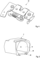
- figure 5 12 shows a third exemplary embodiment of the tilting vehicle 2, in which the tilting vehicle 2 comprises a frame means 26.
- the frame means 26 can be fixed to the opening 10 of the storage compartment 4 and forms a receptacle 28 for the support unit 14. In the case of FIG figure 5 shown embodiment, the frame means 26 is clipped into the storage compartment 4.
Landscapes
- Engineering & Computer Science (AREA)
- Mechanical Engineering (AREA)
- Vehicle Step Arrangements And Article Storage (AREA)
- Closing And Opening Devices For Wings, And Checks For Wings (AREA)
Description
- Die Erfindung betrifft ein Neigefahrzeug mit mindestens einem Staufach, das in oder an einem Fahrzeuggehäuse anordenbar ist und das mindestens einen Hohlraum und mindestens eine, den Hohlraum von außen zugänglich machende Öffnung umfasst, mit mindestens einem Abdeckmittel, das in einer Verschlussstellung die Öffnung des Staufachs zumindest nahezu in Gänze überfängt und das in einer Freigabestellung die Öffnung nach außen freigibt und mit mindestens eine Unterstützungseinheit, durch die das Überführen des Abdeckmittels von der Verschlussstellung in die Freigabestellung und/oder umgekehrt durch eine Unterstützungskraft zumindest unterstützbar ist, wobei das Staufach bezüglich der Längsrichtung des Neigefahrzeugs seitlich zugänglich ist und wobei die Unterstützungseinheit mindestens ein Dämpferelement und mindestens ein Federelement umfasst.
- Neigefahrzeuge sind beispielsweise in Form von Motorrädern oder Rollern bekannt. Um Gegenstände zu bevorraten, können bekannte Neigefahrzeuge ein Staufach umfassen, das beim Betrieb des Neigefahrzeugs durch eine als Abdeckelement ausgebildete Sitzbank nach außen geschlossen ist. Um Zugriff auf das Staufach zu erhalten, wird die Sitzbank beispielsweise um eine Drehachse gedreht und ein Motorradhelm, Bekleidungsstück oder Dergleichen in dem Staufach abgelegt.
- Darüber hinaus sind Neigefahrzeuge bekannt, bei denen das Abdeckelement und die Sitzbank zwei voneinander separate oder separierbare Bauteile umfassen.
- Ein Neigefahrzeug, bei dem das Staufach bezüglich der Längsrichtung von hinten aus zugänglich ist, ist bekannt aus
EP 1 557 348 A2 . DokumentEP 1 557 348 A2 zeigt den Oberbegriff des Anspruchs 1. - Ein Neigefahrzeug mit einem bezüglich der Längsrichtung seitlich zugänglichen Staufach ist bekannt aus
EP 3 088 287 A1 . - Bei den bekannten Neigefahrzeugen kann sich ein manuelles Überführen des Abdeckmittels von der Verschlussstellung in die Freigabestellung und/oder umgekehrt als umständlich erweisen, insbesondere wenn der Bediener hierfür nur eine Hand frei hat.
- Eine Aufgabe eines Ausführungsbeispiels der Erfindung ist, ein Neigefahrzeug vorzuschlagen, bei dem das Überführen des Abdeckmittels von der Verschlussstellung in die Freigabestellung und/oder umgekehrt, erleichtert ist.
- Diese Aufgabe wird bei einem eingangs genannten Neigefahrzeug gelöst durch mindestens ein Rahmenmittel, das an der Öffnung des Staufachs festlegbar ist und das eine Aufnahme für die Unterstützungseinheit und/oder das Führungsmittel bildet, wobei das Rahmenmittel ein Dichtelement umfasst, das den Hohlraum des Staufachs zumindest in der Verschlussstellung des Abdeckelements zumindest nahezu vollumfänglich umgibt.
- Die Unterstützungseinheit und/oder das Führungsmittel können am Fahrzeuggehäuse oder am Staufach festgelegt sein. Unterstützungseinheit und/oder Führungsmittel lassen sich durch das Rahmenmittel auf einfache Art und Weise an unterschiedlichen Staufächern festlegen. Solchenfalls können Unterstützungseinheit und/oder Führungsmittel auf einfache Weise an Staufächern nachgerüstet werden.
- Durch das Dichtelement Solchenfalls kann ein Eindringen von Verschmutzung oder Feuchtigkeit innerhalb des Staufaches, zumindest in der Verschlussstellung des Abdeckelements vorgebeugt werden. Hierbei erweist es sich insbesondere als vorteilhaft, wenn das Dichtelement voll umfänglich zwischen Abdeckelement und Staufach ausgebildet ist.
- Durch das Vorsehen einer Unterstützungseinheit ist ein einhändiges manuelles Bedienen des Staufachs, insbesondere des Abdeckmittels, erleichtert.
- Unter einem Neigefahrzeug werden Fahrräder, Motorräder oder Motorradähnliche Kraftfahrzeuge, wie Motorroller, insbesondere zwei-, drei- oder vierrädrige Motorroller, Scooter, neigbare Trikes, Quads oder Dergleichen verstanden.
- Das Staufach ist bezüglich der Längsrichtung des Fahrzeugs seitlich zugänglich. Das Abdeckmittel kann grundsätzlich beliebig ausgebildet sein, beispielsweise klappenartig, schiebetürartig oder rolloartig.
- Dadurch, dass die Unterstützungseinheit ein Dämpferelement umfasst, wird insbesondere bei einem Überführen des Abdeckmittels von der Verschlussstellung in die Freigabestellung mit einer Unterstützungskraft der Bewegung von der Verschlussstellung in die Freigabestellung entgegengewirkt. Hierdurch ist ein Überführen des Abdeckmittels von der Verschlussstellung in die Freigabestellung verlangsamt. Dieses erweist sich insbesondere insofern als vorteilhaft, dass zwischen dem Abdeckelement und dem Staufach angeordnete Führungselemente, wie Schienen, Gelenke oder Scharniere entlastbar sind und hierdurch deren Verschleiß reduziert ist.
- Dadurch, dass die Unterstützungseinheit ein Federelement umfasst, kann das Abdeckmittel beispielsweise in die Verschlussstellung oder in die Freigabestellung vorgespannt sein. Wenn das Abdeckmittel in die Verschlussstellung vorgespannt ist, wird das Abdeckmittel automatisch von der Freigabestellung in die Verschlussstellung überführt, wenn ein manuelles Betätigen des Abdeckmittels beendet ist. Ferner, wenn das Abdeckmittel durch das Federelement in die Freigabestellung vorgespannt ist, wird das Abdeckmittel automatisch von der Verschlussstellung in die Freigabestellung überführt, sobald das Abdeckmittel aus der Verschlussstellung gelöst ist.
- Es erweist sich als vorteilhaft, wenn die Unterstützungseinheit mindestens einen Antrieb umfasst.
- Das Dämpferelement, das Federelement und/oder der Antrieb können mechanisch, elektromagnetisch, hydraulisch und/oder pneumatisch realisiert sein.
- Bei Ausführungsformen der Unterstützungseinheit hat es sich als vorteilhaft herausgestellt, wenn das mindestens eine Dämpferelement der Unterstützungseinheit einen Öffnungsdämpfer, Rotationsdämpfer, Lineardämpfer und/oder eine Gasfeder umfasst, wenn das mindestens eine Federelement der Unterstützungseinheit mindestens eine Feder und/oder Spiralfeder umfasst und/oder wenn der mindestens eine Antrieb der Unterstützungseinheit mindestens eine Zahnstange, eine Seilumschlingung, einen Spindelantrieb, ein Formgedächtniselement und/oder einen Direktantrieb umfasst.
- Solchenfalls ist die Unterstützungseinheit einfach und kostengünstig bereitstellbar.
- Wenn die Unterstützungseinheit einen Antrieb umfasst, kann das Abdeckmittel ohne manuelles Zutun automatisch von der Verschlussstellung in die Freigabestellung, bzw. von der Freigabestellung in die Verschlussstellung automatisch überführt werden.
- Darüber hinaus erweist es sich als vorteilhaft, wenn das Abdeckmittel an dem Staufach festlegbar ist und durch das das Überführen des Abdeckmittels von der Verschlussstellung in die Freigabestellung und/oder umgekehrt führbar ist.
- Das Führungsmittel kann grundsätzlich beliebig ausgebildet sein, sofern es der technischen Funktion nachkommt, das Abdeckmittel von der Verschlussstellung in die Freigabestellung und/oder umgekehrt zu führen. Solchenfalls erweist es sich als vorteilhaft, wenn das Überführen des Abdeckmittels von der Verschlussstellung in die Freigabestellung und/oder umgekehrt eine Drehbewegung umfasst, wobei das Führungsmittel ein Gelenk, ein Scharnier, ein Mehrgelenkscharnier und/oder Bügelscharnier umfasst und/oder wenn das Überführen des Abdeckmittels von der Verschlussstellung in die Freigabestellung und/oder umgekehrt eine lineare Bewegung umfasst, wobei das Führungsmittel schienenartig oder stangenförmig ausgebildet ist.
- Hierdurch ist auf einfache Weise ein Führungsmittel realisierbar.
- Die Unterstützungseinheit kann an einer beliebigen Stelle angeordnet sein, sofern sie das Überführen des Abdeckmittels von der Verschlussstellung in die Freigabestellung und/oder umgekehrt unterstützt. Die Unterstützungseinheit kann zwischen Staufach und Führungsmittel angeordnet sein oder Element des Führungsmittels sein.
- Es ist denkbar, dass das Abdeckmittel in der Verschlussstellung durch das Dämpfelement, das Federelement und/oder durch den Antrieb gehalten ist. Bei einer Ausführungsform ist vorgesehen, dass die Unterstützungseinheit mindestens ein Haltemittel umfasst, das das Abdeckelement in der Verschlussstellung am Staufach festlegt und/oder das bei Lösen des Abdeckelements aus der Verschlussstellung das Dämpferelement, das Federelement und/oder den Antrieb auslöst.
- Solchenfalls ist ein unbeabsichtigtes Überführen des Abdeckelements aus der Verschlussstellung in die Freigabestellung vorgebeugt.
- Bei einer Weiterbildung letztgenannter Ausführungsform erweist es sich als vorteilhaft, wenn das Haltemittel ein Drehfallschloss umfasst.
- Weitere Merkmale, Einzelheiten und Vorteile der Erfindung ergeben sich aus den beigefügten Patentansprüchen, aus der zeichnerischen Darstellung und nachfolgenden Beschreibung bevorzugter Ausführungsformen des Neigefahrzeugs.
- In der Zeichnung zeigt:
- Figur 1
- Eine schematische perspektivische Seitenansicht auf ein erfindungsgemäßes Neigefahrzeug;
- Figur 2
- Eine perspektivische Detailansicht auf ein erstes Ausführungsbeispiel des Neigefahrzeugs mit einer als Federelement ausgebildeten Unterstützungseinheit;
- Figur 3
- Eine perspektivische Detailansicht auf ein zweites Ausführungsbeispiel des Neigefahrzeugs mit einer als Dämpferelement ausgebildeten Unterstützungseinheit;
- Figur 4
- Eine perspektivische Detailansicht eines Haltemittels des Neigefahrzeugs;
- Figur 5
- Eine perspektivische Seitenansicht auf ein drittes Ausführungsbeispiel des Neigefahrzeugs mit einem Rahmenmittel.
-
Figur 1 zeigt ein insgesamt mit dem Bezugszeichen 2 versehenes Neigefahrzeug in einer schematischen, seitlichen perspektivischen Ansicht. - Das Neigefahrzeug 2 umfasst ein Staufach 4, das in einem Fahrzeuggehäuse 6 (in
Figur 1 nur schematisch angedeutet) anordenbar ist. Das Staufach 4 umfasst einen Hohlraum 8 und mindestens eine, den Hohlraum 8 von außen zugänglich machende Öffnung 10. Darüber hinaus umfasst das Neigefahrzeug 2 ein Abdeckmittel 12, das in einer Verschlussstellung die Öffnung 10 des Staufachs 4 zumindest nahezu in Gänze überfängt und das in einer Freigabestellung die Öffnung 10 nach außen freigibt.Figur 1 zeigt das Abdeckmittel 12 in einer Freigabestellung. - Darüber hinaus umfasst das Neigefahrzeug 2 eine Unterstützungseinheit 14, durch die das Überführen des Abdeckmittels 12 von der Verschlussstellung in die Freigabestellung und/oder umgekehrt durch eine Unterstützungskraft zumindest unterstützbar ist.
-
Figur 2 zeigt ein erstes Ausführungsbeispiel des Neigefahrzeugs 2, bei der die Unterstützungseinheit 14 durch ein Federelement 16 gebildet ist. Durch das Federelement 16 ist das Abdeckmittel 12 in die Verschlussstellung vorspannbar. - Darüber hinaus ist in
Figur 2 ersichtlich, dass das Abdeckmittel 12 über ein als Gelenk 18 ausgebildetes Führungsmittel 20 mit dem Staufach 4 verbunden ist. Hierdurch ist das Überführen des Abdeckmittels 12 von der Verschlussstellung in die Freigabestellung und umgekehrt auf einfache Weise führbar. -
Figur 3 zeigt ein zweites Ausführungsbeispiel des Neigefahrzeugs 2, bei dem die Unterstützungseinheit 14 durch ein Dämpferelement 22 ausgebildet ist. - Das in
Figur 3 ersichtliche Dämpferelement 22 umfasst einen Rotationsdämpfer. -
Figur 4 zeigt ein Haltemittel 24 des Neigefahrzeugs 2, das bei dem inFigur 4 gezeigten Ausführungsbeispiel als Drehfallschloss ausgebildet ist. Durch das Haltemittel 24 ist das Abdeckmittel 12 in der Verschlussstellung festlegbar. -
Figur 5 zeigt ein drittes Ausführungsbeispiel des Neigefahrzeugs 2, bei der das Neigefahrzeug 2 ein Rahmenmittel 26 umfasst. Das Rahmenmittel 26 ist an der Öffnung 10 des Staufachs 4 festlegbar und bildet eine Aufnahme 28 für die Unterstützungseinheit 14. Bei dem inFigur 5 gezeigten Ausführungsbeispiel ist das Rahmenmittel 26 in das Staufach 4 angeclipst. -
- 2
- Neigefahrzeug
- 4
- Stauchfach
- 6
- Fahrzeuggehäuse
- 8
- Hohlraum
- 10
- Öffnung
- 12
- Abdeckmittel
- 14
- Unterstützungseinheit
- 16
- Federelement
- 18
- Gelenk
- 20
- Führungsmittel
- 22
- Dämpferelement
- 24
- Haltemittel
- 26
- Rahmenmittel
- 28
- Aufnahme
Claims (8)
- Neigefahrzeug (2) mit mindestens einem Staufach (4), das in oder an einem Fahrzeuggehäuse (6) anordenbar ist und das mindestens einen Hohlraum (8) und mindestens eine, den Hohlraum (8) von außen zugänglich machende Öffnung (10) umfasst, mit mindestens einem Abdeckmittel (12), das in einer Verschlussstellung die Öffnung (10) des Staufachs (4) zumindest nahezu in Gänze überfängt und das in einer Freigabestellung die Öffnung (10) nach außen freigibt, mit mindestens eine Unterstützungseinheit (14), durch die das Überführen des Abdeckmittels (12) von der Verschlussstellung in die Freigabestellung und/oder umgekehrt durch eine Unterstützungskraft zumindest unterstützbar ist, wobei die Unterstützungseinheit (14) mindestens ein Dämpferelement (22) und mindestens ein Federelement (16) umfasst, dadurch gekennzeichnet, dass das Staufach bezüglich der Längsrichtung des Neigefahrzeugs (2) seitlich zugänglich ist und gekennzeichnet durch mindestens ein Rahmenmittel (26), das an der Öffnung (10) des Staufachs (4) festlegbar ist und das eine Aufnahme (28) für die Unterstützungseinheit (14) und/oder das Führungsmittel (20) bildet, wobei das Rahmenmittel (26) ein Dichtelement umfasst, das den Hohlraum (8) des Staufachs (4) zumindest in der Verschlussstellung des Abdeckmittels (12) zumindest nahezu vollumfänglich umgibt.
- Neigefahrzeug (2) nach Anspruch 1, dadurch gekennzeichnet, dass die Unterstützungseinheit (14) mindestens einen Antrieb umfasst.
- Neigefahrzeug (2) nach Anspruch 1 oder 2, dadurch gekennzeichnet, dass das mindestens eine Dämpferelement (22) der Unterstützungseinheit (14) einen Öffnungsdämpfer, Rotationsdämpfer, Lineardämpfer und/oder eine Gasfeder umfasst, dass das mindestens eine Federelement (16) der Unterstützungseinheit (14) mindestens eine Feder und/oder Spiralfeder umfasst und/oder dass der mindestens eine Antrieb der Unterstützungseinheit (14) mindestens eine Zahnstange, eine Seilumschlingung, einen Spindelantrieb, ein Formgedächtniselement und/oder einen Direktantrieb umfasst.
- Neigefahrzeug (2) nach mindestens einem der vorhergehenden Ansprüche, gekennzeichnet durch mindestens ein Führungsmittel (20), durch das das Abdeckmittel (12) an dem Staufach (4) festlegbar ist und durch das das Überführen des Abdeckmittels (12) von der Verschlussstellung in die Freigabestellung und/oder umgekehrt führbar ist.
- Neigefahrzeug (2) nach Anspruch 4, dadurch gekennzeichnet, dass das Überführen des Abdeckmittels (12) von der Verschlussstellung in die Freigabestellung und/oder umgekehrt eine Drehbewegung umfasst, wobei das Führungsmittel (20) ein Gelenk (18), ein Scharnier, ein Mehrgelenkscharnier und/oder Bügelscharnier umfasst und/oder dass das Überführen des Abdeckmittels (12) von der Verschlussstellung in die Freigabestellung und/oder umgekehrt eine lineare Bewegung umfasst, wobei das Führungsmittel (20) schienenartig oder stangenförmig ausgebildet ist.
- Neigefahrzeug (2) nach einem der Ansprüche 4 oder 5, dadurch gekennzeichnet, dass die Unterstützungseinheit (14) zwischen Staufach (4) und Führungsmittel (20) angeordnet ist oder dass die Unterstützungseinheit (14) Element des Führungsmittels (20) ist.
- Neigefahrzeug (2) nach mindestens einem der vorhergehenden Ansprüche, dadurch gekennzeichnet, dass die Unterstützungseinheit (14) mindestens ein Haltemittel (24) umfasst, das das Abdeckelement in der Verschlussstellung am Staufach (4) festlegt und/oder das bei Lösen des Abdeckelements aus der Verschlussstellung das Dämpferelement (22), das Federelement (16) und/oder den Antrieb auslöst.
- Neigefahrzeug (2) nach Anspruch 7, dadurch gekennzeichnet, dass das Haltemittel (24) ein Drehfallschloss umfasst.
Applications Claiming Priority (2)
| Application Number | Priority Date | Filing Date | Title |
|---|---|---|---|
| DE102018210355.0A DE102018210355A1 (de) | 2018-06-26 | 2018-06-26 | Neigefahrzeug |
| PCT/EP2019/062330 WO2020001843A1 (de) | 2018-06-26 | 2019-05-14 | Grätschsitzfahrzeug mit staufach |
Publications (2)
| Publication Number | Publication Date |
|---|---|
| EP3814207A1 EP3814207A1 (de) | 2021-05-05 |
| EP3814207B1 true EP3814207B1 (de) | 2023-05-10 |
Family
ID=66589537
Family Applications (1)
| Application Number | Title | Priority Date | Filing Date |
|---|---|---|---|
| EP19724789.3A Active EP3814207B1 (de) | 2018-06-26 | 2019-05-14 | Grätschsitzfahrzeug mit staufach |
Country Status (3)
| Country | Link |
|---|---|
| EP (1) | EP3814207B1 (de) |
| DE (1) | DE102018210355A1 (de) |
| WO (1) | WO2020001843A1 (de) |
Families Citing this family (1)
| Publication number | Priority date | Publication date | Assignee | Title |
|---|---|---|---|---|
| IT202100002147A1 (it) * | 2021-02-02 | 2022-08-02 | Piaggio & C Spa | Contenitore portaoggetti per veicolo a sella cavalcabile |
Citations (1)
| Publication number | Priority date | Publication date | Assignee | Title |
|---|---|---|---|---|
| EP3088287A1 (de) * | 2015-04-28 | 2016-11-02 | Yamaha Hatsudoki Kabushiki Kaisha | Grätschsitzfahrzeug |
Family Cites Families (8)
| Publication number | Priority date | Publication date | Assignee | Title |
|---|---|---|---|---|
| EP0982225A1 (de) * | 1998-08-21 | 2000-03-01 | Lumberton International Inc. | Schutzvorrichtung für eine Flasche auf einem Fahrrad oder ähnliches Fahrzeug |
| ATE211094T1 (de) * | 2000-03-21 | 2002-01-15 | Gi Vi Srl | Motorradkoffer mit gesteuerter bewegung des schliessmechanismus |
| US6793110B2 (en) * | 2002-12-19 | 2004-09-21 | William R. Hamilton | Motorcycle saddlebag assembly |
| JP4434784B2 (ja) * | 2003-04-04 | 2010-03-17 | 本田技研工業株式会社 | 鞍乗り型車両の収納部構造 |
| US7219939B2 (en) * | 2004-01-20 | 2007-05-22 | Honda Motor Co., Ltd. | Lock release operator layout structure in vehicle |
| JP4673654B2 (ja) * | 2005-03-31 | 2011-04-20 | 本田技研工業株式会社 | 自動二輪車用サイドトランクのロック装置 |
| DE102013220335A1 (de) * | 2013-10-09 | 2015-04-09 | Bayerische Motoren Werke Aktiengesellschaft | Gepäckkoffer |
| US20150184429A1 (en) * | 2013-12-26 | 2015-07-02 | Chiao-Pen Juan | Linking-up lock device for automatically opening and closing one or more luggage boxes of a motorcycle |
-
2018
- 2018-06-26 DE DE102018210355.0A patent/DE102018210355A1/de active Pending
-
2019
- 2019-05-14 EP EP19724789.3A patent/EP3814207B1/de active Active
- 2019-05-14 WO PCT/EP2019/062330 patent/WO2020001843A1/de not_active Ceased
Patent Citations (1)
| Publication number | Priority date | Publication date | Assignee | Title |
|---|---|---|---|---|
| EP3088287A1 (de) * | 2015-04-28 | 2016-11-02 | Yamaha Hatsudoki Kabushiki Kaisha | Grätschsitzfahrzeug |
Also Published As
| Publication number | Publication date |
|---|---|
| EP3814207A1 (de) | 2021-05-05 |
| WO2020001843A1 (de) | 2020-01-02 |
| DE102018210355A1 (de) | 2020-01-02 |
Similar Documents
| Publication | Publication Date | Title |
|---|---|---|
| DE19946454C2 (de) | Eine Öffnungs- und Schließvorrichtung für einen Kofferraumdeckel eines Fahrzeugs | |
| DE69902067T2 (de) | Schwenk- und Schiebekofferraumdeckel für Cabriofahrzeug mit Faltverdeck | |
| DE19729900C1 (de) | Dämpfungseinrichtung | |
| DE102004048245A1 (de) | Motorrad | |
| DE102015012734A1 (de) | Rahmen für ein Fahrrad | |
| DE10228399A1 (de) | Staufach für ein Fahrzeug | |
| DE102017105790A1 (de) | Verriegelungsstruktur für einen öffenbaren Körper eines Kraftfahrzeugs und Verfahren zur Verriegelung eines öffenbaren Körpers für ein Kraftfahrzeug | |
| DE102004038221B4 (de) | Verdeck für ein Cabriolet-Fahrzeug | |
| EP3814207A1 (de) | Grätschsitzfahrzeug mit staufach | |
| EP1084883B2 (de) | Cabriolet-Fahrzeug | |
| DE19963668B4 (de) | Cabriolet-Fahrzeug | |
| DE102017100935B4 (de) | Verriegelungsmechanismus für einen Deckel eines Ablagefachs eines Kraftfahrzeugs | |
| DE10017712B4 (de) | Kraftfahrzeug mit einem bewegbaren Heckteil zum Verschließen einer Hecköffnung | |
| DE102011004198A1 (de) | Saddle bag and motorcycle having the same | |
| DE10120769A1 (de) | Schwenksitzanordnung für ein Fahrzeug mit einem Schwenkantrieb | |
| DE102013111924A1 (de) | Cabriolet-Fahrzeug mit Abdeckelement für Gestängedurchtrittsöffnung | |
| DE202004001804U1 (de) | Konsole, insbesondere Mittelkonsole für ein Kraftfahrzeug | |
| EP1609652B1 (de) | Verdeck für ein Cabriolet-Fahrzeug | |
| DE102004005865B3 (de) | Verdeck für ein Cabriolet-Fahrzeug | |
| DE10121888A1 (de) | Dachanordnung für ein Fahrzeug | |
| EP1084886A2 (de) | Cabriolet-Fahrzeug | |
| DE1143724B (de) | Vorrichtung zur formschluessigen Verriegelung einer seitlich verschwenkbaren Kraftwagen-lenksaeule in der Betriebsstellung | |
| DE102018209533A1 (de) | Neigefahrzeug | |
| EP1609651B1 (de) | Abdeckvorrichtung für eine in einem oberen, hinteren Seitenwandbereich eines Cabrioletfahrzeuges angeordnete Durchgangsöffnung | |
| DE102017112209B3 (de) | Trennvorrichtung für Stauraum eines Cabriolet-Fahrzeugs sowie Cabriolet-Fahrzeug mit derartiger Trennvorrichtung |
Legal Events
| Date | Code | Title | Description |
|---|---|---|---|
| STAA | Information on the status of an ep patent application or granted ep patent |
Free format text: STATUS: UNKNOWN |
|
| STAA | Information on the status of an ep patent application or granted ep patent |
Free format text: STATUS: THE INTERNATIONAL PUBLICATION HAS BEEN MADE |
|
| PUAI | Public reference made under article 153(3) epc to a published international application that has entered the european phase |
Free format text: ORIGINAL CODE: 0009012 |
|
| STAA | Information on the status of an ep patent application or granted ep patent |
Free format text: STATUS: REQUEST FOR EXAMINATION WAS MADE |
|
| 17P | Request for examination filed |
Effective date: 20201118 |
|
| AK | Designated contracting states |
Kind code of ref document: A1 Designated state(s): AL AT BE BG CH CY CZ DE DK EE ES FI FR GB GR HR HU IE IS IT LI LT LU LV MC MK MT NL NO PL PT RO RS SE SI SK SM TR |
|
| DAV | Request for validation of the european patent (deleted) | ||
| DAX | Request for extension of the european patent (deleted) | ||
| STAA | Information on the status of an ep patent application or granted ep patent |
Free format text: STATUS: EXAMINATION IS IN PROGRESS |
|
| 17Q | First examination report despatched |
Effective date: 20220302 |
|
| RIC1 | Information provided on ipc code assigned before grant |
Ipc: B62J 9/14 20200101ALI20221215BHEP Ipc: B62K 19/46 20060101ALI20221215BHEP Ipc: B62J 9/00 20200101AFI20221215BHEP |
|
| GRAP | Despatch of communication of intention to grant a patent |
Free format text: ORIGINAL CODE: EPIDOSNIGR1 |
|
| STAA | Information on the status of an ep patent application or granted ep patent |
Free format text: STATUS: GRANT OF PATENT IS INTENDED |
|
| INTG | Intention to grant announced |
Effective date: 20230124 |
|
| GRAS | Grant fee paid |
Free format text: ORIGINAL CODE: EPIDOSNIGR3 |
|
| GRAA | (expected) grant |
Free format text: ORIGINAL CODE: 0009210 |
|
| STAA | Information on the status of an ep patent application or granted ep patent |
Free format text: STATUS: THE PATENT HAS BEEN GRANTED |
|
| AK | Designated contracting states |
Kind code of ref document: B1 Designated state(s): AL AT BE BG CH CY CZ DE DK EE ES FI FR GB GR HR HU IE IS IT LI LT LU LV MC MK MT NL NO PL PT RO RS SE SI SK SM TR |
|
| REG | Reference to a national code |
Ref country code: GB Ref legal event code: FG4D Free format text: NOT ENGLISH |
|
| REG | Reference to a national code |
Ref country code: AT Ref legal event code: REF Ref document number: 1566444 Country of ref document: AT Kind code of ref document: T Effective date: 20230515 Ref country code: CH Ref legal event code: EP |
|
| REG | Reference to a national code |
Ref country code: DE Ref legal event code: R096 Ref document number: 502019007700 Country of ref document: DE |
|
| REG | Reference to a national code |
Ref country code: IE Ref legal event code: FG4D Free format text: LANGUAGE OF EP DOCUMENT: GERMAN |
|
| P01 | Opt-out of the competence of the unified patent court (upc) registered |
Effective date: 20230502 |
|
| REG | Reference to a national code |
Ref country code: LT Ref legal event code: MG9D |
|
| P02 | Opt-out of the competence of the unified patent court (upc) changed |
Effective date: 20230808 |
|
| REG | Reference to a national code |
Ref country code: NL Ref legal event code: MP Effective date: 20230510 |
|
| PG25 | Lapsed in a contracting state [announced via postgrant information from national office to epo] |
Ref country code: SE Free format text: LAPSE BECAUSE OF FAILURE TO SUBMIT A TRANSLATION OF THE DESCRIPTION OR TO PAY THE FEE WITHIN THE PRESCRIBED TIME-LIMIT Effective date: 20230510 Ref country code: PT Free format text: LAPSE BECAUSE OF FAILURE TO SUBMIT A TRANSLATION OF THE DESCRIPTION OR TO PAY THE FEE WITHIN THE PRESCRIBED TIME-LIMIT Effective date: 20230911 Ref country code: NO Free format text: LAPSE BECAUSE OF FAILURE TO SUBMIT A TRANSLATION OF THE DESCRIPTION OR TO PAY THE FEE WITHIN THE PRESCRIBED TIME-LIMIT Effective date: 20230810 Ref country code: NL Free format text: LAPSE BECAUSE OF FAILURE TO SUBMIT A TRANSLATION OF THE DESCRIPTION OR TO PAY THE FEE WITHIN THE PRESCRIBED TIME-LIMIT Effective date: 20230510 Ref country code: ES Free format text: LAPSE BECAUSE OF FAILURE TO SUBMIT A TRANSLATION OF THE DESCRIPTION OR TO PAY THE FEE WITHIN THE PRESCRIBED TIME-LIMIT Effective date: 20230510 |
|
| PG25 | Lapsed in a contracting state [announced via postgrant information from national office to epo] |
Ref country code: RS Free format text: LAPSE BECAUSE OF FAILURE TO SUBMIT A TRANSLATION OF THE DESCRIPTION OR TO PAY THE FEE WITHIN THE PRESCRIBED TIME-LIMIT Effective date: 20230510 Ref country code: PL Free format text: LAPSE BECAUSE OF FAILURE TO SUBMIT A TRANSLATION OF THE DESCRIPTION OR TO PAY THE FEE WITHIN THE PRESCRIBED TIME-LIMIT Effective date: 20230510 Ref country code: LV Free format text: LAPSE BECAUSE OF FAILURE TO SUBMIT A TRANSLATION OF THE DESCRIPTION OR TO PAY THE FEE WITHIN THE PRESCRIBED TIME-LIMIT Effective date: 20230510 Ref country code: LT Free format text: LAPSE BECAUSE OF FAILURE TO SUBMIT A TRANSLATION OF THE DESCRIPTION OR TO PAY THE FEE WITHIN THE PRESCRIBED TIME-LIMIT Effective date: 20230510 Ref country code: IS Free format text: LAPSE BECAUSE OF FAILURE TO SUBMIT A TRANSLATION OF THE DESCRIPTION OR TO PAY THE FEE WITHIN THE PRESCRIBED TIME-LIMIT Effective date: 20230910 Ref country code: HR Free format text: LAPSE BECAUSE OF FAILURE TO SUBMIT A TRANSLATION OF THE DESCRIPTION OR TO PAY THE FEE WITHIN THE PRESCRIBED TIME-LIMIT Effective date: 20230510 Ref country code: GR Free format text: LAPSE BECAUSE OF FAILURE TO SUBMIT A TRANSLATION OF THE DESCRIPTION OR TO PAY THE FEE WITHIN THE PRESCRIBED TIME-LIMIT Effective date: 20230811 |
|
| PG25 | Lapsed in a contracting state [announced via postgrant information from national office to epo] |
Ref country code: FI Free format text: LAPSE BECAUSE OF FAILURE TO SUBMIT A TRANSLATION OF THE DESCRIPTION OR TO PAY THE FEE WITHIN THE PRESCRIBED TIME-LIMIT Effective date: 20230510 |
|
| REG | Reference to a national code |
Ref country code: CH Ref legal event code: PL |
|
| PG25 | Lapsed in a contracting state [announced via postgrant information from national office to epo] |
Ref country code: SK Free format text: LAPSE BECAUSE OF FAILURE TO SUBMIT A TRANSLATION OF THE DESCRIPTION OR TO PAY THE FEE WITHIN THE PRESCRIBED TIME-LIMIT Effective date: 20230510 |
|
| REG | Reference to a national code |
Ref country code: BE Ref legal event code: MM Effective date: 20230531 |
|
| PG25 | Lapsed in a contracting state [announced via postgrant information from national office to epo] |
Ref country code: SM Free format text: LAPSE BECAUSE OF FAILURE TO SUBMIT A TRANSLATION OF THE DESCRIPTION OR TO PAY THE FEE WITHIN THE PRESCRIBED TIME-LIMIT Effective date: 20230510 Ref country code: SK Free format text: LAPSE BECAUSE OF FAILURE TO SUBMIT A TRANSLATION OF THE DESCRIPTION OR TO PAY THE FEE WITHIN THE PRESCRIBED TIME-LIMIT Effective date: 20230510 Ref country code: RO Free format text: LAPSE BECAUSE OF FAILURE TO SUBMIT A TRANSLATION OF THE DESCRIPTION OR TO PAY THE FEE WITHIN THE PRESCRIBED TIME-LIMIT Effective date: 20230510 Ref country code: LU Free format text: LAPSE BECAUSE OF NON-PAYMENT OF DUE FEES Effective date: 20230514 Ref country code: LI Free format text: LAPSE BECAUSE OF NON-PAYMENT OF DUE FEES Effective date: 20230531 Ref country code: EE Free format text: LAPSE BECAUSE OF FAILURE TO SUBMIT A TRANSLATION OF THE DESCRIPTION OR TO PAY THE FEE WITHIN THE PRESCRIBED TIME-LIMIT Effective date: 20230510 Ref country code: DK Free format text: LAPSE BECAUSE OF FAILURE TO SUBMIT A TRANSLATION OF THE DESCRIPTION OR TO PAY THE FEE WITHIN THE PRESCRIBED TIME-LIMIT Effective date: 20230510 Ref country code: CZ Free format text: LAPSE BECAUSE OF FAILURE TO SUBMIT A TRANSLATION OF THE DESCRIPTION OR TO PAY THE FEE WITHIN THE PRESCRIBED TIME-LIMIT Effective date: 20230510 Ref country code: CH Free format text: LAPSE BECAUSE OF NON-PAYMENT OF DUE FEES Effective date: 20230531 |
|
| REG | Reference to a national code |
Ref country code: DE Ref legal event code: R097 Ref document number: 502019007700 Country of ref document: DE |
|
| PG25 | Lapsed in a contracting state [announced via postgrant information from national office to epo] |
Ref country code: MC Free format text: LAPSE BECAUSE OF FAILURE TO SUBMIT A TRANSLATION OF THE DESCRIPTION OR TO PAY THE FEE WITHIN THE PRESCRIBED TIME-LIMIT Effective date: 20230510 |
|
| REG | Reference to a national code |
Ref country code: IE Ref legal event code: MM4A |
|
| PG25 | Lapsed in a contracting state [announced via postgrant information from national office to epo] |
Ref country code: MC Free format text: LAPSE BECAUSE OF FAILURE TO SUBMIT A TRANSLATION OF THE DESCRIPTION OR TO PAY THE FEE WITHIN THE PRESCRIBED TIME-LIMIT Effective date: 20230510 |
|
| PLBE | No opposition filed within time limit |
Free format text: ORIGINAL CODE: 0009261 |
|
| STAA | Information on the status of an ep patent application or granted ep patent |
Free format text: STATUS: NO OPPOSITION FILED WITHIN TIME LIMIT |
|
| PG25 | Lapsed in a contracting state [announced via postgrant information from national office to epo] |
Ref country code: IE Free format text: LAPSE BECAUSE OF NON-PAYMENT OF DUE FEES Effective date: 20230514 |
|
| 26N | No opposition filed |
Effective date: 20240213 |
|
| PG25 | Lapsed in a contracting state [announced via postgrant information from national office to epo] |
Ref country code: IE Free format text: LAPSE BECAUSE OF NON-PAYMENT OF DUE FEES Effective date: 20230514 |
|
| PG25 | Lapsed in a contracting state [announced via postgrant information from national office to epo] |
Ref country code: SI Free format text: LAPSE BECAUSE OF FAILURE TO SUBMIT A TRANSLATION OF THE DESCRIPTION OR TO PAY THE FEE WITHIN THE PRESCRIBED TIME-LIMIT Effective date: 20230510 |
|
| PG25 | Lapsed in a contracting state [announced via postgrant information from national office to epo] |
Ref country code: SI Free format text: LAPSE BECAUSE OF FAILURE TO SUBMIT A TRANSLATION OF THE DESCRIPTION OR TO PAY THE FEE WITHIN THE PRESCRIBED TIME-LIMIT Effective date: 20230510 Ref country code: BE Free format text: LAPSE BECAUSE OF NON-PAYMENT OF DUE FEES Effective date: 20230531 |
|
| PG25 | Lapsed in a contracting state [announced via postgrant information from national office to epo] |
Ref country code: BG Free format text: LAPSE BECAUSE OF FAILURE TO SUBMIT A TRANSLATION OF THE DESCRIPTION OR TO PAY THE FEE WITHIN THE PRESCRIBED TIME-LIMIT Effective date: 20230510 |
|
| PG25 | Lapsed in a contracting state [announced via postgrant information from national office to epo] |
Ref country code: BG Free format text: LAPSE BECAUSE OF FAILURE TO SUBMIT A TRANSLATION OF THE DESCRIPTION OR TO PAY THE FEE WITHIN THE PRESCRIBED TIME-LIMIT Effective date: 20230510 |
|
| PGFP | Annual fee paid to national office [announced via postgrant information from national office to epo] |
Ref country code: DE Payment date: 20250512 Year of fee payment: 7 |
|
| PGFP | Annual fee paid to national office [announced via postgrant information from national office to epo] |
Ref country code: GB Payment date: 20250522 Year of fee payment: 7 |
|
| PGFP | Annual fee paid to national office [announced via postgrant information from national office to epo] |
Ref country code: IT Payment date: 20250530 Year of fee payment: 7 |
|
| REG | Reference to a national code |
Ref country code: AT Ref legal event code: MM01 Ref document number: 1566444 Country of ref document: AT Kind code of ref document: T Effective date: 20240514 |
|
| PGFP | Annual fee paid to national office [announced via postgrant information from national office to epo] |
Ref country code: FR Payment date: 20250521 Year of fee payment: 7 |
|
| PG25 | Lapsed in a contracting state [announced via postgrant information from national office to epo] |
Ref country code: AT Free format text: LAPSE BECAUSE OF NON-PAYMENT OF DUE FEES Effective date: 20240514 |
|
| PG25 | Lapsed in a contracting state [announced via postgrant information from national office to epo] |
Ref country code: CY Free format text: LAPSE BECAUSE OF FAILURE TO SUBMIT A TRANSLATION OF THE DESCRIPTION OR TO PAY THE FEE WITHIN THE PRESCRIBED TIME-LIMIT; INVALID AB INITIO Effective date: 20190514 |
|
| PG25 | Lapsed in a contracting state [announced via postgrant information from national office to epo] |
Ref country code: HU Free format text: LAPSE BECAUSE OF FAILURE TO SUBMIT A TRANSLATION OF THE DESCRIPTION OR TO PAY THE FEE WITHIN THE PRESCRIBED TIME-LIMIT; INVALID AB INITIO Effective date: 20190514 |
|
| PG25 | Lapsed in a contracting state [announced via postgrant information from national office to epo] |
Ref country code: TR Free format text: LAPSE BECAUSE OF FAILURE TO SUBMIT A TRANSLATION OF THE DESCRIPTION OR TO PAY THE FEE WITHIN THE PRESCRIBED TIME-LIMIT Effective date: 20230510 |
|
| PGFP | Annual fee paid to national office [announced via postgrant information from national office to epo] |
Ref country code: AT Payment date: 20260410 Year of fee payment: 5 |