EP3812331B1 - Method for testing a capacity of a drive rescue battery of a transportation system, testing arrangement and computer program product - Google Patents
Method for testing a capacity of a drive rescue battery of a transportation system, testing arrangement and computer program product Download PDFInfo
- Publication number
- EP3812331B1 EP3812331B1 EP19204757.9A EP19204757A EP3812331B1 EP 3812331 B1 EP3812331 B1 EP 3812331B1 EP 19204757 A EP19204757 A EP 19204757A EP 3812331 B1 EP3812331 B1 EP 3812331B1
- Authority
- EP
- European Patent Office
- Prior art keywords
- phase
- lcl
- filter
- rectifier circuit
- inductor
- Prior art date
- Legal status (The legal status is an assumption and is not a legal conclusion. Google has not performed a legal analysis and makes no representation as to the accuracy of the status listed.)
- Active
Links
Images


Classifications
-
- G—PHYSICS
- G01—MEASURING; TESTING
- G01R—MEASURING ELECTRIC VARIABLES; MEASURING MAGNETIC VARIABLES
- G01R31/00—Arrangements for testing electric properties; Arrangements for locating electric faults; Arrangements for electrical testing characterised by what is being tested not provided for elsewhere
- G01R31/36—Arrangements for testing, measuring or monitoring the electrical condition of accumulators or electric batteries, e.g. capacity or state of charge [SoC]
- G01R31/385—Arrangements for measuring battery or accumulator variables
- G01R31/387—Determining ampere-hour charge capacity or SoC
- G01R31/388—Determining ampere-hour charge capacity or SoC involving voltage measurements
-
- B—PERFORMING OPERATIONS; TRANSPORTING
- B66—HOISTING; LIFTING; HAULING
- B66B—ELEVATORS; ESCALATORS OR MOVING WALKWAYS
- B66B5/00—Applications of checking, fault-correcting, or safety devices in elevators
- B66B5/0006—Monitoring devices or performance analysers
- B66B5/0037—Performance analysers
-
- B—PERFORMING OPERATIONS; TRANSPORTING
- B66—HOISTING; LIFTING; HAULING
- B66B—ELEVATORS; ESCALATORS OR MOVING WALKWAYS
- B66B5/00—Applications of checking, fault-correcting, or safety devices in elevators
- B66B5/02—Applications of checking, fault-correcting, or safety devices in elevators responsive to abnormal operating conditions
- B66B5/027—Applications of checking, fault-correcting, or safety devices in elevators responsive to abnormal operating conditions to permit passengers to leave an elevator car in case of failure, e.g. moving the car to a reference floor or unlocking the door
-
- G—PHYSICS
- G01—MEASURING; TESTING
- G01R—MEASURING ELECTRIC VARIABLES; MEASURING MAGNETIC VARIABLES
- G01R31/00—Arrangements for testing electric properties; Arrangements for locating electric faults; Arrangements for electrical testing characterised by what is being tested not provided for elsewhere
- G01R31/36—Arrangements for testing, measuring or monitoring the electrical condition of accumulators or electric batteries, e.g. capacity or state of charge [SoC]
- G01R31/3644—Constructional arrangements
- G01R31/3647—Constructional arrangements for determining the ability of a battery to perform a critical function, e.g. cranking
-
- G—PHYSICS
- G01—MEASURING; TESTING
- G01R—MEASURING ELECTRIC VARIABLES; MEASURING MAGNETIC VARIABLES
- G01R31/00—Arrangements for testing electric properties; Arrangements for locating electric faults; Arrangements for electrical testing characterised by what is being tested not provided for elsewhere
- G01R31/36—Arrangements for testing, measuring or monitoring the electrical condition of accumulators or electric batteries, e.g. capacity or state of charge [SoC]
- G01R31/367—Software therefor, e.g. for battery testing using modelling or look-up tables
-
- Y—GENERAL TAGGING OF NEW TECHNOLOGICAL DEVELOPMENTS; GENERAL TAGGING OF CROSS-SECTIONAL TECHNOLOGIES SPANNING OVER SEVERAL SECTIONS OF THE IPC; TECHNICAL SUBJECTS COVERED BY FORMER USPC CROSS-REFERENCE ART COLLECTIONS [XRACs] AND DIGESTS
- Y02—TECHNOLOGIES OR APPLICATIONS FOR MITIGATION OR ADAPTATION AGAINST CLIMATE CHANGE
- Y02B—CLIMATE CHANGE MITIGATION TECHNOLOGIES RELATED TO BUILDINGS, e.g. HOUSING, HOUSE APPLIANCES OR RELATED END-USER APPLICATIONS
- Y02B50/00—Energy efficient technologies in elevators, escalators and moving walkways, e.g. energy saving or recuperation technologies
Definitions
- the invention relates to method for testing a capacity of a drive rescue battery for driving an electric motor of a transportation system in a rescue operation mode, a software program, and a testing arrangement.
- a transportation system such as an elevator, an escalator, a moving walkway or the like my come to an unintended halt concerning a safety of passengers using the transportation system.
- An elevator may become stalled between floors in the elevator hoistway until the power supply returns to the nominal operating voltage range.
- passengers in the elevator may be trapped until a maintenance worker is able to release a brake for controlling cab movement upwardly or downwardly to allow the elevator to move to the closest floor.
- elevator systems employing automatic rescue operation have been introduced. These elevator systems include electrical energy storage devices, e.g.
- An integrated rescue feature of new generation drives for elevators thus enables battery discharging to drive internal loads such as moving the trapped elevator car up or down to the closest floor.
- US 2018/057309 A1 discloses a testing arrangement according to the preamble of claim 10.
- the method according to the invention for testing a capacity of a drive rescue battery for driving an electric motor of a transportation system in a rescue operation mode comprises the steps:
- the LCL filter (LCL stands for inductor L - capacitor C - inductor L) is used to reduce higher-order harmonics caused by the switching frequency of electronically switchable switching means of the rectifier circuit, e.g. in the form of insulated gate bipolar transistors (IGBTs).
- LCL filters in T-form are low pass filters especially designed to reduce harmonics of current absorbed by power converters, with a rectifier input stage such as the rectifier circuit of the frequency converter.
- LCL filters are made of a parallel-series combination of reactors or inductors and capacitors adapted to reduce the Total Harmonic Distortion of the current, abbreviated THD(I), of rectifiers.
- the LCL-filter may be disconnected from the AC mains downstream of an EMI-filter (EMI is the short form of electromagnetic i nterference) which is connected to the AC means.
- EMI is the short form of electromagnetic i nterference
- the rectifier circuit may be in the form of an Active Front End (AF ⁇ ). Rather than using diodes in the rectifier circuit to convert the incoming AC voltage to a DC voltage, in the Active Front End IGBTs are used to convert the incoming AC power to DC. Other electronically switchable switching means than IGBTs may be used. It is possible by means of the AFE to monitor an input current waveform and to shapes it to be sinusoidal, reducing total harmonic distortion (THD) to 5 percent or less, where the THD is only measured for lower-order harmonics. The inventive method may thus executed by means of an Active Front End and the LCL-filter as a test load / power sink for testing that the drive rescue battery has adequate capacity to fulfil a rescue operation.
- AF ⁇ Active Front End
- the first, second, and third phases are defined in the following as the power phases of an AC means supply to supply electric power to a consumer for driving the transportation system, such as a hoisting motor of an elevator.
- Each phase's voltage, current, and power is offset from the voltage, current, and power of another phase by 120°.
- Each phase is associated with an electric main, e.g. in form of an electric wire or an electric path of whatever sort, e.g. a conducting layer attached to a substrate like a PCB (printed circuit board), of its own which is conducted from the AC means through the LCL-filter to the rectifier circuit isolated from the electric mains associated with the other phases.
- Any kind of drive rescue battery suitable for executing a rescue operation in an emergency of the transportation system may be used.
- the method enables testing of the capacity of the drive rescue battery by using a main circuit of the drive of the transportation system without having to use external or additional equipment.
- An output inverter connected to the electric motor and / or the electric motor itself are not required for the for testing of the capacity of the drive rescue battery as the test load is provided by the series connection formed by the inductor of the LCL-filter, which is connected to the first phase and downstream of the capacitor of the LCL-filter, which is connected to the first phase, to the rectifier circuit, the capacitors of the LCL-filter connected to the first and second phases, and the inductor of the LCL-filter which is connected to the second phase and downstream of the capacitor of the LCL-filter, which is connected to the second phase, to the rectifier circuit.
- the drive of the transportation system can perform the battery test whenever the transportation system is not occupied.
- the capacity of the battery can be tested occasionally, e.g. every month.
- a controller of the transportation system e.g. an elevator controller, may be able to detect when there is least traffic and schedule the testing of the capacity of the battery to that time period. For example, the battery test may be performed for about 10 min once a month when there is least traffic, e.g. at night or on a weekend or after business hours.
- the method of testing the capacity of the battery may be performed to a fully charged battery.
- the battery can be discharged with a constant electric power of e.g. 200 W.
- the duration of the test can be made specific to the type of transportation system, e.g. 10 minutes for a specific type of elevator.
- a voltage of the battery can be measured, wherein the voltage may decrease proportional to the condition of the battery.
- the inventive method is energy efficient for the electric motor not being required to move to represent the test load.
- the method is preferably executed by further comprising:
- the electronically switchable switching means of the rectifier circuit may be insulated gate bipolar transistors. Gates of the electronically switchable switching means may be modulated to generate the AC-voltage from the DC supply voltage supplied by the drive rescue battery.
- the modulating of the first and second phases of the rectifier circuit comprises the steps:
- Both steps may occur subsequently to each other, wherein the second step can be executed before or after the first step. Intermediate steps are possible as long both steps are executed during testing of the capacity of the drive rescue battery.
- the first step leads to a current running from a high side of the DC supply voltage to a low side thereof.
- the second first step leads to a current running in the opposite direction of the first step, i.e. from the low side of the DC supply voltage to the high side thereof.
- the electronically switchable switching means of the rectifier circuit connected to the first and second phases are preferably modulated such that a fundamental frequency and a voltage level of the AC-voltage over the capacitors of the LCL-filter connected to the first and second phases are controlled to provide a constant discharge power as a reference value, e.g. 200 W, to the drive rescue battery, wherein a discharge value is determined for comparison with the reference value by measuring a voltage and a current of the drive rescue battery.
- the first and second phases of the LCL-filter are modulated with AC-voltage by modulating the electronically switchable switching means of the rectifier circuit, which fundamental frequency and voltage level over the LCL-filter capacitors can be controlled to keep constant discharge power.
- a discharge power of approximately 230 V, approximately 10 A at a frequency of approximately 1000 Hz may be provided over the LCL-filter capacitors connected to the first and second phases.
- the electric motor is at rest. The motor is thus not running during the test of the capacity of the battery. This way, an energy efficient testing of the battery becomes possible.
- the inventive method further comprises the following steps after disconnecting the LCL-filter from the AC mains and prior to using the inductors and capacitors of the LCL-filter, each of which being connected to the first or second phase, as the test load:
- a drive main circuit including the LCL-filter and the rectifier circuit of the frequency converter is isolated from the AC mains power supply to be able to use LCL-filter and the rectifier circuit, e.g. in the form of the Active Front End for loading the drive rescue battery.
- a battery negative terminal may be connected to a low side of the DC supply voltage, which may be labeled DC-link minus potential.
- a battery positive terminal may be connected to the inductor of the LCL-filter connected to the third phase, which inductor acts as boost converter storage choke.
- a boost converter may be formed by the low side electronically switchable switching means of the rectifier circuit connected to the third phase as switch and a diode switched in parallel to a high side electronically switchable switching means of the rectifier circuit connected to the third phase, as a boost rectifier.
- the boost converter is formed by the low side electronically switchable switching means of the rectifier circuit connected to the third phase as a boost converter switch, the diode, which is switched in parallel to the high side electronically switchable switching means of the rectifier circuit connected to the third phase, as a boost rectifier, and a capacitive intermediate device of the frequency converter for leveling the DC supply voltage as a boost converter capacitor.
- the high side and low side electronically switchable switching means of the rectifier circuit may be IGBTs.
- the negative terminal of the drive rescue battery is connected to the DC-link minus potential of the DC supply voltage and the positive terminal of the drive rescue battery is connected to the inductor of the LCL-filter connected to the third phase.
- the positive terminal of the drive rescue battery may be connected to a DC-link plus potential of the DC supply voltage and the negative terminal of the drive rescue battery may be connected to the inductor of the LCL-filter connected to the third phase.
- a local drive unit of the frequency converter and / or an external server initiate(s) and / or execute(s) the testing of the capacity of the drive rescue battery and / or analyse(s) results of the testing of the capacity of the drive rescue battery, e.g. at least one value of at least one measurement of the voltage, the current, a voltage decrease over time, e.g. 10 minutes, and / or a current decrease over time of the drive rescue battery to determine an energy / charge level of the drive rescue battery for comparison with a required energy / charge level which is indicated by a threshold or several thresholds which are different from each other for weighing different urgencies for maintenance of the drive rescue battery.
- the condition of the battery may thus be determined locally, e.g. in the elevator system, and / or externally on a cloud server by testing of the capacity thereof. If the condition decreases under the threshold, the maintenance need can be indicated / informed to a maintenance unit, service unit, and / or maintenance person, e.g. in the field, so that maintenance actions may be scheduled and performed accordingly.
- a second threshold of lower capacity of the battery as indicated by the first threshold may indicate a need for immediate maintenance.
- a third threshold of yet lower capacity of the battery as indicated by the second threshold may indicate a need of taking the transportation system out of service in a controlled manner, e.g. by moving an elevator car to a next floor for disembarkation of the passengers, until the battery has been replaced.
- the measurements of voltage, current, voltage decrease over time and / or a current decrease over time may be sent to a cloud server for analysis.
- a required energy / charge level of the battery to perform a worst case scenario rescue operation of the transportation system, e.g. elevator system may be determined and / or stored in / on the cloud.
- the cloud server may calculate the energy / charge level of the drive rescue battery and compare it to the required energy / charge level for a worst case scenario of rescue operation.
- the cloud server indicates the maintenance / replacement need for the battery in good time before the battery fails to perform the required worst case scenario of rescue operation, e.g. according to the different threshold levels discussed above.
- the analysis of the results of the testing of the capacity of the drive rescue drive could be done alternatively to an external server such as a cloud server or in work sharing with such a server locally in a battery management system that would have a required energy / charge level of the battery to perform the worst case scenario rescue operation of the transportation system, e.g. elevator system, stored in its memory.
- the battery management system may send the maintenance need information to the cloud server, the service unit, and / or the maintenance person.
- the invention also relates to a testing arrangement for testing a capacity of a drive rescue battery configured to drive an electric motor of a transportation system in a rescue operation mode.
- the testing arrangement comprises
- the inductor of the LCL-filter connected to the first phase is connected to a link connecting a low side electronically switchable switching means and a high side electronically switchable switching means of the rectifier circuit connected to the first phase and the inductor of the LCL-filter connected to the second phase is connected to a link connecting a low side electronically switchable switching means and a high side electronically switchable switching means of the rectifier circuit connected to the second phase.
- Each of the links may be associated with an electric main, e.g. in form of an electric wire or an electric path of whatever sort, e.g. a conducting layer attached to a substrate like a PCB.
- the testing arrangement comprises a third switching device configured to disconnect one terminal of the drive rescue battery from the inductor of the LCL-filter connected to the third phase upstream of the inductor, wherein, if the first and second switching means are opened and the third switching device is closed, the inductor of the LCL-filter connected to the third phase forms a boost converter storage choke in the rescue operation mode.
- the battery is able to supply electric power / charge to the capacitive intermediate device of the frequency converter for leveling the DC supply voltage, i.e. the DC-link, directly or via one or several converters which is able to further supply electric power / charge to the rectifier circuit, e.g. the AF ⁇ , and the LCL-filter.
- several phases may by switched, e.g. together and simultaneously, by the third switching device.
- the inductor of the LCL-filter connected to the third phase is connected to a link connecting a low side electronically switchable switching means and a high side electronically switchable switching means of the rectifier circuit connected to the third phase such that the inductor such that the inductor forms a boost converter storage choke in the rescue operation mode.
- the boost converter may then be formed by the low side electronically switchable switching means of the rectifier circuit connected to the third phase as a boost converter switch, the diode switched in parallel to the high side electronically switchable switching means of the rectifier circuit connected to the third phase, as a boost rectifier, and the capacitive intermediate device of the frequency converter for leveling the DC supply voltage as a boost converter capacitor.
- Another aspect of the invention is a computer program product comprising instructions to cause the testing arrangements according to the invention to realize the methods according to the invention.
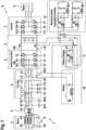
- Fig. 1 shows an electric diagram of the motor and brake drive section of an elevator system including a drive rescue battery 10 and a battery charger 11 for the drive rescue battery 10.
- the motor and brake drive section is supplied with electric AC power in normal operation mode by AC means 2 which supply power over a first phase P1, a second phase P2 and a third phase P3 via a low pass LCL-filter 4 to a frequency converter 8 for driving an electric motor 9 for moving an elevator car of the elevator system.
- the phases P1, P2, P3 provide AC-voltage offset by approximately 120 degrees to each other with respect to ground G.
- An EMI filter may be inserted between the AC means 2 and the LCL-filter 4 as shown in the figure.
- the frequency converter 8 comprises a rectifier circuit 5 for providing a DC supply voltage, a capacitive intermediate device 6 for leveling the DC supply voltage, and an output inverter 7 for generating the AC power supplied to the electric motor 9 as required to control a movement of the elevator car of the elevator system.
- the rectifier circuit 5 is in the form of an Active Front End comprising electronically switchable switching means T1 to T6 with diodes, e.g. diode D6 of IGBT of T6, switched in parallel thereto functioning as freewheeling diodes.
- the electronically switchable switching means T1 to T6 are embodied as IGBTs with the IGBTs T1, T3, and T5 at a low side LS of the DC supply voltage, which may be labeled DC-link minus potential, and the IGBTs T2, T4, and T6 at a high side HS of the DC supply voltage.
- IGBTs T1, T2 are linked to each other and connected to the first phase P1
- IGBTs T3, T4 are linked to each other and connected to the second phase P2
- IGBTs T5, T6 are linked to each other and connected to the third phase P3.
- a corresponding arrangement of electronically switchable switching means as that of the rectifier circuit 5 in the form of IGBTs T7 to T12 is set up in the output inverter 7 for generating the AC-voltage for the motor 9.
- the battery charger 11 is not only connected to the DC plus terminal of the drive rescue battery but also to the high side HS and low side LS of the DC supply voltage.
- the battery charger can therefore also supply DC-voltage to the capacitive intermediate device 6 and to redundant machinery brake controllers and thus brakes of the machinery brake controllers and brakes 12.
- the capacitive intermediate device 6 of the frequency converter 8 can be used to charge the battery charger 11 in a regenerative manner of the frequency converter 8.
- the battery 10 is, in the design shown in Fig. 1 connected between the DC-link minus potential and the third phase P3.
- the battery charger 11 comprises a transformer which is used to lower the DC-link voltage of the capacitive intermediate device 6, also called DC-link, to become suitable for the battery 10 and is connected between the DC-link plus potential and the DC plus terminal of the battery 10.
- Battery charger 11 may comprise one or several switches enabling the control of the charging. In Fig. 1 , such a switch is shown as a transistor at the bottom of the left side of the transformer. Also, the battery 10 may comprise switches enabling the control of power supply with the battery and shown in Fig. 1 as two transistors next to each other.
- the redundant machinery (motor) brake controllers are connected to the DC-link via transformers and supply independently the redundant hoisting machinery (motor) brakes.
- the testing arrangement 1 for testing a capacity of the drive rescue battery 10 comprises the drive rescue battery 10, the first phase P1, the second phase P2 and the third phase P3 of the AC means 2 which are configured to supply power from the AC-means 2 via the low pass LCL-filter 4 to the frequency converter 8 for driving the electric motor 9 in normal operation mode, the LCL-filter 4, the rectifier circuit 5 of the frequency converter 8, a first switching device comprising switches S1, S1', S1" for disconnecting the AC means 2 from the LCL-filter 4, and a second switching device comprising the switch S2 for disconnecting an inductor L2" of the LCL-filter 4 connected to the third phase P3 upstream of the inductor L2" from the rest of the LCL-filter 4.
- the inductor L2" is connected downstream of a capacitor C3 of the LCL-filter 4, which capacitor C3 is connected to the third phase P3.
- the switch S1 is configured to disconnect the LCL-filter 4 from the AC-means 2 downstream of the EMI-filter 3 and connected to the first phase P1.
- the switch S1' is configured to disconnect the LCL-filter 4 from the AC-means 2 downstream of the EMI-filter 3 and connected to the second phase P2.
- Switches S1 and S1' are controlled by switch control unit SC1.
- the switch S1" is configured to disconnect the LCL-filter 4 from the AC-means 2 downstream of the EMI-filter 3 and is connected to the third phase P3.
- Switches S1" and S2 are controlled by switch control unit SC2.
- inductors L2, L2' and capacitors C1, C2 of the LCL-filter 4 wherein L2 and C1 are connected to the first phase P1 and L2# and C2 are connected to the second phase P2, form a test load for testing the capacity of the drive rescue battery 10.
- Inductor L1 of the LCL-filter 4, which is connected to the first phase P1 upstream of the capacitor C1, and inductor L1' of the LCL-filter 4, which is connected to the second phase P2 upstream of the capacitor C2, are not part of a closed electric circuit and thus not operating.
- inductors L2 and L2' are connected via capacitors C1 and C2 in a series connection to the rectifier circuit connected to the first phase Pa1 and the second phase P2 to be supplied with AC-voltage by modulating the gates of the IGBTs T1 to T4 for constituting the test load of the drive rescue battery 10.
- inductor L2 of the LCL-filter 4 which is connected to the first phase P1 and downstream of the capacitor C1 of the LCL-filter 4 connected to the first phase P1 to the rectifier circuit 5
- the inductor L2' of the LCL-filter 4 which is connected to the second phase P2 and downstream of the capacitor C2 of the LCL-filter 4, which is connected to the second phase P2, to the rectifier circuit 5 form the series connection as the test load for the battery 10.
- a third switch S3 is configured to disconnect a DC plus terminal of the drive rescue battery 10 from the inductor L2" of the LCL-filter 4 connected to the third phase P3 upstream of the inductor L2", wherein, if the first switches S1, S1', S1" and the second switch S2 are opened and the third switch S3 is closed, the inductor L2" of the LCL-filter 4 connected to the third phase P3 forms a boost converter storage choke in the rescue operation mode and in the inventive method for testing the capacity of the battery 10.
- the switch S3 is controlled by switch control unit SC3.
- Fig. 2 as an excerpt of Fig. 1 is an electric diagram of the testing arrangement 1 for testing a capacity of the drive rescue battery 10.
- the battery may be used in boost operation as indicated in the figure.
- the switches S1, S1', S1" arranged between the EMI-filter 3 (see Fig. 1 ) and the LCL-filter 4 are opened to disconnect the AC-mains 2 from the test circuit.
- Switch S2 connected to the third phase P3 and shown in Fig. 1 within a boundary of the LCL-filter 4 is opened to disconnect the inductor L1" and the capacitor C3 from the second inductor L2) of the LCL-filter.
- the switch S3 arranged between the LCL-filter 4 and the battery 10 is closed to connect the battery 10 to the AFE forming the rectifier circuit 5.
- the lower side IGBT T5 connected between the third phase P3 and the low side LS of the DC supply voltage, also called DC-link minus potential or DC minus, and the high side parallel diode D6 connected between the third phase P3 and the high side HS of the DC supply voltage, also called DC-link plus potential or DC plus are used with the second inductor L2" of the LCL-filter 4 as a boost converter to supply DC-voltage to the a capacitive intermediate device 6, also called DC-link.
- the first inductor L1" and the capacitor C3 of the third phase P3 are neither acting in this boost operation nor as a test load.
- the inductors L2, L2' and the capacitors C1, C2 of the LCL-filter 4 of the first phase P1 and the second phase P2 are not part of the boost operation but are used as the test load.
- Inductors L1, L1' and capacitors C1, C2 are series connected in the chain: L2 of the first phase P1, C1 of the first phase P1, C2 of the second phase P2, and L2' of the second phase P2.
- Inductors L1 of the first phase P1, L1' of the second phase P2, and L1" of the third phase P3 are not used in boost operation or as the test load of the drive recue battery 10.
- Fig. 3 is a simplified electric diagram of the testing arrangement 1 of Fig. 2 for driving the electric motor 9 of the elevator system in a rescue operation mode according to the invention.
- the electric diagram of Fig. 2 can be simplified into that of Fig. 3 .
- Modulation of the gates G1 of IGBT 1 and G2 of IGBT T2, each of which is connected to the first phase P1, and of the gates G3 of IGBT 3 and G4 of IGBT T4, each of which is connected to the second phase P2 results in providing AC-voltage for the test load being the series connection of inductor L2, capacitor C1, capacitor C2, and inductor L2'.
- a control unit of the frequency converter 8 may be responsible for initiating, executing and analysing the testing without the intervention of an elevator controller.
- the motor 9 (see Fig. 1 ) must not run during the test of the capacity of the drive rescue battery 10. During this test only the two phases P1 and P2 can be modulated to provide constant AC-discharge power and the third phase P3 can be used for the boost operation of the battery 10.
- Inductor L2" is essential only for the boost operation of the battery 10, not for the test load operation of the series connection of L2, C1, C2, L2'. In case the battery 10 is connected in some other way to the DC-link, e.g.
- the inventive method of testing the capacity of the battery 10 by using the devices L2, C1, C2, L2" of the LCL-filter 4 as a test load of the battery 10 may not require the battery to operate in the boost operation mode.
- Fig. 4 is a set of three timing charts over 1 ms according to another exemplary embodiment of the invention, wherein the upper chart shows pulse width modulation sequences of the gates G1, G2 of the IGBTs T1, T2 of the rectifier circuit 5 connected to the first phase P1.
- the medium chart shows pulse width modulation sequences of gates G3, G4 of the IGBTs T3, T4 of the rectifier circuit 5 connected to the second phase P2.
- the lower chart shows the resulting AC-voltage 42 generated by the pulse width modulation sequences of the gates G1 to G4 of the IGBTs T1 to T4 over the two inductors L2, L2' and two capacitors C1, C2 of the LCL-filter 4 as a test load of the drive rescue battery 10.
- a value for each of the capacitors C1, C2 is 10 ⁇ F and for each of the inductors L2, L2' is 830 ⁇ H (no load). Other values are possible.
- the horizontal time scale 40 is the same for all charts ranging over 1 ms from 0.099 to 0.1 seconds.
- the pulse width modulations of each of the gates G1 and G2 of the IFGBTs T1 and T2, which according to each of figures 1 , 2 , and 3 are the low side and high side electronically switchable switching means linked to each other and connected to the first phase P1, are shown in the upper chart on a scale of zero to 1 as a voltage stroke 41 applied to the respective gate. At zero, there is no voltage applied to the respective gate such that the IGBT is not conducting leading to an open switch. At 1, the full voltage is applied to the gate such that the IGBT is conducting from source to drain leading to a closed switch.
- each of the gates G3, G4 of the IFGBTs T3, T4 are the low side and high side electronically switchable switching means linked to each other and connected to the second phase P2 are shown in the medium chart with a stroke 41 ranging again from zero to 1.
- the lower chart shows the resulting AC-voltage full wave test load including a positive half wave from 0.099 s to 0.09955 s with a maximum of 230 V shown on the scale 42 and a subsequent negative half wave from 0.09955 s to 0.1 s with a negative maximum of -230 V.
- the DC-voltage supplied by the battery 10 is boost converted into the high side HS and the low side LS of the DC supply voltage (DC-link plus potential and DC-link minus potential).
- the gates G1 to G4 of IGBTs T1 to T4 are pulse width modulated to generate an AC-voltage over inductor L2, capacitors C1, C2, and inductor L2' connected in series.
- the resulting test load of the battery 10 is for example 230 V, 10 A at 1000 Hz.
- Intervals in time 45, 45', 45", 45′′′, 45 ⁇ indicate states in which the high side IGBT T2 connected to the first phase P11 and the low side IGBT T3 connected to the second phase P2 are conducting for current to flow technically from the high side to the low side of the DC supply voltage. IGBTs T1, T4 are not conducting and therefore do not have an impact on the current flow.
- time intervals 47, 47', 47", 47′′′, 47 ⁇ states are indicated in which the low side IGBT T1 connected to the first phase P1 and the high side IGBT T4 connected to the second phase P11 and are conducting for current to flow technically from the low side to the high side of the DC supply voltage, i.e. the opposite direction of the current which is flowing during time intervals 45 to 45 ⁇ .
- IGBTs T2, T3 are not conducting when IGBTs T1, T4 are conducting and thus do not have an impact on current flow.
- During the time intervals 47 to 75 ⁇ there is a negative voltage in the range 48 ranging between approximately -200 and -230 V to be supplied by the battery 10.
- the operation of the gates G1 to G4 comprises according to Fig.
- the fundamental frequency of 1000 Hz and voltage level of 230 V over the LCL-filter capacitors C1, C2 are controlled to keep a constant discharge power by using a P (Proportional) or PI (Proportional Integral) controller.
- a PID (Proportional Integral Differential) controller is also possible.
- First a discharge power reference value is set to e.g. 200 W.
- a battery current and voltage measurement is utilized to acquire a (real) discharge power value, which is subtracted from the discharge power reference value to determine an error value to controller.
- the fundamental frequency or voltage over the capacitors C1, C2 is increased, decreased or kept constant until the next battery current and voltage measurement.
- the invention provides a method for testing a capacity of a drive rescue battery, wherein in normal operation of the transportation system, e.g. elevator system, a first switching device comprising first switches S1, S1', S1" and a second switching device comprising a second switch S2 are closed and a third switching device of a third switch S3 is open.
- a first switching device comprising first switches S1, S1', S1" and a second switching device comprising a second switch S2 are closed and a third switching device of a third switch S3 is open.
- first and second switching devices are opened.
- the third switch device is closed.
- a battery voltage is boosted with a low side electronically switchable switching means T5 connected to a third phase P3 of a rectifier circuit 5 to supply a capacitive intermediate device 6 of a frequency converter 8 for leveling the DC supply voltage and electronically switchable switching means T1 to T4 of the rectifier circuit 5 connected to first and second phases P1, P2 are modulated to supply AC-voltage to a series connection of passive components of an LCL-filter 4 of an inductor L2 connected to the first phase P1, capacitor C1 connected to the first phase P1, capacitor C2 connected to the second phase P2, and inductor L2' connected to the second phase P2.
- the series connection forms a known impedance and the supplied power to that impedance is known based on e.g. the modulation of the electronically switchable switching means T1 to T4 of the rectifier circuit 5 the power discharged from the battery 10 may be determined.
Landscapes
- Physics & Mathematics (AREA)
- General Physics & Mathematics (AREA)
- Charge And Discharge Circuits For Batteries Or The Like (AREA)
- Inverter Devices (AREA)
Priority Applications (7)
| Application Number | Priority Date | Filing Date | Title |
|---|---|---|---|
| FIEP19204757.9T FI3812331T3 (fi) | 2019-10-23 | 2019-10-23 | Menetelmä turva-akun kapasiteetin testaamiseksi kuljetusjärjestelmän ohjelmisto-ohjelmassa ja testausjärjestelyssä |
| DK19204757.9T DK3812331T3 (da) | 2019-10-23 | 2019-10-23 | Fremgangsmåde til test af en kapacitet af et drevreservebatteri i et transportsystem, testanordning og computerprogramprodukt |
| EP19204757.9A EP3812331B1 (en) | 2019-10-23 | 2019-10-23 | Method for testing a capacity of a drive rescue battery of a transportation system, testing arrangement and computer program product |
| RU2020129462A RU2020129462A (ru) | 2019-10-23 | 2020-09-07 | Способ проверки емкости аварийного аккумулятора привода системы транспортировки, программный продукт и проверочное устройство |
| US17/021,394 US11567138B2 (en) | 2019-10-23 | 2020-09-15 | Method for testing a capacity of a drive rescue battery of a transportation system, software program, and testing arrangement |
| AU2020239618A AU2020239618A1 (en) | 2019-10-23 | 2020-09-21 | Method for testing a capacity of a drive rescue battery of a transportation system, software program, and testing arrangement |
| CN202011119673.0A CN112698226B (zh) | 2019-10-23 | 2020-10-19 | 用于测试运输系统的驱动救援电池的容量的方法 |
Applications Claiming Priority (1)
| Application Number | Priority Date | Filing Date | Title |
|---|---|---|---|
| EP19204757.9A EP3812331B1 (en) | 2019-10-23 | 2019-10-23 | Method for testing a capacity of a drive rescue battery of a transportation system, testing arrangement and computer program product |
Publications (2)
| Publication Number | Publication Date |
|---|---|
| EP3812331A1 EP3812331A1 (en) | 2021-04-28 |
| EP3812331B1 true EP3812331B1 (en) | 2024-02-14 |
Family
ID=68342593
Family Applications (1)
| Application Number | Title | Priority Date | Filing Date |
|---|---|---|---|
| EP19204757.9A Active EP3812331B1 (en) | 2019-10-23 | 2019-10-23 | Method for testing a capacity of a drive rescue battery of a transportation system, testing arrangement and computer program product |
Country Status (7)
| Country | Link |
|---|---|
| US (1) | US11567138B2 (da) |
| EP (1) | EP3812331B1 (da) |
| CN (1) | CN112698226B (da) |
| AU (1) | AU2020239618A1 (da) |
| DK (1) | DK3812331T3 (da) |
| FI (1) | FI3812331T3 (da) |
| RU (1) | RU2020129462A (da) |
Families Citing this family (6)
| Publication number | Priority date | Publication date | Assignee | Title |
|---|---|---|---|---|
| EP3954642B1 (en) * | 2020-08-11 | 2024-10-02 | KONE Corporation | Method and system for an automatic rescue operation of an elevator car |
| EP4191265A1 (de) * | 2021-12-01 | 2023-06-07 | dSPACE GmbH | Testanordnung zum test eines leistungselektronischen steuergeräts und leistungselektronik-modul für eine solche testanordnung |
| CN114994562A (zh) * | 2022-06-28 | 2022-09-02 | 深圳市麦格米特驱动技术有限公司 | 一种测试电路、测试方法及测试设备 |
| US20240120749A1 (en) * | 2022-10-05 | 2024-04-11 | Champion Power Equipment, Inc. | System and method for determining available battery level to an expandable power station |
| DE102022131851A1 (de) * | 2022-12-09 | 2024-06-20 | Dspace Gmbh | Testanordnung zum Test eines leistungselektronischen Steuergeräts |
| CN117185062A (zh) * | 2023-09-04 | 2023-12-08 | 深圳市吉炫龙科技有限公司 | 一种电梯控制系统 |
Family Cites Families (8)
| Publication number | Priority date | Publication date | Assignee | Title |
|---|---|---|---|---|
| DE19546420C1 (de) * | 1995-12-12 | 1997-04-10 | Siemens Ag | Unterbrechungsfreie Stromversorgungseinrichtung |
| CN101599656A (zh) * | 2009-04-16 | 2009-12-09 | 中国石油大学(华东) | 一种动力蓄电池组测试系统用充放电机 |
| CN203851060U (zh) * | 2014-05-10 | 2014-09-24 | 湖北德普电气股份有限公司 | 一种动力电池模拟装置 |
| CN104215911B (zh) * | 2014-08-26 | 2017-04-05 | 广东易事特电源股份有限公司 | Ups电池自我检测电路及检测方法 |
| DK3290375T3 (da) * | 2016-08-29 | 2019-09-30 | Kone Corp | Elevator |
| CN107677964B (zh) * | 2017-08-09 | 2019-11-22 | 杭州威衡科技有限公司 | 一种新能源汽车电机电池模拟测试方法 |
| EP3483106B1 (en) * | 2017-11-08 | 2020-07-15 | KONE Corporation | Elevator automatic and manual rescue operation |
| CN111465568B (zh) * | 2018-04-13 | 2021-07-13 | 三菱电机大楼技术服务株式会社 | 电梯的电池诊断装置 |
-
2019
- 2019-10-23 FI FIEP19204757.9T patent/FI3812331T3/fi active
- 2019-10-23 DK DK19204757.9T patent/DK3812331T3/da active
- 2019-10-23 EP EP19204757.9A patent/EP3812331B1/en active Active
-
2020
- 2020-09-07 RU RU2020129462A patent/RU2020129462A/ru unknown
- 2020-09-15 US US17/021,394 patent/US11567138B2/en active Active
- 2020-09-21 AU AU2020239618A patent/AU2020239618A1/en active Pending
- 2020-10-19 CN CN202011119673.0A patent/CN112698226B/zh active Active
Also Published As
| Publication number | Publication date |
|---|---|
| US20210123976A1 (en) | 2021-04-29 |
| FI3812331T3 (fi) | 2024-04-10 |
| RU2020129462A (ru) | 2022-03-25 |
| US11567138B2 (en) | 2023-01-31 |
| CN112698226B (zh) | 2026-04-28 |
| AU2020239618A1 (en) | 2021-05-13 |
| DK3812331T3 (da) | 2024-04-08 |
| EP3812331A1 (en) | 2021-04-28 |
| CN112698226A (zh) | 2021-04-23 |
Similar Documents
| Publication | Publication Date | Title |
|---|---|---|
| EP3812331B1 (en) | Method for testing a capacity of a drive rescue battery of a transportation system, testing arrangement and computer program product | |
| CA2554269C (en) | Energy efficient variable speed drive for elevator systems | |
| US8789659B2 (en) | System and method for operating a motor during normal and power failure conditions | |
| JP2010538929A (ja) | 救助運転回路を備えるエレベータ駆動システム | |
| US10598738B2 (en) | Method for maintenance of a frequency converter and software program realizing the same | |
| CN101434359B (zh) | 电梯的供电系统 | |
| CN101282898A (zh) | 升降机电源系统 | |
| US8714313B2 (en) | Electrical power system with power limiting to network | |
| CN108792859B (zh) | 基于电梯电源装置实现电梯系统供电的方法及装置和系统 | |
| CN101687605B (zh) | 运输系统的电源设备 | |
| CN109748166A (zh) | 电梯 | |
| EP2716588B1 (en) | Control device for elevator | |
| JP2018154427A (ja) | 乗客コンベア | |
| CN101316782A (zh) | 升降机自动着床装置 | |
| HK40045050A (en) | Method for testing a capacity of a drive rescue battery of a transportation system, software program, and testing arrangement | |
| JP2888362B2 (ja) | エレベーターの停電時運転装置 | |
| HK40011018A (en) | Method for maintenance of a frequency converter and software program realizing the same | |
| JPS5980195A (ja) | エレベ−タ−制御装置 | |
| JPS6319429B2 (da) | ||
| HK1148724A (en) | Automatic rescue operation for a regenerative drive system | |
| JPS61112537A (ja) | エレベ−タ−制御装置 | |
| JPH01248968A (ja) | 電力変換装置 | |
| HK1124300B (en) | Elevator power system |
Legal Events
| Date | Code | Title | Description |
|---|---|---|---|
| PUAI | Public reference made under article 153(3) epc to a published international application that has entered the european phase |
Free format text: ORIGINAL CODE: 0009012 |
|
| STAA | Information on the status of an ep patent application or granted ep patent |
Free format text: STATUS: THE APPLICATION HAS BEEN PUBLISHED |
|
| AK | Designated contracting states |
Kind code of ref document: A1 Designated state(s): AL AT BE BG CH CY CZ DE DK EE ES FI FR GB GR HR HU IE IS IT LI LT LU LV MC MK MT NL NO PL PT RO RS SE SI SK SM TR |
|
| AX | Request for extension of the european patent |
Extension state: BA ME |
|
| STAA | Information on the status of an ep patent application or granted ep patent |
Free format text: STATUS: REQUEST FOR EXAMINATION WAS MADE |
|
| 17P | Request for examination filed |
Effective date: 20211015 |
|
| RBV | Designated contracting states (corrected) |
Designated state(s): AL AT BE BG CH CY CZ DE DK EE ES FI FR GB GR HR HU IE IS IT LI LT LU LV MC MK MT NL NO PL PT RO RS SE SI SK SM TR |
|
| STAA | Information on the status of an ep patent application or granted ep patent |
Free format text: STATUS: EXAMINATION IS IN PROGRESS |
|
| 17Q | First examination report despatched |
Effective date: 20221019 |
|
| P01 | Opt-out of the competence of the unified patent court (upc) registered |
Effective date: 20230525 |
|
| GRAP | Despatch of communication of intention to grant a patent |
Free format text: ORIGINAL CODE: EPIDOSNIGR1 |
|
| STAA | Information on the status of an ep patent application or granted ep patent |
Free format text: STATUS: GRANT OF PATENT IS INTENDED |
|
| INTG | Intention to grant announced |
Effective date: 20230926 |
|
| GRAS | Grant fee paid |
Free format text: ORIGINAL CODE: EPIDOSNIGR3 |
|
| GRAA | (expected) grant |
Free format text: ORIGINAL CODE: 0009210 |
|
| STAA | Information on the status of an ep patent application or granted ep patent |
Free format text: STATUS: THE PATENT HAS BEEN GRANTED |
|
| AK | Designated contracting states |
Kind code of ref document: B1 Designated state(s): AL AT BE BG CH CY CZ DE DK EE ES FI FR GB GR HR HU IE IS IT LI LT LU LV MC MK MT NL NO PL PT RO RS SE SI SK SM TR |
|
| REG | Reference to a national code |
Ref country code: GB Ref legal event code: FG4D |
|
| REG | Reference to a national code |
Ref country code: CH Ref legal event code: EP |
|
| REG | Reference to a national code |
Ref country code: DE Ref legal event code: R096 Ref document number: 602019046419 Country of ref document: DE |
|
| REG | Reference to a national code |
Ref country code: IE Ref legal event code: FG4D |
|
| REG | Reference to a national code |
Ref country code: DK Ref legal event code: T3 Effective date: 20240405 |
|
| REG | Reference to a national code |
Ref country code: FI Ref legal event code: FGE |
|
| REG | Reference to a national code |
Ref country code: LT Ref legal event code: MG9D |
|
| REG | Reference to a national code |
Ref country code: NL Ref legal event code: MP Effective date: 20240214 |
|
| PG25 | Lapsed in a contracting state [announced via postgrant information from national office to epo] |
Ref country code: IS Free format text: LAPSE BECAUSE OF FAILURE TO SUBMIT A TRANSLATION OF THE DESCRIPTION OR TO PAY THE FEE WITHIN THE PRESCRIBED TIME-LIMIT Effective date: 20240614 |
|
| PG25 | Lapsed in a contracting state [announced via postgrant information from national office to epo] |
Ref country code: LT Free format text: LAPSE BECAUSE OF FAILURE TO SUBMIT A TRANSLATION OF THE DESCRIPTION OR TO PAY THE FEE WITHIN THE PRESCRIBED TIME-LIMIT Effective date: 20240214 |
|
| PG25 | Lapsed in a contracting state [announced via postgrant information from national office to epo] |
Ref country code: GR Free format text: LAPSE BECAUSE OF FAILURE TO SUBMIT A TRANSLATION OF THE DESCRIPTION OR TO PAY THE FEE WITHIN THE PRESCRIBED TIME-LIMIT Effective date: 20240515 |
|
| REG | Reference to a national code |
Ref country code: AT Ref legal event code: MK05 Ref document number: 1656898 Country of ref document: AT Kind code of ref document: T Effective date: 20240214 |
|
| PG25 | Lapsed in a contracting state [announced via postgrant information from national office to epo] |
Ref country code: HR Free format text: LAPSE BECAUSE OF FAILURE TO SUBMIT A TRANSLATION OF THE DESCRIPTION OR TO PAY THE FEE WITHIN THE PRESCRIBED TIME-LIMIT Effective date: 20240214 Ref country code: RS Free format text: LAPSE BECAUSE OF FAILURE TO SUBMIT A TRANSLATION OF THE DESCRIPTION OR TO PAY THE FEE WITHIN THE PRESCRIBED TIME-LIMIT Effective date: 20240514 Ref country code: NL Free format text: LAPSE BECAUSE OF FAILURE TO SUBMIT A TRANSLATION OF THE DESCRIPTION OR TO PAY THE FEE WITHIN THE PRESCRIBED TIME-LIMIT Effective date: 20240214 |
|
| PG25 | Lapsed in a contracting state [announced via postgrant information from national office to epo] |
Ref country code: ES Free format text: LAPSE BECAUSE OF FAILURE TO SUBMIT A TRANSLATION OF THE DESCRIPTION OR TO PAY THE FEE WITHIN THE PRESCRIBED TIME-LIMIT Effective date: 20240214 |
|
| PG25 | Lapsed in a contracting state [announced via postgrant information from national office to epo] |
Ref country code: AT Free format text: LAPSE BECAUSE OF FAILURE TO SUBMIT A TRANSLATION OF THE DESCRIPTION OR TO PAY THE FEE WITHIN THE PRESCRIBED TIME-LIMIT Effective date: 20240214 |
|
| PG25 | Lapsed in a contracting state [announced via postgrant information from national office to epo] |
Ref country code: RS Free format text: LAPSE BECAUSE OF FAILURE TO SUBMIT A TRANSLATION OF THE DESCRIPTION OR TO PAY THE FEE WITHIN THE PRESCRIBED TIME-LIMIT Effective date: 20240514 Ref country code: NO Free format text: LAPSE BECAUSE OF FAILURE TO SUBMIT A TRANSLATION OF THE DESCRIPTION OR TO PAY THE FEE WITHIN THE PRESCRIBED TIME-LIMIT Effective date: 20240514 Ref country code: NL Free format text: LAPSE BECAUSE OF FAILURE TO SUBMIT A TRANSLATION OF THE DESCRIPTION OR TO PAY THE FEE WITHIN THE PRESCRIBED TIME-LIMIT Effective date: 20240214 Ref country code: LT Free format text: LAPSE BECAUSE OF FAILURE TO SUBMIT A TRANSLATION OF THE DESCRIPTION OR TO PAY THE FEE WITHIN THE PRESCRIBED TIME-LIMIT Effective date: 20240214 Ref country code: IS Free format text: LAPSE BECAUSE OF FAILURE TO SUBMIT A TRANSLATION OF THE DESCRIPTION OR TO PAY THE FEE WITHIN THE PRESCRIBED TIME-LIMIT Effective date: 20240614 Ref country code: HR Free format text: LAPSE BECAUSE OF FAILURE TO SUBMIT A TRANSLATION OF THE DESCRIPTION OR TO PAY THE FEE WITHIN THE PRESCRIBED TIME-LIMIT Effective date: 20240214 Ref country code: GR Free format text: LAPSE BECAUSE OF FAILURE TO SUBMIT A TRANSLATION OF THE DESCRIPTION OR TO PAY THE FEE WITHIN THE PRESCRIBED TIME-LIMIT Effective date: 20240515 Ref country code: ES Free format text: LAPSE BECAUSE OF FAILURE TO SUBMIT A TRANSLATION OF THE DESCRIPTION OR TO PAY THE FEE WITHIN THE PRESCRIBED TIME-LIMIT Effective date: 20240214 Ref country code: BG Free format text: LAPSE BECAUSE OF FAILURE TO SUBMIT A TRANSLATION OF THE DESCRIPTION OR TO PAY THE FEE WITHIN THE PRESCRIBED TIME-LIMIT Effective date: 20240214 Ref country code: AT Free format text: LAPSE BECAUSE OF FAILURE TO SUBMIT A TRANSLATION OF THE DESCRIPTION OR TO PAY THE FEE WITHIN THE PRESCRIBED TIME-LIMIT Effective date: 20240214 |
|
| PG25 | Lapsed in a contracting state [announced via postgrant information from national office to epo] |
Ref country code: PL Free format text: LAPSE BECAUSE OF FAILURE TO SUBMIT A TRANSLATION OF THE DESCRIPTION OR TO PAY THE FEE WITHIN THE PRESCRIBED TIME-LIMIT Effective date: 20240214 Ref country code: PT Free format text: LAPSE BECAUSE OF FAILURE TO SUBMIT A TRANSLATION OF THE DESCRIPTION OR TO PAY THE FEE WITHIN THE PRESCRIBED TIME-LIMIT Effective date: 20240614 |
|
| PG25 | Lapsed in a contracting state [announced via postgrant information from national office to epo] |
Ref country code: SE Free format text: LAPSE BECAUSE OF FAILURE TO SUBMIT A TRANSLATION OF THE DESCRIPTION OR TO PAY THE FEE WITHIN THE PRESCRIBED TIME-LIMIT Effective date: 20240214 Ref country code: PT Free format text: LAPSE BECAUSE OF FAILURE TO SUBMIT A TRANSLATION OF THE DESCRIPTION OR TO PAY THE FEE WITHIN THE PRESCRIBED TIME-LIMIT Effective date: 20240614 Ref country code: PL Free format text: LAPSE BECAUSE OF FAILURE TO SUBMIT A TRANSLATION OF THE DESCRIPTION OR TO PAY THE FEE WITHIN THE PRESCRIBED TIME-LIMIT Effective date: 20240214 Ref country code: LV Free format text: LAPSE BECAUSE OF FAILURE TO SUBMIT A TRANSLATION OF THE DESCRIPTION OR TO PAY THE FEE WITHIN THE PRESCRIBED TIME-LIMIT Effective date: 20240214 |
|
| PG25 | Lapsed in a contracting state [announced via postgrant information from national office to epo] |
Ref country code: SM Free format text: LAPSE BECAUSE OF FAILURE TO SUBMIT A TRANSLATION OF THE DESCRIPTION OR TO PAY THE FEE WITHIN THE PRESCRIBED TIME-LIMIT Effective date: 20240214 |
|
| PG25 | Lapsed in a contracting state [announced via postgrant information from national office to epo] |
Ref country code: CZ Free format text: LAPSE BECAUSE OF FAILURE TO SUBMIT A TRANSLATION OF THE DESCRIPTION OR TO PAY THE FEE WITHIN THE PRESCRIBED TIME-LIMIT Effective date: 20240214 Ref country code: EE Free format text: LAPSE BECAUSE OF FAILURE TO SUBMIT A TRANSLATION OF THE DESCRIPTION OR TO PAY THE FEE WITHIN THE PRESCRIBED TIME-LIMIT Effective date: 20240214 |
|
| PG25 | Lapsed in a contracting state [announced via postgrant information from national office to epo] |
Ref country code: SK Free format text: LAPSE BECAUSE OF FAILURE TO SUBMIT A TRANSLATION OF THE DESCRIPTION OR TO PAY THE FEE WITHIN THE PRESCRIBED TIME-LIMIT Effective date: 20240214 |
|
| PG25 | Lapsed in a contracting state [announced via postgrant information from national office to epo] |
Ref country code: SM Free format text: LAPSE BECAUSE OF FAILURE TO SUBMIT A TRANSLATION OF THE DESCRIPTION OR TO PAY THE FEE WITHIN THE PRESCRIBED TIME-LIMIT Effective date: 20240214 Ref country code: SK Free format text: LAPSE BECAUSE OF FAILURE TO SUBMIT A TRANSLATION OF THE DESCRIPTION OR TO PAY THE FEE WITHIN THE PRESCRIBED TIME-LIMIT Effective date: 20240214 Ref country code: RO Free format text: LAPSE BECAUSE OF FAILURE TO SUBMIT A TRANSLATION OF THE DESCRIPTION OR TO PAY THE FEE WITHIN THE PRESCRIBED TIME-LIMIT Effective date: 20240214 Ref country code: EE Free format text: LAPSE BECAUSE OF FAILURE TO SUBMIT A TRANSLATION OF THE DESCRIPTION OR TO PAY THE FEE WITHIN THE PRESCRIBED TIME-LIMIT Effective date: 20240214 Ref country code: CZ Free format text: LAPSE BECAUSE OF FAILURE TO SUBMIT A TRANSLATION OF THE DESCRIPTION OR TO PAY THE FEE WITHIN THE PRESCRIBED TIME-LIMIT Effective date: 20240214 |
|
| REG | Reference to a national code |
Ref country code: DE Ref legal event code: R097 Ref document number: 602019046419 Country of ref document: DE |
|
| PG25 | Lapsed in a contracting state [announced via postgrant information from national office to epo] |
Ref country code: IT Free format text: LAPSE BECAUSE OF FAILURE TO SUBMIT A TRANSLATION OF THE DESCRIPTION OR TO PAY THE FEE WITHIN THE PRESCRIBED TIME-LIMIT Effective date: 20240214 |
|
| PLBE | No opposition filed within time limit |
Free format text: ORIGINAL CODE: 0009261 |
|
| STAA | Information on the status of an ep patent application or granted ep patent |
Free format text: STATUS: NO OPPOSITION FILED WITHIN TIME LIMIT |
|
| PG25 | Lapsed in a contracting state [announced via postgrant information from national office to epo] |
Ref country code: IT Free format text: LAPSE BECAUSE OF FAILURE TO SUBMIT A TRANSLATION OF THE DESCRIPTION OR TO PAY THE FEE WITHIN THE PRESCRIBED TIME-LIMIT Effective date: 20240214 |
|
| 26N | No opposition filed |
Effective date: 20241115 |
|
| PG25 | Lapsed in a contracting state [announced via postgrant information from national office to epo] |
Ref country code: SI Free format text: LAPSE BECAUSE OF FAILURE TO SUBMIT A TRANSLATION OF THE DESCRIPTION OR TO PAY THE FEE WITHIN THE PRESCRIBED TIME-LIMIT Effective date: 20240214 |
|
| REG | Reference to a national code |
Ref country code: CH Ref legal event code: PL |
|
| PG25 | Lapsed in a contracting state [announced via postgrant information from national office to epo] |
Ref country code: MC Free format text: LAPSE BECAUSE OF FAILURE TO SUBMIT A TRANSLATION OF THE DESCRIPTION OR TO PAY THE FEE WITHIN THE PRESCRIBED TIME-LIMIT Effective date: 20240214 |
|
| PG25 | Lapsed in a contracting state [announced via postgrant information from national office to epo] |
Ref country code: BE Free format text: LAPSE BECAUSE OF NON-PAYMENT OF DUE FEES Effective date: 20241031 Ref country code: LU Free format text: LAPSE BECAUSE OF NON-PAYMENT OF DUE FEES Effective date: 20241023 |
|
| PG25 | Lapsed in a contracting state [announced via postgrant information from national office to epo] |
Ref country code: CH Free format text: LAPSE BECAUSE OF NON-PAYMENT OF DUE FEES Effective date: 20241031 |
|
| REG | Reference to a national code |
Ref country code: BE Ref legal event code: MM Effective date: 20241031 |
|
| PG25 | Lapsed in a contracting state [announced via postgrant information from national office to epo] |
Ref country code: IE Free format text: LAPSE BECAUSE OF NON-PAYMENT OF DUE FEES Effective date: 20241023 |
|
| PGFP | Annual fee paid to national office [announced via postgrant information from national office to epo] |
Ref country code: DE Payment date: 20251021 Year of fee payment: 7 |
|
| PGFP | Annual fee paid to national office [announced via postgrant information from national office to epo] |
Ref country code: GB Payment date: 20251022 Year of fee payment: 7 |
|
| PGFP | Annual fee paid to national office [announced via postgrant information from national office to epo] |
Ref country code: FI Payment date: 20251028 Year of fee payment: 7 Ref country code: DK Payment date: 20251027 Year of fee payment: 7 |
|
| PGFP | Annual fee paid to national office [announced via postgrant information from national office to epo] |
Ref country code: FR Payment date: 20251030 Year of fee payment: 7 |
|
| PG25 | Lapsed in a contracting state [announced via postgrant information from national office to epo] |
Ref country code: CY Free format text: LAPSE BECAUSE OF FAILURE TO SUBMIT A TRANSLATION OF THE DESCRIPTION OR TO PAY THE FEE WITHIN THE PRESCRIBED TIME-LIMIT; INVALID AB INITIO Effective date: 20191023 |
|
| PG25 | Lapsed in a contracting state [announced via postgrant information from national office to epo] |
Ref country code: HU Free format text: LAPSE BECAUSE OF FAILURE TO SUBMIT A TRANSLATION OF THE DESCRIPTION OR TO PAY THE FEE WITHIN THE PRESCRIBED TIME-LIMIT; INVALID AB INITIO Effective date: 20191023 |