EP3812241A1 - Steering column device - Google Patents
Steering column device Download PDFInfo
- Publication number
- EP3812241A1 EP3812241A1 EP20203345.2A EP20203345A EP3812241A1 EP 3812241 A1 EP3812241 A1 EP 3812241A1 EP 20203345 A EP20203345 A EP 20203345A EP 3812241 A1 EP3812241 A1 EP 3812241A1
- Authority
- EP
- European Patent Office
- Prior art keywords
- steering column
- vehicle body
- tilt bolt
- side wall
- collar
- Prior art date
- Legal status (The legal status is an assumption and is not a legal conclusion. Google has not performed a legal analysis and makes no representation as to the accuracy of the status listed.)
- Granted
Links
Images


Classifications
-
- B—PERFORMING OPERATIONS; TRANSPORTING
- B62—LAND VEHICLES FOR TRAVELLING OTHERWISE THAN ON RAILS
- B62D—MOTOR VEHICLES; TRAILERS
- B62D1/00—Steering controls, i.e. means for initiating a change of direction of the vehicle
- B62D1/02—Steering controls, i.e. means for initiating a change of direction of the vehicle vehicle-mounted
- B62D1/16—Steering columns
- B62D1/18—Steering columns yieldable or adjustable, e.g. tiltable
- B62D1/184—Mechanisms for locking columns at selected positions
-
- B—PERFORMING OPERATIONS; TRANSPORTING
- B62—LAND VEHICLES FOR TRAVELLING OTHERWISE THAN ON RAILS
- B62D—MOTOR VEHICLES; TRAILERS
- B62D1/00—Steering controls, i.e. means for initiating a change of direction of the vehicle
- B62D1/02—Steering controls, i.e. means for initiating a change of direction of the vehicle vehicle-mounted
- B62D1/16—Steering columns
- B62D1/18—Steering columns yieldable or adjustable, e.g. tiltable
- B62D1/19—Steering columns yieldable or adjustable, e.g. tiltable incorporating energy-absorbing arrangements, e.g. by being yieldable or collapsible
- B62D1/195—Yieldable supports for the steering column
Definitions
- the invention relates to a steering column device.
- a steering column device has a mount bracket fixed to a vehicle body and having a pair of side wall portions, and a steering column constituted by fitting an upper tube and a lower tube to each other and disposed between the side wall portions so as to extend in a front-rear direction of the vehicle body (for example, Japanese Unexamined Patent Application Publication No. 8-295251 ( JP 8-295251 A )).
- the steering column device includes a distance bracket provided on the upper tube of the steering column and having a pair of sliding contact walls, and a tilt bolt extending through the side wall portions and the sliding contact walls.
- the side wall portions of the mount bracket support the steering column such that the steering column is movable in the tilt direction.
- the steering column device described above is configured such that, when a load is applied to the steering column at the time of a secondary collision, the upper tube moves toward the front of the vehicle body along the tube axial direction so that the steering column is contracted to absorb the energy due to a collision load.
- a force in a fastening releasing direction of a lever may act on the tilt bolt from the distance bracket or from the bending plate provided on the distance bracket.
- the steering column device includes: a mount bracket fixed to a vehicle body and including a pair of side wall portions; a steering column constituted by fitting an upper tube and a lower tube to each other; a distance bracket provided on the upper tube and including a pair of sliding contact walls; a tilt bolt extending through the side wall portions and the sliding contact walls; and a detachment mechanism configured to detach the steering column from the mount bracket when a load equal to or greater than a set value is applied to the upper tube toward a front of the vehicle body.
- the steering column is disposed between the side wall portions so as to extend in a front-rear direction of the vehicle body.
- the detachment mechanism is configured to contract the steering column by relative movement of the upper tube and the lower tube.
- the detachment mechanism has a slit that is provided on each sliding contact wall of the distance bracket with the tilt bolt inserted through the slit and that has an open end on a rear side in the front-rear direction of the vehicle body, and a collar mounted on an outer circumference of the tilt bolt.
- the collar is mounted on the outer circumference of the tilt bolt with a space between the outer circumference of the tilt bolt and an inner circumference of the collar.
- an arrow FR indicates a front side in a front-rear direction of a vehicle body
- an arrow RR indicates a rear side in the front-rear direction of the vehicle body
- a steering column device 1 according to the present embodiment shown in FIG. 1 is a manual steering column device.
- the steering column device 1 includes a mount bracket 2 fixed to the vehicle body and a steering column (column tube) 3 supported by the mount bracket 2 so as to be pivotable in an up-down direction of the vehicle body (so that a tilt position is adjustable).
- the mount bracket 2 includes a fixed portion 4 fixed to a ceiling surface (not shown) of the vehicle body.
- a pair of side wall portions 5 hangs from the fixed portion 4.
- Each side wall portion 5 has a long hole (tilt long hole) 6 that defines a tilt position adjustment range along the up-down direction of the vehicle body (tilt direction).
- the tilt long hole 6 is composed of an arcuate elongated hole centered on a shaft support portion (not shown).
- the steering column 3 is mainly composed of an upper tube 7 disposed between the side wall portions 5, and a lower tube 8 fitted to the upper tube 7.
- the steering column 3 is provided with a lock mechanism 11 that integrally fastens the mount bracket 2, the upper tube 7, and the lower tube 8.
- the upper tube 7 has a tubular shape, and is disposed between the side wall portions 5 along the front-rear direction of the vehicle body.
- a distance bracket 12 is attached to the outer circumference of the upper tube 7. With the distance bracket 12 sandwiched between the side wall portions 5, the upper tube 7 is held at a desired tilt position.
- the lower tube 8 has a tubular shape, and the upper tube 7 is fitted to the lower tube 8 in the tube axial direction so that the upper tube 7 is provided outward of the lower tube 8 in a radial direction.
- the lower tube 8 is provided with a shaft support portion (not shown) at the front end portion, and the shaft support portion is supported by the vehicle body, whereby the rear end portion of the lower tube 8 pivots in the up-down direction of the vehicle body.
- a steering shaft 13 is supported radially inward of the upper tube 7 and the lower tube 8, and a bracket 14 for mounting a column cover is provided radially outward of the upper tube 7.
- the distance bracket 12 includes a pair of sliding contact walls 15 extending in the up-down direction of the vehicle body and a connecting portion 16 that connects lower edges of the sliding contact walls 15 in a width direction of the vehicle body, thereby having a substantially U-shape.
- the upper edge of each sliding contact wall 15 is fixed to the outer circumference of the upper tube 7.
- each sliding contact wall 15 is provided with a slit 17 extending along the front-rear direction of the vehicle body and having an open end 18 on the rear side in the front-rear direction of the vehicle body.
- the lock mechanism 11 includes a lever 21, a tilt bolt 22, a fixing cam 23, a rotating cam 24, a washer (not shown), and a nut (not shown).
- the tilt bolt 22 extends through the tilt long holes 6 of the side wall portions 5 and the slits 17 of the sliding contact walls 15 along the width direction of the vehicle body, and is supported so as to be rotatable about an axis. Further, the tilt bolt 22 is provided with the lever 21 at an end portion on one end side and the lever 21 is supported by the side wall portion 5 on the one end side. The end portion of the tilt bolt 22 on the other end side extends through the side wall portion 5 on the other end side and is screwed into a nut, and a washer is interposed between the nut and the side wall portion 5 on the other end side. Further, the fixing cam 23 and the rotating cam 24 are arranged at a portion on the tilt bolt 22 located between the lever 21 and the side wall portion 5 on the one end side.
- the fixing cam 23 has an annular shape, the central portion of which the tilt bolt 22 extends through, and is disposed such that a fixing cam surface faces the lever 21. Further, the surface on the opposite side of the fixing cam 23 from the fixing cam surface is fitted in the tilt long hole 6, and the fixing cam 23 is provided so as not to rotate around the tilt bolt 22 and so as to be movable in the tilt long hole 6. Protrusions and recesses are alternately provided on the fixing cam surface in the circumferential direction.
- the rotating cam 24 has an annular shape, the central portion of which the tilt bolt 22 extends through, and is disposed such that a rotating cam surface faces the fixing cam surface.
- the rotating cam 24 is assembled to the lever 21 so as to rotate integrally with the lever 21 about the axis of the tilt bolt 22 together with the tilt bolt 22 extending through the rotating cam 24. Protrusions and recesses are alternately provided on the rotating cam surface in the circumferential direction.
- the steering column device 1 has a detachment mechanism 31 for detaching the steering column 3 from the mount bracket 2 when a load equal to or greater than a set value is applied to the steering column 3.
- the detachment mechanism 31 has the slit 17 provided on each sliding contact wall 15 of the distance bracket 12 with the tilt bolt 22 inserted therethrough and having the open end 18 on the rear side in the front-rear direction of the vehicle body, and a collar 32 mounted on the outer circumference of the tilt bolt 22.
- the collar 32 is a resin collar made of a resin material.
- the collar 32 is loosely fitted to the outer circumference of the tilt bolt 22 so that it can idle around the tilt bolt 22. That is, the collar 32 is mounted on the outer circumference of the tilt bolt 22 with a play (space) between the outer circumference of the tilt bolt 22 and the inner circumference of the collar 32 (see FIG. 4 ).
- the detachment mechanism 31 has a bending plate 33 provided on the distance bracket 12 and for adjusting the load that acts when the tilt bolt 22 is detached from the sliding contact walls 15 along the slits 17 of the distance bracket 12.
- the bending plate 33 has a fixed end portion 34 fixed to the connecting portion 16 of the distance bracket 12, and a bent portion (tongue portion) 35 extending from the fixed end portion 34 and bent upward in the up-down direction of the vehicle body.
- a receiving surface portion (guide) 36 is provided on the mount bracket 2 in order to facilitate the contraction of the steering column 3 due to the relative movement of the upper tube 7 and the lower tube 8, even when the steering column 3 comes into contact with the mount bracket 2.
- the receiving surface portion 36 has an arc shape that protrudes upward in the up-down direction of the vehicle body when viewed in the front-rear direction of the vehicle body (see FIGS. 1 and 3 ).
- the receiving surface portion 36 is provided integrally with the rear portion of the mount bracket 2 in the front-rear direction of the vehicle body.
- the receiving surface portion 36 is configured to have a contact portion 37 that is formed by bending a plate-shaped portion constituting the receiving surface portion 36 toward the rear side of the vehicle body.
- the steering column 3 In order to fix the steering column 3 at a desired position, the steering column 3 is first moved to a desired position in the tilt direction (in the up-down direction of the vehicle body) and the lever 21 is pivotally operated upward in the up-down direction of the vehicle body. By pivotally operating the lever 21 upward in the up-down direction of the vehicle body, the tilt bolt 22 rotates around the axis in the fastening direction.
- the fastening of the steering column 3 to the mount bracket 2 is released.
- the lever 21 is pivotally operated downward in the up-down direction of the vehicle body.
- the tilt bolt 22 rotates around the axis in the fastening releasing direction.
- the tilt bolt 22 rotates in the fastening releasing direction, the protrusions of the fixing cam 23 and the recesses of the rotating cam 24 overlap with each other, reducing the axial dimension.
- the tilt bolt 22 is loosened, the space between the side wall portions 5 is increased, and the pressure contact between the side wall portions 5 and the sliding contact walls 15 of the distance bracket 12 is eliminated, enabling the steering column 3 to move with respect to the mount bracket 2 in the tilt direction.
- the distance bracket 12 moves toward the front of the vehicle body along the slit 17 to be detached from the tilt bolt 22.
- the detachment load that acts when the distance bracket 12 is detached from the tilt bolt 22 is adjusted by the bending plate 33 provided on the distance bracket 12. With the detachment of the distance bracket 12 from the tilt bolt 22 in the detachment mechanism 31, the energy at the time of a secondary collision is absorbed.
- the relative movement of the upper tube 7 and the lower tube 8 causes the steering column 3 to be contracted.
- the sliding resistance of the upper tube 7 with respect to the lower tube 8 when the steering column 3 is contracted also absorbs the energy at the time of a secondary collision.
- the steering column device 1 has the mount bracket 2 fixed to the vehicle body and having the side wall portions 5, and the steering column 3 constituted by fitting the upper tube 7 and the lower tube 8 to each other and disposed between the side wall portions 5 so as to extend in the front-rear direction of the vehicle body.
- the steering column device 1 has the distance bracket 12 provided on the upper tube 7 and having the sliding contact walls 15, and the tilt bolt 22 extending through the side wall portions 5 and the sliding contact walls 15.
- the steering column device 1 has the detachment mechanism 31 for detaching the steering column 3 from the mount bracket 2 by contracting the steering column 3 by the relative movement of the upper tube 7 and the lower tube 8 when a load equal to or greater than a set value is applied to the upper tube 7 toward the front of the vehicle body.
- the detachment mechanism 31 has the slit 17 provided on each sliding contact wall 15 of the distance bracket 12 with the tilt bolt 22 inserted therethrough and having the open end 18 on the rear side in the front-rear direction of the vehicle body, and a collar 32 mounted on the outer circumference of the tilt bolt 22.
- the collar 32 is mounted on the outer circumference of the tilt bolt 22 with a play between the outer circumference of the tilt bolt 22 and the inner circumference of the collar 32.
- the collar 32 is a resin collar made of a resin material.
- the resin collar 32 by utilizing the fact that the rigidity of the resin collar is lower than that of the metal parts such as the distance bracket 12 and the tilt bolt 22, the resin collar can absorb dimensional variations of the metal parts.
- the detachment mechanism 31 has a bending plate 33 provided on the distance bracket 12 and for setting the load that acts when the tilt bolt 22 is detached from the sliding contact walls 15 along the slits 17 of the distance bracket 12.
- the load that acts when the steering column 3 is detached from the mount bracket 2 can be adjusted, and the detachment load at that time can be stabilized.
Landscapes
- Engineering & Computer Science (AREA)
- Chemical & Material Sciences (AREA)
- Combustion & Propulsion (AREA)
- Transportation (AREA)
- Mechanical Engineering (AREA)
- Steering Controls (AREA)
Abstract
Description
- The invention relates to a steering column device.
- A steering column device has a mount bracket fixed to a vehicle body and having a pair of side wall portions, and a steering column constituted by fitting an upper tube and a lower tube to each other and disposed between the side wall portions so as to extend in a front-rear direction of the vehicle body (for example, Japanese Unexamined Patent Application Publication No.
8-295251 JP 8-295251 A - The steering column device described above is configured such that, when a load is applied to the steering column at the time of a secondary collision, the upper tube moves toward the front of the vehicle body along the tube axial direction so that the steering column is contracted to absorb the energy due to a collision load.
- In the steering column device described above, when a load is applied to the steering column at the time of a secondary collision, a force in a fastening releasing direction of a lever may act on the tilt bolt from the distance bracket or from the bending plate provided on the distance bracket.
- According to the invention, it is possible to suppress the tilt bolt from rotating in the fastening releasing direction of the lever to release a tilt lock when a load is applied to the steering column at the time of a secondary collision.
- An aspect of the invention relates to a steering column device. The steering column device includes: a mount bracket fixed to a vehicle body and including a pair of side wall portions; a steering column constituted by fitting an upper tube and a lower tube to each other; a distance bracket provided on the upper tube and including a pair of sliding contact walls; a tilt bolt extending through the side wall portions and the sliding contact walls; and a detachment mechanism configured to detach the steering column from the mount bracket when a load equal to or greater than a set value is applied to the upper tube toward a front of the vehicle body. The steering column is disposed between the side wall portions so as to extend in a front-rear direction of the vehicle body. The detachment mechanism is configured to contract the steering column by relative movement of the upper tube and the lower tube. The detachment mechanism has a slit that is provided on each sliding contact wall of the distance bracket with the tilt bolt inserted through the slit and that has an open end on a rear side in the front-rear direction of the vehicle body, and a collar mounted on an outer circumference of the tilt bolt. The collar is mounted on the outer circumference of the tilt bolt with a space between the outer circumference of the tilt bolt and an inner circumference of the collar.
- With the above configuration, it is possible to suppress the tilt bolt from rotating in the fastening releasing direction of the lever to release the tilt lock when a load is applied to the steering column at the time of a secondary collision.
- Features, advantages, and technical and industrial significance of exemplary embodiments of the invention will be described below with reference to the accompanying drawings, in which like signs denote like elements, and wherein:
-
FIG. 1 is a schematic perspective view showing a steering column device according to an embodiment of the invention; -
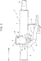
FIG. 2 is a schematic side view showing the steering column device according to the embodiment of the invention; -
FIG. 3 is a schematic perspective view showing a detachment mechanism; and -
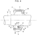
FIG. 4 is a schematic side sectional view showing the detachment mechanism. - Hereinafter, an embodiment of the invention will be described in detail with reference to the drawings.
- In the drawings, an arrow FR indicates a front side in a front-rear direction of a vehicle body, and an arrow RR indicates a rear side in the front-rear direction of the vehicle body.
- A steering column device 1 according to the present embodiment shown in
FIG. 1 is a manual steering column device. As shown inFIGS. 1 and2 , the steering column device 1 includes amount bracket 2 fixed to the vehicle body and a steering column (column tube) 3 supported by themount bracket 2 so as to be pivotable in an up-down direction of the vehicle body (so that a tilt position is adjustable). - The
mount bracket 2 includes a fixedportion 4 fixed to a ceiling surface (not shown) of the vehicle body. A pair ofside wall portions 5 hangs from thefixed portion 4. Eachside wall portion 5 has a long hole (tilt long hole) 6 that defines a tilt position adjustment range along the up-down direction of the vehicle body (tilt direction). The tiltlong hole 6 is composed of an arcuate elongated hole centered on a shaft support portion (not shown). - The
steering column 3 is mainly composed of anupper tube 7 disposed between theside wall portions 5, and alower tube 8 fitted to theupper tube 7. Thesteering column 3 is provided with alock mechanism 11 that integrally fastens themount bracket 2, theupper tube 7, and thelower tube 8. - The
upper tube 7 has a tubular shape, and is disposed between theside wall portions 5 along the front-rear direction of the vehicle body. Adistance bracket 12 is attached to the outer circumference of theupper tube 7. With thedistance bracket 12 sandwiched between theside wall portions 5, theupper tube 7 is held at a desired tilt position. - The
lower tube 8 has a tubular shape, and theupper tube 7 is fitted to thelower tube 8 in the tube axial direction so that theupper tube 7 is provided outward of thelower tube 8 in a radial direction. Thelower tube 8 is provided with a shaft support portion (not shown) at the front end portion, and the shaft support portion is supported by the vehicle body, whereby the rear end portion of thelower tube 8 pivots in the up-down direction of the vehicle body. - A
steering shaft 13 is supported radially inward of theupper tube 7 and thelower tube 8, and abracket 14 for mounting a column cover is provided radially outward of theupper tube 7. - As shown in
FIGS. 3 and4 , thedistance bracket 12 includes a pair of slidingcontact walls 15 extending in the up-down direction of the vehicle body and a connectingportion 16 that connects lower edges of the slidingcontact walls 15 in a width direction of the vehicle body, thereby having a substantially U-shape. The upper edge of each slidingcontact wall 15 is fixed to the outer circumference of theupper tube 7. Further, each slidingcontact wall 15 is provided with aslit 17 extending along the front-rear direction of the vehicle body and having anopen end 18 on the rear side in the front-rear direction of the vehicle body. - The
lock mechanism 11 includes alever 21, atilt bolt 22, afixing cam 23, arotating cam 24, a washer (not shown), and a nut (not shown). - The
tilt bolt 22 extends through the tiltlong holes 6 of theside wall portions 5 and theslits 17 of the slidingcontact walls 15 along the width direction of the vehicle body, and is supported so as to be rotatable about an axis. Further, thetilt bolt 22 is provided with thelever 21 at an end portion on one end side and thelever 21 is supported by theside wall portion 5 on the one end side. The end portion of thetilt bolt 22 on the other end side extends through theside wall portion 5 on the other end side and is screwed into a nut, and a washer is interposed between the nut and theside wall portion 5 on the other end side. Further, thefixing cam 23 and the rotatingcam 24 are arranged at a portion on thetilt bolt 22 located between thelever 21 and theside wall portion 5 on the one end side. - The
fixing cam 23 has an annular shape, the central portion of which thetilt bolt 22 extends through, and is disposed such that a fixing cam surface faces thelever 21. Further, the surface on the opposite side of thefixing cam 23 from the fixing cam surface is fitted in the tiltlong hole 6, and thefixing cam 23 is provided so as not to rotate around thetilt bolt 22 and so as to be movable in the tiltlong hole 6. Protrusions and recesses are alternately provided on the fixing cam surface in the circumferential direction. - The rotating
cam 24 has an annular shape, the central portion of which thetilt bolt 22 extends through, and is disposed such that a rotating cam surface faces the fixing cam surface. The rotatingcam 24 is assembled to thelever 21 so as to rotate integrally with thelever 21 about the axis of thetilt bolt 22 together with thetilt bolt 22 extending through therotating cam 24. Protrusions and recesses are alternately provided on the rotating cam surface in the circumferential direction. - The steering column device 1 has a
detachment mechanism 31 for detaching thesteering column 3 from themount bracket 2 when a load equal to or greater than a set value is applied to thesteering column 3. - The
detachment mechanism 31 has theslit 17 provided on each slidingcontact wall 15 of thedistance bracket 12 with thetilt bolt 22 inserted therethrough and having theopen end 18 on the rear side in the front-rear direction of the vehicle body, and acollar 32 mounted on the outer circumference of thetilt bolt 22. Thecollar 32 is a resin collar made of a resin material. Thecollar 32 is loosely fitted to the outer circumference of thetilt bolt 22 so that it can idle around thetilt bolt 22. That is, thecollar 32 is mounted on the outer circumference of thetilt bolt 22 with a play (space) between the outer circumference of thetilt bolt 22 and the inner circumference of the collar 32 (seeFIG. 4 ). - Further, the
detachment mechanism 31 has abending plate 33 provided on thedistance bracket 12 and for adjusting the load that acts when thetilt bolt 22 is detached from the slidingcontact walls 15 along theslits 17 of thedistance bracket 12. Thebending plate 33 has a fixedend portion 34 fixed to the connectingportion 16 of thedistance bracket 12, and a bent portion (tongue portion) 35 extending from the fixedend portion 34 and bent upward in the up-down direction of the vehicle body. - Further, a receiving surface portion (guide) 36 is provided on the
mount bracket 2 in order to facilitate the contraction of thesteering column 3 due to the relative movement of theupper tube 7 and thelower tube 8, even when thesteering column 3 comes into contact with themount bracket 2. Thereceiving surface portion 36 has an arc shape that protrudes upward in the up-down direction of the vehicle body when viewed in the front-rear direction of the vehicle body (seeFIGS. 1 and3 ). - The receiving
surface portion 36 is provided integrally with the rear portion of themount bracket 2 in the front-rear direction of the vehicle body. The receivingsurface portion 36 is configured to have acontact portion 37 that is formed by bending a plate-shaped portion constituting the receivingsurface portion 36 toward the rear side of the vehicle body. - Next, an operation procedure of the steering column device 1 of the present embodiment will be described.
- In order to fix the
steering column 3 at a desired position, thesteering column 3 is first moved to a desired position in the tilt direction (in the up-down direction of the vehicle body) and thelever 21 is pivotally operated upward in the up-down direction of the vehicle body. By pivotally operating thelever 21 upward in the up-down direction of the vehicle body, thetilt bolt 22 rotates around the axis in the fastening direction. - When the
tilt bolt 22 rotates in the fastening direction, the protrusions of the fixingcam 23 and the protrusions of the rotatingcam 24 overlap with each other, increasing the axial dimension. As a result, thetilt bolt 22 is tightened, the slidingcontact walls 15 of thedistance bracket 12 are sandwiched between theside wall portions 5, and thesteering column 3 is held at a desired position. - Further, in order to adjust the position of the
steering column 3, the fastening of thesteering column 3 to themount bracket 2 is released. To do so, first, thelever 21 is pivotally operated downward in the up-down direction of the vehicle body. By pivotally operating thelever 21 downward in the up-down direction of the vehicle body, thetilt bolt 22 rotates around the axis in the fastening releasing direction. - When the
tilt bolt 22 rotates in the fastening releasing direction, the protrusions of the fixingcam 23 and the recesses of the rotatingcam 24 overlap with each other, reducing the axial dimension. As a result, thetilt bolt 22 is loosened, the space between theside wall portions 5 is increased, and the pressure contact between theside wall portions 5 and the slidingcontact walls 15 of thedistance bracket 12 is eliminated, enabling thesteering column 3 to move with respect to themount bracket 2 in the tilt direction. - Next, the operation of the steering column device 1 at the time of a secondary collision will be described.
- When the
upper tube 7 moves toward the front of the vehicle body along the tube axial direction due to a load applied to a steering wheel by a driver at the time of a secondary collision, thedistance bracket 12 moves toward the front of the vehicle body along theslit 17 to be detached from thetilt bolt 22. The detachment load that acts when thedistance bracket 12 is detached from thetilt bolt 22 is adjusted by the bendingplate 33 provided on thedistance bracket 12. With the detachment of thedistance bracket 12 from thetilt bolt 22 in thedetachment mechanism 31, the energy at the time of a secondary collision is absorbed. - Further, when the
upper tube 7 moves toward the front of the vehicle body along the tube axial direction, the relative movement of theupper tube 7 and thelower tube 8 causes thesteering column 3 to be contracted. The sliding resistance of theupper tube 7 with respect to thelower tube 8 when thesteering column 3 is contracted also absorbs the energy at the time of a secondary collision. - In this way, a relatively large energy is effectively absorbed by the detachment of the
steering column 3 from themount bracket 2 in thedetachment mechanism 31 and the sliding resistance of theupper tube 7 with respect to thelower tube 8. - The operation and effect of the present embodiment will be described below.
- The steering column device 1 has the
mount bracket 2 fixed to the vehicle body and having theside wall portions 5, and thesteering column 3 constituted by fitting theupper tube 7 and thelower tube 8 to each other and disposed between theside wall portions 5 so as to extend in the front-rear direction of the vehicle body. The steering column device 1 has thedistance bracket 12 provided on theupper tube 7 and having the slidingcontact walls 15, and thetilt bolt 22 extending through theside wall portions 5 and the slidingcontact walls 15. The steering column device 1 has thedetachment mechanism 31 for detaching thesteering column 3 from themount bracket 2 by contracting thesteering column 3 by the relative movement of theupper tube 7 and thelower tube 8 when a load equal to or greater than a set value is applied to theupper tube 7 toward the front of the vehicle body. Thedetachment mechanism 31 has theslit 17 provided on each slidingcontact wall 15 of thedistance bracket 12 with thetilt bolt 22 inserted therethrough and having theopen end 18 on the rear side in the front-rear direction of the vehicle body, and acollar 32 mounted on the outer circumference of thetilt bolt 22. Thecollar 32 is mounted on the outer circumference of thetilt bolt 22 with a play between the outer circumference of thetilt bolt 22 and the inner circumference of thecollar 32. - When the
steering column 3 is detached from themount bracket 2, thecollar 32 idles around thetilt bolt 22, thereby suppressing the force in the fastening releasing direction of thelever 21 from acting on thetilt bolt 22. Thus, it is possible to suppress thetilt bolt 22 from rotating in the fastening releasing direction of thelever 21 to release the tilt lock when a load is applied to thesteering column 3 at the time of a secondary collision. - The
collar 32 is a resin collar made of a resin material. - With this configuration of the
collar 32, by utilizing the fact that the rigidity of the resin collar is lower than that of the metal parts such as thedistance bracket 12 and thetilt bolt 22, the resin collar can absorb dimensional variations of the metal parts. - The
detachment mechanism 31 has a bendingplate 33 provided on thedistance bracket 12 and for setting the load that acts when thetilt bolt 22 is detached from the slidingcontact walls 15 along theslits 17 of thedistance bracket 12. - By providing the bending
plate 33 on thedistance bracket 12, the load that acts when thesteering column 3 is detached from themount bracket 2 can be adjusted, and the detachment load at that time can be stabilized. - The steering column device of the invention has been exemplified using the above embodiment, but the invention is not limited to this embodiment, and various other embodiments can be adopted without departing from the scope of the invention.
Claims (3)
- A steering column device (1) characterized by comprising:a mount bracket (2) fixed to a vehicle body and including a pair of side wall portions (5);a steering column (3) constituted by fitting an upper tube (7) and a lower tube (8) to each other, the steering column (3) being disposed between the side wall portions (5) so as to extend in a front-rear direction of the vehicle body;a distance bracket (12) provided on the upper tube (7) and including a pair of sliding contact walls (15);a tilt bolt (22) extending through the side wall portions (5) and the sliding contact walls (15); anda detachment mechanism (31) configured to detach the steering column (3) from the mount bracket (2) when a load equal to or greater than a set value is applied to the upper tube (7) toward a front of the vehicle body, the detachment mechanism (31) being configured to contract the steering column (3) by relative movement of the upper tube (7) and the lower tube (8), characterized in that:the detachment mechanism (31) has a slit that is provided on each sliding contact wall (15) of the distance bracket (12) with the tilt bolt (22) inserted through the slit and that has an open end on a rear side in the front-rear direction of the vehicle body, and a collar (32) mounted on an outer circumference of the tilt bolt (22); andthe collar (32) is mounted on the outer circumference of the tilt bolt (22) with a space between the outer circumference of the tilt bolt (22) and an inner circumference of the collar (32).
- The steering column device (1) according to claim 1, characterized in that the collar (32) is a resin collar made of a resin material.
- The steering column device (1) according to claim 1 or 2, characterized in that:
the detachment mechanism (31) is provided on the distance bracket (12); and the detachment mechanism (31) includes a bending plate (33) for setting a predetermined load, the predetermined load being a load that acts when the tilt bolt (22) is detached from the sliding contact walls (15) along the slit of the distance bracket (12).
Applications Claiming Priority (1)
| Application Number | Priority Date | Filing Date | Title |
|---|---|---|---|
| JP2019193620A JP7375462B2 (en) | 2019-10-24 | 2019-10-24 | steering column device |
Publications (2)
| Publication Number | Publication Date |
|---|---|
| EP3812241A1 true EP3812241A1 (en) | 2021-04-28 |
| EP3812241B1 EP3812241B1 (en) | 2024-04-24 |
Family
ID=73013250
Family Applications (1)
| Application Number | Title | Priority Date | Filing Date |
|---|---|---|---|
| EP20203345.2A Active EP3812241B1 (en) | 2019-10-24 | 2020-10-22 | Steering column device |
Country Status (2)
| Country | Link |
|---|---|
| EP (1) | EP3812241B1 (en) |
| JP (1) | JP7375462B2 (en) |
Citations (2)
| Publication number | Priority date | Publication date | Assignee | Title |
|---|---|---|---|---|
| JPH08295251A (en) | 1995-04-26 | 1996-11-12 | Nippon Seiko Kk | Shock absorption type steering column device |
| US5673937A (en) * | 1993-11-29 | 1997-10-07 | Nacam | Energy-absorbing device for automobile vehicle steering columns |
Family Cites Families (3)
| Publication number | Priority date | Publication date | Assignee | Title |
|---|---|---|---|---|
| JPS61125963A (en) * | 1984-11-22 | 1986-06-13 | Nippon Seiko Kk | Tilt steering column device |
| JP4205687B2 (en) * | 2005-03-31 | 2009-01-07 | 株式会社山田製作所 | Steering device |
| JP2008006840A (en) * | 2006-06-27 | 2008-01-17 | Fuji Kiko Co Ltd | Steering column device |
-
2019
- 2019-10-24 JP JP2019193620A patent/JP7375462B2/en active Active
-
2020
- 2020-10-22 EP EP20203345.2A patent/EP3812241B1/en active Active
Patent Citations (2)
| Publication number | Priority date | Publication date | Assignee | Title |
|---|---|---|---|---|
| US5673937A (en) * | 1993-11-29 | 1997-10-07 | Nacam | Energy-absorbing device for automobile vehicle steering columns |
| JPH08295251A (en) | 1995-04-26 | 1996-11-12 | Nippon Seiko Kk | Shock absorption type steering column device |
Also Published As
| Publication number | Publication date |
|---|---|
| JP7375462B2 (en) | 2023-11-08 |
| JP2021066344A (en) | 2021-04-30 |
| EP3812241B1 (en) | 2024-04-24 |
Similar Documents
| Publication | Publication Date | Title |
|---|---|---|
| EP2366602B1 (en) | Steering apparatus | |
| CN102822034B (en) | Steering device | |
| JP5375997B2 (en) | Steering device | |
| JP3591284B2 (en) | Swing support device for steering column for tilt type steering device | |
| JP7220131B2 (en) | steering column device | |
| EP3812242A1 (en) | Steering column device | |
| EP3812241B1 (en) | Steering column device | |
| EP1510434B1 (en) | Steering column device for vehicle | |
| US11285990B2 (en) | Steering column device | |
| JP4858414B2 (en) | Steering device | |
| CN110450847B (en) | Steering device | |
| JP5316211B2 (en) | Vehicle steering system | |
| JP2009144835A (en) | Shaft coupling structure | |
| JP2007153088A (en) | Steering device | |
| JP6668619B2 (en) | Telescopic steering column device | |
| KR20150142395A (en) | Steering Column for Vehicle | |
| WO2020075639A1 (en) | Steering column and steering device | |
| JP5045593B2 (en) | Steering device | |
| US20230406395A1 (en) | Steering device | |
| WO2024157422A1 (en) | Steering column device | |
| KR102146755B1 (en) | Steering column | |
| JP2024143366A (en) | Steering column device | |
| JP6667106B2 (en) | Steering device | |
| JP2000038141A (en) | Steering device | |
| JP2013001186A (en) | Position adjusting type steering column device for vehicle |
Legal Events
| Date | Code | Title | Description |
|---|---|---|---|
| PUAI | Public reference made under article 153(3) epc to a published international application that has entered the european phase |
Free format text: ORIGINAL CODE: 0009012 |
|
| STAA | Information on the status of an ep patent application or granted ep patent |
Free format text: STATUS: THE APPLICATION HAS BEEN PUBLISHED |
|
| AK | Designated contracting states |
Kind code of ref document: A1 Designated state(s): AL AT BE BG CH CY CZ DE DK EE ES FI FR GB GR HR HU IE IS IT LI LT LU LV MC MK MT NL NO PL PT RO RS SE SI SK SM TR |
|
| AX | Request for extension of the european patent |
Extension state: BA ME |
|
| STAA | Information on the status of an ep patent application or granted ep patent |
Free format text: STATUS: REQUEST FOR EXAMINATION WAS MADE |
|
| 17P | Request for examination filed |
Effective date: 20211026 |
|
| RBV | Designated contracting states (corrected) |
Designated state(s): AL AT BE BG CH CY CZ DE DK EE ES FI FR GB GR HR HU IE IS IT LI LT LU LV MC MK MT NL NO PL PT RO RS SE SI SK SM TR |
|
| RAP3 | Party data changed (applicant data changed or rights of an application transferred) |
Owner name: JTEKT CORPORATION |
|
| STAA | Information on the status of an ep patent application or granted ep patent |
Free format text: STATUS: EXAMINATION IS IN PROGRESS |
|
| 17Q | First examination report despatched |
Effective date: 20230322 |
|
| GRAP | Despatch of communication of intention to grant a patent |
Free format text: ORIGINAL CODE: EPIDOSNIGR1 |
|
| STAA | Information on the status of an ep patent application or granted ep patent |
Free format text: STATUS: GRANT OF PATENT IS INTENDED |
|
| INTG | Intention to grant announced |
Effective date: 20240103 |
|
| GRAS | Grant fee paid |
Free format text: ORIGINAL CODE: EPIDOSNIGR3 |
|
| GRAA | (expected) grant |
Free format text: ORIGINAL CODE: 0009210 |
|
| STAA | Information on the status of an ep patent application or granted ep patent |
Free format text: STATUS: THE PATENT HAS BEEN GRANTED |
|
| AK | Designated contracting states |
Kind code of ref document: B1 Designated state(s): AL AT BE BG CH CY CZ DE DK EE ES FI FR GB GR HR HU IE IS IT LI LT LU LV MC MK MT NL NO PL PT RO RS SE SI SK SM TR |
|
| REG | Reference to a national code |
Ref country code: GB Ref legal event code: FG4D |
|
| REG | Reference to a national code |
Ref country code: CH Ref legal event code: EP |
|
| REG | Reference to a national code |
Ref country code: DE Ref legal event code: R096 Ref document number: 602020029455 Country of ref document: DE |
|
| REG | Reference to a national code |
Ref country code: IE Ref legal event code: FG4D |
|
| REG | Reference to a national code |
Ref country code: LT Ref legal event code: MG9D |
|
| REG | Reference to a national code |
Ref country code: NL Ref legal event code: MP Effective date: 20240424 |
|
| REG | Reference to a national code |
Ref country code: AT Ref legal event code: MK05 Ref document number: 1679314 Country of ref document: AT Kind code of ref document: T Effective date: 20240424 |
|
| PG25 | Lapsed in a contracting state [announced via postgrant information from national office to epo] |
Ref country code: NL Free format text: LAPSE BECAUSE OF FAILURE TO SUBMIT A TRANSLATION OF THE DESCRIPTION OR TO PAY THE FEE WITHIN THE PRESCRIBED TIME-LIMIT Effective date: 20240424 |
|
| PG25 | Lapsed in a contracting state [announced via postgrant information from national office to epo] |
Ref country code: NL Free format text: LAPSE BECAUSE OF FAILURE TO SUBMIT A TRANSLATION OF THE DESCRIPTION OR TO PAY THE FEE WITHIN THE PRESCRIBED TIME-LIMIT Effective date: 20240424 |
|
| PG25 | Lapsed in a contracting state [announced via postgrant information from national office to epo] |
Ref country code: IS Free format text: LAPSE BECAUSE OF FAILURE TO SUBMIT A TRANSLATION OF THE DESCRIPTION OR TO PAY THE FEE WITHIN THE PRESCRIBED TIME-LIMIT Effective date: 20240824 |
|
| PG25 | Lapsed in a contracting state [announced via postgrant information from national office to epo] |
Ref country code: BG Free format text: LAPSE BECAUSE OF FAILURE TO SUBMIT A TRANSLATION OF THE DESCRIPTION OR TO PAY THE FEE WITHIN THE PRESCRIBED TIME-LIMIT Effective date: 20240424 |
|
| PG25 | Lapsed in a contracting state [announced via postgrant information from national office to epo] |
Ref country code: HR Free format text: LAPSE BECAUSE OF FAILURE TO SUBMIT A TRANSLATION OF THE DESCRIPTION OR TO PAY THE FEE WITHIN THE PRESCRIBED TIME-LIMIT Effective date: 20240424 Ref country code: FI Free format text: LAPSE BECAUSE OF FAILURE TO SUBMIT A TRANSLATION OF THE DESCRIPTION OR TO PAY THE FEE WITHIN THE PRESCRIBED TIME-LIMIT Effective date: 20240424 |
|
| PG25 | Lapsed in a contracting state [announced via postgrant information from national office to epo] |
Ref country code: GR Free format text: LAPSE BECAUSE OF FAILURE TO SUBMIT A TRANSLATION OF THE DESCRIPTION OR TO PAY THE FEE WITHIN THE PRESCRIBED TIME-LIMIT Effective date: 20240725 |
|
| PG25 | Lapsed in a contracting state [announced via postgrant information from national office to epo] |
Ref country code: PT Free format text: LAPSE BECAUSE OF FAILURE TO SUBMIT A TRANSLATION OF THE DESCRIPTION OR TO PAY THE FEE WITHIN THE PRESCRIBED TIME-LIMIT Effective date: 20240826 |
|
| PG25 | Lapsed in a contracting state [announced via postgrant information from national office to epo] |
Ref country code: ES Free format text: LAPSE BECAUSE OF FAILURE TO SUBMIT A TRANSLATION OF THE DESCRIPTION OR TO PAY THE FEE WITHIN THE PRESCRIBED TIME-LIMIT Effective date: 20240424 |
|
| PG25 | Lapsed in a contracting state [announced via postgrant information from national office to epo] |
Ref country code: AT Free format text: LAPSE BECAUSE OF FAILURE TO SUBMIT A TRANSLATION OF THE DESCRIPTION OR TO PAY THE FEE WITHIN THE PRESCRIBED TIME-LIMIT Effective date: 20240424 |
|
| PG25 | Lapsed in a contracting state [announced via postgrant information from national office to epo] |
Ref country code: PL Free format text: LAPSE BECAUSE OF FAILURE TO SUBMIT A TRANSLATION OF THE DESCRIPTION OR TO PAY THE FEE WITHIN THE PRESCRIBED TIME-LIMIT Effective date: 20240424 |
|
| PG25 | Lapsed in a contracting state [announced via postgrant information from national office to epo] |
Ref country code: LV Free format text: LAPSE BECAUSE OF FAILURE TO SUBMIT A TRANSLATION OF THE DESCRIPTION OR TO PAY THE FEE WITHIN THE PRESCRIBED TIME-LIMIT Effective date: 20240424 |
|
| PG25 | Lapsed in a contracting state [announced via postgrant information from national office to epo] |
Ref country code: PT Free format text: LAPSE BECAUSE OF FAILURE TO SUBMIT A TRANSLATION OF THE DESCRIPTION OR TO PAY THE FEE WITHIN THE PRESCRIBED TIME-LIMIT Effective date: 20240826 Ref country code: PL Free format text: LAPSE BECAUSE OF FAILURE TO SUBMIT A TRANSLATION OF THE DESCRIPTION OR TO PAY THE FEE WITHIN THE PRESCRIBED TIME-LIMIT Effective date: 20240424 Ref country code: NO Free format text: LAPSE BECAUSE OF FAILURE TO SUBMIT A TRANSLATION OF THE DESCRIPTION OR TO PAY THE FEE WITHIN THE PRESCRIBED TIME-LIMIT Effective date: 20240724 Ref country code: LV Free format text: LAPSE BECAUSE OF FAILURE TO SUBMIT A TRANSLATION OF THE DESCRIPTION OR TO PAY THE FEE WITHIN THE PRESCRIBED TIME-LIMIT Effective date: 20240424 Ref country code: IS Free format text: LAPSE BECAUSE OF FAILURE TO SUBMIT A TRANSLATION OF THE DESCRIPTION OR TO PAY THE FEE WITHIN THE PRESCRIBED TIME-LIMIT Effective date: 20240824 Ref country code: HR Free format text: LAPSE BECAUSE OF FAILURE TO SUBMIT A TRANSLATION OF THE DESCRIPTION OR TO PAY THE FEE WITHIN THE PRESCRIBED TIME-LIMIT Effective date: 20240424 Ref country code: GR Free format text: LAPSE BECAUSE OF FAILURE TO SUBMIT A TRANSLATION OF THE DESCRIPTION OR TO PAY THE FEE WITHIN THE PRESCRIBED TIME-LIMIT Effective date: 20240725 Ref country code: FI Free format text: LAPSE BECAUSE OF FAILURE TO SUBMIT A TRANSLATION OF THE DESCRIPTION OR TO PAY THE FEE WITHIN THE PRESCRIBED TIME-LIMIT Effective date: 20240424 Ref country code: ES Free format text: LAPSE BECAUSE OF FAILURE TO SUBMIT A TRANSLATION OF THE DESCRIPTION OR TO PAY THE FEE WITHIN THE PRESCRIBED TIME-LIMIT Effective date: 20240424 Ref country code: BG Free format text: LAPSE BECAUSE OF FAILURE TO SUBMIT A TRANSLATION OF THE DESCRIPTION OR TO PAY THE FEE WITHIN THE PRESCRIBED TIME-LIMIT Effective date: 20240424 Ref country code: AT Free format text: LAPSE BECAUSE OF FAILURE TO SUBMIT A TRANSLATION OF THE DESCRIPTION OR TO PAY THE FEE WITHIN THE PRESCRIBED TIME-LIMIT Effective date: 20240424 Ref country code: RS Free format text: LAPSE BECAUSE OF FAILURE TO SUBMIT A TRANSLATION OF THE DESCRIPTION OR TO PAY THE FEE WITHIN THE PRESCRIBED TIME-LIMIT Effective date: 20240724 |
|
| PG25 | Lapsed in a contracting state [announced via postgrant information from national office to epo] |
Ref country code: DK Free format text: LAPSE BECAUSE OF FAILURE TO SUBMIT A TRANSLATION OF THE DESCRIPTION OR TO PAY THE FEE WITHIN THE PRESCRIBED TIME-LIMIT Effective date: 20240424 |
|
| PG25 | Lapsed in a contracting state [announced via postgrant information from national office to epo] |
Ref country code: EE Free format text: LAPSE BECAUSE OF FAILURE TO SUBMIT A TRANSLATION OF THE DESCRIPTION OR TO PAY THE FEE WITHIN THE PRESCRIBED TIME-LIMIT Effective date: 20240424 |
|
| PG25 | Lapsed in a contracting state [announced via postgrant information from national office to epo] |
Ref country code: CZ Free format text: LAPSE BECAUSE OF FAILURE TO SUBMIT A TRANSLATION OF THE DESCRIPTION OR TO PAY THE FEE WITHIN THE PRESCRIBED TIME-LIMIT Effective date: 20240424 |
|
| PG25 | Lapsed in a contracting state [announced via postgrant information from national office to epo] |
Ref country code: SK Free format text: LAPSE BECAUSE OF FAILURE TO SUBMIT A TRANSLATION OF THE DESCRIPTION OR TO PAY THE FEE WITHIN THE PRESCRIBED TIME-LIMIT Effective date: 20240424 Ref country code: RO Free format text: LAPSE BECAUSE OF FAILURE TO SUBMIT A TRANSLATION OF THE DESCRIPTION OR TO PAY THE FEE WITHIN THE PRESCRIBED TIME-LIMIT Effective date: 20240424 |
|
| REG | Reference to a national code |
Ref country code: DE Ref legal event code: R097 Ref document number: 602020029455 Country of ref document: DE |
|
| PG25 | Lapsed in a contracting state [announced via postgrant information from national office to epo] |
Ref country code: SM Free format text: LAPSE BECAUSE OF FAILURE TO SUBMIT A TRANSLATION OF THE DESCRIPTION OR TO PAY THE FEE WITHIN THE PRESCRIBED TIME-LIMIT Effective date: 20240424 |
|
| PG25 | Lapsed in a contracting state [announced via postgrant information from national office to epo] |
Ref country code: SM Free format text: LAPSE BECAUSE OF FAILURE TO SUBMIT A TRANSLATION OF THE DESCRIPTION OR TO PAY THE FEE WITHIN THE PRESCRIBED TIME-LIMIT Effective date: 20240424 Ref country code: SK Free format text: LAPSE BECAUSE OF FAILURE TO SUBMIT A TRANSLATION OF THE DESCRIPTION OR TO PAY THE FEE WITHIN THE PRESCRIBED TIME-LIMIT Effective date: 20240424 Ref country code: RO Free format text: LAPSE BECAUSE OF FAILURE TO SUBMIT A TRANSLATION OF THE DESCRIPTION OR TO PAY THE FEE WITHIN THE PRESCRIBED TIME-LIMIT Effective date: 20240424 Ref country code: EE Free format text: LAPSE BECAUSE OF FAILURE TO SUBMIT A TRANSLATION OF THE DESCRIPTION OR TO PAY THE FEE WITHIN THE PRESCRIBED TIME-LIMIT Effective date: 20240424 Ref country code: DK Free format text: LAPSE BECAUSE OF FAILURE TO SUBMIT A TRANSLATION OF THE DESCRIPTION OR TO PAY THE FEE WITHIN THE PRESCRIBED TIME-LIMIT Effective date: 20240424 Ref country code: CZ Free format text: LAPSE BECAUSE OF FAILURE TO SUBMIT A TRANSLATION OF THE DESCRIPTION OR TO PAY THE FEE WITHIN THE PRESCRIBED TIME-LIMIT Effective date: 20240424 |
|
| PLBE | No opposition filed within time limit |
Free format text: ORIGINAL CODE: 0009261 |
|
| STAA | Information on the status of an ep patent application or granted ep patent |
Free format text: STATUS: NO OPPOSITION FILED WITHIN TIME LIMIT |
|
| 26N | No opposition filed |
Effective date: 20250127 |
|
| PG25 | Lapsed in a contracting state [announced via postgrant information from national office to epo] |
Ref country code: SI Free format text: LAPSE BECAUSE OF FAILURE TO SUBMIT A TRANSLATION OF THE DESCRIPTION OR TO PAY THE FEE WITHIN THE PRESCRIBED TIME-LIMIT Effective date: 20240424 |
|
| REG | Reference to a national code |
Ref country code: CH Ref legal event code: PL |
|
| GBPC | Gb: european patent ceased through non-payment of renewal fee |
Effective date: 20241022 |
|
| PG25 | Lapsed in a contracting state [announced via postgrant information from national office to epo] |
Ref country code: MC Free format text: LAPSE BECAUSE OF FAILURE TO SUBMIT A TRANSLATION OF THE DESCRIPTION OR TO PAY THE FEE WITHIN THE PRESCRIBED TIME-LIMIT Effective date: 20240424 |
|
| PG25 | Lapsed in a contracting state [announced via postgrant information from national office to epo] |
Ref country code: GB Free format text: LAPSE BECAUSE OF NON-PAYMENT OF DUE FEES Effective date: 20241022 |
|
| PG25 | Lapsed in a contracting state [announced via postgrant information from national office to epo] |
Ref country code: BE Free format text: LAPSE BECAUSE OF NON-PAYMENT OF DUE FEES Effective date: 20241031 Ref country code: LU Free format text: LAPSE BECAUSE OF NON-PAYMENT OF DUE FEES Effective date: 20241022 |
|
| PG25 | Lapsed in a contracting state [announced via postgrant information from national office to epo] |
Ref country code: CH Free format text: LAPSE BECAUSE OF NON-PAYMENT OF DUE FEES Effective date: 20241031 |
|
| REG | Reference to a national code |
Ref country code: BE Ref legal event code: MM Effective date: 20241031 |
|
| PG25 | Lapsed in a contracting state [announced via postgrant information from national office to epo] |
Ref country code: SE Free format text: LAPSE BECAUSE OF FAILURE TO SUBMIT A TRANSLATION OF THE DESCRIPTION OR TO PAY THE FEE WITHIN THE PRESCRIBED TIME-LIMIT Effective date: 20240424 |
|
| PGFP | Annual fee paid to national office [announced via postgrant information from national office to epo] |
Ref country code: FR Payment date: 20250908 Year of fee payment: 6 |
|
| PG25 | Lapsed in a contracting state [announced via postgrant information from national office to epo] |
Ref country code: IE Free format text: LAPSE BECAUSE OF NON-PAYMENT OF DUE FEES Effective date: 20241022 |
|
| PGFP | Annual fee paid to national office [announced via postgrant information from national office to epo] |
Ref country code: DE Payment date: 20250902 Year of fee payment: 6 |
|
| PG25 | Lapsed in a contracting state [announced via postgrant information from national office to epo] |
Ref country code: IT Free format text: LAPSE BECAUSE OF FAILURE TO SUBMIT A TRANSLATION OF THE DESCRIPTION OR TO PAY THE FEE WITHIN THE PRESCRIBED TIME-LIMIT Effective date: 20240424 Ref country code: CY Free format text: LAPSE BECAUSE OF FAILURE TO SUBMIT A TRANSLATION OF THE DESCRIPTION OR TO PAY THE FEE WITHIN THE PRESCRIBED TIME-LIMIT; INVALID AB INITIO Effective date: 20201022 |
|
| PG25 | Lapsed in a contracting state [announced via postgrant information from national office to epo] |
Ref country code: HU Free format text: LAPSE BECAUSE OF FAILURE TO SUBMIT A TRANSLATION OF THE DESCRIPTION OR TO PAY THE FEE WITHIN THE PRESCRIBED TIME-LIMIT; INVALID AB INITIO Effective date: 20201022 |