EP3812220B1 - Air bag lid reinforcing member and method for manufacturing same - Google Patents
Air bag lid reinforcing member and method for manufacturing same Download PDFInfo
- Publication number
- EP3812220B1 EP3812220B1 EP19822646.6A EP19822646A EP3812220B1 EP 3812220 B1 EP3812220 B1 EP 3812220B1 EP 19822646 A EP19822646 A EP 19822646A EP 3812220 B1 EP3812220 B1 EP 3812220B1
- Authority
- EP
- European Patent Office
- Prior art keywords
- hinge member
- support
- hinge
- door
- flange
- Prior art date
- Legal status (The legal status is an assumption and is not a legal conclusion. Google has not performed a legal analysis and makes no representation as to the accuracy of the status listed.)
- Active
Links
- 230000003014 reinforcing effect Effects 0.000 title claims description 29
- 238000004519 manufacturing process Methods 0.000 title claims description 17
- 238000000034 method Methods 0.000 title claims description 4
- 238000000465 moulding Methods 0.000 claims description 26
- 239000011347 resin Substances 0.000 claims description 16
- 229920005989 resin Polymers 0.000 claims description 16
- 238000003776 cleavage reaction Methods 0.000 claims description 6
- 230000007017 scission Effects 0.000 claims description 6
- 238000001746 injection moulding Methods 0.000 claims description 3
- 230000000694 effects Effects 0.000 description 9
- 238000010586 diagram Methods 0.000 description 7
- 230000004048 modification Effects 0.000 description 6
- 238000012986 modification Methods 0.000 description 6
- 239000004744 fabric Substances 0.000 description 4
- 238000002347 injection Methods 0.000 description 3
- 239000007924 injection Substances 0.000 description 3
- 230000002093 peripheral effect Effects 0.000 description 3
- 238000010008 shearing Methods 0.000 description 3
- 230000001154 acute effect Effects 0.000 description 2
- 230000001174 ascending effect Effects 0.000 description 2
- 238000003466 welding Methods 0.000 description 2
- 238000005452 bending Methods 0.000 description 1
- 238000009933 burial Methods 0.000 description 1
- 238000003780 insertion Methods 0.000 description 1
- 230000037431 insertion Effects 0.000 description 1
- 239000000463 material Substances 0.000 description 1
- 239000002184 metal Substances 0.000 description 1
- 238000003825 pressing Methods 0.000 description 1
- 230000000452 restraining effect Effects 0.000 description 1
- 230000001629 suppression Effects 0.000 description 1
Images


Classifications
-
- B—PERFORMING OPERATIONS; TRANSPORTING
- B60—VEHICLES IN GENERAL
- B60R—VEHICLES, VEHICLE FITTINGS, OR VEHICLE PARTS, NOT OTHERWISE PROVIDED FOR
- B60R21/00—Arrangements or fittings on vehicles for protecting or preventing injuries to occupants or pedestrians in case of accidents or other traffic risks
- B60R21/02—Occupant safety arrangements or fittings, e.g. crash pads
- B60R21/16—Inflatable occupant restraints or confinements designed to inflate upon impact or impending impact, e.g. air bags
- B60R21/20—Arrangements for storing inflatable members in their non-use or deflated condition; Arrangement or mounting of air bag modules or components
- B60R21/215—Arrangements for storing inflatable members in their non-use or deflated condition; Arrangement or mounting of air bag modules or components characterised by the covers for the inflatable member
-
- B—PERFORMING OPERATIONS; TRANSPORTING
- B29—WORKING OF PLASTICS; WORKING OF SUBSTANCES IN A PLASTIC STATE IN GENERAL
- B29C—SHAPING OR JOINING OF PLASTICS; SHAPING OF MATERIAL IN A PLASTIC STATE, NOT OTHERWISE PROVIDED FOR; AFTER-TREATMENT OF THE SHAPED PRODUCTS, e.g. REPAIRING
- B29C45/00—Injection moulding, i.e. forcing the required volume of moulding material through a nozzle into a closed mould; Apparatus therefor
- B29C45/0081—Injection moulding, i.e. forcing the required volume of moulding material through a nozzle into a closed mould; Apparatus therefor of objects with parts connected by a thin section, e.g. hinge, tear line
-
- B—PERFORMING OPERATIONS; TRANSPORTING
- B29—WORKING OF PLASTICS; WORKING OF SUBSTANCES IN A PLASTIC STATE IN GENERAL
- B29C—SHAPING OR JOINING OF PLASTICS; SHAPING OF MATERIAL IN A PLASTIC STATE, NOT OTHERWISE PROVIDED FOR; AFTER-TREATMENT OF THE SHAPED PRODUCTS, e.g. REPAIRING
- B29C45/00—Injection moulding, i.e. forcing the required volume of moulding material through a nozzle into a closed mould; Apparatus therefor
- B29C45/14—Injection moulding, i.e. forcing the required volume of moulding material through a nozzle into a closed mould; Apparatus therefor incorporating preformed parts or layers, e.g. injection moulding around inserts or for coating articles
- B29C45/14065—Positioning or centering articles in the mould
-
- B—PERFORMING OPERATIONS; TRANSPORTING
- B29—WORKING OF PLASTICS; WORKING OF SUBSTANCES IN A PLASTIC STATE IN GENERAL
- B29C—SHAPING OR JOINING OF PLASTICS; SHAPING OF MATERIAL IN A PLASTIC STATE, NOT OTHERWISE PROVIDED FOR; AFTER-TREATMENT OF THE SHAPED PRODUCTS, e.g. REPAIRING
- B29C45/00—Injection moulding, i.e. forcing the required volume of moulding material through a nozzle into a closed mould; Apparatus therefor
- B29C45/14—Injection moulding, i.e. forcing the required volume of moulding material through a nozzle into a closed mould; Apparatus therefor incorporating preformed parts or layers, e.g. injection moulding around inserts or for coating articles
- B29C45/14631—Coating reinforcements
-
- B—PERFORMING OPERATIONS; TRANSPORTING
- B29—WORKING OF PLASTICS; WORKING OF SUBSTANCES IN A PLASTIC STATE IN GENERAL
- B29C—SHAPING OR JOINING OF PLASTICS; SHAPING OF MATERIAL IN A PLASTIC STATE, NOT OTHERWISE PROVIDED FOR; AFTER-TREATMENT OF THE SHAPED PRODUCTS, e.g. REPAIRING
- B29C45/00—Injection moulding, i.e. forcing the required volume of moulding material through a nozzle into a closed mould; Apparatus therefor
- B29C45/14—Injection moulding, i.e. forcing the required volume of moulding material through a nozzle into a closed mould; Apparatus therefor incorporating preformed parts or layers, e.g. injection moulding around inserts or for coating articles
- B29C45/14065—Positioning or centering articles in the mould
- B29C2045/14122—Positioning or centering articles in the mould using fixed mould wall projections for centering the insert
-
- B—PERFORMING OPERATIONS; TRANSPORTING
- B29—WORKING OF PLASTICS; WORKING OF SUBSTANCES IN A PLASTIC STATE IN GENERAL
- B29L—INDEXING SCHEME ASSOCIATED WITH SUBCLASS B29C, RELATING TO PARTICULAR ARTICLES
- B29L2031/00—Other particular articles
- B29L2031/30—Vehicles, e.g. ships or aircraft, or body parts thereof
- B29L2031/3005—Body finishings
- B29L2031/3038—Air bag covers
-
- B—PERFORMING OPERATIONS; TRANSPORTING
- B29—WORKING OF PLASTICS; WORKING OF SUBSTANCES IN A PLASTIC STATE IN GENERAL
- B29L—INDEXING SCHEME ASSOCIATED WITH SUBCLASS B29C, RELATING TO PARTICULAR ARTICLES
- B29L2031/00—Other particular articles
- B29L2031/30—Vehicles, e.g. ships or aircraft, or body parts thereof
- B29L2031/3055—Cars
-
- B—PERFORMING OPERATIONS; TRANSPORTING
- B60—VEHICLES IN GENERAL
- B60R—VEHICLES, VEHICLE FITTINGS, OR VEHICLE PARTS, NOT OTHERWISE PROVIDED FOR
- B60R21/00—Arrangements or fittings on vehicles for protecting or preventing injuries to occupants or pedestrians in case of accidents or other traffic risks
- B60R21/02—Occupant safety arrangements or fittings, e.g. crash pads
- B60R21/16—Inflatable occupant restraints or confinements designed to inflate upon impact or impending impact, e.g. air bags
- B60R21/20—Arrangements for storing inflatable members in their non-use or deflated condition; Arrangement or mounting of air bag modules or components
- B60R21/215—Arrangements for storing inflatable members in their non-use or deflated condition; Arrangement or mounting of air bag modules or components characterised by the covers for the inflatable member
- B60R2021/21537—Arrangements for storing inflatable members in their non-use or deflated condition; Arrangement or mounting of air bag modules or components characterised by the covers for the inflatable member characterised by hinges
Definitions
- the present case relates to an airbag lid reinforcing member and the manufacturing method therefor.
- an airbag device is provided as a safety measure for emergencies (e.g. see Patent Document 1, Patent Document 2).
- a door part (first backing plate) and a flange part (second backing plate) are connected by a mesh hinge member (easy bending material).
- a mesh hinge member easy bending material
- an airbag lid reinforcing member comprising :a door part that can open and close;a flange part made of resin that surrounds an outer periphery of the door part; a leg part made of resin installed on a lower side of the flange part; and a hinge member that is configured by at least a member separate from the flange part, and that connects the flange part and the door part to be able to open and close, wherein on an inside surface of the leg part, a plurality of support ribs that support the hinge member from a lower surface side are provided having a gap in a width direction of the leg part, a portion of the hinge member being buried in the flange part, in a portion of the hinge member
- Patent Document 1 there are the following problems for the inventions of Patent Document 1 and Patent Document 2 described above. Specifically, with the invention of Patent Document 1, there is a risk that the cloth of the airbag inflated toward the door during deployment of the airbag will directly touch the boundary part of the hinge member and the flange part. In that case, shearing force is applied to the part that becomes the fulcrum for rotation in the hinge member.
- Patent Document 2 As shown in FIG. 4b of the document, a step part is formed by the end surface of the flange part and the top surface of the leg part, and the hinge member is exposed from the flange part at the top surface of the leg part. If the structure of this Patent Document 2 is faithfully realized, the fulcrum for rotation of the hinge member is positioned further to the outside than the inner surface of the leg part, and is protected from the cloth of the airbag.
- the main purpose of the present case is to address the problems noted above.
- the present case is an airbag lid reinforcing member as defined by claim 1.
- FIG. 1 to FIG. 11 are for explaining this embodiment.
- FIG. 1 shows an airbag device.
- the directions in the drawing are vehicle front-rear direction X, vehicle width direction Y, and vertical direction Z.
- an airbag device 3 is provided inside a passenger compartment 2 as a safety measure for emergencies.
- the airbag device 3 for the passenger seat comprises an airbag module 5 that houses a folded bag-shaped airbag body 4, a lid member 6, and an airbag lid reinforcing member 31.
- the airbag body 4 expands from an opening part formed on the top surface side of the airbag module 5 diagonally upward and backward facing the occupant side.
- the expansion direction of the airbag body 4 is noted as code number 41.
- the airbag module 5 is placed tilted with respect to the surface of the lid member 6 facing in approximately the vertical direction Z in a state with the opening part of the top surface of the airbag module 5 facing the occupant side.
- the lid member 6 conceals the airbag module 5 from above at normal times, and also forms an opening 61 by which the airbag body 4 deployed from the airbag module 5 is expanded toward inside the passenger compartment 2 during an emergency.
- the lid member 6 has a lid section 21 that is opened by the airbag body 4, and a lid outer periphery part 22 that surrounds the outer periphery of the lid section 21.
- two lid sections 21 are provided in a vehicle front-rear direction X (first lid section (vehicle front side) and second lid section (vehicle rear side)).
- the lid section 21 and the lid outer periphery part 22 are defined by a cleavage line 23.
- the cleavage line 23 is a notch formed on the rear surface side of the lid member 6, at a depth that does not reach the surface of the lid member 6.
- the lid member 6 includes items that are integrated with an instrument panel 8, and items that are separate from the instrument panel 8.
- the instrument panel 8 has a top surface part positioned under a front window and facing approximately the vertical direction Z, and a front side surface part that extends approximately downward from the edge part of the occupant side of the top surface part, and the lid member 6 is provided at the position of the top surface part.
- the airbag lid reinforcing member 31 is attached to the rear surface side of the lid member 6 to reinforce the lid member 6, houses at least a portion of the airbag module 5, and guides the airbag body 4 deployed from the airbag module 5 to the lid member 6.
- the airbag lid reinforcing member 31 has a door part 32, a flange part 33, a leg part 34, and a hinge part 35.
- two door parts 32 are provided in the vehicle front-rear direction X (first door part (vehicle front side) and second door part (vehicle rear side)), these are attached to the rear surface of each lid section 21 to reinforce each lid section 21, and integrated with the lid section 21 to be able to open and close.
- the flange part 33 surrounds the outer periphery of the door part 32 with a gap in the circumferential direction, and is attached to the rear surface of the lid outer periphery part 22 to reinforce the lid outer periphery part 22.
- Welding ribs 36, 37 for welding to the lid member 6 are provided on the front surface of the door part 32 and the flange part 33.
- the leg part 34 is installed below the door part 32 and the flange part 33 in a state surrounding the upper part of the airbag module 5.
- the upper part of the airbag module 5 is made to be inserted from below, and the leg part 34 functions as a guide part for guiding the deployed airbag body 4 toward the door part 32 and the lid section 21.
- the leg part 34 is in an approximate frame shape surrounding the position of the outside of the door part 32 or the outer periphery side of the door part 32 and extending in the expansion direction 41 (see FIG. 1 ) to inside the passenger compartment 2.
- the configuration is such that the airbag module 5 is placed tilted in a state facing the occupant side, and in the opening 61 of the lid member 6, the expansion direction 41 of the airbag body 4 is tilted (at least it is not orthogonal) with respect to the virtual straight line connecting the end part of the vehicle front side and the end part of the vehicle rear side.
- the leg part 34 when the leg part 34 is seen from the side, the occupant side (rear side) is longer than the front window side (front side).
- the distance from the airbag module 5 to the occupant side hinge part 35 is longer than the distance from the airbag module 5 to the front window side (front side) hinge part 35.
- a hook part 42 is provided on the front and back side surfaces of the upper part of the airbag module 5, and a locking hole 43 that can be loosely fitted with the hook part 42 is formed on the leg part 34. Attachment between the upper part of the airbag module 5 and the leg part 34 is not limited to the hook part 42, and can be done by fixing with a bolt, etc., for example. Also, the lower part of the airbag module 5 is fixed using brackets 45, 46 to a vehicle body strength member 44 such as a steering support member provided in the vehicle body.
- the hinge part 35 connects the door part 32 to the flange part 33 to be able to open and close.
- the hinge part 35 has a vehicle front hinge part that connects the first door part and the flange part 33, and a vehicle rear hinge part that connects the second door part and the flange part 33.
- the hinge part 35 has an extra length part 52 that becomes the rotation center of the door part 32.
- the extra length part 52 is placed at a position between the door part 32 and the leg part 34 so as to detour downward.
- the extra length part 52 is approximately a U shape or approximately a V shape in the side view.
- the hinge part 35 is configured by a hinge member 54 that is formed by a separate member.
- the hinge member 54 it is possible to use a flexible net or film made of resin, or mesh made of metal, etc. With this embodiment, a net made of resin is used for the hinge member 54. With the hinge member 54, using insert molding, in a state with the extra length part 52 or its peripheral part exposed in the gap between the door part 32 and the leg part 34 and the flange part 33, both side parts of the extra length part 52 are buried in the interior of the door part 32 and the flange part 33 or the leg part 34.
- the airbag lid reinforcing member 31 of this embodiment has: the door part 32 that can open and close; the flange part 33 that surrounds the outer periphery of the door part 32; the leg part 34 installed below the flange part 33; and the hinge part 35 that connects the door part 32 to the flange part 33 to be able to open and close.
- the hinge part 35 is constituted by a separate hinge member 54.
- the boundary part with the flange part 33 (or the leg part 34) at the opening 61 side is called a root part 35a.
- This root part 35a is the fulcrum for rotation of the hinge member 54 when the door part 32 opens.
- support ribs 151 are provided on the inside surface of the leg part 34 to support the hinge part 35 from the lower surface side (see cross section of the part without ribs in FIG. 2A , FIG. 2B , and FIG. 3 , and the part with ribs in FIG. 4 ).
- the illustration omits the hook part 42 of the airbag module 5.
- a plurality of the support ribs 151 are provided in the width direction of the leg part 34 (vehicle width direction Y) having gaps 152.
- the support ribs 151 are inner ribs along the inside surface of the leg part 34.
- the support ribs 151 receive the leg part 34 side part more than the extra length part 52 in the hinge member 54. For that reason, they are narrow ribs that do not reach the extra length part 52.
- the number of support ribs 151 is small, there may be a burden on the airbag body 4, so a larger number of the support ribs 151 are provided to a level at which there will not be a burden on the airbag body 4.
- the airbag body 4 enters between those support ribs 151, and contacts the root part 35a that is the fulcrum for rotation of the hinge member 54, so the number is set as appropriate from this perspective as well.
- the mold may enter the space between the support ribs 151 during molding, so the minimum required dimensions of the gaps 152 depends on the strength of the mold.
- the support ribs 151 are provided in a number of approximately 3 times or greater than that of the locking holes 43 provided in the leg part 34.
- the number of support ribs 151 and the gaps 152 are not limited to what is noted above.
- the upper edge part of the support ribs 151 is called a support part 153.
- the lower part in the thickness direction of the hinge part 35 (hinge member 54) is buried in the support part 153.
- the upper part in the thickness direction of the hinge part 35 is exposed, without being buried in the support part 153.
- the lower part in the thickness direction of the hinge part 35 (hinge member 54) is peeled from the support part 153, and the boundary part with an end surface 33a of the flange part 33 (or the inner surface of the leg part 34) in the hinge member 54 becomes the fulcrum for rotation, and the door part 32 opens.
- the hinge part 35 is deformed according to the opening of the lid section 21, and the support ribs 151 remain in place without deforming.
- the support part 153 may also be an obtuse angle 154.
- the obtuse angle 154 is an angle formed by the inside surface and the upper edge part (support part 153) of the support rib 151.
- burying inside the leg part 34 is done such that the part supported by the support part 153 of the hinge member 54 becomes an ascending slope facing the flange part 33, and the part inside the leg part 34 of the hinge member 54 becomes a gentle descending slope facing (the position of the lower surface of) the flange part 33.
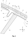
- the angle formed by the support part 153 and the inside surface of the support rib 151 can be made into a right angle, or can be made into an acute angle as shown in FIG. 4 .
- FIG. 4 by using an acute angle for the support part 153, burying inside the leg part 34 is done such that the part supported by the support part 153 of the hinge member 54 becomes a descending slope facing the flange part 33, and the part inside the leg part 34 of the hinge member 54 becomes a gentle ascending slope facing (the position of the lower surface of) the flange part 33.
- the hinge part 35 has the extra length part 52 detour downward between the door part 32 and the leg part 34.
- the support rib 151 may also have an extra length support part 155 that supports the side surface of the leg part 34 side of the extra length part 52.
- the extra length support part 155 is formed as a part of the support part 153 at the door part 32 side of the upper edge part (support part 153) of the support rib 151.
- the extra length support part 155 is a notch of a shape that supports approximately half (half of the side surface and bottom part) of the leg part 34 side of the extra length part 52.
- the support rib 151 is a wide rib that reaches the position of the bottom part of the extra length part 52.
- a mold device for manufacturing 101 of the airbag lid reinforcing member 31 is an item like that shown in FIG. 7 .
- the mold device for manufacturing 101 has a molding space 102 for molding the airbag lid reinforcing member 31 like that shown in FIG. 1 that has the door part 32 that can open and close; the flange part 33 that surrounds the outer periphery of the door part 32; the leg part 34 installed below the flange part 33; and the hinge part 35 that connects the door part 32 to the flange part 33 to be able to open and close.
- the molding space 102 is formed on the inside of upper and lower molds 103, 104 (upper mold, lower mold). In FIG. 2B , FIG. 7 , and FIG.
- a molding space 102a molds the flange part 33
- a molding space 102b molds the leg part 34
- a molding space 102c molds the door part 32.
- the location that clamps the hinge member 54 between the molding space 102a and the molding space 102c is illustrated as a hinge member clamping unit 103a.
- a recess for forming a support rib 156 that molds the support rib 151 is formed having the gap 152 so as to be indented facing the hinge member clamping unit 103a from the molding space 102.
- the recess for forming a support rib 156 may also be an item that forms the support part 153 in the obtuse angle 154. As shown in FIG. 11 (also see FIG. 6 ), the recess for forming a support rib 156 may also be an item that forms the extra length support part 155.
- a hinge member clamping unit 104a that grips the hinge member 54 above and below between itself and the hinge member clamping unit 103a of the mold 103.
- the hinge member clamping unit 103a of the mold 103 and the hinge member clamping unit 104a of the mold 104 are collectively referred to as a clamping unit 110.
- the shape of the hinge member clamping unit 104a of the upper mold 104 forms the upper edge part (support part 153) of the support rib 151, and also, the lower part in the thickness direction of the hinge part 35 (hinge member 54) is buried in the support part 153, and is used to expose the upper part in the thickness direction of the hinge part 35.
- the method for manufacturing the airbag lid reinforcing member 31 manufactures the airbag lid reinforcing member 31 according to any of claims 1-4.
- the airbag lid reinforcing member 31 is manufactured by performing: a step for setting the hinge member 54 on the interior of the opened molds 103, 104 (setting step); a step for doing mold clamping of molds 103, 104 (mold clamping step); an injection molding step for injecting a molten resin 136 ( FIG. 8 ) inside the molding space 102 (from a gate G ( FIG. 2B ); and a mold removal step for doing mold removal of the airbag lid reinforcing member 31 from the molds 103, 104 after the molten resin 136 inside the molding space 102 has hardened to a certain degree.
- the hinge member 54 is set on the lower mold 103.
- the part positioned on the recess for forming a support rib 156 of the hinge member 54 has the upper part supported by the mold 104, while the lower part is exposed in the space of the recess for forming a support rib 156.
- the hinge member 54 is in a fixed state by the clamping unit 110.
- the part that protrudes from the leg part 34 (flange part 33) of the hinge member 54 to the door part 32 side (inside) is also gripped and fixed above and below by the clamping unit 110 of the molds 103, 104 ( FIG. 8 ), so it cannot move.
- the part inside the flange part 33 of the hinge member 54 is in a state for which movement is difficult by restraining as appropriate using the locate-pin 107, etc., in a state set on the lower mold 103.
- the molten resin 136 is injected inside the molding space 102.
- the hinge member 54 positioned on the recess for forming a support rib 156 as noted above is fixed at both sides of the recess for forming a support rib 156 (vehicle width direction Y), so the hinge member 54 creeping into the recess for forming a support rib 156 due to injection pressure is suppressed.
- the support ribs 151 can also have the support part 153 formed at the obtuse angle 154, or have the extra length support part 155 provided.
- the airbag body 4 When the airbag body 4 is deployed and the airbag module 5 comes out during an emergency, the airbag body 4 is guided to follow the leg part 34 while it inflates, and presses the door part 32 and the lid section 21 from below. By this pressing force of the airbag body 4, the cleavage line 23 is cleaved, the door part 32 and the lid section 21 are opened with the hinge part 35 as the center, and the opening 61 is formed in the lid member 6. The airbag body 4 expands to the occupant side inside the passenger compartment 2 from this opening 61, and the upper body of the occupant sitting properly in the seat is protected and restrained.
- the support ribs 151 are provided on the inside surface of the leg part 34. This makes it possible to have the root part 35a on the flange part 33 side of the hinge part 35 protected by the support ribs 151.
- the airbag body 4 is deployed on the interior of the airbag lid reinforcing member 31, and when guided to follow the leg part 34 while inflating, the airbag body 4 directly rubs the root part 35a on the flange part 33 side of the hinge part 35 (the cloth of the airbag body 4 gives shearing force to the hinge part 35), and it is possible to prevent damage to the root part 35a using the support ribs 151.
- a plurality of the support ribs 151 are provided having gaps 152 in the width direction of the leg part 34. By doing this, the contact part of the airbag body 4 on the support ribs 151 is distributed in a plurality of locations, so it is possible to avoid having the support ribs 151 put a burden on the airbag body 4.
- this kind of damage to the root part 35a of the hinge part 35 by the airbag body 4 occurs more easily on the occupant side (rear side) at which the leg part 34 is longer than with the front window side (front side) where the leg part 34 is shorter. This is because when the leg part is short, the airbag body 4 contacts the door part 32 early, so rubbing of the root part 35a and the airbag body 4 does not occur easily, and in contrast to this, when the leg part 34 is long, the airbag body 4 contacting the door part 32 and stopping is relatively late, so rubbing of the root part 35a and the airbag body 4 occurs easily.
- the clamping unit 110 of the molds 103, 104 grips the part of the hinge part 35 between the support ribs 151 and fixes the position. For that reason, there is suppression of for example, the position of the hinge part 35 (hinge member 54) inside the molds 103, 104 being skewed due to the resin pressure (injection pressure) of the molten resin 136, and for example the hinge part 35 being pushed into the inside of the support rib 151 and being completely buried in the support rib 151, and the molten resin 136 entering the top side of the part protruding from the flange part 33 of the hinge part 35 (root part 35a), and the positional relationship between the root part 35a of the hinge part 35 and the support rib 151 is kept in a suitable state, so it is possible for the support ribs 151 to exhibit their original function (function of preventing damage to the hinge part 35, for example).
- the hinge member 54 With the hinge member 54 not being completely exposed at the end surface 33a of the flange part 33, it is possible for a part of the hinge member 54 to be buried inside the support rib 151 at the flange part 33 side. However, even in this case, it is possible to prevent the complete burial of the hinge member 54 inside the support rib 151, so it is possible to ensure exposure from the resin of the upper part of the hinge member 54 in the range facing from the tip 151a of the support rib 151 to the end surface 33a of the flange part 33. Because of that, the root part 35a is positioned further to the outside than the tip 151a of the support rib 151 (see FIG. 4 , FIG. 5 , and FIG. 6 ), and protection of the root part 35a is ensured.
- the support rib 151 may also use the obtuse angle 154 for the support part 153 with respect to the hinge part 35. By doing this, when the airbag body 4 is deployed and passes through the position of the apex of the support rib 151 (corner part of the support rib 151 inside edge part and upper edge part (support part 153)), tearing force input to the airbag body 4 by the apex of the support rib 151 (piercing force on the rib apex by pressure of the airbag body 4 itself) is mitigated, so it is possible to lower the risk of a hole opening in the airbag body 4.
Description
- The present case relates to an airbag lid reinforcing member and the manufacturing method therefor.
- In vehicles such as automobiles, an airbag device is provided as a safety measure for emergencies (e.g. see
Patent Document 1, Patent Document 2). - In this
Patent Document 1, a door part (first backing plate) and a flange part (second backing plate) are connected by a mesh hinge member (easy bending material). With this kind of hinge member, when the airbag is deployed, it is assumed that the boundary part of the hinge member and the flange part (specifically, the root part that protrudes from the flange part in the hinge member) is a fulcrum for rotation. - In
Patent Document 2 as well, a flange part (part indicated by 18 in the document), and a door part (parts indicated bycode numbers code number 36 in the document). Inpatent document FR 3 058 966 A1 -
- [Patent Document 1]
Japanese Laid Open Patent Publication No. 2007-62701 - [Patent Document 2] French Patent Publication No.
FR3015393 Patent Publication FR 3 058 966 A1 - The inventor of the present application discovered that there are the following problems for the inventions of
Patent Document 1 andPatent Document 2 described above. Specifically, with the invention ofPatent Document 1, there is a risk that the cloth of the airbag inflated toward the door during deployment of the airbag will directly touch the boundary part of the hinge member and the flange part. In that case, shearing force is applied to the part that becomes the fulcrum for rotation in the hinge member. - In contrast, with
Patent Document 2, as shown in FIG. 4b of the document, a step part is formed by the end surface of the flange part and the top surface of the leg part, and the hinge member is exposed from the flange part at the top surface of the leg part. If the structure of thisPatent Document 2 is faithfully realized, the fulcrum for rotation of the hinge member is positioned further to the outside than the inner surface of the leg part, and is protected from the cloth of the airbag. - However, with the invention noted in the above-mentioned
Patent Document 2, in the hinge member, there is a risk that a resin layer will be formed on the entire top side of the part exposed from the flange part on the leg part. - Specifically, with the configuration of
Patent Document 2 noted above, when doing insertion molding of the hinge member in the flange part and the leg part, within the mold, the part that becomes the fulcrum for rotation in the hinge member is positioned on the molding space that forms the leg part. However, that molding space does not support the hinge member. For this reason, there is a risk that when injecting resin, the hinge member will bend due to injection pressure, the leg part will be molded in a state with the hinge member entered into the molding space, and the hinge member will end up creeping into the leg part. As a result, in the hinge member, the location that is exposed from the resin and becomes the fulcrum for rotation ends up moving to the inner surface side of the leg part. When that happens, ultimately this is the same as with the configuration ofCited Document 1, with the cloth of the airbag directly touching the fulcrum for rotation, and the problem relating to shearing stress on the hinge member accompanying deployment of the airbag occurring. - In light of this, the main purpose of the present case is to address the problems noted above.
- To address the problems noted above, the present case is an airbag lid reinforcing member as defined by
claim 1. -
-
FIG. 1 is a vertical cross section diagram of an airbag device of the present embodiment. -
FIG. 2 is a cross section diagram viewing a leg part from the position of line II-II ofFIG. 1 . -
FIG. 2A is a partial plan view of an airbag lid reinforcing member ofFIG. 1 . -
FIG. 2B is a partial plan view of the lower mold of a mold device for manufacturing. -
FIG. 3 is an enlarged view of a part without support ribs inFIG. 1 , and a cross section diagram of line A-A inFIG. 2A . -
FIG. 4 is an enlarged view of a part having support ribs inFIG. 1 , and is a cross section diagram of line B-B inFIG. 2A . -
FIG. 5 is a partial enlarged view of a modification example ofFIG. 4 . -
FIG. 6 is a partial enlarged view of another modification example ofFIG 4 . -
FIG. 7 is a vertical cross section diagram of a mold device for manufacturing the airbag lid reinforcing member. -
FIG. 8 is a cross section diagram along line C-C inFIG. 2B corresponding to the upper peripheral part (part without support ribs) of the leg part of the mold device for manufacturing inFIG. 7 . -
FIG. 9 is a cross section diagram along line D-D inFIG. 2B corresponding to the upper peripheral part (part with support ribs) of the leg part of the mold device for manufacturing inFIG. 7 . -
FIG. 10 is a partial enlarged view of the same kind of mold device for manufacturing as inFIG. 8 for a modification example inFIG. 4 . -
FIG. 11 is a partial enlarged view of the same kind of mold device for manufacturing as inFIG. 8 for another modification example inFIG. 5 . - Hereafter, the present embodiment is explained in detail using the drawings.
-
FIG. 1 to FIG. 11 are for explaining this embodiment. - Hereafter, the configuration of this embodiment is explained.
-
FIG. 1 shows an airbag device. The directions in the drawing are vehicle front-rear direction X, vehicle width direction Y, and vertical direction Z. - In a
vehicle 1 such as an automobile, anairbag device 3 is provided inside apassenger compartment 2 as a safety measure for emergencies. For example, theairbag device 3 for the passenger seat comprises anairbag module 5 that houses a folded bag-shaped airbag body 4, alid member 6, and an airbaglid reinforcing member 31. - During deployment, the
airbag body 4 expands from an opening part formed on the top surface side of theairbag module 5 diagonally upward and backward facing the occupant side. InFIG. 1 , the expansion direction of theairbag body 4 is noted ascode number 41. In this way, to expand theairbag body 4, theairbag module 5 is placed tilted with respect to the surface of thelid member 6 facing in approximately the vertical direction Z in a state with the opening part of the top surface of theairbag module 5 facing the occupant side. - The
lid member 6 conceals theairbag module 5 from above at normal times, and also forms anopening 61 by which theairbag body 4 deployed from theairbag module 5 is expanded toward inside thepassenger compartment 2 during an emergency. Thelid member 6 has alid section 21 that is opened by theairbag body 4, and a lidouter periphery part 22 that surrounds the outer periphery of thelid section 21. - With this embodiment, two
lid sections 21 are provided in a vehicle front-rear direction X (first lid section (vehicle front side) and second lid section (vehicle rear side)). Thelid section 21 and the lidouter periphery part 22 are defined by acleavage line 23. Thecleavage line 23 is a notch formed on the rear surface side of thelid member 6, at a depth that does not reach the surface of thelid member 6. Thelid member 6 includes items that are integrated with aninstrument panel 8, and items that are separate from theinstrument panel 8. Generally, theinstrument panel 8 has a top surface part positioned under a front window and facing approximately the vertical direction Z, and a front side surface part that extends approximately downward from the edge part of the occupant side of the top surface part, and thelid member 6 is provided at the position of the top surface part. - The airbag
lid reinforcing member 31 is attached to the rear surface side of thelid member 6 to reinforce thelid member 6, houses at least a portion of theairbag module 5, and guides theairbag body 4 deployed from theairbag module 5 to thelid member 6. - The airbag
lid reinforcing member 31 has adoor part 32, aflange part 33, aleg part 34, and ahinge part 35. Among these, twodoor parts 32 are provided in the vehicle front-rear direction X (first door part (vehicle front side) and second door part (vehicle rear side)), these are attached to the rear surface of eachlid section 21 to reinforce eachlid section 21, and integrated with thelid section 21 to be able to open and close. - The
flange part 33 surrounds the outer periphery of thedoor part 32 with a gap in the circumferential direction, and is attached to the rear surface of the lidouter periphery part 22 to reinforce the lidouter periphery part 22. Weldingribs lid member 6 are provided on the front surface of thedoor part 32 and theflange part 33. - The
leg part 34 is installed below thedoor part 32 and theflange part 33 in a state surrounding the upper part of theairbag module 5. In theleg part 34, the upper part of theairbag module 5 is made to be inserted from below, and theleg part 34 functions as a guide part for guiding the deployedairbag body 4 toward thedoor part 32 and thelid section 21. For that reason, theleg part 34 is in an approximate frame shape surrounding the position of the outside of thedoor part 32 or the outer periphery side of thedoor part 32 and extending in the expansion direction 41 (seeFIG. 1 ) to inside thepassenger compartment 2. - With the present embodiment, as described above, the configuration is such that the
airbag module 5 is placed tilted in a state facing the occupant side, and in theopening 61 of thelid member 6, theexpansion direction 41 of theairbag body 4 is tilted (at least it is not orthogonal) with respect to the virtual straight line connecting the end part of the vehicle front side and the end part of the vehicle rear side. As a result, when theleg part 34 is seen from the side, the occupant side (rear side) is longer than the front window side (front side). Specifically, the distance from theairbag module 5 to the occupant side hingepart 35 is longer than the distance from theairbag module 5 to the front window side (front side) hingepart 35. - Also, a
hook part 42 is provided on the front and back side surfaces of the upper part of theairbag module 5, and alocking hole 43 that can be loosely fitted with thehook part 42 is formed on theleg part 34. Attachment between the upper part of theairbag module 5 and theleg part 34 is not limited to thehook part 42, and can be done by fixing with a bolt, etc., for example. Also, the lower part of theairbag module 5 is fixed usingbrackets body strength member 44 such as a steering support member provided in the vehicle body. - The
hinge part 35 connects thedoor part 32 to theflange part 33 to be able to open and close. With this embodiment, thehinge part 35 has a vehicle front hinge part that connects the first door part and theflange part 33, and a vehicle rear hinge part that connects the second door part and theflange part 33. Thehinge part 35 has anextra length part 52 that becomes the rotation center of thedoor part 32. Theextra length part 52 is placed at a position between thedoor part 32 and theleg part 34 so as to detour downward. Theextra length part 52 is approximately a U shape or approximately a V shape in the side view. Thehinge part 35 is configured by ahinge member 54 that is formed by a separate member. For thehinge member 54, it is possible to use a flexible net or film made of resin, or mesh made of metal, etc. With this embodiment, a net made of resin is used for thehinge member 54. With thehinge member 54, using insert molding, in a state with theextra length part 52 or its peripheral part exposed in the gap between thedoor part 32 and theleg part 34 and theflange part 33, both side parts of theextra length part 52 are buried in the interior of thedoor part 32 and theflange part 33 or theleg part 34. - For the basic configuration as noted above, with this embodiment, the following kind of configuration is used.
- The airbag
lid reinforcing member 31 of this embodiment has: thedoor part 32 that can open and close; theflange part 33 that surrounds the outer periphery of thedoor part 32; theleg part 34 installed below theflange part 33; and thehinge part 35 that connects thedoor part 32 to theflange part 33 to be able to open and close. - Here, the
hinge part 35 is constituted by aseparate hinge member 54. In thehinge member 54, the boundary part with the flange part 33 (or the leg part 34) at theopening 61 side is called aroot part 35a. Thisroot part 35a is the fulcrum for rotation of thehinge member 54 when thedoor part 32 opens. - (1) As shown in
FIG. 2 ,support ribs 151 are provided on the inside surface of theleg part 34 to support thehinge part 35 from the lower surface side (see cross section of the part without ribs inFIG. 2A ,FIG. 2B , andFIG. 3 , and the part with ribs inFIG. 4 ). InFIG. 2 , the illustration omits thehook part 42 of theairbag module 5. - A plurality of the
support ribs 151 are provided in the width direction of the leg part 34 (vehicle width direction Y) havinggaps 152. - Here, the
support ribs 151 are inner ribs along the inside surface of theleg part 34. InFIG. 4 , thesupport ribs 151 receive theleg part 34 side part more than theextra length part 52 in thehinge member 54. For that reason, they are narrow ribs that do not reach theextra length part 52. - There is a risk that if the number of
support ribs 151 is small, there may be a burden on theairbag body 4, so a larger number of thesupport ribs 151 are provided to a level at which there will not be a burden on theairbag body 4. Also, when thegaps 152 between thesupport ribs 151 are too large, theairbag body 4 enters between thosesupport ribs 151, and contacts theroot part 35a that is the fulcrum for rotation of thehinge member 54, so the number is set as appropriate from this perspective as well. On the other hand, the mold may enter the space between thesupport ribs 151 during molding, so the minimum required dimensions of thegaps 152 depends on the strength of the mold. InFIG. 2 , thesupport ribs 151 are provided in a number of approximately 3 times or greater than that of the locking holes 43 provided in theleg part 34. However, the number ofsupport ribs 151 and thegaps 152 are not limited to what is noted above. - Hereafter, the upper edge part of the
support ribs 151 is called asupport part 153. The lower part in the thickness direction of the hinge part 35 (hinge member 54) is buried in thesupport part 153. The upper part in the thickness direction of thehinge part 35 is exposed, without being buried in thesupport part 153. Also, during deployment of theairbag body 4, by opening of thelid section 21, the lower part in the thickness direction of the hinge part 35 (hinge member 54) is peeled from thesupport part 153, and the boundary part with anend surface 33a of the flange part 33 (or the inner surface of the leg part 34) in thehinge member 54 becomes the fulcrum for rotation, and thedoor part 32 opens. At this time, thehinge part 35 is deformed according to the opening of thelid section 21, and thesupport ribs 151 remain in place without deforming. - (2) As shown in the modification example of
FIG. 5 , thesupport part 153 may also be anobtuse angle 154. - The
obtuse angle 154 is an angle formed by the inside surface and the upper edge part (support part 153) of thesupport rib 151. InFIG. 5 , by using theobtuse angle 154 for thesupport part 153, burying inside theleg part 34 is done such that the part supported by thesupport part 153 of thehinge member 54 becomes an ascending slope facing theflange part 33, and the part inside theleg part 34 of thehinge member 54 becomes a gentle descending slope facing (the position of the lower surface of) theflange part 33. - The angle formed by the
support part 153 and the inside surface of thesupport rib 151 can be made into a right angle, or can be made into an acute angle as shown inFIG. 4 . InFIG. 4 , by using an acute angle for thesupport part 153, burying inside theleg part 34 is done such that the part supported by thesupport part 153 of thehinge member 54 becomes a descending slope facing theflange part 33, and the part inside theleg part 34 of thehinge member 54 becomes a gentle ascending slope facing (the position of the lower surface of) theflange part 33. - (3) As shown in another modification example in
FIG. 6 , thehinge part 35 has theextra length part 52 detour downward between thedoor part 32 and theleg part 34. Thesupport rib 151 may also have an extralength support part 155 that supports the side surface of theleg part 34 side of theextra length part 52. - Here, the extra
length support part 155 is formed as a part of thesupport part 153 at thedoor part 32 side of the upper edge part (support part 153) of thesupport rib 151. The extralength support part 155 is a notch of a shape that supports approximately half (half of the side surface and bottom part) of theleg part 34 side of theextra length part 52. For that reason, thesupport rib 151 is a wide rib that reaches the position of the bottom part of theextra length part 52. - A mold device for manufacturing 101 of the airbag
lid reinforcing member 31 is an item like that shown inFIG. 7 . The mold device for manufacturing 101 has amolding space 102 for molding the airbaglid reinforcing member 31 like that shown inFIG. 1 that has thedoor part 32 that can open and close; theflange part 33 that surrounds the outer periphery of thedoor part 32; theleg part 34 installed below theflange part 33; and thehinge part 35 that connects thedoor part 32 to theflange part 33 to be able to open and close. Themolding space 102 is formed on the inside of upper andlower molds 103, 104 (upper mold, lower mold). InFIG. 2B ,FIG. 7 , andFIG. 8 , amolding space 102a molds theflange part 33, amolding space 102b molds theleg part 34, and amolding space 102c molds thedoor part 32. Also, in themold 103, the location that clamps thehinge member 54 between themolding space 102a and themolding space 102c is illustrated as a hingemember clamping unit 103a. - Also, as shown in
FIG. 9 (also seeFIG. 2B ), a recess for forming asupport rib 156 that molds thesupport rib 151 is formed having thegap 152 so as to be indented facing the hingemember clamping unit 103a from themolding space 102. - As shown in
FIG. 10 (also seeFIG. 5 ), the recess for forming asupport rib 156 may also be an item that forms thesupport part 153 in theobtuse angle 154. As shown inFIG. 11 (also seeFIG. 6 ), the recess for forming asupport rib 156 may also be an item that forms the extralength support part 155. - In addition to the above, provided in the
molds extra length part 105 for forming theextra length part 52 of thehinge part 35, and a recess for forming an extra length part 109 (extra length forming part). Also, on the inside of themolds pin 107 that is inserted in a locate-hole 108 provided on thehinge member 54 for positioning thehinge member 54 is provided as appropriate. - Also, as shown in
FIG. 8 , formed in themold 104 is a hingemember clamping unit 104a that grips thehinge member 54 above and below between itself and the hingemember clamping unit 103a of themold 103. The hingemember clamping unit 103a of themold 103 and the hingemember clamping unit 104a of themold 104 are collectively referred to as aclamping unit 110. By being formed connected also to the top side of the recess for forming asupport rib 156, the shape of the hingemember clamping unit 104a of theupper mold 104 forms the upper edge part (support part 153) of thesupport rib 151, and also, the lower part in the thickness direction of the hinge part 35 (hinge member 54) is buried in thesupport part 153, and is used to expose the upper part in the thickness direction of thehinge part 35. - The method for manufacturing the airbag
lid reinforcing member 31 manufactures the airbaglid reinforcing member 31 according to any of claims 1-4. - Here, the airbag
lid reinforcing member 31 is manufactured by performing: a step for setting thehinge member 54 on the interior of the openedmolds 103, 104 (setting step); a step for doing mold clamping ofmolds 103, 104 (mold clamping step); an injection molding step for injecting a molten resin 136 (FIG. 8 ) inside the molding space 102 (from a gate G (FIG. 2B ); and a mold removal step for doing mold removal of the airbaglid reinforcing member 31 from themolds molten resin 136 inside themolding space 102 has hardened to a certain degree. - During the setting step, the
hinge member 54 is set on thelower mold 103. - At this time, the part positioned on the recess for forming a
support rib 156 of thehinge member 54 has the upper part supported by themold 104, while the lower part is exposed in the space of the recess for forming asupport rib 156. However, at both sides of this recess for forming a support rib 156 (vehicle width direction Y), thehinge member 54 is in a fixed state by theclamping unit 110. Similarly, the part that protrudes from the leg part 34 (flange part 33) of thehinge member 54 to thedoor part 32 side (inside) is also gripped and fixed above and below by theclamping unit 110 of themolds 103, 104 (FIG. 8 ), so it cannot move. - Also, the part inside the
flange part 33 of thehinge member 54 is in a state for which movement is difficult by restraining as appropriate using the locate-pin 107, etc., in a state set on thelower mold 103. - With the injection molding step, the
molten resin 136 is injected inside themolding space 102. This makes it possible to obtain the airbaglid reinforcing member 31 having thesupport ribs 151. At this time, thehinge member 54 positioned on the recess for forming asupport rib 156 as noted above is fixed at both sides of the recess for forming a support rib 156 (vehicle width direction Y), so thehinge member 54 creeping into the recess for forming asupport rib 156 due to injection pressure is suppressed. Thesupport ribs 151 can also have thesupport part 153 formed at theobtuse angle 154, or have the extralength support part 155 provided. - Following, the action of this embodiment is explained.
- When the
airbag body 4 is deployed and theairbag module 5 comes out during an emergency, theairbag body 4 is guided to follow theleg part 34 while it inflates, and presses thedoor part 32 and thelid section 21 from below. By this pressing force of theairbag body 4, thecleavage line 23 is cleaved, thedoor part 32 and thelid section 21 are opened with thehinge part 35 as the center, and theopening 61 is formed in thelid member 6. Theairbag body 4 expands to the occupant side inside thepassenger compartment 2 from thisopening 61, and the upper body of the occupant sitting properly in the seat is protected and restrained. - With this embodiment, the following kinds of effects can be obtained.
- (Effect 1) The
support ribs 151 are provided on the inside surface of theleg part 34. This makes it possible to have theroot part 35a on theflange part 33 side of thehinge part 35 protected by thesupport ribs 151. - For that reason, the
airbag body 4 is deployed on the interior of the airbaglid reinforcing member 31, and when guided to follow theleg part 34 while inflating, theairbag body 4 directly rubs theroot part 35a on theflange part 33 side of the hinge part 35 (the cloth of theairbag body 4 gives shearing force to the hinge part 35), and it is possible to prevent damage to theroot part 35a using thesupport ribs 151. - Also, a plurality of the
support ribs 151 are provided havinggaps 152 in the width direction of theleg part 34. By doing this, the contact part of theairbag body 4 on thesupport ribs 151 is distributed in a plurality of locations, so it is possible to avoid having thesupport ribs 151 put a burden on theairbag body 4. - In a case when there are no
support ribs 151 in the present embodiment, this kind of damage to theroot part 35a of thehinge part 35 by theairbag body 4 occurs more easily on the occupant side (rear side) at which theleg part 34 is longer than with the front window side (front side) where theleg part 34 is shorter. This is because when the leg part is short, theairbag body 4 contacts thedoor part 32 early, so rubbing of theroot part 35a and theairbag body 4 does not occur easily, and in contrast to this, when theleg part 34 is long, theairbag body 4 contacting thedoor part 32 and stopping is relatively late, so rubbing of theroot part 35a and theairbag body 4 occurs easily. - Also, at the positions between support ribs 151 (parts without ribs), during molding, the
clamping unit 110 of themolds hinge part 35 between thesupport ribs 151 and fixes the position. For that reason, there is suppression of for example, the position of the hinge part 35 (hinge member 54) inside themolds molten resin 136, and for example thehinge part 35 being pushed into the inside of thesupport rib 151 and being completely buried in thesupport rib 151, and themolten resin 136 entering the top side of the part protruding from theflange part 33 of the hinge part 35 (root part 35a), and the positional relationship between theroot part 35a of thehinge part 35 and thesupport rib 151 is kept in a suitable state, so it is possible for thesupport ribs 151 to exhibit their original function (function of preventing damage to thehinge part 35, for example). - Actually, with the
hinge member 54 not being completely exposed at theend surface 33a of theflange part 33, it is possible for a part of thehinge member 54 to be buried inside thesupport rib 151 at theflange part 33 side. However, even in this case, it is possible to prevent the complete burial of thehinge member 54 inside thesupport rib 151, so it is possible to ensure exposure from the resin of the upper part of thehinge member 54 in the range facing from thetip 151a of thesupport rib 151 to theend surface 33a of theflange part 33. Because of that, theroot part 35a is positioned further to the outside than thetip 151a of the support rib 151 (seeFIG. 4 ,FIG. 5 , andFIG. 6 ), and protection of theroot part 35a is ensured. - (Effect 2) The
support rib 151 may also use theobtuse angle 154 for thesupport part 153 with respect to thehinge part 35. By doing this, when theairbag body 4 is deployed and passes through the position of the apex of the support rib 151 (corner part of thesupport rib 151 inside edge part and upper edge part (support part 153)), tearing force input to theairbag body 4 by the apex of the support rib 151 (piercing force on the rib apex by pressure of theairbag body 4 itself) is mitigated, so it is possible to lower the risk of a hole opening in theairbag body 4. - (Effect 3) It is also possible to provide the extra
length support part 155 on thesupport rib 151. This makes it possible to directly support and fix the side surface of theleg part 34 of theextra length part 52 in a wide range. This makes it possible to always keep theextra length part 52 in a stable state. - (Effect 4) With the mold device for manufacturing 101 of the airbag
lid reinforcing member 31, it is possible to obtain the same action and effects as noted above. - (Effect 5) With the manufacturing method of the airbag
lid reinforcing member 31, it is possible to obtain the same action and effects as noted above. At this time, a plurality of thesupport ribs 151 havinggaps 152 in the width direction of theleg part 34 are placed at the inside surface of theleg part 34, and by doing molding to place theroot part 35a of thehinge part 35 at the position of the apex of thesupport rib 151, thehinge part 35 is fixed by being gripped from above and below by theclamping unit 110 of themolds support ribs 151, so creeping of thehinge part 35 to the inside of thesupport rib 151 at the position of the support rib 151 (both sides are fixed by gripping by theclamping unit 110 of themolds 103, 104) is suppressed. -
- 4
- Airbag body
- 23
- Cleavage line
- 31
- Airbag lid reinforcing member
- 32
- Door part
- 33
- Flange part
- 34
- Leg part
- 35
- Hinge part
- 52
- Extra length part
- 54
- Hinge member (net)
- 101
- Mold device for manufacturing
- 103
- Mold (lower mold)
- 104
- Mold (upper mold)
- 110
- Clamping unit
- 151
- Support rib
- 152
- Gap
- 153
- Support part
- 154
- Obtuse angle
- 155
- Extra length support part
- 156
- Recess for forming support rib (recess)
- X
- Vehicle front-rear direction
- Y
- Vehicle width direction
- Z
- Vertical direction
Claims (5)
- An airbag lid reinforcing member (31) comprising:a door part (32) that can open and close;a flange part (33) made of resin that surrounds an outer periphery of the door part (33);a leg part (34) made of resin installed on a lower side of the flange part (33); anda hinge part (35) that is constituted by a hinge member (54), separate from the flange part (33), and that connects the flange part (33) and the door part (32) to be able to open and close, whereinon an inside surface of the leg part (34), a plurality of support ribs (151) that support the hinge member (54) from a lower surface side are provided having a gap (152) in a width direction of the leg part (34),a portion of the hinge member (54) is buried in the flange part (33),in a portion of the hinge member on the support rib (151), in a range from a tip of the support rib (151) to an end surface (33a) of the flange part (33), at least an upper part in a thickness direction of the hinge member (54) is exposed from the support rib (151), and a lower part in a thickness direction of the hinge member (54) is buried in a support part (153) of the support rib (151), the support part (153) being an upper edge part of the support rib (151), wherebyduring deployment of an airbag body (4), the lower part in the thickness direction of the hinge member (54) is peeled from the support part (153) of the support rib (151), and the boundary part with an end surface of the flange part (33) in the hinge member (54) becomes the fulcrum for rotation, anda portion of the hinge member (54) positioned between the support ribs (151) is exposed from the support ribs (151) and the flange part (33).
- The airbag lid reinforcing member according to claim 1, wherein
the hinge member (54) is a net. - The airbag lid reinforcing member according to claim 1, whereinthe door part (32) has a first door part placed at a vehicle front side with respect to a cleavage line (23), and a second door part placed at a vehicle rear side with respect to the cleavage line (23),the hinge member (54) having:a vehicle front hinge part that connects the first door part and the flange part (33), anda vehicle rear hinge part that connects the second door part and the flange part (33),an airbag body (4) is attached to the leg part (34), anda distance from a center position of a vehicle front-rear direction (X) of the airbag body (4) to the vehicle rear hinge part is longer than a distance from the center position to the vehicle front hinge part.
- The airbag lid reinforcing member according to claim 1, wherein
in the support ribs (151), an angle (154) that an upper edge part in contact with the hinge member (54) forms with respect to an inside surface of the support rib (151) is an obtuse angle (154). - A method for manufacturing an airbag lid reinforcing member according to any one of the preceding claims, in which the hinge member (54) is formed in the flange part (33) and the door part (32) by insert molding using a mold (101) for which a molding space (102) is formed corresponding to the door part (32) that can open and close, the flange part (33) that surrounds an outer periphery of the door part (32), and the leg part (34) installed below the flange part (33), wherein
the mold (101) has:an upper mold (103) positioned for molding a top surface side of the door part (32) and the flange part (33), anda lower mold (104) for molding a lower surface side of the door part (32) and the flange part (33), and also the leg part (34),on the lower mold (104), there is a plurality of recesses indented in a direction separating from the flange part (33) on a part for molding an inside surface of the leg part (34), andin the insert molding, injection molding is done in a state with the hinge member (54) gripped by a part between adjacent recesses of the lower mold (104), and the upper mold (103).
Applications Claiming Priority (2)
| Application Number | Priority Date | Filing Date | Title |
|---|---|---|---|
| JP2018118008A JP6563082B1 (en) | 2018-06-21 | 2018-06-21 | Airbag grid reinforcing member and manufacturing method thereof |
| PCT/JP2019/024416 WO2019244963A1 (en) | 2018-06-21 | 2019-06-20 | Air bag lid reinforcing member and method for manufacturing same |
Publications (3)
| Publication Number | Publication Date |
|---|---|
| EP3812220A4 EP3812220A4 (en) | 2021-04-28 |
| EP3812220A1 EP3812220A1 (en) | 2021-04-28 |
| EP3812220B1 true EP3812220B1 (en) | 2022-03-09 |
Family
ID=67692135
Family Applications (1)
| Application Number | Title | Priority Date | Filing Date |
|---|---|---|---|
| EP19822646.6A Active EP3812220B1 (en) | 2018-06-21 | 2019-06-20 | Air bag lid reinforcing member and method for manufacturing same |
Country Status (5)
| Country | Link |
|---|---|
| US (1) | US11390237B2 (en) |
| EP (1) | EP3812220B1 (en) |
| JP (1) | JP6563082B1 (en) |
| CN (1) | CN112313120B (en) |
| WO (1) | WO2019244963A1 (en) |
Families Citing this family (1)
| Publication number | Priority date | Publication date | Assignee | Title |
|---|---|---|---|---|
| KR102638696B1 (en) * | 2018-09-06 | 2024-02-21 | 현대모비스 주식회사 | Chute of passenger air bag |
Family Cites Families (21)
| Publication number | Priority date | Publication date | Assignee | Title |
|---|---|---|---|---|
| DE4120852A1 (en) * | 1991-06-25 | 1993-01-07 | Kolbenschmidt Ag | IMPACT PROTECTION DEVICE |
| JP2002087197A (en) * | 2000-09-19 | 2002-03-26 | Daihatsu Motor Co Ltd | Cover structure of air bag system |
| EP1410958B1 (en) | 2002-10-15 | 2006-08-02 | Nishikawa Kasei Co., Ltd. | Vehicle air bag door |
| JP4198488B2 (en) * | 2003-02-24 | 2008-12-17 | ダイキョーニシカワ株式会社 | Airbag door for vehicle |
| JP2007062701A (en) | 2005-09-02 | 2007-03-15 | Takata Corp | Air bag device and its cover member |
| JP5116252B2 (en) | 2006-04-20 | 2013-01-09 | 日本プラスト株式会社 | Cover body of airbag device |
| DE102007055016B3 (en) * | 2007-11-14 | 2008-11-27 | Faurecia Innenraum Systeme Gmbh | Covering piece for passenger air bag, has folding airbag cover, in which airbag cover is articulated by flexible laminar support element, which is fastened with end of airbag cover and with another end at fastening outside airbag cover |
| US8181987B2 (en) * | 2010-06-27 | 2012-05-22 | Ford Global Technologies, Llc | Air bag deployment door with force transmitting hinge |
| KR101240603B1 (en) * | 2010-11-22 | 2013-03-06 | 현대모비스 주식회사 | Passenger air bag door |
| CN201907477U (en) * | 2010-12-31 | 2011-07-27 | 常州新泉汽车内饰件有限公司 | Passenger air bag support frame |
| JP5725170B2 (en) * | 2011-05-24 | 2015-05-27 | トヨタ自動車株式会社 | Instrument panel with integrated airbag door |
| FR2979600B1 (en) | 2011-09-01 | 2013-09-27 | Faurecia Interieur Ind | SAFETY DEVICE FOR VEHICLE |
| FR3007350B1 (en) * | 2013-06-24 | 2015-06-05 | Faurecia Interieur Ind | SAFETY DEVICE FOR VEHICLE. |
| FR3007347B1 (en) | 2013-06-24 | 2017-02-24 | Faurecia Interieur Ind | METHOD FOR INJECTION MOLDING AN INFLATABLE SAFETY CUSHION CASE. |
| DE102013214147A1 (en) | 2013-07-18 | 2015-01-22 | Volkswagen Aktiengesellschaft | Airbag arrangement for a vehicle |
| FR3015393B1 (en) | 2013-12-19 | 2016-01-22 | Faurecia Interieur Ind | SAFETY DEVICE FOR VEHICLE |
| EP3034361B1 (en) * | 2014-12-16 | 2018-04-18 | Volvo Car Corporation | Airbag cover and manufacturing method for airbag cover |
| JP2018024267A (en) * | 2016-08-08 | 2018-02-15 | カルソニックカンセイ株式会社 | Airbag lid reinforcing member and its manufacturing method |
| JP2018024296A (en) * | 2016-08-09 | 2018-02-15 | カルソニックカンセイ株式会社 | Airbag lid reinforcing member and its manufacturing method |
| FR3058966B1 (en) * | 2016-11-24 | 2020-11-13 | Faurecia Interieur Ind | VEHICLE SAFETY DEVICE |
| KR102378052B1 (en) * | 2017-10-31 | 2022-03-24 | 현대모비스 주식회사 | Passenger air bag door for vehicle |
-
2018
- 2018-06-21 JP JP2018118008A patent/JP6563082B1/en active Active
-
2019
- 2019-06-20 EP EP19822646.6A patent/EP3812220B1/en active Active
- 2019-06-20 CN CN201980040532.9A patent/CN112313120B/en active Active
- 2019-06-20 US US17/253,713 patent/US11390237B2/en active Active
- 2019-06-20 WO PCT/JP2019/024416 patent/WO2019244963A1/en active Application Filing
Also Published As
| Publication number | Publication date |
|---|---|
| EP3812220A4 (en) | 2021-04-28 |
| WO2019244963A1 (en) | 2019-12-26 |
| EP3812220A1 (en) | 2021-04-28 |
| CN112313120B (en) | 2023-01-31 |
| JP6563082B1 (en) | 2019-08-21 |
| US11390237B2 (en) | 2022-07-19 |
| JP2019217958A (en) | 2019-12-26 |
| CN112313120A (en) | 2021-02-02 |
| US20210261082A1 (en) | 2021-08-26 |
Similar Documents
| Publication | Publication Date | Title |
|---|---|---|
| JP5414052B2 (en) | Airbag clip | |
| US7232151B2 (en) | Airbag device | |
| JPH03279055A (en) | Automotive air bag device | |
| JP3784130B2 (en) | Airbag device for vehicle | |
| EP3812220B1 (en) | Air bag lid reinforcing member and method for manufacturing same | |
| JP5116252B2 (en) | Cover body of airbag device | |
| JP6482280B2 (en) | Airbag mounting structure and airbag mounting method | |
| JP2014051251A (en) | Air bag device | |
| JP6035960B2 (en) | Pillar garnish | |
| EP1745988A1 (en) | Airbag apparatus | |
| JP4379287B2 (en) | Cover body of airbag device | |
| WO2013094338A1 (en) | Airbag device and module cover thereof | |
| KR20230015719A (en) | Tether clip and pillar structure provided with the same | |
| JP5222631B2 (en) | Airbag cover and airbag device | |
| JP6551367B2 (en) | Airbag device | |
| JP5981366B2 (en) | Vibration weld structure | |
| JP2000177525A (en) | Structure of air bag door and manufacturing of the same | |
| JP7218079B1 (en) | Airbag mounting structure | |
| KR100698683B1 (en) | Mounting Structure of Air-bag housing and door | |
| JP2019217962A (en) | Air bag grid reinforcement member, mold assembly for manufacturing the same, and manufacturing method | |
| KR20170124856A (en) | Holding member of curtain airbag and curtain air bag device | |
| JP6752119B2 (en) | Airbag device | |
| JP2019217963A (en) | Air bag grid reinforcement member, mold assembly for manufacturing the same, and manufacturing method | |
| JP3903248B2 (en) | Fixing structure of door reinforcement member | |
| JP4029277B2 (en) | Door support member mounting structure |
Legal Events
| Date | Code | Title | Description |
|---|---|---|---|
| STAA | Information on the status of an ep patent application or granted ep patent |
Free format text: STATUS: THE INTERNATIONAL PUBLICATION HAS BEEN MADE |
|
| STAA | Information on the status of an ep patent application or granted ep patent |
Free format text: STATUS: THE INTERNATIONAL PUBLICATION HAS BEEN MADE |
|
| PUAI | Public reference made under article 153(3) epc to a published international application that has entered the european phase |
Free format text: ORIGINAL CODE: 0009012 |
|
| STAA | Information on the status of an ep patent application or granted ep patent |
Free format text: STATUS: REQUEST FOR EXAMINATION WAS MADE |
|
| 17P | Request for examination filed |
Effective date: 20201217 |
|
| A4 | Supplementary search report drawn up and despatched |
Effective date: 20210208 |
|
| AK | Designated contracting states |
Kind code of ref document: A1 Designated state(s): AL AT BE BG CH CY CZ DE DK EE ES FI FR GB GR HR HU IE IS IT LI LT LU LV MC MK MT NL NO PL PT RO RS SE SI SK SM TR |
|
| AX | Request for extension of the european patent |
Extension state: BA ME |
|
| REG | Reference to a national code |
Ref country code: DE Ref legal event code: R079 Ref document number: 602019012461 Country of ref document: DE Free format text: PREVIOUS MAIN CLASS: B60R0021205000 Ipc: B29L0031300000 |
|
| DAV | Request for validation of the european patent (deleted) | ||
| DAX | Request for extension of the european patent (deleted) | ||
| GRAP | Despatch of communication of intention to grant a patent |
Free format text: ORIGINAL CODE: EPIDOSNIGR1 |
|
| STAA | Information on the status of an ep patent application or granted ep patent |
Free format text: STATUS: GRANT OF PATENT IS INTENDED |
|
| RIC1 | Information provided on ipc code assigned before grant |
Ipc: B60R 21/215 20110101ALI20210914BHEP Ipc: B29C 45/00 20060101ALI20210914BHEP Ipc: B29C 45/14 20060101ALI20210914BHEP Ipc: B60R 21/205 20110101ALI20210914BHEP Ipc: B29L 31/30 20060101AFI20210914BHEP |
|
| INTG | Intention to grant announced |
Effective date: 20211001 |
|
| GRAS | Grant fee paid |
Free format text: ORIGINAL CODE: EPIDOSNIGR3 |
|
| GRAA | (expected) grant |
Free format text: ORIGINAL CODE: 0009210 |
|
| STAA | Information on the status of an ep patent application or granted ep patent |
Free format text: STATUS: THE PATENT HAS BEEN GRANTED |
|
| AK | Designated contracting states |
Kind code of ref document: B1 Designated state(s): AL AT BE BG CH CY CZ DE DK EE ES FI FR GB GR HR HU IE IS IT LI LT LU LV MC MK MT NL NO PL PT RO RS SE SI SK SM TR |
|
| REG | Reference to a national code |
Ref country code: CH Ref legal event code: EP Ref country code: AT Ref legal event code: REF Ref document number: 1473776 Country of ref document: AT Kind code of ref document: T Effective date: 20220315 |
|
| REG | Reference to a national code |
Ref country code: IE Ref legal event code: FG4D |
|
| REG | Reference to a national code |
Ref country code: DE Ref legal event code: R096 Ref document number: 602019012461 Country of ref document: DE |
|
| REG | Reference to a national code |
Ref country code: LT Ref legal event code: MG9D |
|
| REG | Reference to a national code |
Ref country code: NL Ref legal event code: MP Effective date: 20220309 |
|
| PG25 | Lapsed in a contracting state [announced via postgrant information from national office to epo] |
Ref country code: SE Free format text: LAPSE BECAUSE OF FAILURE TO SUBMIT A TRANSLATION OF THE DESCRIPTION OR TO PAY THE FEE WITHIN THE PRESCRIBED TIME-LIMIT Effective date: 20220309 Ref country code: RS Free format text: LAPSE BECAUSE OF FAILURE TO SUBMIT A TRANSLATION OF THE DESCRIPTION OR TO PAY THE FEE WITHIN THE PRESCRIBED TIME-LIMIT Effective date: 20220309 Ref country code: NO Free format text: LAPSE BECAUSE OF FAILURE TO SUBMIT A TRANSLATION OF THE DESCRIPTION OR TO PAY THE FEE WITHIN THE PRESCRIBED TIME-LIMIT Effective date: 20220609 Ref country code: LT Free format text: LAPSE BECAUSE OF FAILURE TO SUBMIT A TRANSLATION OF THE DESCRIPTION OR TO PAY THE FEE WITHIN THE PRESCRIBED TIME-LIMIT Effective date: 20220309 Ref country code: HR Free format text: LAPSE BECAUSE OF FAILURE TO SUBMIT A TRANSLATION OF THE DESCRIPTION OR TO PAY THE FEE WITHIN THE PRESCRIBED TIME-LIMIT Effective date: 20220309 Ref country code: BG Free format text: LAPSE BECAUSE OF FAILURE TO SUBMIT A TRANSLATION OF THE DESCRIPTION OR TO PAY THE FEE WITHIN THE PRESCRIBED TIME-LIMIT Effective date: 20220609 |
|
| REG | Reference to a national code |
Ref country code: AT Ref legal event code: MK05 Ref document number: 1473776 Country of ref document: AT Kind code of ref document: T Effective date: 20220309 |
|
| PG25 | Lapsed in a contracting state [announced via postgrant information from national office to epo] |
Ref country code: LV Free format text: LAPSE BECAUSE OF FAILURE TO SUBMIT A TRANSLATION OF THE DESCRIPTION OR TO PAY THE FEE WITHIN THE PRESCRIBED TIME-LIMIT Effective date: 20220309 Ref country code: GR Free format text: LAPSE BECAUSE OF FAILURE TO SUBMIT A TRANSLATION OF THE DESCRIPTION OR TO PAY THE FEE WITHIN THE PRESCRIBED TIME-LIMIT Effective date: 20220610 Ref country code: FI Free format text: LAPSE BECAUSE OF FAILURE TO SUBMIT A TRANSLATION OF THE DESCRIPTION OR TO PAY THE FEE WITHIN THE PRESCRIBED TIME-LIMIT Effective date: 20220309 |
|
| PG25 | Lapsed in a contracting state [announced via postgrant information from national office to epo] |
Ref country code: NL Free format text: LAPSE BECAUSE OF FAILURE TO SUBMIT A TRANSLATION OF THE DESCRIPTION OR TO PAY THE FEE WITHIN THE PRESCRIBED TIME-LIMIT Effective date: 20220309 |
|
| PG25 | Lapsed in a contracting state [announced via postgrant information from national office to epo] |
Ref country code: SM Free format text: LAPSE BECAUSE OF FAILURE TO SUBMIT A TRANSLATION OF THE DESCRIPTION OR TO PAY THE FEE WITHIN THE PRESCRIBED TIME-LIMIT Effective date: 20220309 Ref country code: SK Free format text: LAPSE BECAUSE OF FAILURE TO SUBMIT A TRANSLATION OF THE DESCRIPTION OR TO PAY THE FEE WITHIN THE PRESCRIBED TIME-LIMIT Effective date: 20220309 Ref country code: RO Free format text: LAPSE BECAUSE OF FAILURE TO SUBMIT A TRANSLATION OF THE DESCRIPTION OR TO PAY THE FEE WITHIN THE PRESCRIBED TIME-LIMIT Effective date: 20220309 Ref country code: PT Free format text: LAPSE BECAUSE OF FAILURE TO SUBMIT A TRANSLATION OF THE DESCRIPTION OR TO PAY THE FEE WITHIN THE PRESCRIBED TIME-LIMIT Effective date: 20220711 Ref country code: ES Free format text: LAPSE BECAUSE OF FAILURE TO SUBMIT A TRANSLATION OF THE DESCRIPTION OR TO PAY THE FEE WITHIN THE PRESCRIBED TIME-LIMIT Effective date: 20220309 Ref country code: EE Free format text: LAPSE BECAUSE OF FAILURE TO SUBMIT A TRANSLATION OF THE DESCRIPTION OR TO PAY THE FEE WITHIN THE PRESCRIBED TIME-LIMIT Effective date: 20220309 Ref country code: CZ Free format text: LAPSE BECAUSE OF FAILURE TO SUBMIT A TRANSLATION OF THE DESCRIPTION OR TO PAY THE FEE WITHIN THE PRESCRIBED TIME-LIMIT Effective date: 20220309 Ref country code: AT Free format text: LAPSE BECAUSE OF FAILURE TO SUBMIT A TRANSLATION OF THE DESCRIPTION OR TO PAY THE FEE WITHIN THE PRESCRIBED TIME-LIMIT Effective date: 20220309 |
|
| PG25 | Lapsed in a contracting state [announced via postgrant information from national office to epo] |
Ref country code: PL Free format text: LAPSE BECAUSE OF FAILURE TO SUBMIT A TRANSLATION OF THE DESCRIPTION OR TO PAY THE FEE WITHIN THE PRESCRIBED TIME-LIMIT Effective date: 20220309 Ref country code: IS Free format text: LAPSE BECAUSE OF FAILURE TO SUBMIT A TRANSLATION OF THE DESCRIPTION OR TO PAY THE FEE WITHIN THE PRESCRIBED TIME-LIMIT Effective date: 20220709 Ref country code: AL Free format text: LAPSE BECAUSE OF FAILURE TO SUBMIT A TRANSLATION OF THE DESCRIPTION OR TO PAY THE FEE WITHIN THE PRESCRIBED TIME-LIMIT Effective date: 20220309 |
|
| REG | Reference to a national code |
Ref country code: DE Ref legal event code: R097 Ref document number: 602019012461 Country of ref document: DE |
|
| PLBE | No opposition filed within time limit |
Free format text: ORIGINAL CODE: 0009261 |
|
| STAA | Information on the status of an ep patent application or granted ep patent |
Free format text: STATUS: NO OPPOSITION FILED WITHIN TIME LIMIT |
|
| PG25 | Lapsed in a contracting state [announced via postgrant information from national office to epo] |
Ref country code: MC Free format text: LAPSE BECAUSE OF FAILURE TO SUBMIT A TRANSLATION OF THE DESCRIPTION OR TO PAY THE FEE WITHIN THE PRESCRIBED TIME-LIMIT Effective date: 20220309 Ref country code: DK Free format text: LAPSE BECAUSE OF FAILURE TO SUBMIT A TRANSLATION OF THE DESCRIPTION OR TO PAY THE FEE WITHIN THE PRESCRIBED TIME-LIMIT Effective date: 20220309 |
|
| REG | Reference to a national code |
Ref country code: CH Ref legal event code: PL |
|
| 26N | No opposition filed |
Effective date: 20221212 |
|
| REG | Reference to a national code |
Ref country code: BE Ref legal event code: MM Effective date: 20220630 |
|
| PG25 | Lapsed in a contracting state [announced via postgrant information from national office to epo] |
Ref country code: SI Free format text: LAPSE BECAUSE OF FAILURE TO SUBMIT A TRANSLATION OF THE DESCRIPTION OR TO PAY THE FEE WITHIN THE PRESCRIBED TIME-LIMIT Effective date: 20220309 |
|
| PG25 | Lapsed in a contracting state [announced via postgrant information from national office to epo] |
Ref country code: LU Free format text: LAPSE BECAUSE OF NON-PAYMENT OF DUE FEES Effective date: 20220620 Ref country code: LI Free format text: LAPSE BECAUSE OF NON-PAYMENT OF DUE FEES Effective date: 20220630 Ref country code: IE Free format text: LAPSE BECAUSE OF NON-PAYMENT OF DUE FEES Effective date: 20220620 Ref country code: CH Free format text: LAPSE BECAUSE OF NON-PAYMENT OF DUE FEES Effective date: 20220630 |
|
| PG25 | Lapsed in a contracting state [announced via postgrant information from national office to epo] |
Ref country code: BE Free format text: LAPSE BECAUSE OF NON-PAYMENT OF DUE FEES Effective date: 20220630 |
|
| PG25 | Lapsed in a contracting state [announced via postgrant information from national office to epo] |
Ref country code: IT Free format text: LAPSE BECAUSE OF FAILURE TO SUBMIT A TRANSLATION OF THE DESCRIPTION OR TO PAY THE FEE WITHIN THE PRESCRIBED TIME-LIMIT Effective date: 20220309 |
|
| PGFP | Annual fee paid to national office [announced via postgrant information from national office to epo] |
Ref country code: FR Payment date: 20230523 Year of fee payment: 5 Ref country code: DE Payment date: 20230523 Year of fee payment: 5 |
|
| GBPC | Gb: european patent ceased through non-payment of renewal fee |
Effective date: 20230620 |
|
| PG25 | Lapsed in a contracting state [announced via postgrant information from national office to epo] |
Ref country code: MK Free format text: LAPSE BECAUSE OF FAILURE TO SUBMIT A TRANSLATION OF THE DESCRIPTION OR TO PAY THE FEE WITHIN THE PRESCRIBED TIME-LIMIT Effective date: 20220309 Ref country code: CY Free format text: LAPSE BECAUSE OF FAILURE TO SUBMIT A TRANSLATION OF THE DESCRIPTION OR TO PAY THE FEE WITHIN THE PRESCRIBED TIME-LIMIT Effective date: 20220309 Ref country code: GB Free format text: LAPSE BECAUSE OF NON-PAYMENT OF DUE FEES Effective date: 20230620 |