EP3812081A1 - Protecting module for laser welding device - Google Patents
Protecting module for laser welding device Download PDFInfo
- Publication number
- EP3812081A1 EP3812081A1 EP20202907.0A EP20202907A EP3812081A1 EP 3812081 A1 EP3812081 A1 EP 3812081A1 EP 20202907 A EP20202907 A EP 20202907A EP 3812081 A1 EP3812081 A1 EP 3812081A1
- Authority
- EP
- European Patent Office
- Prior art keywords
- cover
- air
- protecting module
- coupled
- laser welding
- Prior art date
- Legal status (The legal status is an assumption and is not a legal conclusion. Google has not performed a legal analysis and makes no representation as to the accuracy of the status listed.)
- Granted
Links
Images


Classifications
-
- B—PERFORMING OPERATIONS; TRANSPORTING
- B23—MACHINE TOOLS; METAL-WORKING NOT OTHERWISE PROVIDED FOR
- B23K—SOLDERING OR UNSOLDERING; WELDING; CLADDING OR PLATING BY SOLDERING OR WELDING; CUTTING BY APPLYING HEAT LOCALLY, e.g. FLAME CUTTING; WORKING BY LASER BEAM
- B23K26/00—Working by laser beam, e.g. welding, cutting or boring
- B23K26/02—Positioning or observing the workpiece, e.g. with respect to the point of impact; Aligning, aiming or focusing the laser beam
- B23K26/06—Shaping the laser beam, e.g. by masks or multi-focusing
- B23K26/064—Shaping the laser beam, e.g. by masks or multi-focusing by means of optical elements, e.g. lenses, mirrors or prisms
- B23K26/0648—Shaping the laser beam, e.g. by masks or multi-focusing by means of optical elements, e.g. lenses, mirrors or prisms comprising lenses
-
- B—PERFORMING OPERATIONS; TRANSPORTING
- B23—MACHINE TOOLS; METAL-WORKING NOT OTHERWISE PROVIDED FOR
- B23K—SOLDERING OR UNSOLDERING; WELDING; CLADDING OR PLATING BY SOLDERING OR WELDING; CUTTING BY APPLYING HEAT LOCALLY, e.g. FLAME CUTTING; WORKING BY LASER BEAM
- B23K26/00—Working by laser beam, e.g. welding, cutting or boring
- B23K26/70—Auxiliary operations or equipment
- B23K26/702—Auxiliary equipment
-
- B—PERFORMING OPERATIONS; TRANSPORTING
- B23—MACHINE TOOLS; METAL-WORKING NOT OTHERWISE PROVIDED FOR
- B23K—SOLDERING OR UNSOLDERING; WELDING; CLADDING OR PLATING BY SOLDERING OR WELDING; CUTTING BY APPLYING HEAT LOCALLY, e.g. FLAME CUTTING; WORKING BY LASER BEAM
- B23K26/00—Working by laser beam, e.g. welding, cutting or boring
- B23K26/02—Positioning or observing the workpiece, e.g. with respect to the point of impact; Aligning, aiming or focusing the laser beam
- B23K26/03—Observing, e.g. monitoring, the workpiece
- B23K26/032—Observing, e.g. monitoring, the workpiece using optical means
-
- B—PERFORMING OPERATIONS; TRANSPORTING
- B23—MACHINE TOOLS; METAL-WORKING NOT OTHERWISE PROVIDED FOR
- B23K—SOLDERING OR UNSOLDERING; WELDING; CLADDING OR PLATING BY SOLDERING OR WELDING; CUTTING BY APPLYING HEAT LOCALLY, e.g. FLAME CUTTING; WORKING BY LASER BEAM
- B23K26/00—Working by laser beam, e.g. welding, cutting or boring
- B23K26/14—Working by laser beam, e.g. welding, cutting or boring using a fluid stream, e.g. a jet of gas, in conjunction with the laser beam; Nozzles therefor
-
- B—PERFORMING OPERATIONS; TRANSPORTING
- B23—MACHINE TOOLS; METAL-WORKING NOT OTHERWISE PROVIDED FOR
- B23K—SOLDERING OR UNSOLDERING; WELDING; CLADDING OR PLATING BY SOLDERING OR WELDING; CUTTING BY APPLYING HEAT LOCALLY, e.g. FLAME CUTTING; WORKING BY LASER BEAM
- B23K26/00—Working by laser beam, e.g. welding, cutting or boring
- B23K26/14—Working by laser beam, e.g. welding, cutting or boring using a fluid stream, e.g. a jet of gas, in conjunction with the laser beam; Nozzles therefor
- B23K26/1462—Nozzles; Features related to nozzles
- B23K26/1464—Supply to, or discharge from, nozzles of media, e.g. gas, powder, wire
- B23K26/1476—Features inside the nozzle for feeding the fluid stream through the nozzle
-
- B—PERFORMING OPERATIONS; TRANSPORTING
- B23—MACHINE TOOLS; METAL-WORKING NOT OTHERWISE PROVIDED FOR
- B23K—SOLDERING OR UNSOLDERING; WELDING; CLADDING OR PLATING BY SOLDERING OR WELDING; CUTTING BY APPLYING HEAT LOCALLY, e.g. FLAME CUTTING; WORKING BY LASER BEAM
- B23K26/00—Working by laser beam, e.g. welding, cutting or boring
- B23K26/20—Bonding
- B23K26/21—Bonding by welding
-
- B—PERFORMING OPERATIONS; TRANSPORTING
- B23—MACHINE TOOLS; METAL-WORKING NOT OTHERWISE PROVIDED FOR
- B23K—SOLDERING OR UNSOLDERING; WELDING; CLADDING OR PLATING BY SOLDERING OR WELDING; CUTTING BY APPLYING HEAT LOCALLY, e.g. FLAME CUTTING; WORKING BY LASER BEAM
- B23K26/00—Working by laser beam, e.g. welding, cutting or boring
- B23K26/70—Auxiliary operations or equipment
- B23K26/702—Auxiliary equipment
- B23K26/706—Protective screens
-
- B—PERFORMING OPERATIONS; TRANSPORTING
- B23—MACHINE TOOLS; METAL-WORKING NOT OTHERWISE PROVIDED FOR
- B23K—SOLDERING OR UNSOLDERING; WELDING; CLADDING OR PLATING BY SOLDERING OR WELDING; CUTTING BY APPLYING HEAT LOCALLY, e.g. FLAME CUTTING; WORKING BY LASER BEAM
- B23K31/00—Processes relevant to this subclass, specially adapted for particular articles or purposes, but not covered by any single one of main groups B23K1/00 - B23K28/00
- B23K31/12—Processes relevant to this subclass, specially adapted for particular articles or purposes, but not covered by any single one of main groups B23K1/00 - B23K28/00 relating to investigating the properties, e.g. the weldability, of materials
- B23K31/125—Weld quality monitoring
Definitions
- Embodiments relates to a protecting module for a laser welding device.
- secondary batteries used as a driving power source.
- Such secondary batteries include, for example, a nickel-cadmium battery, a nickel-hydrogen battery, a nickel-zinc battery, a lithium battery, and the like.
- the lithium secondary battery is rechargeable, can be small in size but with high capacity, and has high operating voltage and high energy density per unit weight, and thus, the lithium secondary battery has been widely used in high-tech electronic devices.
- an ultrasonic welding device a laser welding device, or the like is used to perform a welding process.
- a laser welding device is disclosed in Korean Patent Publication No. 2018-0096910 (publication date: August 30, 2018 ).
- An aspect of the present invention provides a protecting module for a laser welding device, which protects an optical system of the laser welding device from spatter or fume generated during laser welding.
- a protecting module for a laser welding device includes: a first cover having a hollow hole which allows a laser beam, which is emitted by passing through protective glass of the laser welding device, to pass therethrough; a second cover which is provided on one side of a main housing of the laser welding device in a coupled state with the first cover, is coupled to an optical system housing that supports the protective glass, and has a hollow hole that allows the laser beam to pass therethrough; and a plurality of air supply units which are installed on an outer circumferential surface of the first cover or the second cover and through which outside air flows into, wherein the first cover or the second cover includes an air flow path which is recessed from a plate surface on one side thereof and a plurality of air holes which pass therethrough to allow the air flow path and the outer circumferential surface to communicate with each other, and the air supply units communicate with the air holes, wherein the air supplied to the air flow path is discharged to a space between mating surfaces of the first cover and the second cover, wherein the air
- the first cover and the second cover may have a disc shape and the hollow holes, and the air flow path may have a ring shape and be provided in the plate surface of the first cover or the second cover.
- the protecting module may further include a reflected light-absorbing plate which is coupled to a plate surface of the first cover on the opposite side from the second cover, has a hole which allows the laser beam to pass therethrough, and has black color.
- the reflected light-absorbing plate may include a metal material to which a magnetic body is attached by a magnetic force.
- the reflected light-absorbing plate may have a disc shape and have a plurality of streamline-shaped plate slits which pass therethrough and are spaced apart from each other along an outer edge.
- the protecting module may further include a sealing member which has a ring shape and is inserted between the optical system housing and the second cover to provide sealing between the optical system housing and the second cover.
- a sealing section, into which the sealing member is inserted, may be recessed from a plate surface on one side of the second cover.
- the protecting module may further include: a fixing frame which is coupled to one side of a main frame of the laser welding device, is disposed adjacent to the optical system housing, and has both ends bent into a 'U'-shape; sliding frames, each of which has a straight shape and is slidably coupled to a respective one of both bent ends of the fixing frame; and support frames, each of which is coupled to a respective one of the sliding frames and disposed in parallel to the first cover.
- the protecting module may further include lamps, each of which is coupled to a respective one of the support frames and emits light corresponding to a wavelength of the laser beam.
- communicate has the meaning of being “in fluid communication”, fluid referring to either a liquid or a gas.
- communicate with and “be in fluid communication with” have the same meaning and may be used interchangeably.
- first, second, etc. may be used herein to describe various members, components, regions, layers and/or sections, these members, components, regions, layers and/or sections should not be limited by these terms. These terms are only used to distinguish one member, component, region, layer and/or section from another. Thus, a first member, a first component, a first region, a first layer and/or a first section discussed below could be termed a second member, a second component, a second region, a second layer and/or a second section without departing from the teachings of the present disclosure.
- spatially relative terms such as “beneath,” “below,” “lower,” “above,” “upper,” and the like, may be used herein for ease of description to describe one element or feature's relationship to another element(s) or feature(s) as illustrated in the figures. It will be understood that the spatially relative terms are intended to encompass different orientations of the device in use or operation in addition to the orientation depicted in the figures. For example, if the device in the figures is turned over, elements described as “beneath” or “below” other elements or features would then be oriented “above” or “upper” the other elements or features. Thus, the term “beneath” can encompass both an orientation of "above” and “below”.
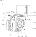
- FIG. 1 illustrates a perspective view of a protecting module for a laser welding device according to an embodiment of the present disclosure.
- FIG. 2 illustrates a front view of a protecting module for a laser welding device according to an embodiment of the present disclosure.
- a laser welding device 10 may include a main housing 100 to which various components for generating and emitting a laser beam are mounted, an optical system housing 300 which is coupled to one side of the main housing 100 to accommodate an optical system such as lenses, and a protecting module 500 which is disposed in front of the main housing 100 to protect the optical system.
- the main housing 100 has, in an embodiment, an approximate box shape, and the optical system housing 300 and the protecting module 500 are coupled to a front surface of the main housing 100.
- an optical system component such as a lens for emitting laser is disposed inside the optical system housing 300, and protective glass 310 is coupled to a front surface of the optical system housing 300.
- the protective glass 310 may be a kind of a shielding wall for protecting the optical system component.
- the protective glass 310 allows the laser beam emitted from an optical system to pass therethrough but prevents foreign substances such as spatter or fume generated during laser welding from entering the optical system (see FIG. 4 ).
- the protecting module 500 may be mounted.
- FIG. 3 illustrates a perspective view showing, in one direction, main parts of a protecting module for a laser welding device according to embodiments of the present disclosure.
- FIG. 4 illustrates a perspective view showing, in another direction, the main parts of the protecting module for a laser welding device according to the embodiment of the present disclosure.
- FIG. 5 illustrates a perspective view showing an air flow path of the protecting module for a laser welding device according to an embodiment of the present disclosure.
- FIG. 3 is an exploded view showing a protecting module with features according to embodiments of the present invention.
- the protecting module 500 comprises a first cover (560) and a second cover (570), wherein one of the first cover or the second cover comprises a plurality of air supply units (590), though which air can flow, installed on the outer circumferential surface of one of the first cover or the second cover.
- Each of the first cover and the second cover comprises an aperture through which a laser beam can pass.
- the protecting module is coupled to a laser welding device, and when the latter is in operation, the laser beam passes through protective glass (310) of the welding device (10).
- a welding device comprises a main housing (100), an optical system housing (300) and protective glass (310).
- the second cover is coupled to the optical system housing (300) that supports the protective glass.
- the first cover or the second cover comprises an air flow path (562).
- the air flow path (562) is a channel which is recessed from a plate surface on one side of the cover.
- a plurality of air holes (564) which pass through the cover allow the air flow path (562) and the outer circumferential surface to be in fluid communication with each other, and the air supply units (590) are in fluid communication with the air holes.
- the air flow path is located on a side of the first cover which faces the second cover. In another embodiment, the air flow path is located on a side of the second cover which faces the first cover.
- the second cover may further comprise a sealing member (580), which, when the protective module is coupled with the welding device, is inserted between the second cover and the optical system housing.
- the second cover further comprises a sealing section (572) which is recessed in a plate surface of the second cover and may receive the sealing member (580).
- the first cover may further comprise a plurality of fastening holes (568).
- the protecting module may further comprise a reflect light-absorbing plate (550).
- the protecting device may further comprise a fixing frame (510) for coupling to the main housing. The details of the fixing frame and features associated with it in other embodiments are described below.
- the exploded view in Figure 3 further illustrates additional features which may be provided in other embodiments, including a fixing frame 510 coupled to the main housing 100, a sliding frame 520 movably coupled to the fixing frame 510, and a support frame 530 movably coupled to the sliding frame 520.
- a lamp 540 may be coupled to the support frame 530.
- the protecting module 500 may include a reflected light-absorbing plate 550 disposed in front of the optical system housing 300 and a cover assembly disposed between the reflected light-absorbing plate 550 and the optical system housing 300.
- the cover assembly represents a part in which a first cover 560 and a second cover 570 are coupled to each other.
- the first cover 560 is connected to a plurality of air supply units 590, and a sealing member 580 is inserted between the second cover 570 and the optical system housing 300.
- the fixing frame 510 As illustrated in FIGS. 1 to 4 , the fixing frame 510, as included in some embodiments, has an approximately 'U'-shape in which both ends thereof are bent forward to face each other. A movement slit 512 is provided in each of the facing ends of the fixing frame 510, and a central section of the fixing frame 510 is coupled to the main housing 100 by a plurality of fastening members 514.
- the fastening members 514 may be provided as a coupling pin, a bolt, or the like.
- the movement slit 512 passes through each of the bent ends of the fixing frame 510 and has a certain length in a longitudinal direction. As the sliding frame 520 slides along the movement slit 512, the support frame 530 is close to or away from the first cover 560. Accordingly, an installation position of the lamp 540 installed in the support frame 530 may be adjusted.
- the sliding frame 520 is provided in a pair and movably coupled to the respective one of the movement slits 512.
- the sliding frames 520 have a straight bar shape and are disposed along the longitudinal direction of the movement slits 512.
- a cylindrical connection pin 522 is coupled to between the pair of the sliding frames 520 (inner surfaces thereof), and thus, the sliding frames 520 are connected to each other to move as a single body.
- a sliding pin 524 is coupled to each of end portions of the sliding frames 520 spaced apart from a region into which the connection pin 522 is inserted.
- Each of the sliding pins 524 is disposed protruding from an outer surface of the sliding frame 520 toward the movement slit 512.
- the sliding pin 524 includes a pin body 524a coupled to the sliding frame 520 and a pin head 524b protruding outward from the movement slit 512.
- the pin body 524a and the pin head 524b are integrated with each other, and a diameter of the pin head 524b is greater than a diameter of the pin body 524a and a width of the movement slit 512.
- the sliding pin 524 is inserted into the movement slit 512 and is fixed to the sliding frame 520 in a state in which the sliding frame 520 is disposed along the movement slit 512, and thus, the sliding frames 520 may be movably coupled to the movement slits 512 of the fixing frame 510.
- the support frame 530 is coupled to the sliding frame 520.
- the support frame 530 is disposed to be perpendicular to a front end portion of the sliding frame 520. Also, the support frame 530 is disposed in parallel to the first cover 560. Since the sliding frame 520 is provided in a pair, the support frame 530 is also provided in a pair and coupled to the respective one of the end portions of the sliding frames 520.
- the support frame 530 has a bar shape having a certain width, and adjustment slit 532 passes through one end thereof in a width direction.
- An adjustment pin 534 is inserted into the adjustment slit 532, and thus, the support frame 530 is movably coupled to the sliding frame 520.
- the adjustment pin 534 has the same type as the sliding pin 524, and when the support frame 530 is moved in the width direction in a state in which the adjustment slit 532 is constrained by the adjustment pin 534, a position of the support frame 530 is adjusted. As the position of the support frame 530 changes, a position of the lamp 540 mounted to the support frame 530 also changes.
- a support bracket 536 for mounting the lamp 540 is coupled to a front surface of the support frame 530.
- the support bracket 536 is fixed on the support frame 530, and the other end thereof is bent at right angle and extends.
- the support bracket 536 is provided in a pair, and the pair of support brackets 536 are fixed on the support frame 530 in a state of being spaced apart from each other by a distance corresponding to a length of the lamp 540.
- the support brackets 536 are installed such that the portions extending at right angle face each other in parallel, and the lamp 540 is inserted between the extended portions and coupled to the support brackets 536.
- the lamp 540 has a cuboidal shape and coupled between the pair of support brackets 536.
- the lamp 540 may be embodied as LED, etc., and a substrate (not shown) for operation, a power connector (not shown) for connection with an external power supply, or the like may be built therein.
- the lamp 540 is provided to monitor the particular wavelength band and is used to check welding quality. That is, the lamp 540 for emitting light corresponding to a wavelength band of the laser beam is utilized, and thus, the laser welding quality may be checked.
- the reflected light-absorbing plate 550 is disposed behind the lamp 540.
- the reflected light-absorbing plate 550 has a disc shape and absorbs a reflected beam generated during laser welding to prevent peripheral components from be damaged by the reflected light.
- the reflected light-absorbing plate 550 may be made of a material such as steel, and the surface thereof may be treated to have dark color through an anodizing method or the like.
- the reflected light-absorbing plate 550 may be treated to have black color so that the reflected beam may be easily absorbed. Thus, the occurrence of back reflection of the laser may be reduced as much as possible.
- the reflected light-absorbing plate 550 includes the material such as the steel, and thus, a magnetic body may be attached to a surface thereof. Using this characteristics, a displacement sensor (not shown) provided with a magnet may be attached to the reflected light-absorbing plate 550. A focal length of laser may be easily measured by attaching the displacement sensor to the reflected light-absorbing plate 550, and thus, the precision when the optical system of the laser welding device is set may be enhanced.
- a through-hole is provided in a plate surface of the reflected light-absorbing plate 550 so that the laser beam may pass therethrough.
- a plurality of plate slits 552 for discharging air sprayed from the cover assembly pass through an edge of the plate surface of the reflected light-absorbing plate 550.
- each of the plate slits 552 has a streamline shape, which may correspond to a shape of the edge of the reflected light-absorbing plate 550, and the plurality of plate slits 552 are disposed spaced apart from each other without contacting each other.
- the air sprayed from the cover assembly is moved along the plate slits 552 and then discharged toward an edge of the reflected light-absorbing plate 550.
- there an air flow path air current
- air current may be provided, which allows the air sprayed from the cover assembly to escape from the cover assembly to the outside of the reflected light-absorbing plate 550.
- the reflected light-absorbing plate 550 is tightly coupled to the first cover 560.
- the cover assembly includes the first cover 560 and the second cover 570.
- the cover assembly may be coupled to the sliding frame 520 or the support frame 530.
- the cover assembly is coupled to the optical system housing 300 separately, and the fixing frame 510 is coupled to the main housing 100.
- the cover assembly is first coupled to the main housing 100 in a state of being coupled to the sliding frame 520 or the support frame 530, and then, the cover assembly may be coupled to the optical system housing 300.
- the first cover 560 has a disc shape having a certain thickness and has a ring shape in which an aperture is provided to allow the laser beam to pass therethrough.
- an air flow path 562 and an air hole 564 are provided in a rear surface of the first cover 560 coupled to the second cover 570.
- a plate insertion section 566 for supporting the reflected light-absorbing plate 550 is provided in a front surface thereof.
- the air flow path 562 has a ring shape along the ring-shaped rear surface of the first cover 560 and is recessed from the rear surface thereof.
- the plurality of air supply units 590 having a tube or pipe shape are connected to an outer circumferential surface of the first cover 560.
- Each of the air supply units 590 may communicate with the air flow path 562 through a plurality of air holes 564.
- the air flow path 562 provides a flow path allowing the air, which is supplied through the air supply units 590 and the air hole 564, to flow.
- the air flowing into the air flow path 562 is discharged between the first cover 560 and the second cover 570 and forms an "air knife” to block foreign substances. The concept of the "air knife” and its operation will be described later.
- the air hole 564 is a through-hole for connecting the air flow path 562 and the outer circumferential surface and passes through a position corresponding to the air supply unit 590.
- the air holes 564 may be provided to correspond to the number and positions of the air supply units 590.
- the plate insertion section 566 is recessed from the front surface of the first cover 560 and has a shape corresponding to the size and shape of the reflected light-absorbing plate 550.
- the front surface of the first cover 560 is positioned on the same plane as a front surface of the reflected light-absorbing plate 550. That is, in the state where the reflected light-absorbing plate 550 is inserted into the plate insertion section 566, the front surface of the first cover 560 become flat with no height difference from the reflected light-absorbing plate 550.
- the second cover 570 is coupled to the rear surface of the first cover 560 by a plurality of fastening members (not shown). To this end, a plurality of fastening holes 568 may pass through an edge of the plate surface of the first cover 560.
- the second cover 570 includes a ring-shaped plate material having a certain thickness.
- a front surface of the second cover 570 may have a flat shape, and a plurality of fastening holes 574 may pass through an edge of the front surface thereof to establish the connection with the first cover 560.
- a sealing section 572, into which the sealing member 580 is inserted, may be provided in a rear surface of the second cover 570.
- the sealing section 572 has a groove shape corresponding to a shape of the sealing member 580 and may be recessed from the rear surface of the second cover 570.
- the sealing section 572 protrudes from the rear surface of the second cover 570, and this protrusion section has a groove into which the sealing member 580 is inserted.
- the protrusion section is inserted into the optical system housing 300, and thus, when the cover assembly is coupled to the optical system housing 300, the second cover 570 comes into close contact with the optical system housing 300.
- the sealing member 580 has a ring shape and provides sealing between the second cover 570 and the optical system housing 300. In a state of being inserted into the sealing section 572, the sealing member 580 may protrude slightly from the sealing section 572. Accordingly, when the second cover 570 and the optical system housing 300 are coupled to each other, sealing characteristics are enhanced as the sealing member 580 is pressed.
- FIG. 6 illustrates a perspective view showing a form of air spraying in the protecting module for a laser welding device according to an embodiment of the present disclosure.
- the paths through which the air flows into, moves, and is discharged are illustrated by arrows in FIG. 6 .
- the air flowing into the first cover 560 is discharged toward the inner circumferential surface of the cover assembly through a space A between mating surfaces of the first cover 560 and the second cover 570.
- the space A between the mating surfaces on the inner circumferential surface sides of the first cover 560 and the second cover 570 is not completely closed but has a gap sufficient to allow the air to be discharged.
- the external air flowing into the first cover 560 is discharged toward the gap (to the apertures) of the space A between the mating surfaces of the first cover 560 and the second cover 570.
- the air to be discharged is circularly discharged along the shape of the inner circumferential surface of the cover assembly. This air being discharged serves as a curtain for blocking the inner circumferential surface side of the cover assembly, and thus, when the air being discharged has an effect similar to that of forming an air membrane, the air is defined as an air curtain or an air knife.
- the air forming the air knife moves toward the front surface of the first cover 560 because the second cover 570 is closed, and is then guided to the outside of the reflected light-absorbing plate 550 through the aperture and the plate slit 552 of the reflected light-absorbing plate 550 and discharged to the outside of the cover assembly.
- the air knife has no effect on emission of the laser beam having strong straightness.
- fine foreign substances such as spatter or fume generated during the laser welding are not allowed to flow toward the optical system housing 300 by the air knife but blocked.
- the air knife may prevent foreign substances from being attached on the protective glass 310 mounted to the front surface of the optical system housing 300 and protect the protective glass 310.
- the laser welding device is provided with the protecting module 500 capable of forming the air knife, and thus, there is the effect of preventing the protective glass 310 from being contaminated and protecting the protective glass 310. Since the contamination of the protective glass 310 is prevented, there is the effect of making it possible to reduce loss due to the cleaning, maintain the quality of the protective glass 310, and increase the replacement cycle of the protective glass 310.
- the protecting module 500 is provided with the reflected light-absorbing plate 550 made of the metal material and absorbs the reflected beam generated during the laser welding, and thus, the occurrence of back reflection of the laser beam may be reduced as much as possible. Also, since the displacement sensor for measuring the focal length of laser may be attached to the reflected light-absorbing plate 550, a separate sensor mounting mechanism is not necessary. Since the displacement sensor may be easily mounted, there is the effect of enhancing the precision when the laser welding device 10 is set.
- the protecting module 500 of the present disclosure is provided with the lamp 540, the welding quality in the particular wavelength band may be monitored.
- the air is sprayed from the inside of the first cover and the second cover and allowed to flow toward the slits of the reflected light-absorbing plate disposed in front of the protective glass. Therefore, the protective glass is prevented from being contaminated.
- the absorbing plate for absorbing the reflected laser beam is installed in the front of the protecting module, and thus, the light reflected during the welding is absorbed. Therefore, the damage of the components due to the reflected light is prevented.
- the absorbing plate is used as an attachment pad to which the displacement sensor for measuring the focal length of laser is attached. Therefore, the increase in the number of components is suppressed, and the structure is simplified.
- the embodiment of the present disclosure provides the protecting module for the laser welding device, which may use the simple structure to protect the optical system and be used for various purposes.
Landscapes
- Engineering & Computer Science (AREA)
- Physics & Mathematics (AREA)
- Optics & Photonics (AREA)
- Mechanical Engineering (AREA)
- Plasma & Fusion (AREA)
- Quality & Reliability (AREA)
- Laser Beam Processing (AREA)
Abstract
Description
- Embodiments relates to a protecting module for a laser welding device.
- In general, as portable wireless devices such as video cameras, mobile phones, and portable computers become light-weight and equipped with high level functions, a lot of researches have been made on secondary batteries used as a driving power source. Such secondary batteries include, for example, a nickel-cadmium battery, a nickel-hydrogen battery, a nickel-zinc battery, a lithium battery, and the like. Among these batteries, the lithium secondary battery is rechargeable, can be small in size but with high capacity, and has high operating voltage and high energy density per unit weight, and thus, the lithium secondary battery has been widely used in high-tech electronic devices.
- Since various parts in the lithium secondary battery need to be welded during a manufacturing process, an ultrasonic welding device, a laser welding device, or the like is used to perform a welding process. Among the welding devices, one example of the laser welding device is disclosed in Korean Patent Publication No.
2018-0096910 (publication date: August 30, 2018 - The above information disclosed in this Background section is only for enhancement of understanding of the background of the described technology, and therefore it may contain information that does not form the related art.
- An aspect of the present invention provides a protecting module for a laser welding device, which protects an optical system of the laser welding device from spatter or fume generated during laser welding.
- According to at least one of embodiments, a protecting module for a laser welding device includes: a first cover having a hollow hole which allows a laser beam, which is emitted by passing through protective glass of the laser welding device, to pass therethrough; a second cover which is provided on one side of a main housing of the laser welding device in a coupled state with the first cover, is coupled to an optical system housing that supports the protective glass, and has a hollow hole that allows the laser beam to pass therethrough; and a plurality of air supply units which are installed on an outer circumferential surface of the first cover or the second cover and through which outside air flows into, wherein the first cover or the second cover includes an air flow path which is recessed from a plate surface on one side thereof and a plurality of air holes which pass therethrough to allow the air flow path and the outer circumferential surface to communicate with each other, and the air supply units communicate with the air holes, wherein the air supplied to the air flow path is discharged to a space between mating surfaces of the first cover and the second cover, wherein the air is discharged toward the hollow hole.
- The first cover and the second cover may have a disc shape and the hollow holes, and the air flow path may have a ring shape and be provided in the plate surface of the first cover or the second cover.
- The protecting module may further include a reflected light-absorbing plate which is coupled to a plate surface of the first cover on the opposite side from the second cover, has a hole which allows the laser beam to pass therethrough, and has black color.
- The reflected light-absorbing plate may include a metal material to which a magnetic body is attached by a magnetic force.
- The reflected light-absorbing plate may have a disc shape and have a plurality of streamline-shaped plate slits which pass therethrough and are spaced apart from each other along an outer edge.
- The protecting module may further include a sealing member which has a ring shape and is inserted between the optical system housing and the second cover to provide sealing between the optical system housing and the second cover.
- A sealing section, into which the sealing member is inserted, may be recessed from a plate surface on one side of the second cover.
- The protecting module may further include: a fixing frame which is coupled to one side of a main frame of the laser welding device, is disposed adjacent to the optical system housing, and has both ends bent into a 'U'-shape; sliding frames, each of which has a straight shape and is slidably coupled to a respective one of both bent ends of the fixing frame; and support frames, each of which is coupled to a respective one of the sliding frames and disposed in parallel to the first cover.
- The protecting module may further include lamps, each of which is coupled to a respective one of the support frames and emits light corresponding to a wavelength of the laser beam.
- The term "hollow hole" and "aperture" refer to the same feature and may be used interchangeably.
- The term "communicate" has the meaning of being "in fluid communication", fluid referring to either a liquid or a gas. The terms "communicate with" and "be in fluid communication with" have the same meaning and may be used interchangeably.
- At least some of the above features that accord with the invention and other features according to the invention are set out in the claims.
- The accompanying drawings are included to provide a further understanding of the present disclosure, and are incorporated in and constitute a part of this specification. The drawings illustrate embodiments of the present disclosure and, together with the description, serve to explain principles of the present disclosure. In the drawings:
-
FIG. 1 illustrates a perspective view of a protecting module for a laser welding device according to an embodiment of the present disclosure; -
FIG. 2 illustrates a front view of a protecting module for a laser welding device according to an embodiment of the present disclosure; -
FIG. 3 illustrates a perspective view showing, in one direction, main parts of a protecting module for a laser welding device according to an embodiment of the present disclosure; -
FIG. 4 illustrates a perspective view showing, in another direction, the main parts of the protecting module for a laser welding device according to the embodiment of the present disclosure; -
FIG. 5 illustrates a perspective view showing an air flow path of the protecting module for a laser welding device according to an embodiment of the present disclosure; and -
FIG. 6 illustrates a perspective view showing a form of air spraying in the protecting module for a laser welding device according to the present disclosure. - The embodiments of the present disclosure are provided to describe the present disclosure to those of ordinary skill in the art. The following embodiments may be modified to various types, and the scope of the present disclosure is not limited to the following embodiments. In the drawings, the thickness and size of each layer are exaggerated for convenience of explanation and clarity, and like reference numerals refer to like elements throughout. As used in this specification, the term "and/or" includes any and all combinations of one or more of the associated listed items. Also, in this specification, it will be understood that when an element A is referred to as being "connected to" an element B, the element A can be directly connected to the element B, or an intervening element C may be present between the elements A and B so that the element A can be indirectly connected to the element B.
- The terminology used herein is for the purpose of describing particular embodiments only and is not intended to be limiting of the disclosure. As used herein, the singular forms are intended to include the plural forms as well, unless the context clearly indicates otherwise. Also, it will be further understood that the terms "comprise or include" and/or "comprising or including," when used in this specification, specify the presence of stated features, numbers, steps, operations, members, elements, and/or groups thereof, but do not preclude the presence or addition of one or more other features, numbers, steps, operations, members, elements, and/or groups thereof.
- It will be understood that, although the terms first, second, etc. may be used herein to describe various members, components, regions, layers and/or sections, these members, components, regions, layers and/or sections should not be limited by these terms. These terms are only used to distinguish one member, component, region, layer and/or section from another. Thus, a first member, a first component, a first region, a first layer and/or a first section discussed below could be termed a second member, a second component, a second region, a second layer and/or a second section without departing from the teachings of the present disclosure.
- Spatially relative terms, such as "beneath," "below," "lower," "above," "upper," and the like, may be used herein for ease of description to describe one element or feature's relationship to another element(s) or feature(s) as illustrated in the figures. It will be understood that the spatially relative terms are intended to encompass different orientations of the device in use or operation in addition to the orientation depicted in the figures. For example, if the device in the figures is turned over, elements described as "beneath" or "below" other elements or features would then be oriented "above" or "upper" the other elements or features. Thus, the term "beneath" can encompass both an orientation of "above" and "below".
- Hereinafter, embodiments will be described in detail with reference to the accompanying drawings. For convenience, hereinafter, the description will be made assuming that the side near a protecting module of a laser welding device is defined as front, and the side near a main housing is defined as rear.
-
FIG. 1 illustrates a perspective view of a protecting module for a laser welding device according to an embodiment of the present disclosure.FIG. 2 illustrates a front view of a protecting module for a laser welding device according to an embodiment of the present disclosure. - As illustrated in
FIGS. 1 and2 , alaser welding device 10 may include amain housing 100 to which various components for generating and emitting a laser beam are mounted, anoptical system housing 300 which is coupled to one side of themain housing 100 to accommodate an optical system such as lenses, and a protectingmodule 500 which is disposed in front of themain housing 100 to protect the optical system. - The
main housing 100 has, in an embodiment, an approximate box shape, and the optical system housing 300 and the protectingmodule 500 are coupled to a front surface of themain housing 100. - In an embodiment, an optical system component such as a lens for emitting laser is disposed inside the
optical system housing 300, andprotective glass 310 is coupled to a front surface of theoptical system housing 300. - The
protective glass 310 may be a kind of a shielding wall for protecting the optical system component. Theprotective glass 310 allows the laser beam emitted from an optical system to pass therethrough but prevents foreign substances such as spatter or fume generated during laser welding from entering the optical system (seeFIG. 4 ). - Thus, since the foreign substances are attached to the
protective glass 310, periodic cleaning is necessary. However, if theprotective glass 310 is cleaned frequently, micro damage may occur in theprotective glass 310. - Also, when there are scratches on the
protective glass 310 due to the foreign substances and increases in damage, the replacement cycle of theprotective glass 310 becomes shorter, and theprotective glass 310 may be broken if not replaced. Thus, since theprotective glass 310 needs to be replaced periodically, the maintenance costs may increase. To prevent the damage to theprotective glass 310 due to the cleaning and an increase in costs due to the shortened replacement cycle, the protectingmodule 500 may be mounted. -
FIG. 3 illustrates a perspective view showing, in one direction, main parts of a protecting module for a laser welding device according to embodiments of the present disclosure.FIG. 4 illustrates a perspective view showing, in another direction, the main parts of the protecting module for a laser welding device according to the embodiment of the present disclosure.FIG. 5 illustrates a perspective view showing an air flow path of the protecting module for a laser welding device according to an embodiment of the present disclosure. -
FIG. 3 is an exploded view showing a protecting module with features according to embodiments of the present invention. The protectingmodule 500 comprises a first cover (560) and a second cover (570), wherein one of the first cover or the second cover comprises a plurality of air supply units (590), though which air can flow, installed on the outer circumferential surface of one of the first cover or the second cover. Each of the first cover and the second cover comprises an aperture through which a laser beam can pass. When the protecting module is coupled to a laser welding device, and when the latter is in operation, the laser beam passes through protective glass (310) of the welding device (10). Typically such a welding device comprises a main housing (100), an optical system housing (300) and protective glass (310). When the protecting module is coupled to a laser welding device, the second cover is coupled to the optical system housing (300) that supports the protective glass. The first cover or the second cover comprises an air flow path (562). The air flow path (562) is a channel which is recessed from a plate surface on one side of the cover. A plurality of air holes (564) which pass through the cover allow the air flow path (562) and the outer circumferential surface to be in fluid communication with each other, and the air supply units (590) are in fluid communication with the air holes. In an embodiment, the air flow path is located on a side of the first cover which faces the second cover. In another embodiment, the air flow path is located on a side of the second cover which faces the first cover. - In another embodiment, the second cover may further comprise a sealing member (580), which, when the protective module is coupled with the welding device, is inserted between the second cover and the optical system housing. In another embodiment, the second cover further comprises a sealing section (572) which is recessed in a plate surface of the second cover and may receive the sealing member (580). In another embodiment, the first cover may further comprise a plurality of fastening holes (568). In an embodiment, the protecting module may further comprise a reflect light-absorbing plate (550). In another embodiment, the protecting device may further comprise a fixing frame (510) for coupling to the main housing. The details of the fixing frame and features associated with it in other embodiments are described below.
- The exploded view in
Figure 3 further illustrates additional features which may be provided in other embodiments, including a fixingframe 510 coupled to themain housing 100, a slidingframe 520 movably coupled to the fixingframe 510, and asupport frame 530 movably coupled to the slidingframe 520. In an embodiment, alamp 540 may be coupled to thesupport frame 530. Also, the protectingmodule 500 may include a reflected light-absorbingplate 550 disposed in front of theoptical system housing 300 and a cover assembly disposed between the reflected light-absorbingplate 550 and theoptical system housing 300. The cover assembly represents a part in which afirst cover 560 and asecond cover 570 are coupled to each other. Thefirst cover 560 is connected to a plurality ofair supply units 590, and a sealingmember 580 is inserted between thesecond cover 570 and theoptical system housing 300. - As illustrated in
FIGS. 1 to 4 , the fixingframe 510, as included in some embodiments, has an approximately 'U'-shape in which both ends thereof are bent forward to face each other. A movement slit 512 is provided in each of the facing ends of the fixingframe 510, and a central section of the fixingframe 510 is coupled to themain housing 100 by a plurality offastening members 514. Thefastening members 514 may be provided as a coupling pin, a bolt, or the like. - The movement slit 512 passes through each of the bent ends of the fixing
frame 510 and has a certain length in a longitudinal direction. As the slidingframe 520 slides along the movement slit 512, thesupport frame 530 is close to or away from thefirst cover 560. Accordingly, an installation position of thelamp 540 installed in thesupport frame 530 may be adjusted. - As illustrate in
FIGS. 1 to 4 , the slidingframe 520 is provided in a pair and movably coupled to the respective one of the movement slits 512. The slidingframes 520 have a straight bar shape and are disposed along the longitudinal direction of the movement slits 512. - In an embodiment, a
cylindrical connection pin 522 is coupled to between the pair of the sliding frames 520 (inner surfaces thereof), and thus, the slidingframes 520 are connected to each other to move as a single body. A slidingpin 524 is coupled to each of end portions of the slidingframes 520 spaced apart from a region into which theconnection pin 522 is inserted. - Each of the sliding
pins 524 is disposed protruding from an outer surface of the slidingframe 520 toward the movement slit 512. The slidingpin 524 includes apin body 524a coupled to the slidingframe 520 and apin head 524b protruding outward from the movement slit 512. Thepin body 524a and thepin head 524b are integrated with each other, and a diameter of thepin head 524b is greater than a diameter of thepin body 524a and a width of the movement slit 512. - The sliding
pin 524 is inserted into the movement slit 512 and is fixed to the slidingframe 520 in a state in which the slidingframe 520 is disposed along the movement slit 512, and thus, the slidingframes 520 may be movably coupled to the movement slits 512 of the fixingframe 510. Thesupport frame 530 is coupled to the slidingframe 520. - As illustrated in
FIGS. 1 to 4 , in an embodiment, thesupport frame 530 is disposed to be perpendicular to a front end portion of the slidingframe 520. Also, thesupport frame 530 is disposed in parallel to thefirst cover 560. Since the slidingframe 520 is provided in a pair, thesupport frame 530 is also provided in a pair and coupled to the respective one of the end portions of the sliding frames 520. - In an embodiment, the
support frame 530 has a bar shape having a certain width, and adjustment slit 532 passes through one end thereof in a width direction. Anadjustment pin 534 is inserted into the adjustment slit 532, and thus, thesupport frame 530 is movably coupled to the slidingframe 520. Theadjustment pin 534 has the same type as the slidingpin 524, and when thesupport frame 530 is moved in the width direction in a state in which the adjustment slit 532 is constrained by theadjustment pin 534, a position of thesupport frame 530 is adjusted. As the position of thesupport frame 530 changes, a position of thelamp 540 mounted to thesupport frame 530 also changes. - In an embodiment, a
support bracket 536 for mounting thelamp 540 is coupled to a front surface of thesupport frame 530. - One end of the
support bracket 536 is fixed on thesupport frame 530, and the other end thereof is bent at right angle and extends. Thesupport bracket 536 is provided in a pair, and the pair ofsupport brackets 536 are fixed on thesupport frame 530 in a state of being spaced apart from each other by a distance corresponding to a length of thelamp 540. Thesupport brackets 536 are installed such that the portions extending at right angle face each other in parallel, and thelamp 540 is inserted between the extended portions and coupled to thesupport brackets 536. - As illustrated in
FIGS. 1 and2 , in an embodiment, thelamp 540 has a cuboidal shape and coupled between the pair ofsupport brackets 536. Thelamp 540 may be embodied as LED, etc., and a substrate (not shown) for operation, a power connector (not shown) for connection with an external power supply, or the like may be built therein. Thelamp 540 is provided to monitor the particular wavelength band and is used to check welding quality. That is, thelamp 540 for emitting light corresponding to a wavelength band of the laser beam is utilized, and thus, the laser welding quality may be checked. - Also, in an embodiment, the reflected light-absorbing
plate 550 is disposed behind thelamp 540. - As illustrated in
FIGS. 3 and4 , in an embodiment, the reflected light-absorbingplate 550 has a disc shape and absorbs a reflected beam generated during laser welding to prevent peripheral components from be damaged by the reflected light. The reflected light-absorbingplate 550 may be made of a material such as steel, and the surface thereof may be treated to have dark color through an anodizing method or the like. The reflected light-absorbingplate 550 may be treated to have black color so that the reflected beam may be easily absorbed. Thus, the occurrence of back reflection of the laser may be reduced as much as possible. - In an embodiment, the reflected light-absorbing
plate 550 includes the material such as the steel, and thus, a magnetic body may be attached to a surface thereof. Using this characteristics, a displacement sensor (not shown) provided with a magnet may be attached to the reflected light-absorbingplate 550. A focal length of laser may be easily measured by attaching the displacement sensor to the reflected light-absorbingplate 550, and thus, the precision when the optical system of the laser welding device is set may be enhanced. - Also, a through-hole is provided in a plate surface of the reflected light-absorbing
plate 550 so that the laser beam may pass therethrough. In an embodiment, a plurality of plate slits 552 for discharging air sprayed from the cover assembly pass through an edge of the plate surface of the reflected light-absorbingplate 550. - In an embodiment, each of the plate slits 552 has a streamline shape, which may correspond to a shape of the edge of the reflected light-absorbing
plate 550, and the plurality of plate slits 552 are disposed spaced apart from each other without contacting each other. In operation, the air sprayed from the cover assembly is moved along the plate slits 552 and then discharged toward an edge of the reflected light-absorbingplate 550. Thus, there an air flow path (air current) may be provided, which allows the air sprayed from the cover assembly to escape from the cover assembly to the outside of the reflected light-absorbingplate 550. - In an embodiment, the reflected light-absorbing
plate 550 is tightly coupled to thefirst cover 560. - In an embodiment, as illustrated in
FIGS. 3 and6 , the cover assembly includes thefirst cover 560 and thesecond cover 570. Although not illustrated in the drawings, the cover assembly may be coupled to the slidingframe 520 or thesupport frame 530. When the protectingmodule 500 is installed, the cover assembly is coupled to theoptical system housing 300 separately, and the fixingframe 510 is coupled to themain housing 100. Alternatively, the cover assembly is first coupled to themain housing 100 in a state of being coupled to the slidingframe 520 or thesupport frame 530, and then, the cover assembly may be coupled to theoptical system housing 300. - As illustrated in
FIGS. 3 to 6 , in an embodiment, thefirst cover 560 has a disc shape having a certain thickness and has a ring shape in which an aperture is provided to allow the laser beam to pass therethrough. In a rear surface of thefirst cover 560 coupled to thesecond cover 570, anair flow path 562 and anair hole 564 are provided. In a front surface thereof, aplate insertion section 566 for supporting the reflected light-absorbingplate 550 is provided. - In an embodiment, the
air flow path 562 has a ring shape along the ring-shaped rear surface of thefirst cover 560 and is recessed from the rear surface thereof. The plurality ofair supply units 590 having a tube or pipe shape are connected to an outer circumferential surface of thefirst cover 560. Each of theair supply units 590 may communicate with theair flow path 562 through a plurality of air holes 564. Theair flow path 562 provides a flow path allowing the air, which is supplied through theair supply units 590 and theair hole 564, to flow. The air flowing into theair flow path 562 is discharged between thefirst cover 560 and thesecond cover 570 and forms an "air knife" to block foreign substances. The concept of the "air knife" and its operation will be described later. - The
air hole 564 is a through-hole for connecting theair flow path 562 and the outer circumferential surface and passes through a position corresponding to theair supply unit 590. The air holes 564 may be provided to correspond to the number and positions of theair supply units 590. - In an embodiment, the
plate insertion section 566 is recessed from the front surface of thefirst cover 560 and has a shape corresponding to the size and shape of the reflected light-absorbingplate 550. Thus, in a state where the reflected light-absorbingplate 550 is inserted, the front surface of thefirst cover 560 is positioned on the same plane as a front surface of the reflected light-absorbingplate 550. That is, in the state where the reflected light-absorbingplate 550 is inserted into theplate insertion section 566, the front surface of thefirst cover 560 become flat with no height difference from the reflected light-absorbingplate 550. - The
second cover 570 is coupled to the rear surface of thefirst cover 560 by a plurality of fastening members (not shown). To this end, a plurality offastening holes 568 may pass through an edge of the plate surface of thefirst cover 560. - Similar to the
first cover 560, in an embodiment, thesecond cover 570 includes a ring-shaped plate material having a certain thickness. A front surface of thesecond cover 570 may have a flat shape, and a plurality offastening holes 574 may pass through an edge of the front surface thereof to establish the connection with thefirst cover 560. Asealing section 572, into which the sealingmember 580 is inserted, may be provided in a rear surface of thesecond cover 570. - In an embodiment, the
sealing section 572 has a groove shape corresponding to a shape of the sealingmember 580 and may be recessed from the rear surface of thesecond cover 570. Alternatively, as illustrated inFIG. 3 , thesealing section 572 protrudes from the rear surface of thesecond cover 570, and this protrusion section has a groove into which the sealingmember 580 is inserted. In this case, the protrusion section is inserted into theoptical system housing 300, and thus, when the cover assembly is coupled to theoptical system housing 300, thesecond cover 570 comes into close contact with theoptical system housing 300. - As illustrated in
FIGS. 3 and4 , in an embodiment, the sealingmember 580 has a ring shape and provides sealing between thesecond cover 570 and theoptical system housing 300. In a state of being inserted into thesealing section 572, the sealingmember 580 may protrude slightly from thesealing section 572. Accordingly, when thesecond cover 570 and theoptical system housing 300 are coupled to each other, sealing characteristics are enhanced as the sealingmember 580 is pressed. - In the protecting module for a laser welding device according to an embodiment of the present disclosure having the configuration described above, a process in which the air knife is formed will be described in detail.
-
FIG. 6 illustrates a perspective view showing a form of air spraying in the protecting module for a laser welding device according to an embodiment of the present disclosure. The paths through which the air flows into, moves, and is discharged are illustrated by arrows inFIG. 6 . - As illustrated in
FIG. 6 , in a state where thefirst cover 560 and thesecond cover 570 are coupled to each other, air flows into theair flow path 562 from the outside through theair supply units 590 and the air holes 564 inside thefirst cover 560. Since the front surface of thesecond cover 570 is flat, the air introduced in the state where thesecond cover 570 is coupled to thefirst cover 560 moves within theair flow path 562. - The air flowing into the
first cover 560 is discharged toward the inner circumferential surface of the cover assembly through a space A between mating surfaces of thefirst cover 560 and thesecond cover 570. To this end, the space A between the mating surfaces on the inner circumferential surface sides of thefirst cover 560 and thesecond cover 570 is not completely closed but has a gap sufficient to allow the air to be discharged. - The external air flowing into the
first cover 560 is discharged toward the gap (to the apertures) of the space A between the mating surfaces of thefirst cover 560 and thesecond cover 570. The air to be discharged is circularly discharged along the shape of the inner circumferential surface of the cover assembly. This air being discharged serves as a curtain for blocking the inner circumferential surface side of the cover assembly, and thus, when the air being discharged has an effect similar to that of forming an air membrane, the air is defined as an air curtain or an air knife. - The air forming the air knife moves toward the front surface of the
first cover 560 because thesecond cover 570 is closed, and is then guided to the outside of the reflected light-absorbingplate 550 through the aperture and the plate slit 552 of the reflected light-absorbingplate 550 and discharged to the outside of the cover assembly. - Although the laser beam is emitted to the aperture of the cover assembly, the air knife has no effect on emission of the laser beam having strong straightness. However, fine foreign substances such as spatter or fume generated during the laser welding are not allowed to flow toward the
optical system housing 300 by the air knife but blocked. Thus, the air knife may prevent foreign substances from being attached on theprotective glass 310 mounted to the front surface of theoptical system housing 300 and protect theprotective glass 310. - As described above, the laser welding device according to the present disclosure is provided with the protecting
module 500 capable of forming the air knife, and thus, there is the effect of preventing theprotective glass 310 from being contaminated and protecting theprotective glass 310. Since the contamination of theprotective glass 310 is prevented, there is the effect of making it possible to reduce loss due to the cleaning, maintain the quality of theprotective glass 310, and increase the replacement cycle of theprotective glass 310. - The protecting
module 500 is provided with the reflected light-absorbingplate 550 made of the metal material and absorbs the reflected beam generated during the laser welding, and thus, the occurrence of back reflection of the laser beam may be reduced as much as possible. Also, since the displacement sensor for measuring the focal length of laser may be attached to the reflected light-absorbingplate 550, a separate sensor mounting mechanism is not necessary. Since the displacement sensor may be easily mounted, there is the effect of enhancing the precision when thelaser welding device 10 is set. - Also, since the protecting
module 500 of the present disclosure is provided with thelamp 540, the welding quality in the particular wavelength band may be monitored. - In the embodiment of the present disclosure, the air is sprayed from the inside of the first cover and the second cover and allowed to flow toward the slits of the reflected light-absorbing plate disposed in front of the protective glass. Therefore, the protective glass is prevented from being contaminated.
- Also, the absorbing plate for absorbing the reflected laser beam is installed in the front of the protecting module, and thus, the light reflected during the welding is absorbed. Therefore, the damage of the components due to the reflected light is prevented. In addition, the absorbing plate is used as an attachment pad to which the displacement sensor for measuring the focal length of laser is attached. Therefore, the increase in the number of components is suppressed, and the structure is simplified.
- That is, the embodiment of the present disclosure provides the protecting module for the laser welding device, which may use the simple structure to protect the optical system and be used for various purposes.
- The above is merely an embodiment of the present disclosure, and thus, the present disclosure is not limited to the foregoing embodiment. Accordingly, it will be understood by those of ordinary skill in the art that various changes in form and details may be made without departing from the scope of the claims.
Claims (10)
- A protecting module for a laser welding device, the protecting module comprising:a first cover having an aperture which allows a laser beam, which is emitted by passing through protective glass of the laser welding device, to pass therethrough;a second cover which is provided on one side of a main housing of the laser welding device in a coupled state with the first cover, is coupled to an optical system housing that supports the protective glass, and has an aperture that allows the laser beam to pass therethrough; anda plurality of air supply units which are installed on an outer circumferential surface of the first cover or the second cover and through which outside air flows into,wherein the first cover or the second cover comprises an air flow path which is recessed from a plate surface on one side thereof and a plurality of air holes which pass therethrough to allow the air flow path and the outer circumferential surface to be in fluid communication with each other, and the air supply units are in fluid communication with the air holes,wherein the air supply units are configured to supply air to the air flow path, such that it is discharged to a space between mating surfaces of the first cover and the second cover and toward the apertures.
- The protecting module of claim 1, wherein the first cover and the second cover have a disc shape, and
the air flow path has a ring shape and is provided in the plate surface of the first cover or the second cover. - The protecting module of claim 2, further comprising a reflected light-absorbing plate which is coupled to a plate surface of the first cover on the opposite side from the second cover, has a hole which allows the laser beam to pass therethrough, and has black color.
- The protecting module of claim 3, wherein the reflected light-absorbing plate comprises a metal material to which a magnetic body is attached by a magnetic force.
- The protecting module of claim 3 or claim 4, wherein the reflected light-absorbing plate has a disc shape and has a plurality of streamline-shaped plate slits which pass therethrough and are spaced apart from each other along an outer edge.
- The protecting module of any preceding claim, further comprising a sealing member which has a ring shape and is inserted between the optical system housing and the second cover to provide sealing between the optical system housing and the second cover.
- The protecting module of claim 6, further comprising a sealing section, into which the sealing member is inserted, is recessed from a plate surface on one side of the second cover.
- The protecting module of any preceding claim, further comprising:a fixing frame which is coupled to one side of a main frame of the laser welding device, is disposed adjacent to the optical system housing, and has both ends bent to form a 'U'-shape;sliding frames, each of which has a straight shape and is slidably coupled to a respective one of both the bent ends of the fixing frame; andsupport frames, each of which is coupled to a respective one of the sliding frames and disposed in parallel to the first cover.
- The protecting module of claim 8, further comprising lamps, each of which is coupled to a respective one of the support frames and is configured to emit light corresponding to a wavelength of the laser beam.
- A laser welding arrangement comprising a laser welding device and a protecting module according to any preceding claim.
Applications Claiming Priority (1)
| Application Number | Priority Date | Filing Date | Title |
|---|---|---|---|
| KR1020190130505A KR102383193B1 (en) | 2019-10-21 | 2019-10-21 | Protecting module for laser welding device |
Publications (2)
| Publication Number | Publication Date |
|---|---|
| EP3812081A1 true EP3812081A1 (en) | 2021-04-28 |
| EP3812081B1 EP3812081B1 (en) | 2024-10-02 |
Family
ID=72964601
Family Applications (1)
| Application Number | Title | Priority Date | Filing Date |
|---|---|---|---|
| EP20202907.0A Active EP3812081B1 (en) | 2019-10-21 | 2020-10-20 | Protecting module for laser welding device |
Country Status (5)
| Country | Link |
|---|---|
| EP (1) | EP3812081B1 (en) |
| KR (1) | KR102383193B1 (en) |
| CN (1) | CN112692455B (en) |
| HU (1) | HUE069209T2 (en) |
| PL (1) | PL3812081T3 (en) |
Cited By (2)
| Publication number | Priority date | Publication date | Assignee | Title |
|---|---|---|---|---|
| CN113083778A (en) * | 2021-05-03 | 2021-07-09 | 深圳怪虫机器人有限公司 | Self-cleaning device for cleaning camera on robot |
| CN119820110A (en) * | 2024-12-18 | 2025-04-15 | 江苏时代新能源科技有限公司 | Laser welding nozzle and laser welding device |
Families Citing this family (5)
| Publication number | Priority date | Publication date | Assignee | Title |
|---|---|---|---|---|
| KR102603078B1 (en) * | 2021-09-03 | 2023-11-16 | 엔케이에스주식회사 | Apparatus For Assisting Laser-Assisted Materials Processing |
| CN114346419A (en) * | 2021-09-10 | 2022-04-15 | 苏州创鑫激光科技有限公司 | Laser processing apparatus |
| CN114473268B (en) * | 2022-03-21 | 2026-01-16 | 岗春激光科技(江苏)有限公司 | Laser processing head |
| KR102771651B1 (en) * | 2022-10-25 | 2025-02-24 | 주식회사휴비스 | Head protector for laser welding |
| KR102898566B1 (en) * | 2023-09-13 | 2025-12-09 | 주식회사 제이엘티 | Laser vision inspection sensor for welding |
Citations (4)
| Publication number | Priority date | Publication date | Assignee | Title |
|---|---|---|---|---|
| KR20030050457A (en) * | 2001-12-18 | 2003-06-25 | 현대자동차주식회사 | Air jet device of optic head for laser system |
| KR20140064443A (en) * | 2012-11-20 | 2014-05-28 | 주식회사 성우하이텍 | Protective glass unit for laser optic head |
| KR20180096910A (en) | 2017-02-22 | 2018-08-30 | 김인호 | Laser weading head integrated welding part monitor divice |
| US20190160592A1 (en) * | 2016-05-30 | 2019-05-30 | Honda Motor Co., Ltd. | Laser processing device |
Family Cites Families (13)
| Publication number | Priority date | Publication date | Assignee | Title |
|---|---|---|---|---|
| JPS61135497A (en) * | 1984-12-06 | 1986-06-23 | Nippon Steel Corp | Shielding device for stopping laser reflected beam |
| JPS6395690U (en) * | 1986-12-10 | 1988-06-20 | ||
| KR100357608B1 (en) * | 2000-11-22 | 2002-10-25 | 현대자동차주식회사 | Optic head of laser system |
| JP4699640B2 (en) * | 2001-06-13 | 2011-06-15 | ギガフォトン株式会社 | Wavelength measuring equipment for vacuum ultraviolet laser equipment |
| JP4947973B2 (en) * | 2005-06-02 | 2012-06-06 | ソニー株式会社 | Laser processing apparatus and processing method thereof, debris recovery mechanism and recovery method thereof |
| JP5194367B2 (en) * | 2006-02-20 | 2013-05-08 | 日産自動車株式会社 | Laser processing head and laser processing method |
| CN202344133U (en) * | 2011-11-28 | 2012-07-25 | 深圳市大族激光科技股份有限公司 | Anti-reflecting device for laser cutting machine |
| KR101841793B1 (en) * | 2013-11-29 | 2018-05-04 | 주식회사 엘지화학 | Laser Welding Apparatus |
| JP5866672B2 (en) * | 2014-01-22 | 2016-02-17 | トヨタ自動車株式会社 | Laser processing equipment |
| DE202015102740U1 (en) * | 2015-05-27 | 2016-08-31 | Uwe Bergmann | Laser welding device with spatter protection device |
| KR20180021968A (en) * | 2016-08-22 | 2018-03-06 | 에이피시스템 주식회사 | Air-pushing dust collector |
| CN108941939B (en) * | 2017-07-12 | 2020-04-07 | 温州大学激光与光电智能制造研究院 | Closed-loop laser processing quality control method based on molten pool splash detection |
| CN109759697B (en) * | 2019-01-31 | 2021-08-24 | 大族激光科技产业集团股份有限公司 | Laser processing lens protection device and laser processing equipment |
-
2019
- 2019-10-21 KR KR1020190130505A patent/KR102383193B1/en active Active
-
2020
- 2020-10-20 EP EP20202907.0A patent/EP3812081B1/en active Active
- 2020-10-20 HU HUE20202907A patent/HUE069209T2/en unknown
- 2020-10-20 PL PL20202907.0T patent/PL3812081T3/en unknown
- 2020-10-21 CN CN202011130000.5A patent/CN112692455B/en active Active
Patent Citations (4)
| Publication number | Priority date | Publication date | Assignee | Title |
|---|---|---|---|---|
| KR20030050457A (en) * | 2001-12-18 | 2003-06-25 | 현대자동차주식회사 | Air jet device of optic head for laser system |
| KR20140064443A (en) * | 2012-11-20 | 2014-05-28 | 주식회사 성우하이텍 | Protective glass unit for laser optic head |
| US20190160592A1 (en) * | 2016-05-30 | 2019-05-30 | Honda Motor Co., Ltd. | Laser processing device |
| KR20180096910A (en) | 2017-02-22 | 2018-08-30 | 김인호 | Laser weading head integrated welding part monitor divice |
Cited By (2)
| Publication number | Priority date | Publication date | Assignee | Title |
|---|---|---|---|---|
| CN113083778A (en) * | 2021-05-03 | 2021-07-09 | 深圳怪虫机器人有限公司 | Self-cleaning device for cleaning camera on robot |
| CN119820110A (en) * | 2024-12-18 | 2025-04-15 | 江苏时代新能源科技有限公司 | Laser welding nozzle and laser welding device |
Also Published As
| Publication number | Publication date |
|---|---|
| EP3812081B1 (en) | 2024-10-02 |
| CN112692455B (en) | 2023-05-12 |
| KR102383193B1 (en) | 2022-04-06 |
| PL3812081T3 (en) | 2025-01-13 |
| HUE069209T2 (en) | 2025-02-28 |
| CN112692455A (en) | 2021-04-23 |
| KR20210047002A (en) | 2021-04-29 |
Similar Documents
| Publication | Publication Date | Title |
|---|---|---|
| EP3812081B1 (en) | Protecting module for laser welding device | |
| US7192153B2 (en) | Lens, light irradiation apparatus, and laser pointer | |
| JP6639163B2 (en) | Vehicle lighting | |
| EP3722862A1 (en) | Laser radar system and control method thereof, method of obtaining scanning angle, and vehicle | |
| US11256164B2 (en) | Optical element and projection device using the same | |
| WO2019071659A1 (en) | Small split-type auto focus actuator with low power consumption | |
| JP2018056088A (en) | Lighting device | |
| US10530112B2 (en) | Solid-state laser device | |
| JP3089382B2 (en) | Laser oscillation device | |
| JP2008310237A (en) | Lens-driving device, camera and mobile phone with camera | |
| JP2014165882A (en) | Image sensor unit and method for manufacturing the same | |
| JP2013258356A (en) | Light source device | |
| CN115722796B (en) | Handheld welding gun, assembly method thereof and laser welding system | |
| CN217587849U (en) | Laser projection device | |
| CN219082906U (en) | Light guide assembly structure | |
| JP5702122B2 (en) | Light irradiation device for exposure equipment | |
| JP2006196972A (en) | Camera system | |
| CN220709475U (en) | Beam homogenizing assembly and laser emission device | |
| CN112596323A (en) | Lens module and electronic equipment with same | |
| CN209784722U (en) | Light pipe protective cover and light pipe assembly | |
| CN218158596U (en) | Laser beam combining device | |
| CN223644288U (en) | High-speed dynamic focus tracking laser scanning system | |
| CN217587855U (en) | Laser projection equipment | |
| CN220307262U (en) | Industrial camera debugging device and debugging platform | |
| CN217062828U (en) | Small light spot laser |
Legal Events
| Date | Code | Title | Description |
|---|---|---|---|
| PUAI | Public reference made under article 153(3) epc to a published international application that has entered the european phase |
Free format text: ORIGINAL CODE: 0009012 |
|
| STAA | Information on the status of an ep patent application or granted ep patent |
Free format text: STATUS: REQUEST FOR EXAMINATION WAS MADE |
|
| 17P | Request for examination filed |
Effective date: 20201020 |
|
| AK | Designated contracting states |
Kind code of ref document: A1 Designated state(s): AL AT BE BG CH CY CZ DE DK EE ES FI FR GB GR HR HU IE IS IT LI LT LU LV MC MK MT NL NO PL PT RO RS SE SI SK SM TR |
|
| AX | Request for extension of the european patent |
Extension state: BA ME |
|
| STAA | Information on the status of an ep patent application or granted ep patent |
Free format text: STATUS: EXAMINATION IS IN PROGRESS |
|
| 17Q | First examination report despatched |
Effective date: 20230719 |
|
| GRAP | Despatch of communication of intention to grant a patent |
Free format text: ORIGINAL CODE: EPIDOSNIGR1 |
|
| STAA | Information on the status of an ep patent application or granted ep patent |
Free format text: STATUS: GRANT OF PATENT IS INTENDED |
|
| INTG | Intention to grant announced |
Effective date: 20240429 |
|
| GRAS | Grant fee paid |
Free format text: ORIGINAL CODE: EPIDOSNIGR3 |
|
| GRAA | (expected) grant |
Free format text: ORIGINAL CODE: 0009210 |
|
| STAA | Information on the status of an ep patent application or granted ep patent |
Free format text: STATUS: THE PATENT HAS BEEN GRANTED |
|
| AK | Designated contracting states |
Kind code of ref document: B1 Designated state(s): AL AT BE BG CH CY CZ DE DK EE ES FI FR GB GR HR HU IE IS IT LI LT LU LV MC MK MT NL NO PL PT RO RS SE SI SK SM TR |
|
| REG | Reference to a national code |
Ref country code: GB Ref legal event code: FG4D |
|
| REG | Reference to a national code |
Ref country code: CH Ref legal event code: EP |
|
| REG | Reference to a national code |
Ref country code: DE Ref legal event code: R096 Ref document number: 602020038628 Country of ref document: DE |
|
| REG | Reference to a national code |
Ref country code: IE Ref legal event code: FG4D |
|
| REG | Reference to a national code |
Ref country code: LT Ref legal event code: MG9D |
|
| REG | Reference to a national code |
Ref country code: NL Ref legal event code: MP Effective date: 20241002 |
|
| REG | Reference to a national code |
Ref country code: HU Ref legal event code: AG4A Ref document number: E069209 Country of ref document: HU |
|
| REG | Reference to a national code |
Ref country code: AT Ref legal event code: MK05 Ref document number: 1728135 Country of ref document: AT Kind code of ref document: T Effective date: 20241002 |
|
| PG25 | Lapsed in a contracting state [announced via postgrant information from national office to epo] |
Ref country code: NL Free format text: LAPSE BECAUSE OF FAILURE TO SUBMIT A TRANSLATION OF THE DESCRIPTION OR TO PAY THE FEE WITHIN THE PRESCRIBED TIME-LIMIT Effective date: 20241002 |
|
| PG25 | Lapsed in a contracting state [announced via postgrant information from national office to epo] |
Ref country code: NL Free format text: LAPSE BECAUSE OF FAILURE TO SUBMIT A TRANSLATION OF THE DESCRIPTION OR TO PAY THE FEE WITHIN THE PRESCRIBED TIME-LIMIT Effective date: 20241002 |
|
| PG25 | Lapsed in a contracting state [announced via postgrant information from national office to epo] |
Ref country code: IS Free format text: LAPSE BECAUSE OF FAILURE TO SUBMIT A TRANSLATION OF THE DESCRIPTION OR TO PAY THE FEE WITHIN THE PRESCRIBED TIME-LIMIT Effective date: 20250202 Ref country code: HR Free format text: LAPSE BECAUSE OF FAILURE TO SUBMIT A TRANSLATION OF THE DESCRIPTION OR TO PAY THE FEE WITHIN THE PRESCRIBED TIME-LIMIT Effective date: 20241002 Ref country code: PT Free format text: LAPSE BECAUSE OF FAILURE TO SUBMIT A TRANSLATION OF THE DESCRIPTION OR TO PAY THE FEE WITHIN THE PRESCRIBED TIME-LIMIT Effective date: 20250203 |
|
| PG25 | Lapsed in a contracting state [announced via postgrant information from national office to epo] |
Ref country code: FI Free format text: LAPSE BECAUSE OF FAILURE TO SUBMIT A TRANSLATION OF THE DESCRIPTION OR TO PAY THE FEE WITHIN THE PRESCRIBED TIME-LIMIT Effective date: 20241002 |
|
| PG25 | Lapsed in a contracting state [announced via postgrant information from national office to epo] |
Ref country code: BG Free format text: LAPSE BECAUSE OF FAILURE TO SUBMIT A TRANSLATION OF THE DESCRIPTION OR TO PAY THE FEE WITHIN THE PRESCRIBED TIME-LIMIT Effective date: 20241002 |
|
| PG25 | Lapsed in a contracting state [announced via postgrant information from national office to epo] |
Ref country code: ES Free format text: LAPSE BECAUSE OF FAILURE TO SUBMIT A TRANSLATION OF THE DESCRIPTION OR TO PAY THE FEE WITHIN THE PRESCRIBED TIME-LIMIT Effective date: 20241002 |
|
| PG25 | Lapsed in a contracting state [announced via postgrant information from national office to epo] |
Ref country code: NO Free format text: LAPSE BECAUSE OF FAILURE TO SUBMIT A TRANSLATION OF THE DESCRIPTION OR TO PAY THE FEE WITHIN THE PRESCRIBED TIME-LIMIT Effective date: 20250102 |
|
| PG25 | Lapsed in a contracting state [announced via postgrant information from national office to epo] |
Ref country code: AT Free format text: LAPSE BECAUSE OF FAILURE TO SUBMIT A TRANSLATION OF THE DESCRIPTION OR TO PAY THE FEE WITHIN THE PRESCRIBED TIME-LIMIT Effective date: 20241002 Ref country code: LV Free format text: LAPSE BECAUSE OF FAILURE TO SUBMIT A TRANSLATION OF THE DESCRIPTION OR TO PAY THE FEE WITHIN THE PRESCRIBED TIME-LIMIT Effective date: 20241002 Ref country code: GR Free format text: LAPSE BECAUSE OF FAILURE TO SUBMIT A TRANSLATION OF THE DESCRIPTION OR TO PAY THE FEE WITHIN THE PRESCRIBED TIME-LIMIT Effective date: 20250103 |
|
| PG25 | Lapsed in a contracting state [announced via postgrant information from national office to epo] |
Ref country code: CZ Free format text: LAPSE BECAUSE OF FAILURE TO SUBMIT A TRANSLATION OF THE DESCRIPTION OR TO PAY THE FEE WITHIN THE PRESCRIBED TIME-LIMIT Effective date: 20241002 |
|
| PG25 | Lapsed in a contracting state [announced via postgrant information from national office to epo] |
Ref country code: RS Free format text: LAPSE BECAUSE OF FAILURE TO SUBMIT A TRANSLATION OF THE DESCRIPTION OR TO PAY THE FEE WITHIN THE PRESCRIBED TIME-LIMIT Effective date: 20250102 |
|
| REG | Reference to a national code |
Ref country code: CH Ref legal event code: PL |
|
| PG25 | Lapsed in a contracting state [announced via postgrant information from national office to epo] |
Ref country code: SM Free format text: LAPSE BECAUSE OF FAILURE TO SUBMIT A TRANSLATION OF THE DESCRIPTION OR TO PAY THE FEE WITHIN THE PRESCRIBED TIME-LIMIT Effective date: 20241002 |
|
| REG | Reference to a national code |
Ref country code: DE Ref legal event code: R097 Ref document number: 602020038628 Country of ref document: DE |
|
| PG25 | Lapsed in a contracting state [announced via postgrant information from national office to epo] |
Ref country code: MC Free format text: LAPSE BECAUSE OF FAILURE TO SUBMIT A TRANSLATION OF THE DESCRIPTION OR TO PAY THE FEE WITHIN THE PRESCRIBED TIME-LIMIT Effective date: 20241002 |
|
| PG25 | Lapsed in a contracting state [announced via postgrant information from national office to epo] |
Ref country code: DK Free format text: LAPSE BECAUSE OF FAILURE TO SUBMIT A TRANSLATION OF THE DESCRIPTION OR TO PAY THE FEE WITHIN THE PRESCRIBED TIME-LIMIT Effective date: 20241002 |
|
| PG25 | Lapsed in a contracting state [announced via postgrant information from national office to epo] |
Ref country code: BE Free format text: LAPSE BECAUSE OF NON-PAYMENT OF DUE FEES Effective date: 20241031 Ref country code: LU Free format text: LAPSE BECAUSE OF NON-PAYMENT OF DUE FEES Effective date: 20241020 |
|
| PG25 | Lapsed in a contracting state [announced via postgrant information from national office to epo] |
Ref country code: EE Free format text: LAPSE BECAUSE OF FAILURE TO SUBMIT A TRANSLATION OF THE DESCRIPTION OR TO PAY THE FEE WITHIN THE PRESCRIBED TIME-LIMIT Effective date: 20241002 |
|
| PG25 | Lapsed in a contracting state [announced via postgrant information from national office to epo] |
Ref country code: CH Free format text: LAPSE BECAUSE OF NON-PAYMENT OF DUE FEES Effective date: 20241031 |
|
| PG25 | Lapsed in a contracting state [announced via postgrant information from national office to epo] |
Ref country code: RO Free format text: LAPSE BECAUSE OF FAILURE TO SUBMIT A TRANSLATION OF THE DESCRIPTION OR TO PAY THE FEE WITHIN THE PRESCRIBED TIME-LIMIT Effective date: 20241002 |
|
| PG25 | Lapsed in a contracting state [announced via postgrant information from national office to epo] |
Ref country code: SK Free format text: LAPSE BECAUSE OF FAILURE TO SUBMIT A TRANSLATION OF THE DESCRIPTION OR TO PAY THE FEE WITHIN THE PRESCRIBED TIME-LIMIT Effective date: 20241002 |
|
| PG25 | Lapsed in a contracting state [announced via postgrant information from national office to epo] |
Ref country code: IT Free format text: LAPSE BECAUSE OF FAILURE TO SUBMIT A TRANSLATION OF THE DESCRIPTION OR TO PAY THE FEE WITHIN THE PRESCRIBED TIME-LIMIT Effective date: 20241002 |
|
| REG | Reference to a national code |
Ref country code: BE Ref legal event code: MM Effective date: 20241031 |
|
| PLBE | No opposition filed within time limit |
Free format text: ORIGINAL CODE: 0009261 |
|
| STAA | Information on the status of an ep patent application or granted ep patent |
Free format text: STATUS: NO OPPOSITION FILED WITHIN TIME LIMIT |
|
| PG25 | Lapsed in a contracting state [announced via postgrant information from national office to epo] |
Ref country code: SE Free format text: LAPSE BECAUSE OF FAILURE TO SUBMIT A TRANSLATION OF THE DESCRIPTION OR TO PAY THE FEE WITHIN THE PRESCRIBED TIME-LIMIT Effective date: 20241002 |
|
| 26N | No opposition filed |
Effective date: 20250703 |
|
| PGFP | Annual fee paid to national office [announced via postgrant information from national office to epo] |
Ref country code: FR Payment date: 20250930 Year of fee payment: 6 |
|
| PG25 | Lapsed in a contracting state [announced via postgrant information from national office to epo] |
Ref country code: IE Free format text: LAPSE BECAUSE OF NON-PAYMENT OF DUE FEES Effective date: 20241020 |
|
| PGFP | Annual fee paid to national office [announced via postgrant information from national office to epo] |
Ref country code: HU Payment date: 20251105 Year of fee payment: 6 |
|
| PGFP | Annual fee paid to national office [announced via postgrant information from national office to epo] |
Ref country code: DE Payment date: 20250930 Year of fee payment: 6 |
|
| PGFP | Annual fee paid to national office [announced via postgrant information from national office to epo] |
Ref country code: GB Payment date: 20251001 Year of fee payment: 6 |
|
| PGFP | Annual fee paid to national office [announced via postgrant information from national office to epo] |
Ref country code: PL Payment date: 20251014 Year of fee payment: 6 |
|
| PG25 | Lapsed in a contracting state [announced via postgrant information from national office to epo] |
Ref country code: CY Free format text: LAPSE BECAUSE OF FAILURE TO SUBMIT A TRANSLATION OF THE DESCRIPTION OR TO PAY THE FEE WITHIN THE PRESCRIBED TIME-LIMIT; INVALID AB INITIO Effective date: 20201020 |