EP3812059A1 - Press brake control device, press brake control method, die, and data structure of die information - Google Patents
Press brake control device, press brake control method, die, and data structure of die information Download PDFInfo
- Publication number
- EP3812059A1 EP3812059A1 EP19812250.9A EP19812250A EP3812059A1 EP 3812059 A1 EP3812059 A1 EP 3812059A1 EP 19812250 A EP19812250 A EP 19812250A EP 3812059 A1 EP3812059 A1 EP 3812059A1
- Authority
- EP
- European Patent Office
- Prior art keywords
- punch
- deflection amount
- die
- holder
- calculation unit
- Prior art date
- Legal status (The legal status is an assumption and is not a legal conclusion. Google has not performed a legal analysis and makes no representation as to the accuracy of the status listed.)
- Granted
Links
Images








Classifications
-
- B—PERFORMING OPERATIONS; TRANSPORTING
- B21—MECHANICAL METAL-WORKING WITHOUT ESSENTIALLY REMOVING MATERIAL; PUNCHING METAL
- B21D—WORKING OR PROCESSING OF SHEET METAL OR METAL TUBES, RODS OR PROFILES WITHOUT ESSENTIALLY REMOVING MATERIAL; PUNCHING METAL
- B21D55/00—Safety devices protecting the machine or the operator, specially adapted for apparatus or machines dealt with in this subclass
-
- B—PERFORMING OPERATIONS; TRANSPORTING
- B21—MECHANICAL METAL-WORKING WITHOUT ESSENTIALLY REMOVING MATERIAL; PUNCHING METAL
- B21D—WORKING OR PROCESSING OF SHEET METAL OR METAL TUBES, RODS OR PROFILES WITHOUT ESSENTIALLY REMOVING MATERIAL; PUNCHING METAL
- B21D5/00—Bending sheet metal along straight lines, e.g. to form simple curves
- B21D5/004—Bending sheet metal along straight lines, e.g. to form simple curves with program control
-
- B—PERFORMING OPERATIONS; TRANSPORTING
- B21—MECHANICAL METAL-WORKING WITHOUT ESSENTIALLY REMOVING MATERIAL; PUNCHING METAL
- B21D—WORKING OR PROCESSING OF SHEET METAL OR METAL TUBES, RODS OR PROFILES WITHOUT ESSENTIALLY REMOVING MATERIAL; PUNCHING METAL
- B21D5/00—Bending sheet metal along straight lines, e.g. to form simple curves
- B21D5/02—Bending sheet metal along straight lines, e.g. to form simple curves on press brakes without making use of clamping means
-
- B—PERFORMING OPERATIONS; TRANSPORTING
- B21—MECHANICAL METAL-WORKING WITHOUT ESSENTIALLY REMOVING MATERIAL; PUNCHING METAL
- B21D—WORKING OR PROCESSING OF SHEET METAL OR METAL TUBES, RODS OR PROFILES WITHOUT ESSENTIALLY REMOVING MATERIAL; PUNCHING METAL
- B21D5/00—Bending sheet metal along straight lines, e.g. to form simple curves
- B21D5/02—Bending sheet metal along straight lines, e.g. to form simple curves on press brakes without making use of clamping means
- B21D5/0272—Deflection compensating means
-
- G—PHYSICS
- G05—CONTROLLING; REGULATING
- G05B—CONTROL OR REGULATING SYSTEMS IN GENERAL; FUNCTIONAL ELEMENTS OF SUCH SYSTEMS; MONITORING OR TESTING ARRANGEMENTS FOR SUCH SYSTEMS OR ELEMENTS
- G05B19/00—Program-control systems
- G05B19/02—Program-control systems electric
- G05B19/18—Numerical control [NC], i.e. automatically operating machines, in particular machine tools, e.g. in a manufacturing environment, so as to execute positioning, movement or co-ordinated operations by means of program data in numerical form
-
- G—PHYSICS
- G05—CONTROLLING; REGULATING
- G05B—CONTROL OR REGULATING SYSTEMS IN GENERAL; FUNCTIONAL ELEMENTS OF SUCH SYSTEMS; MONITORING OR TESTING ARRANGEMENTS FOR SUCH SYSTEMS OR ELEMENTS
- G05B2219/00—Program-control systems
- G05B2219/20—Pc systems
- G05B2219/25—Pc structure of the system
- G05B2219/25294—Part, workpiece, code, tool identification
-
- G—PHYSICS
- G05—CONTROLLING; REGULATING
- G05B—CONTROL OR REGULATING SYSTEMS IN GENERAL; FUNCTIONAL ELEMENTS OF SUCH SYSTEMS; MONITORING OR TESTING ARRANGEMENTS FOR SUCH SYSTEMS OR ELEMENTS
- G05B2219/00—Program-control systems
- G05B2219/30—Nc systems
- G05B2219/45—Nc applications
- G05B2219/45143—Press-brake, bending machine
-
- G—PHYSICS
- G05—CONTROLLING; REGULATING
- G05B—CONTROL OR REGULATING SYSTEMS IN GENERAL; FUNCTIONAL ELEMENTS OF SUCH SYSTEMS; MONITORING OR TESTING ARRANGEMENTS FOR SUCH SYSTEMS OR ELEMENTS
- G05B2219/00—Program-control systems
- G05B2219/30—Nc systems
- G05B2219/49—Nc machine tool, till multiple
- G05B2219/49302—Part, workpiece, code, tool identification
-
- G—PHYSICS
- G05—CONTROLLING; REGULATING
- G05B—CONTROL OR REGULATING SYSTEMS IN GENERAL; FUNCTIONAL ELEMENTS OF SUCH SYSTEMS; MONITORING OR TESTING ARRANGEMENTS FOR SUCH SYSTEMS OR ELEMENTS
- G05B2219/00—Program-control systems
- G05B2219/30—Nc systems
- G05B2219/49—Nc machine tool, till multiple
- G05B2219/49303—Tool identification and tool offset, compensation data together
-
- G—PHYSICS
- G05—CONTROLLING; REGULATING
- G05B—CONTROL OR REGULATING SYSTEMS IN GENERAL; FUNCTIONAL ELEMENTS OF SUCH SYSTEMS; MONITORING OR TESTING ARRANGEMENTS FOR SUCH SYSTEMS OR ELEMENTS
- G05B2219/00—Program-control systems
- G05B2219/30—Nc systems
- G05B2219/49—Nc machine tool, till multiple
- G05B2219/49304—Tool identification, code
Definitions
- the present disclosure relates to a press brake control device, a press brake control method, a tool, and a data structure of tool information.
- a press brake for bending a sheet metal includes an upper table on which a punch is mounted and a lower table on which a die is mounted.
- the press brake bends the sheet metal by lowering the upper table toward the lower table and then sandwiching the sheet metal disposed on the die between the punch and the die.
- a distance (stroke) by which the punch is lowered toward the die from a state in which the tip of the punch is in contact with the sheet metal is determined by a desired bending angle of the sheet metal.
- stroke by which the punch is lowered toward the die from a state in which the tip of the punch is in contact with the sheet metal.
- Patent Literature 1 describes that a sheet metal is bent by obtaining a depth value (D value), which is a distance in which a stroke is corrected in consideration of deflection of the side frames and deflection of the upper table and the lower table, and then lowering the punch by the D value. Furthermore, Patent Literature 1 describes that a bending accuracy is improved by correcting the D value in consideration of deflection of the punch and then lowering the punch by the corrected D value to bend the sheet metal.
- D value depth value
- Patent Literature 1 describes that a bending accuracy is improved by correcting the D value in consideration of deflection of the punch and then lowering the punch by the corrected D value to bend the sheet metal.
- Patent Literature 1 Japanese Patent Laid-Open No. 9-192746
- An object of embodiments is to provide a press brake control device, a press brake control method, a tool, and a data structure of tool information that can further improve the bending accuracy of a sheet metal.
- a press brake control device including a stroke calculation unit configured to calculate, when a sheet metal is sandwiched between a punch held by a punch holder and a die held by a die holder and the punch is moved toward the die to bend the sheet metal at a set bending angle, a stroke of the punch for bending the sheet metal at the bending angle in consideration of a spring back amount of the bent sheet metal, a bending load calculation unit configured to calculate a bending load required to bend the sheet metal at the bending angle, a punch deflection amount calculation unit configured to calculate a punch deflection amount that is a deflection amount of the punch according to the bending load, a punch holder deflection amount calculation unit configured to calculate a punch holder deflection amount that is a deflection amount of the punch holder according to the bending load; and a depth value calculation unit configured to calculate a depth value by adding at least the punch deflection amount and the punch holder deflection amount to the stroke
- a press brake control method executed by a control device that controls a press brake for bending a sheet metal by sandwiching the sheet metal between a punch held by a punch holder and a die held by a die holder and then moving the punch toward the die
- the press brake control method including calculating a stroke of the punch for bending the sheet metal at a set bending angle in consideration of a spring back amount of the bent sheet metal, calculating a bending load required to bend the sheet metal at the bending angle, calculating a punch deflection amount that is a deflection amount of the punch according to the bending load, calculating a punch holder deflection amount that is a deflection amount of the punch holder according to the bending load, calculating a depth value by adding at least the punch deflection amount and the punch holder deflection amount to the stroke, the depth value being a distance by which the punch is moved toward the die, and controlling such that the punch is moved by the depth value to bend the
- a tool used for bending a sheet metal including a tool ID that indicates tool information including a deflection coefficient for calculating a deflection amount of the tool according to a predetermined bending load applied to the sheet metal at a time when the sheet metal is bent.
- a data structure of tool information referred to by a control device that controls a press brake for bending a sheet metal by using a tool the data structure including a deflection coefficient referred to by the control device when the control device calculates a deflection amount of the tool according to a predetermined bending load applied to the sheet metal at a time when the sheet metal is bent.
- the press brake control device With the press brake control device, the press brake control method, the tool, and the data structure of the tool information of the embodiment, the bending accuracy of the sheet metal can be further improved.
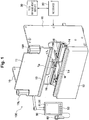
- an NC device 20 that functions as a press brake control device is connected to a press brake 100.
- a tool management server 30 is connected to the NC device 20.
- the tool management server 30 may be installed at a location away from the NC device 20 via a network.
- the tool management server 30 may be configured external to the press brake 100.
- the press brake 100 includes left and right side frames 10, an upper table 11, and a lower table 12.
- a punch holder 13 is attached to the upper table 11, and a die holder 14 is attached to the lower table 12.
- the punch holder 13 and the die holder 14 are tool holders.
- the upper table 11 is configured to move up and down by hydraulic cylinders 15L and 15R provided on the left and the right, respectively.
- a punch Tp is mounted in the punch holder 13, and a die Td is mounted in the die holder 14.
- Figure 1 shows a modular type in which the punch holder 13 is integrally attached over the entire length of a lower end portion of the upper table 11.
- the punch holder 13 may be an intermediate plate type in which a plurality of intermediate plates in which the punch Tp is mounted are attached in a longitudinal direction of the lower end portion of the upper table 11.
- Mounting the punch Tp to the upper table 11 means mounting the punch Tp in the punch holder 13 (including the case in which the punch holder 13 is an intermediate plate) .
- Mounting the die Td to the lower table 12 means mounting the die Td in the die holder 14.
- a back gauge 16 is provided behind the upper table 11 and the lower table 12.
- the back gauge 16 includes abutting members 17L and 17R that move in a lateral direction along a stretch 18.
- the abutting members 17L and 17R are configured to move also in a height direction and a longitudinal direction.
- the abutting members 17L and 17R move to positions corresponding to the die Td.
- the operator disposes the sheet metal W on the die Td such that the edge portions on the inner side of the sheet metal W abut against the abutting members 17L and 17R, respectively. That is, the abutting members 17L and 17R serve to determine the position of the sheet metal W in a longitudinal direction at a time when the sheet metal W is disposed on the die Td.
- An operation pendant 50 having a display unit 51, a touch panel 52 mounted on a surface side of the display unit 51, and an operation unit 53 including a plurality of operation buttons is connected to the NC device 20.
- the touch panel 52 also functions as the operation unit.
- An operation input from the touch panel 52 or the operation unit 53 is supplied to the NC device 20.
- a two-dimensional code reader 60 that is a reader for reading a two-dimensional code provided to the punch Tp and the die Td, which will be described later, is connected to the operation pendant 50.
- the two-dimensional code represents a tool ID (tool identification information) for individually identifying the tool.
- a barcode reader may be connected to the operation pendant 50.
- an IC tag RF tag
- a reader that reads the IC tag may be connected to the operation pendant 50.
- the operator disposes the sheet metal W to be processed on the die Td as shown in Figure 1 .
- the sheet metal W is bent by being sandwiched between the punch Tp and the die Td.
- FIG. 2 shows a specific configuration of the NC device 20 that is a press brake control device of a first embodiment.
- the NC device 20 includes a spring back amount calculation unit 201, a stroke calculation unit 202, and a bending load calculation unit 203.
- the NC device 20 includes a side frame deflection amount calculation unit 204, an upper and lower table deflection amount calculation unit 205, a punch deflection amount calculation unit 206, a punch holder deflection amount calculation unit 207, a die deflection amount calculation unit 208, and a die holder deflection amount calculation unit 209.
- the NC device 20 includes a depth value calculation unit 210 and a slide control unit 211.
- the depth value calculation unit 210 is referred to as the D value calculation unit 210
- the depth value is referred to as the D value.
- the spring back amount calculation unit 201 calculates a spring back amount based on the plasticity theory calculation.
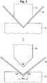
- the spring back amount calculation unit 201 uses, as the tool conditions, an angle Rp1 of the tip of the punch Tp, an angle Rd1 of both shoulder parts of a V-shaped groove of the die Td, and a width Vw1 of the V-shaped groove thereof (hereinafter referred to as a V width Vw1) shown in Figure 3 .
- the spring back amount calculation unit 201 supplies the calculated spring back amount to the stroke calculation unit 202.
- the tool conditions and the bending angle are input to the stroke calculation unit 202.
- the operator may operate the operation unit 53 to set the bending angle.
- the stroke calculation unit 202 calculates, in consideration of the spring back amount, a stroke St for bending the sheet metal W at a desired bending angle.
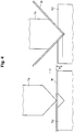
- the stroke St is a moving distance of the punch Tp at a time when the punch Tp is lowered toward the die Td to the lowest position from a state in which the tip of the punch Tp is in contact with the sheet metal W.
- the stroke calculation unit 202 supplies the calculated stroke St to the D value calculation unit 210.
- the tool conditions, the material conditions, and the bending angle are input to the bending load calculation unit 203.
- the bending load calculation unit 203 calculates, based on the plasticity theory calculation, a bending load BF required to bend the sheet metal W at a desired bending angle.
- the bending load BF is a bending load per unit length.
- the bending load calculation unit 203 supplies the calculated bending load BF to the side frame deflection amount calculation unit 204, the upper and lower table deflection amount calculation unit 205, the punch deflection amount calculation unit 206, the punch holder deflection amount calculation unit 207, the die deflection amount calculation unit 208, the die holder deflection amount calculation unit 209, and the slide control unit 211.
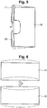
- the side frame 10 deflect such that the distance between the upper table 11 and the lower table 12 is widened.
- the deflection amount of the side frame 10 is proportional to the bending load BF.
- the side frame deflection amount calculation unit 204 calculates the side frame deflection amount d204 by a known method.
- the side frame deflection amount d204 is supplied to the D value calculation unit 210.
- the upper table 11 and the lower table 12 deflect such that the gap between the two is widened as they approach the center in a lateral direction.
- the deflection amount of the upper table 11 and the lower table 12 is proportional to the bending load BF and a bending length.
- the upper and lower table deflection amount calculation unit 205 calculates the table deflection amount d205 by a known method.
- the table deflection amount d205 is supplied to the D value calculation unit 210.
- the lower table 12 may include a crowning mechanism that pushes up the lower table 12 toward the upper table 11. In this case, it is not necessary to calculate the table deflection amount d205.
- the punch deflection amount calculation unit 206 calculates a deflection amount of the punch Tp according to the bending load.
- the deflection amount of the punch Tp varies depending on the shape of the punch Tp.
- Figure 7A shows a standard punch TpA that is a punch Tp having a standard shape.
- Figure 7B shows a gooseneck punch TpB that is a punch Tp referred to as a gooseneck.
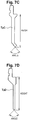
- Figure 7C shows a sash punch TpC that is a punch Tp for a sash.
- Figure 7D shows a straight sword punch TpD that is a punch Tp referred to as a straight sword.
- the height and the angle of each punch Tp are the height and the angle of the parts each shown in Figures 7A to 7D .
- Figure 8 shows the relations between the bending load and the deflection amount with respect to the standard punch TpA, the gooseneck punch TpB, the sash punch TpC, and the straight sword punch TpD, respectively. Since the pressure resistance is different among the standard punch TpA, the gooseneck punch TpB, the sash punch TpC, and the straight sword punch TpD, the maximum bending load among them is different.
- the relation between the bending load and the deflection amount for each punch Tp may be obtained by actual measurement, or may be obtained by using the FEM (finite element method) analysis.
- k is a slope of each characteristic shown in Figure 8
- k is referred to as a deflection coefficient k.
- BF is a bending load per unit length as described above, and the same applies to calculation formulae described later.
- the punch deflection amount calculation unit 206 includes a deflection coefficient holding unit 2061 and a multiplication unit 2062.
- the deflection coefficient holding unit 2061 holds, as the deflection coefficients k, a standard deflection coefficient for the standard punch TpA, a gooseneck deflection coefficient for the gooseneck punch TpB, a sash deflection coefficient for the sash punch TpC, a straight sword deflection coefficient for the straight sword punch TpD, and deflection coefficients for a plurality of other punches.
- the other punches include, for example, a punch of a special type.
- the punch deflection amount calculation unit 206 reads out, from the deflection coefficient holding unit 2061, the deflection coefficient k of the punch Tp that is being used according to the input tool condition, and supplies the readout coefficient k to the multiplication unit 2062.
- the bending load BF is input to the multiplication unit 2062.
- the multiplication unit 2062 multiplies the bending load BF by the input deflection coefficient k to calculate the punch deflection amount d206.
- the punch deflection amount d206 is supplied to the D value calculation unit 210.
- the punch holder deflection amount calculation unit 207 calculates a deflection amount of the punch holder 13 according to the bending load.
- Figure 10 shows the relation between the bending load and the deflection amount with respect to the punch holder 13.
- the deflection coefficient k is a slope of the characteristic shown in Figure 10 .
- the deflection coefficient k varies depending on whether the punch holder 13 is a modular type or an intermediate plate type.
- the deflection coefficient k also varies depending on whether the punch holder 13 is a hydraulic intermediate plate or a mechanical intermediate plate. In general, since the hydraulic intermediate plate tends to deflect less than the mechanical intermediate plate, the deflection coefficient k of the former one is smaller than that of the latter one.
- the punch holder deflection amount calculation unit 207 includes a deflection coefficient holding unit that holds the deflection coefficients k of various types of the punch holders 13 and a multiplication unit that multiplies the bending load BF by the deflection coefficient k of the punch holder 13 that is selected based on the punch holder conditions to calculate the punch holder deflection amount d207.
- the punch holder deflection amount d207 is supplied to the D value calculation unit 210.
- the punch holder deflection amount calculation unit 207 may hold a deflection coefficient k of that one type of the punch holder 13 to calculate the punch holder deflection amount d207. In this case, it is not necessary to supply the punch holder conditions to the punch holder deflection amount calculation unit 207.
- the die deflection amount calculation unit 208 calculates a deflection amount of the die Td according to the bending load.
- Figure 11 shows the relation between the bending load and the deflection amount with respect to the die Td.
- the deflection coefficient k is a slope of the characteristic shown in Figure 11 .
- the die deflection amount calculation unit 208 includes a deflection coefficient holding unit that holds the deflection coefficients k of various types of the dies Td and a multiplication unit that multiplies the bending load BF by the deflection coefficient k of the selected die Td to calculate the die deflection amount d208.
- the die deflection amount d208 is supplied to the D value calculation unit 210.
- the die holder deflection amount calculation unit 209 calculates a deflection amount of the die holder 14 according to the bending load.
- Figure 12 shows the relation between the bending load and the deflection amount with respect to the die holder 14.
- the deflection coefficient k is a slope of the characteristic shown in Figure 12 .
- the deflection coefficient k varies depending on the type of the die holder 14.
- the die holder deflection amount calculation unit 209 includes a deflection coefficient holding unit that holds the deflection coefficients k of various types of the die holders 14 and a multiplication unit that multiplies the bending load BF by the deflection coefficient k of the die holder 14 that is selected based on the die holder conditions.
- the die holder deflection amount d209 is supplied to the D value calculation unit 210.
- the die holder deflection amount calculation unit 209 may hold a deflection coefficient k of that one type of the die holder 14 to calculate the die holder deflection amount d209. In this case, it is not necessary to supply the die holder conditions to the die holder deflection amount calculation unit 209.
- the D value calculation unit 210 calculates a D value D210, which is an actual distance for which the punch Tp is lowered, by adding the side frame deflection amount d204, the table deflection amount d205, the punch deflection amount d206, the punch holder deflection amount d207, the die deflection amount d208, and the die holder deflection amount d209 to the stroke St.
- the slide control unit 211 controls the hydraulic cylinders 15L and 15R such that the bending load BF is applied to between the punch Tp and the die Td to lower the upper table 11 (punch Tp) by a distance indicated by the D value D210 and the sheet metal W is bent.
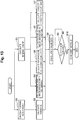
- the NC device 20 calculates a spring back amount in Step S1, and calculates a stroke St in Step S2. In parallel with Step S1, the NC device 20 calculates a bending load BF in Step S3.
- the NC device 20 calculates a punch deflection amount d206 according to the tool conditions in Step S4, and calculates a punch holder deflection amount d207 in Step S5.
- the NC device 20 calculates a die deflection amount d208 according to the tool conditions in Step S6, and calculates a die holder deflection amount d209 in Step S7.
- the NC device 20 calculate a D value D210 by adding the respective deflection amounts to the stroke St.
- Step S9 the NC device 20 determines whether or not a start of bending of the sheet metal W is instructed. If there is no instruction to start work (NO), the NC device 20 repeats the process of Step S9. If there is an instruction to start work (YES), the NC device 20 bends the sheet metal W by lowering the upper table 11 by a distance indicated by the D value D210 in Step S10, and ends the processing.
- the bending accuracy of the sheet metal W can be further improved. It is not necessary to make it mandatory that the press brake control device of the first embodiment is provided with all of the side frame deflection amount calculation unit 204, the upper and lower table deflection amount calculation unit 205, the punch deflection amount calculation unit 206, the punch holder deflection amount calculation unit 207, the die deflection amount calculation unit 208, and the die holder deflection amount calculation unit 209.
- the die deflection amount d208 is smaller than the punch deflection amount d206, and the die holder deflection amount d209 is smaller than the punch holder deflection amount d207.
- the die holder deflection amount d209 is smaller than the die deflection amount d208. Therefore, the bending accuracy of the sheet metal W can be improved even if the NC device 20 is provided only with the punch deflection amount calculation unit 206 and the punch holder deflection amount calculation unit 207.
- the NC device 20 may be provided at least with the punch deflection amount calculation unit 206 and the punch holder deflection amount calculation unit 207.
- the NC device 20 is provided with the die deflection amount calculation unit 208 in addition to the punch deflection amount calculation unit 206 and the punch holder deflection amount calculation unit 207. It is further preferable that the NC device 20 is provided with the die deflection amount calculation unit 208 and the die holder deflection amount calculation unit 209 in addition to the punch deflection amount calculation unit 206 and the punch holder deflection amount calculation unit 207.
- the NC device 20 may be provided with the punch deflection amount calculation unit 206 and the punch holder deflection amount calculation unit 207 in addition to the side frame deflection amount calculation unit 204 and the upper and lower table deflection amount calculation unit 205.
- the NC device 20 may be provided with the punch deflection amount calculation unit 206, the punch holder deflection amount calculation unit 207, and the die deflection amount calculation unit 208 in addition to the side frame deflection amount calculation unit 204 and the upper and lower table deflection amount calculation unit 205.
- the upper and lower table deflection amount calculation unit 205 may be omitted.
- Figure 14 shows a state in which the punch holder 13 holds the gooseneck punch TpB as an example.
- the punch holder 13 is an intermediate plate.
- a clamper 131 of the punch holder 13 clamps an upper end portion of the gooseneck punch TpB.
- Verification by the present inventor has revealed that the punch deflection amount d206 varies depending on the constraint conditions on which the punch holder 13 holds the punch Tp.
- the constraint conditions include a gripping force by the clamper 131 and a gripping position at which the clamper 131 clamps the punch Tp.
- the punch deflection amount d206 also varies depending on a friction coefficient between the punch holder 13 and the punch Tp.
- the punch deflection amount d206 is calculated in an exact manner according to the type of the punch holder 13 that holds the punch Tp.
- the relation between the bending load and the deflection amount with respect to the punch Tp in a state in which the punch holder 13 is holding the punch Tp may be obtained by actual measurement or by using the FEM analysis.
- the punch deflection amount d206 of the punch Tp alone is calculated.
- the punch deflection amount d206 is calculated according to the type of the punch holder 13 that holds the punch Tp.
- the deflection coefficient holding unit 2061 holds a set of the standard deflection coefficient, the gooseneck deflection coefficient, the sash deflection coefficient, the straight sword deflection coefficient, and the deflection coefficients for the plurality of other punches corresponding to the types of the punch holders 13.
- a punch holder No. 1 is one type of the punch holders 13
- a punch holder No. 2 is another one type of the punch holders 13.
- the deflection coefficient holding unit 2061 may hold a set of deflection coefficients corresponding to the types of the punch holders 13 that the press brake 100 may use.
- the punch deflection amount calculation unit 206 reads out, from the deflection coefficient holding unit 2061, the deflection coefficient k of the punch Tp, which is being used from among the set of deflection coefficients corresponding to the types of the punch holders 13, according to the input punch holder conditions and tool conditions, and supplies the read-out deflection coefficient k to the multiplication unit 2062. This enables the punch deflection amount calculation unit 206 to calculate a more exact punch deflection amount d206 according to the type of the punch holder 13 that holds the punch Tp.
- the die deflection amount calculation unit 208 can also calculate a more exact die deflection amount d208 according to the type of the die holder 14 that holds the die Td.
- Step S4 of Figure 13 it is only necessary in Step S4 of Figure 13 to calculate the punch deflection amount d206 according to the punch holder conditions and the tool conditions, and in Step S6 thereof to calculate the die deflection amount d208 according to the die holder conditions and the tool conditions.
- the bending accuracy of the sheet metal W can be further improved as compared to the first embodiment.
- the NC device 20 that is a press brake control device of the third embodiment includes a tool information reading unit 212.
- illustrations of the side frame deflection amount calculation unit 204 and the upper and lower table deflection amount calculation unit 205 are omitted.
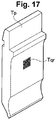
- a two-dimensional code Tqr representing a tool ID is provided to each tool by, for example, laser marking.
- Figure 17 illustrates a punch Tp on which a two-dimensional code Tqr is formed.
- Figure 17 illustrates a state in which the two-dimensional code Tqr is marked on a back surface of the punch Tp.
- the two-dimensional code Tqr may be marked on a front surface or both surfaces of the tool.
- the operator reads out the two-dimensional code Tqr with a two-dimensional code reader 60 when the tool is mounted in the punch holder 13 or the die holder 14.
- the tool ID indicated by the read-out two-dimensional code Tqr is supplied to the tool information reading unit 212.
- tool information including a tool type indicating whether the tool is a punch Tp or a die Td, a model number, a shape, an angle, a height, a pressure resistance, a deflection coefficient k, and other information is expressed by a predetermined number of digits (number of bits).
- the tool information may include necessary information depending on whether the tool is a punch Tp or a die Td.
- the deflection coefficient k is a deflection coefficient k of the punch Tp or the die Td. In the tool information, which bit indicates which information is determined in advance.
- the tool used for bending the sheet metal W in the third embodiment is provided with the tool ID.
- the tool ID indicates tool information including various types of information on the tool.
- the tool information includes a deflection coefficient k for calculating a deflection amount of the tool (the punch deflection amount d206 or the die deflection amount d208) according to a predetermined bending load BF that is applied to the sheet metal W at a time when the sheet metal W is bent.
- a data structure of the tool information shown in Figure 18 is referred to by the NC device 20 that controls the press brake 100 for bending the sheet metal W by using the tool.
- the data structure of the tool information includes the deflection coefficient k referred to by the NC device 20 when the NC device 20 calculates a deflection amount of the tool according to a predetermined bending load BF that is applied to the sheet metal W at a time when the sheet metal W is bent.
- the tool information reading unit 212 extracts information necessary for calculating a spring back amount from the input tool ID and supplies the extracted information to the spring back amount calculation unit 201.
- the tool information reading unit 212 supplies the tool conditions that are based on the tool ID to the bending load calculation unit 203.
- the tool information reading unit 212 extracts the deflection coefficient k of the punch Tp so as to supply it to the punch deflection amount calculation unit 206, and extracts the deflection coefficient k of the die Td so as to supply it to the die deflection amount calculation unit 208.
- the NC device 20 can obtain a tool-specific deflection coefficient k by way of the tool ID provided to the tool, it is not necessary for the punch deflection amount calculation unit 206 and the die deflection amount calculation unit 208 to hold a plurality of deflection coefficients k according to the types of the tools. Therefore, according to the third embodiment, the configuration of the NC device 20 or the processing executed by the NC device 20 can be simplified.
- the punch deflection amount d206 or the die deflection amount d208 is each calculated according to the type of the punch holder 13 that holds the punch Tp or the die holder 14 that holds the die Td.
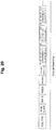
- Figure 20 shows tool information indicated by a tool ID provided to the tool that is used in the fourth embodiment, for example, in the case in which the tool is a punch Tp.
- the tool information includes deflection coefficients k corresponding to the types of the punch holders 13.
- the deflection coefficients k corresponding to three types of the punch holders 13, i.e., punch holders No. 1 to No. 3, are included.
- the tool ID provided to the tool that is used in the fourth embodiment indicates tool information including a plurality of deflection coefficients k corresponding to the types of the tool holders for calculating the deflection amount of the tool according to the type of the tool holder that holds the tool.
- the data structure of the tool information shown in Figure 20 includes the plurality of deflection coefficients k according to the types of the tool holders that are referred to by the NC device 20 when the NC device 20 calculates the deflection amount of the tool corresponding to the type of the tool holder that holds the tool.
- the tool information reading unit 212 extracts a plurality of deflection coefficients k of the punches Tp corresponding to the types of the punch holders 13 from the input tool ID, and supplies the extracted deflection coefficients k to the punch deflection amount calculation unit 206.
- the tool information reading unit 212 extracts a plurality of deflection coefficients k of the die Td corresponding to the type of the die holder 14 from the input tool ID, and supplies the extracted deflection coefficients k to the die deflection amount calculation unit 208.
- the punch holder conditions, which indicate the punch holder 13 that is being used, are input to the punch deflection amount calculation unit 206, and the die holder conditions, which indicate the die holder 14 that is being used, are input to the die deflection amount calculation unit 208.
- the punch deflection amount calculation unit 206 selects the deflection coefficient k of the punch Tp corresponding to the punch holder 13 that is being used, and calculates the punch deflection amount d206.
- the die deflection amount calculation unit 208 selects the deflection coefficient k of the die Td corresponding to the die holder 14 that is being used, and calculates the die deflection amount d208.
- the present invention is not limited to the first to fourth embodiments described above, and various modifications can be made without departing from the scope of the present invention.
- configuring the press brake control device of each embodiment whether to use software or hardware is arbitrary.
- the present invention is not limited to a configuration shown in Figures 2 , 16 , and 19 , in which the configuration of the NC device 20 is realized by software.
- the NC device 20 holds the deflection coefficient k and calculates each deflection amount.
- the NC device 20 may be configured to have the deflection coefficient k stored in a storage device external to the NC device 20, and to read the deflection coefficient k from the storage device.
- Figure 1 illustrates the lowering type press brake 100 in which the upper table 11 is lowered toward the lower table 12.
- An elevating type press brake in which the lower table 12 is elevated toward the upper table 11 may be used.
Landscapes
- Engineering & Computer Science (AREA)
- Mechanical Engineering (AREA)
- Human Computer Interaction (AREA)
- Manufacturing & Machinery (AREA)
- Physics & Mathematics (AREA)
- General Physics & Mathematics (AREA)
- Automation & Control Theory (AREA)
- Bending Of Plates, Rods, And Pipes (AREA)
Abstract
Description
- The present disclosure relates to a press brake control device, a press brake control method, a tool, and a data structure of tool information.
- A press brake for bending a sheet metal includes an upper table on which a punch is mounted and a lower table on which a die is mounted. The press brake bends the sheet metal by lowering the upper table toward the lower table and then sandwiching the sheet metal disposed on the die between the punch and the die.
- A distance (stroke) by which the punch is lowered toward the die from a state in which the tip of the punch is in contact with the sheet metal is determined by a desired bending angle of the sheet metal. However, in practice, due to the existence of deflection of side frames of the press brake as well as deflection of the upper table and the lower table, it is not possible to bend the sheet metal at a desired bending angle even if the punch is lowered by a calculated stroke.
-
Patent Literature 1 describes that a sheet metal is bent by obtaining a depth value (D value), which is a distance in which a stroke is corrected in consideration of deflection of the side frames and deflection of the upper table and the lower table, and then lowering the punch by the D value. Furthermore,Patent Literature 1 describes that a bending accuracy is improved by correcting the D value in consideration of deflection of the punch and then lowering the punch by the corrected D value to bend the sheet metal. - Patent Literature 1: Japanese Patent Laid-Open No.
9-192746 - Though the bending accuracy is improved by using the corrected D value described in
Patent Literature 1, it is not possible to bend the sheet metal at a desired bending angle thereby. Hence, there has been a demand for further improvement of the bending accuracy. - An object of embodiments is to provide a press brake control device, a press brake control method, a tool, and a data structure of tool information that can further improve the bending accuracy of a sheet metal.
- According to a first aspect of the embodiment, there is provided a press brake control device including a stroke calculation unit configured to calculate, when a sheet metal is sandwiched between a punch held by a punch holder and a die held by a die holder and the punch is moved toward the die to bend the sheet metal at a set bending angle, a stroke of the punch for bending the sheet metal at the bending angle in consideration of a spring back amount of the bent sheet metal, a bending load calculation unit configured to calculate a bending load required to bend the sheet metal at the bending angle, a punch deflection amount calculation unit configured to calculate a punch deflection amount that is a deflection amount of the punch according to the bending load, a punch holder deflection amount calculation unit configured to calculate a punch holder deflection amount that is a deflection amount of the punch holder according to the bending load; and a depth value calculation unit configured to calculate a depth value by adding at least the punch deflection amount and the punch holder deflection amount to the stroke, the depth value being a distance by which the punch is moved toward the die.
- According to a second aspect of the embodiment, there is provided a press brake control method, executed by a control device that controls a press brake for bending a sheet metal by sandwiching the sheet metal between a punch held by a punch holder and a die held by a die holder and then moving the punch toward the die, the press brake control method including calculating a stroke of the punch for bending the sheet metal at a set bending angle in consideration of a spring back amount of the bent sheet metal, calculating a bending load required to bend the sheet metal at the bending angle, calculating a punch deflection amount that is a deflection amount of the punch according to the bending load, calculating a punch holder deflection amount that is a deflection amount of the punch holder according to the bending load, calculating a depth value by adding at least the punch deflection amount and the punch holder deflection amount to the stroke, the depth value being a distance by which the punch is moved toward the die, and controlling such that the punch is moved by the depth value to bend the metal sheet.
- According to a third aspect of the embodiment, there is provided a tool used for bending a sheet metal, the tool including a tool ID that indicates tool information including a deflection coefficient for calculating a deflection amount of the tool according to a predetermined bending load applied to the sheet metal at a time when the sheet metal is bent.
- According to a fourth aspect of the embodiment, there is provided a data structure of tool information referred to by a control device that controls a press brake for bending a sheet metal by using a tool, the data structure including a deflection coefficient referred to by the control device when the control device calculates a deflection amount of the tool according to a predetermined bending load applied to the sheet metal at a time when the sheet metal is bent.
- With the press brake control device, the press brake control method, the tool, and the data structure of the tool information of the embodiment, the bending accuracy of the sheet metal can be further improved.
-
- [
Figure 1] Figure 1 is a diagram showing an example of an entire configuration of a press brake of each embodiment. - [
Figure 2] Figure 2 is a block diagram showing a press brake control device of a first embodiment. - [
Figure 3] Figure 3 is a view for explaining spring back of a bent sheet metal. - [
Figure 4] Figure 4 is a view showing a stroke of a punch at a time when a sheet metal is bent by being sandwiched between a punch and a die. - [
Figure 5] Figure 5 is a conceptual diagram showing deflection of a side frame. - [
Figure 6] Figure 6 is a conceptual diagram showing deflection of an upper table and a lower table. - [
Figure 7A] Figure 7A is a side view showing a standard punch. - [
Figure 7B] Figure 7B is a side view showing a gooseneck punch. - [
Figure 7C] Figure 7C is a side view showing a sash punch. - [
Figure 7D] Figure 7D is a side view showing a straight sword punch. - [
Figure 8] Figure 8 is a characteristic diagram showing the relations between a bending load and a deflection amount with respect to the standard punch, the gooseneck punch, the sash punch, and the straight sword punch, respectively. - [
Figure 9] Figure 9 is a block diagram showing a configuration example of a punch deflection amount calculation unit provided to a press brake control device of a first embodiment. - [
Figure 10] Figure 10 is a characteristic diagram showing the relation between the bending load and the deflection amount with respect to a punch holder. - [
Figure 11] Figure 11 is a characteristic diagram showing the relation between the bending load and the deflection amount with respect to a die. - [
Figure 12] Figure 12 is a characteristic diagram showing the relation between the bending load and the deflection amount with respect to a die holder. - [
Figure 13] Figure 13 is a flowchart showing processing of a press brake control method of the first embodiment. - [
Figure 14] Figure 14 is a side view showing a state in which the punch holder holds the gooseneck punch. - [
Figure 15] Figure 15 is a block diagram showing a configuration example of a punch deflection amount calculation unit provided to a press brake control device of a second embodiment. - [
Figure 16] Figure 16 is a block diagram showing a press brake control device of a third embodiment. - [
Figure 17] Figure 17 is a perspective view showing an example of a tool having a tool ID. - [
Figure 18] Figure 18 is a diagram showing an example of a data structure of tool information referred to by the press brake control device of the third embodiment. - [
Figure 19] Figure 19 is a block diagram showing a press brake control device of a fourth embodiment. - [
Figure 20] Figure 20 is a diagram showing an example of a data structure of tool information referred to by a press brake control device of a fourth embodiment. - Hereinafter, the press brake control device, the press brake control method, the tool, and the data structure of the tool information of each embodiment will be described with reference to the accompanying drawings.
- First, a schematic configuration and operation of a press brake that is common to each embodiment will be described. As shown in
Figure 1 , anNC device 20 that functions as a press brake control device is connected to apress brake 100. Atool management server 30 is connected to theNC device 20. Thetool management server 30 may be installed at a location away from theNC device 20 via a network. Thetool management server 30 may be configured external to thepress brake 100. - The
press brake 100 includes left andright side frames 10, an upper table 11, and a lower table 12. Apunch holder 13 is attached to the upper table 11, and adie holder 14 is attached to the lower table 12. Thepunch holder 13 and the dieholder 14 are tool holders. The upper table 11 is configured to move up and down byhydraulic cylinders punch holder 13, and a die Td is mounted in the dieholder 14. -
Figure 1 shows a modular type in which thepunch holder 13 is integrally attached over the entire length of a lower end portion of the upper table 11. Thepunch holder 13 may be an intermediate plate type in which a plurality of intermediate plates in which the punch Tp is mounted are attached in a longitudinal direction of the lower end portion of the upper table 11. - Mounting the punch Tp to the upper table 11 means mounting the punch Tp in the punch holder 13 (including the case in which the
punch holder 13 is an intermediate plate) . Mounting the die Td to the lower table 12 means mounting the die Td in the dieholder 14. - A
back gauge 16 is provided behind the upper table 11 and the lower table 12. Theback gauge 16 includes abuttingmembers 17L and 17R that move in a lateral direction along astretch 18. The abuttingmembers 17L and 17R are configured to move also in a height direction and a longitudinal direction. - Before an operator disposes a sheet metal W on the die Td and bends the sheet metal W, the
abutting members 17L and 17R move to positions corresponding to the die Td. The operator disposes the sheet metal W on the die Td such that the edge portions on the inner side of the sheet metal W abut against the abuttingmembers 17L and 17R, respectively. That is, the abuttingmembers 17L and 17R serve to determine the position of the sheet metal W in a longitudinal direction at a time when the sheet metal W is disposed on the die Td. - An
operation pendant 50 having a display unit 51, a touch panel 52 mounted on a surface side of the display unit 51, and anoperation unit 53 including a plurality of operation buttons is connected to theNC device 20. The touch panel 52 also functions as the operation unit. An operation input from the touch panel 52 or theoperation unit 53 is supplied to theNC device 20. - A two-
dimensional code reader 60 that is a reader for reading a two-dimensional code provided to the punch Tp and the die Td, which will be described later, is connected to theoperation pendant 50. The two-dimensional code represents a tool ID (tool identification information) for individually identifying the tool. When a barcode is used instead of the two-dimensional code, a barcode reader may be connected to theoperation pendant 50. When an IC tag (RF tag) is used instead of the two-dimensional code, a reader that reads the IC tag may be connected to theoperation pendant 50. - In the
press brake 100 configured as described above, the operator disposes the sheet metal W to be processed on the die Td as shown inFigure 1 . When the operator lowers the upper table 11, the sheet metal W is bent by being sandwiched between the punch Tp and the die Td. -
Figure 2 shows a specific configuration of theNC device 20 that is a press brake control device of a first embodiment. TheNC device 20 includes a spring backamount calculation unit 201, astroke calculation unit 202, and a bendingload calculation unit 203. TheNC device 20 includes a side frame deflectionamount calculation unit 204, an upper and lower table deflectionamount calculation unit 205, a punch deflectionamount calculation unit 206, a punch holder deflectionamount calculation unit 207, a die deflectionamount calculation unit 208, and a die holder deflectionamount calculation unit 209. TheNC device 20 includes a depthvalue calculation unit 210 and aslide control unit 211. Hereinafter, the depthvalue calculation unit 210 is referred to as the Dvalue calculation unit 210, and the depth value is referred to as the D value. - As shown in
Figure 3 , when the punch Tp is elevated after the sheet metal W is bent by being sandwiched between the punch Tp and the die Td, the bent sheet metal W tries to return to the original flat state, which makes the bending angle larger. This phenomenon is called spring back. Material conditions including at least a material and a thickness of the sheet metal W as well as tool conditions of the punch Tp and the die Td are input to the spring backamount calculation unit 201. The operator may operate theoperation unit 53 to set the material conditions. TheNC device 20 reads out the tool conditions of the tool to be used from thetool management server 30. - By using the material conditions and the tool conditions, the spring back
amount calculation unit 201 calculates a spring back amount based on the plasticity theory calculation. - In order to calculate the spring back amount, the spring back
amount calculation unit 201 uses, as the tool conditions, an angle Rp1 of the tip of the punch Tp, an angle Rd1 of both shoulder parts of a V-shaped groove of the die Td, and a width Vw1 of the V-shaped groove thereof (hereinafter referred to as a V width Vw1) shown inFigure 3 . The spring backamount calculation unit 201 supplies the calculated spring back amount to thestroke calculation unit 202. - The tool conditions and the bending angle are input to the
stroke calculation unit 202. The operator may operate theoperation unit 53 to set the bending angle. Based on the plasticity theory calculation, thestroke calculation unit 202 calculates, in consideration of the spring back amount, a stroke St for bending the sheet metal W at a desired bending angle. As shown inFigure 4 , the stroke St is a moving distance of the punch Tp at a time when the punch Tp is lowered toward the die Td to the lowest position from a state in which the tip of the punch Tp is in contact with the sheet metal W. Thestroke calculation unit 202 supplies the calculated stroke St to the Dvalue calculation unit 210. - The tool conditions, the material conditions, and the bending angle are input to the bending
load calculation unit 203. By using the tool conditions, the material conditions, and the bending angle, the bendingload calculation unit 203 calculates, based on the plasticity theory calculation, a bending load BF required to bend the sheet metal W at a desired bending angle. The bending load BF is a bending load per unit length. The bendingload calculation unit 203 supplies the calculated bending load BF to the side frame deflectionamount calculation unit 204, the upper and lower table deflectionamount calculation unit 205, the punch deflectionamount calculation unit 206, the punch holder deflectionamount calculation unit 207, the die deflectionamount calculation unit 208, the die holder deflectionamount calculation unit 209, and theslide control unit 211. - As conceptually shown in
Figure 5 , when a force F is applied between the upper table 11 and the lower table 12, theside frame 10 deflect such that the distance between the upper table 11 and the lower table 12 is widened. The deflection amount of theside frame 10 is proportional to the bending load BF. When the deflection amount of theside frame 10 is defined as a side frame deflection amount d204, the side frame deflectionamount calculation unit 204 calculates the side frame deflection amount d204 by a known method. The side frame deflection amount d204 is supplied to the Dvalue calculation unit 210. - As conceptually shown in
Figure 6 , when a force F is applied between the upper table 11 and the lower table 12, the upper table 11 and the lower table 12 deflect such that the gap between the two is widened as they approach the center in a lateral direction. The deflection amount of the upper table 11 and the lower table 12 is proportional to the bending load BF and a bending length. When the deflection amount of the upper table 11 and the lower table 12 is defined as a table deflection amount d205, the upper and lower table deflectionamount calculation unit 205 calculates the table deflection amount d205 by a known method. The table deflection amount d205 is supplied to the Dvalue calculation unit 210. - The lower table 12 may include a crowning mechanism that pushes up the lower table 12 toward the upper table 11. In this case, it is not necessary to calculate the table deflection amount d205.
- The punch deflection
amount calculation unit 206 calculates a deflection amount of the punch Tp according to the bending load. The deflection amount of the punch Tp varies depending on the shape of the punch Tp.Figure 7A shows a standard punch TpA that is a punch Tp having a standard shape.Figure 7B shows a gooseneck punch TpB that is a punch Tp referred to as a gooseneck.Figure 7C shows a sash punch TpC that is a punch Tp for a sash.Figure 7D shows a straight sword punch TpD that is a punch Tp referred to as a straight sword. The height and the angle of each punch Tp are the height and the angle of the parts each shown inFigures 7A to 7D . -
Figure 8 shows the relations between the bending load and the deflection amount with respect to the standard punch TpA, the gooseneck punch TpB, the sash punch TpC, and the straight sword punch TpD, respectively. Since the pressure resistance is different among the standard punch TpA, the gooseneck punch TpB, the sash punch TpC, and the straight sword punch TpD, the maximum bending load among them is different. The relation between the bending load and the deflection amount for each punch Tp may be obtained by actual measurement, or may be obtained by using the FEM (finite element method) analysis. - It has been confirmed through the verification by the present inventor that the relation between the bending load and the deflection amount with respect to each punch Tp obtained by using the FEM analysis is almost the same as that obtained by actual measurement. Similarly, regarding the relation between the bending load and the deflection amount with respect to the
punch holder 13, the relation between the bending load and the deflection amount with respect to the die Td, and the relation between the bending load and the deflection amount with respect to thedie holder 14, which will be described later, it has been confirmed that there is almost no difference between the ones obtained by using the FEM analysis and the ones obtained by actual measurement. Therefore, either actual measurement or the FEM analysis may be used. - When the deflection amount of the punch Tp is defined as a punch deflection amount d206, the punch deflection amount d206 can be obtained by a calculation formula of d206 = k × BF. In the calculation formula, k is a slope of each characteristic shown in
Figure 8 , and k is referred to as a deflection coefficient k. In the calculation formula, BF is a bending load per unit length as described above, and the same applies to calculation formulae described later. - As shown in
Figure 9 , the punch deflectionamount calculation unit 206 includes a deflectioncoefficient holding unit 2061 and amultiplication unit 2062. The deflectioncoefficient holding unit 2061 holds, as the deflection coefficients k, a standard deflection coefficient for the standard punch TpA, a gooseneck deflection coefficient for the gooseneck punch TpB, a sash deflection coefficient for the sash punch TpC, a straight sword deflection coefficient for the straight sword punch TpD, and deflection coefficients for a plurality of other punches. The other punches include, for example, a punch of a special type. The punch deflectionamount calculation unit 206 reads out, from the deflectioncoefficient holding unit 2061, the deflection coefficient k of the punch Tp that is being used according to the input tool condition, and supplies the readout coefficient k to themultiplication unit 2062. - The bending load BF is input to the
multiplication unit 2062. Themultiplication unit 2062 multiplies the bending load BF by the input deflection coefficient k to calculate the punch deflection amount d206. The punch deflection amount d206 is supplied to the Dvalue calculation unit 210. - The punch holder deflection
amount calculation unit 207 calculates a deflection amount of thepunch holder 13 according to the bending load.Figure 10 shows the relation between the bending load and the deflection amount with respect to thepunch holder 13. When the deflection amount of thepunch holder 13 is defined as a punch holder deflection amount d207, the punch holder deflection amount d207 can be obtained by the calculation formula of d207 = k × BF. Here, the deflection coefficient k is a slope of the characteristic shown inFigure 10 . - Though only one characteristic of the
punch holder 13 is shown inFigure 10 , the deflection coefficient k varies depending on whether thepunch holder 13 is a modular type or an intermediate plate type. The deflection coefficient k also varies depending on whether thepunch holder 13 is a hydraulic intermediate plate or a mechanical intermediate plate. In general, since the hydraulic intermediate plate tends to deflect less than the mechanical intermediate plate, the deflection coefficient k of the former one is smaller than that of the latter one. - In a similar manner to
Figure 9 , the punch holder deflectionamount calculation unit 207 includes a deflection coefficient holding unit that holds the deflection coefficients k of various types of thepunch holders 13 and a multiplication unit that multiplies the bending load BF by the deflection coefficient k of thepunch holder 13 that is selected based on the punch holder conditions to calculate the punch holder deflection amount d207. The punch holder deflection amount d207 is supplied to the Dvalue calculation unit 210. - When the
press brake 100 uses one type of thepunch holder 13 in a fixed manner, the punch holder deflectionamount calculation unit 207 may hold a deflection coefficient k of that one type of thepunch holder 13 to calculate the punch holder deflection amount d207. In this case, it is not necessary to supply the punch holder conditions to the punch holder deflectionamount calculation unit 207. - The die deflection
amount calculation unit 208 calculates a deflection amount of the die Td according to the bending load.Figure 11 shows the relation between the bending load and the deflection amount with respect to the die Td. When the deflection amount of the die Td is defined as a die deflection amount d208, the die deflection amount d208 can be obtained by the calculation formula of d208 = k × BF. Here, the deflection coefficient k is a slope of the characteristic shown inFigure 11 . - Though only one characteristic of the die Td is shown in
Figure 11 , the deflection coefficient k varies depending on the type and the V width Vw1 of the die Td. In a similar manner toFigure 9 , the die deflectionamount calculation unit 208 includes a deflection coefficient holding unit that holds the deflection coefficients k of various types of the dies Td and a multiplication unit that multiplies the bending load BF by the deflection coefficient k of the selected die Td to calculate the die deflection amount d208. The die deflection amount d208 is supplied to the Dvalue calculation unit 210. - The die holder deflection
amount calculation unit 209 calculates a deflection amount of thedie holder 14 according to the bending load.Figure 12 shows the relation between the bending load and the deflection amount with respect to thedie holder 14. When the deflection amount of thedie holder 14 is defined as a die holder deflection amount d209, the die holder deflection amount d209 can be obtained by the calculation formula of d209 = k × BF. Here, the deflection coefficient k is a slope of the characteristic shown inFigure 12 . - Though only one characteristic of the
die holder 14 is shown inFigure 12 , the deflection coefficient k varies depending on the type of thedie holder 14. In a similar manner toFigure 9 , the die holder deflectionamount calculation unit 209 includes a deflection coefficient holding unit that holds the deflection coefficients k of various types of thedie holders 14 and a multiplication unit that multiplies the bending load BF by the deflection coefficient k of thedie holder 14 that is selected based on the die holder conditions. The die holder deflection amount d209 is supplied to the Dvalue calculation unit 210. - When the
press brake 100 uses one type of thedie holder 14 in a fixed manner, the die holder deflectionamount calculation unit 209 may hold a deflection coefficient k of that one type of thedie holder 14 to calculate the die holder deflection amount d209. In this case, it is not necessary to supply the die holder conditions to the die holder deflectionamount calculation unit 209. - Returning to
Figure 2 , the Dvalue calculation unit 210 calculates a D value D210, which is an actual distance for which the punch Tp is lowered, by adding the side frame deflection amount d204, the table deflection amount d205, the punch deflection amount d206, the punch holder deflection amount d207, the die deflection amount d208, and the die holder deflection amount d209 to the stroke St. Theslide control unit 211 controls thehydraulic cylinders - By using a flowchart shown in
Figure 13 , an operation in which theNC device 20 calculates the D value D210 that is the processing of the press brake control method of the first embodiment will be described again. InFigure 13 , for simplification, the processing by the side frame deflectionamount calculation unit 204 and the upper and lower table deflectionamount calculation unit 205 is omitted, and it is assumed that for thepunch holder 13 and thedie holder 14, one types are used in a fixed manner, respectively. - In
Figure 13 , when the processing is started, theNC device 20 calculates a spring back amount in Step S1, and calculates a stroke St in Step S2. In parallel with Step S1, theNC device 20 calculates a bending load BF in Step S3. - The
NC device 20 calculates a punch deflection amount d206 according to the tool conditions in Step S4, and calculates a punch holder deflection amount d207 in Step S5. TheNC device 20 calculates a die deflection amount d208 according to the tool conditions in Step S6, and calculates a die holder deflection amount d209 in Step S7. In Step S8, theNC device 20 calculate a D value D210 by adding the respective deflection amounts to the stroke St. - In Step S9, the
NC device 20 determines whether or not a start of bending of the sheet metal W is instructed. If there is no instruction to start work (NO), theNC device 20 repeats the process of Step S9. If there is an instruction to start work (YES), theNC device 20 bends the sheet metal W by lowering the upper table 11 by a distance indicated by the D value D210 in Step S10, and ends the processing. - According to the first embodiment, the bending accuracy of the sheet metal W can be further improved. It is not necessary to make it mandatory that the press brake control device of the first embodiment is provided with all of the side frame deflection
amount calculation unit 204, the upper and lower table deflectionamount calculation unit 205, the punch deflectionamount calculation unit 206, the punch holder deflectionamount calculation unit 207, the die deflectionamount calculation unit 208, and the die holder deflectionamount calculation unit 209. - The die deflection amount d208 is smaller than the punch deflection amount d206, and the die holder deflection amount d209 is smaller than the punch holder deflection amount d207. The die holder deflection amount d209 is smaller than the die deflection amount d208. Therefore, the bending accuracy of the sheet metal W can be improved even if the
NC device 20 is provided only with the punch deflectionamount calculation unit 206 and the punch holder deflectionamount calculation unit 207. TheNC device 20 may be provided at least with the punch deflectionamount calculation unit 206 and the punch holder deflectionamount calculation unit 207. - It is preferable that the
NC device 20 is provided with the die deflectionamount calculation unit 208 in addition to the punch deflectionamount calculation unit 206 and the punch holder deflectionamount calculation unit 207. It is further preferable that theNC device 20 is provided with the die deflectionamount calculation unit 208 and the die holder deflectionamount calculation unit 209 in addition to the punch deflectionamount calculation unit 206 and the punch holder deflectionamount calculation unit 207. - The
NC device 20 may be provided with the punch deflectionamount calculation unit 206 and the punch holder deflectionamount calculation unit 207 in addition to the side frame deflectionamount calculation unit 204 and the upper and lower table deflectionamount calculation unit 205. TheNC device 20 may be provided with the punch deflectionamount calculation unit 206, the punch holder deflectionamount calculation unit 207, and the die deflectionamount calculation unit 208 in addition to the side frame deflectionamount calculation unit 204 and the upper and lower table deflectionamount calculation unit 205. As described above, in some cases, the upper and lower table deflectionamount calculation unit 205 may be omitted. - With reference to
Figures 14 and15 , a press brake control device and a press brake control method of a second embodiment will be described. In the second embodiment, what is different from the first embodiment will be described, and description of the common part will be omitted. -
Figure 14 shows a state in which thepunch holder 13 holds the gooseneck punch TpB as an example. Here, thepunch holder 13 is an intermediate plate. Aclamper 131 of thepunch holder 13 clamps an upper end portion of the gooseneck punch TpB. Verification by the present inventor has revealed that the punch deflection amount d206 varies depending on the constraint conditions on which thepunch holder 13 holds the punch Tp. The constraint conditions include a gripping force by theclamper 131 and a gripping position at which theclamper 131 clamps the punch Tp. To be more exact, the punch deflection amount d206 also varies depending on a friction coefficient between thepunch holder 13 and the punch Tp. - Therefore, it is preferable that the punch deflection amount d206 is calculated in an exact manner according to the type of the
punch holder 13 that holds the punch Tp. The relation between the bending load and the deflection amount with respect to the punch Tp in a state in which thepunch holder 13 is holding the punch Tp may be obtained by actual measurement or by using the FEM analysis. - In the first embodiment, the punch deflection amount d206 of the punch Tp alone is calculated. In the second embodiment, the punch deflection amount d206 is calculated according to the type of the
punch holder 13 that holds the punch Tp. - As shown in
Figure 15 , the deflectioncoefficient holding unit 2061 holds a set of the standard deflection coefficient, the gooseneck deflection coefficient, the sash deflection coefficient, the straight sword deflection coefficient, and the deflection coefficients for the plurality of other punches corresponding to the types of thepunch holders 13. A punch holder No. 1 is one type of thepunch holders 13, and a punch holder No. 2 is another one type of thepunch holders 13. The deflectioncoefficient holding unit 2061 may hold a set of deflection coefficients corresponding to the types of thepunch holders 13 that thepress brake 100 may use. - The punch deflection
amount calculation unit 206 reads out, from the deflectioncoefficient holding unit 2061, the deflection coefficient k of the punch Tp, which is being used from among the set of deflection coefficients corresponding to the types of thepunch holders 13, according to the input punch holder conditions and tool conditions, and supplies the read-out deflection coefficient k to themultiplication unit 2062. This enables the punch deflectionamount calculation unit 206 to calculate a more exact punch deflection amount d206 according to the type of thepunch holder 13 that holds the punch Tp. - Similarly, the die deflection
amount calculation unit 208 can also calculate a more exact die deflection amount d208 according to the type of thedie holder 14 that holds the die Td. - In the second embodiment, it is only necessary in Step S4 of
Figure 13 to calculate the punch deflection amount d206 according to the punch holder conditions and the tool conditions, and in Step S6 thereof to calculate the die deflection amount d208 according to the die holder conditions and the tool conditions. - According to the second embodiment, the bending accuracy of the sheet metal W can be further improved as compared to the first embodiment.
- With reference to
Figures 16 to 18 , a press brake control device and a press brake control method of a third embodiment will be described. In the third embodiment, what is different from the first embodiment will be described, and description of the common part will be omitted. - As shown in
Figure 16 , theNC device 20 that is a press brake control device of the third embodiment includes a toolinformation reading unit 212. InFigure 16 , illustrations of the side frame deflectionamount calculation unit 204 and the upper and lower table deflectionamount calculation unit 205 are omitted. - As shown in
Figure 17 , a two-dimensional code Tqr representing a tool ID is provided to each tool by, for example, laser marking.Figure 17 illustrates a punch Tp on which a two-dimensional code Tqr is formed.Figure 17 illustrates a state in which the two-dimensional code Tqr is marked on a back surface of the punch Tp. The two-dimensional code Tqr may be marked on a front surface or both surfaces of the tool. The operator reads out the two-dimensional code Tqr with a two-dimensional code reader 60 when the tool is mounted in thepunch holder 13 or thedie holder 14. The tool ID indicated by the read-out two-dimensional code Tqr is supplied to the toolinformation reading unit 212. - As shown in
Figure 18 , in the tool ID, tool information including a tool type indicating whether the tool is a punch Tp or a die Td, a model number, a shape, an angle, a height, a pressure resistance, a deflection coefficient k, and other information is expressed by a predetermined number of digits (number of bits). The tool information may include necessary information depending on whether the tool is a punch Tp or a die Td. The deflection coefficient k is a deflection coefficient k of the punch Tp or the die Td. In the tool information, which bit indicates which information is determined in advance. - As described above, the tool used for bending the sheet metal W in the third embodiment is provided with the tool ID. The tool ID indicates tool information including various types of information on the tool. The tool information includes a deflection coefficient k for calculating a deflection amount of the tool (the punch deflection amount d206 or the die deflection amount d208) according to a predetermined bending load BF that is applied to the sheet metal W at a time when the sheet metal W is bent.
- A data structure of the tool information shown in
Figure 18 is referred to by theNC device 20 that controls thepress brake 100 for bending the sheet metal W by using the tool. The data structure of the tool information includes the deflection coefficient k referred to by theNC device 20 when theNC device 20 calculates a deflection amount of the tool according to a predetermined bending load BF that is applied to the sheet metal W at a time when the sheet metal W is bent. - The tool
information reading unit 212 extracts information necessary for calculating a spring back amount from the input tool ID and supplies the extracted information to the spring backamount calculation unit 201. The toolinformation reading unit 212 supplies the tool conditions that are based on the tool ID to the bendingload calculation unit 203. In addition, from the input tool ID, the toolinformation reading unit 212 extracts the deflection coefficient k of the punch Tp so as to supply it to the punch deflectionamount calculation unit 206, and extracts the deflection coefficient k of the die Td so as to supply it to the die deflectionamount calculation unit 208. - According to the third embodiment, since the
NC device 20 can obtain a tool-specific deflection coefficient k by way of the tool ID provided to the tool, it is not necessary for the punch deflectionamount calculation unit 206 and the die deflectionamount calculation unit 208 to hold a plurality of deflection coefficients k according to the types of the tools. Therefore, according to the third embodiment, the configuration of theNC device 20 or the processing executed by theNC device 20 can be simplified. - With reference to
Figures 19 and20 , a press brake control device and a press brake control method according to a fourth embodiment will be described. In the fourth embodiment, what is different from the third embodiment will be described, and description of the common part will be omitted. - As described in the second embodiment, it is preferable that the punch deflection amount d206 or the die deflection amount d208 is each calculated according to the type of the
punch holder 13 that holds the punch Tp or thedie holder 14 that holds the die Td. -
Figure 20 shows tool information indicated by a tool ID provided to the tool that is used in the fourth embodiment, for example, in the case in which the tool is a punch Tp. As shown inFigure 20 , the tool information includes deflection coefficients k corresponding to the types of thepunch holders 13. Here, the deflection coefficients k corresponding to three types of thepunch holders 13, i.e., punch holders No. 1 to No. 3, are included. - As described above, the tool ID provided to the tool that is used in the fourth embodiment indicates tool information including a plurality of deflection coefficients k corresponding to the types of the tool holders for calculating the deflection amount of the tool according to the type of the tool holder that holds the tool. The data structure of the tool information shown in
Figure 20 includes the plurality of deflection coefficients k according to the types of the tool holders that are referred to by theNC device 20 when theNC device 20 calculates the deflection amount of the tool corresponding to the type of the tool holder that holds the tool. - In
Figure 19 , the toolinformation reading unit 212 extracts a plurality of deflection coefficients k of the punches Tp corresponding to the types of thepunch holders 13 from the input tool ID, and supplies the extracted deflection coefficients k to the punch deflectionamount calculation unit 206. In addition, the toolinformation reading unit 212 extracts a plurality of deflection coefficients k of the die Td corresponding to the type of thedie holder 14 from the input tool ID, and supplies the extracted deflection coefficients k to the die deflectionamount calculation unit 208. - The punch holder conditions, which indicate the
punch holder 13 that is being used, are input to the punch deflectionamount calculation unit 206, and the die holder conditions, which indicate thedie holder 14 that is being used, are input to the die deflectionamount calculation unit 208. The punch deflectionamount calculation unit 206 selects the deflection coefficient k of the punch Tp corresponding to thepunch holder 13 that is being used, and calculates the punch deflection amount d206. The die deflectionamount calculation unit 208 selects the deflection coefficient k of the die Td corresponding to thedie holder 14 that is being used, and calculates the die deflection amount d208. - According to the fourth embodiment, effects similar to those of the third embodiment can be exhibited, and the bending accuracy of the sheet metal W can be further improved as compared to the third embodiment.
- The present invention is not limited to the first to fourth embodiments described above, and various modifications can be made without departing from the scope of the present invention. In configuring the press brake control device of each embodiment, whether to use software or hardware is arbitrary. The present invention is not limited to a configuration shown in
Figures 2 ,16 , and19 , in which the configuration of theNC device 20 is realized by software. - In the first and second embodiments, the
NC device 20 holds the deflection coefficient k and calculates each deflection amount. However, theNC device 20 may be configured to have the deflection coefficient k stored in a storage device external to theNC device 20, and to read the deflection coefficient k from the storage device. -
Figure 1 illustrates the loweringtype press brake 100 in which the upper table 11 is lowered toward the lower table 12. An elevating type press brake in which the lower table 12 is elevated toward the upper table 11 may be used. - The disclosure of the present application is related to the subject matter described in Japanese Patent Application No.
2018-101219 filed on May 28, 2018
Claims (18)
- A press brake control device, comprising:a stroke calculation unit configured to calculate, when a sheet metal is sandwiched between a punch held by a punch holder and a die held by a die holder and the punch is moved toward the die to bend the sheet metal at a set bending angle, a stroke of the punch for bending the sheet metal at the bending angle in consideration of a spring back amount of the bent sheet metal;a bending load calculation unit configured to calculate a bending load required to bend the sheet metal at the bending angle;a punch deflection amount calculation unit configured to calculate a punch deflection amount that is a deflection amount of the punch according to the bending load;a punch holder deflection amount calculation unit configured to calculate a punch holder deflection amount that is a deflection amount of the punch holder according to the bending load; anda depth value calculation unit configured to calculate a depth value by adding at least the punch deflection amount and the punch holder deflection amount to the stroke, the depth value being a distance by which the punch is moved toward the die.
- The press brake control device according to claim 1, wherein the punch deflection amount calculation unit calculates a punch deflection amount according to a type of the punch.
- The press brake control device according to claim 2, wherein the punch holder deflection amount calculation unit calculates a punch holder deflection amount according to a type of the punch holder.
- The press brake control device according to any one of claims 1 to 3, further comprising a die deflection amount calculation unit configured to calculate a die deflection amount that is a deflection amount of the die according to the bending load,
wherein the depth value calculation unit calculates the depth value by adding at least the punch deflection amount, the punch holder deflection amount, and the die deflection amount to the stroke. - The press brake control device according to claim 4, wherein the die deflection amount calculation unit calculates a die deflection amount according to a type of the die.
- The press brake control device according to claim 4 or 5, further comprising a die holder deflection amount calculation unit configured to calculate a die holder deflection amount that is a deflection amount of the die holder according to the bending load,
wherein the depth value calculation unit calculates the depth value by adding at least the punch deflection amount, the punch holder deflection amount, the die deflection amount, and the die holder deflection amount to the stroke. - The press brake control device according to any one of claims 1 to 6, wherein the punch deflection amount calculation unit calculates a punch deflection amount according to a type of the punch holder that holds the punch.
- A press brake control method, executed by a control device that controls a press brake for bending a sheet metal by sandwiching the sheet metal between a punch held by a punch holder and a die held by a die holder and then moving the punch toward the die, the press brake control method comprising:calculating a stroke of the punch for bending the sheet metal at a set bending angle in consideration of a spring back amount of the bent sheet metal;calculating a bending load required to bend the sheet metal at the bending angle;calculating a punch deflection amount that is a deflection amount of the punch according to the bending load;calculating a punch holder deflection amount that is a deflection amount of the punch holder according to the bending load;calculating a depth value by adding at least the punch deflection amount and the punch holder deflection amount to the stroke, the depth value being a distance by which the punch is moved toward the die; andcontrolling such that the punch is moved by the depth value to bend the metal sheet.
- The press brake control method according to claim 8, further comprising, by the control device, calculating a punch deflection amount according to a type of the punch.
- The press brake control method according to claim 9, further comprising, by the control device, calculating a punch holder deflection amount according to a type of the punch holder.
- The press brake control method according to any one of claims 8 to 10, further comprising, by the control device:further calculating a die deflection amount that is a deflection amount of the die according to the bending load; andcalculating the depth value by adding at least the punch deflection amount, the punch holder deflection amount, and the die deflection amount to the stroke.
- The press brake control method according to claim 11, further comprising, by the control device, calculating a die deflection amount according to a type of the die.
- The press brake control method according to claim 11 or 12, further comprising, by the control device:calculating a die holder deflection amount that is a deflection amount of the die holder according to the bending load; andcalculating the depth value by adding at least the punch deflection amount, the punch holder deflection amount, the die deflection amount, and the die holder deflection amount to the stroke.
- The press brake control method according to any one of claims 8 to 13, further comprising, by the control device, calculating a punch deflection amount according to a type of the punch holder that holds the punch.
- A tool used for bending a sheet metal, the tool comprising
a tool ID that indicates tool information including a deflection coefficient for calculating a deflection amount of the tool according to a predetermined bending load applied to the sheet metal at a time when the sheet metal is bent. - The tool according to claim 15, wherein the tool information includes a plurality of deflection coefficients corresponding to types of tool holders for calculating a deflection amount of the tool according to the types of the tool holder that holds the tool.
- A data structure of tool information referred to by a control device that controls a press brake for bending a sheet metal by using a tool, the data structure comprising
a deflection coefficient referred to by the control device when the control device calculates a deflection amount of the tool according to a predetermined bending load applied to the sheet metal at a time when the sheet metal is bent. - The data structure of the tool information according to claim 17, comprising a plurality of deflection coefficients corresponding to types of tool holders referred to by the control device when the control device calculates a deflection amount of the tool according to the types of the tool holder that holds the tool.
Applications Claiming Priority (2)
| Application Number | Priority Date | Filing Date | Title |
|---|---|---|---|
| JP2018101219A JP6638022B2 (en) | 2018-05-28 | 2018-05-28 | Press brake control device, press brake control method, and mold |
| PCT/JP2019/015107 WO2019230192A1 (en) | 2018-05-28 | 2019-04-05 | Press brake control device, press brake control method, die, and data structure of die information |
Publications (3)
| Publication Number | Publication Date |
|---|---|
| EP3812059A1 true EP3812059A1 (en) | 2021-04-28 |
| EP3812059A4 EP3812059A4 (en) | 2021-11-17 |
| EP3812059B1 EP3812059B1 (en) | 2023-05-24 |
Family
ID=68698062
Family Applications (1)
| Application Number | Title | Priority Date | Filing Date |
|---|---|---|---|
| EP19812250.9A Active EP3812059B1 (en) | 2018-05-28 | 2019-04-05 | Press brake control device, press brake control method, die, and data structure of die information |
Country Status (5)
| Country | Link |
|---|---|
| US (1) | US11801545B2 (en) |
| EP (1) | EP3812059B1 (en) |
| JP (1) | JP6638022B2 (en) |
| CN (1) | CN112262004B (en) |
| WO (1) | WO2019230192A1 (en) |
Family Cites Families (22)
| Publication number | Priority date | Publication date | Assignee | Title |
|---|---|---|---|---|
| DE2007259A1 (en) * | 1970-02-18 | 1971-11-04 | Fa. Sagita Tagolsheim, Oberelsaß (Frankreich) | Adjusting wedge ledge for sheet metal fold-ing presses |
| AT311153B (en) * | 1972-04-13 | 1973-11-12 | Haemmerle Ag Maschf | Sheet metal working equipment |
| US5067340A (en) * | 1988-05-05 | 1991-11-26 | Macgregor Donald C | Precision press brake |
| JP2713773B2 (en) * | 1989-08-09 | 1998-02-16 | 株式会社アマダ | Control method of bending machine |
| JP2921342B2 (en) * | 1993-06-10 | 1999-07-19 | トヨタ自動車株式会社 | Adjustment method of slide height of press machine |
| JP2506266B2 (en) * | 1993-12-21 | 1996-06-12 | 株式会社東芝 | Press brake |
| JPH07246427A (en) * | 1994-03-10 | 1995-09-26 | Amada Co Ltd | Method for bending and device therefor |
| US5685191A (en) * | 1994-05-06 | 1997-11-11 | Amada Metrecs Company, Limited | Upper tool for press brake |
| WO1996001706A1 (en) * | 1994-07-08 | 1996-01-25 | Amada Company, Limited | Method for bending with press brake and press brake for use therein |
| JP3696679B2 (en) * | 1996-01-08 | 2005-09-21 | 株式会社アマダ | Bending machine |
| JP3599495B2 (en) * | 1996-10-03 | 2004-12-08 | 株式会社小松製作所 | Bending machine control device |
| US6192732B1 (en) | 1996-10-03 | 2001-02-27 | Komatsu Ltd. | Bending method and bending apparatus for bending machine |
| IT1295498B1 (en) * | 1997-10-17 | 1999-05-12 | Luciano Gasparini | DEVICE FOR DETECTING THE BENDING OF THE LOWER AND UPPER CROSSBARS, AIMED AT INTERACTION WITH AT LEAST ONE |
| JP2001198625A (en) * | 2000-01-17 | 2001-07-24 | Amada Co Ltd | Method and apparatus for bending |
| EP1452302B1 (en) * | 2003-02-26 | 2009-04-08 | Bystronic Laser AG | Process for correcting a bending operation and press brake |
| JP2007203310A (en) | 2006-01-31 | 2007-08-16 | Amada Co Ltd | Bending apparatus |
| WO2011096442A1 (en) * | 2010-02-04 | 2011-08-11 | 国立大学法人岐阜大学 | Folding method and folding system using press brake |
| US20130312479A1 (en) * | 2011-02-09 | 2013-11-28 | Amada Company, Limited | Bending machine |
| JP6211755B2 (en) * | 2011-11-04 | 2017-10-11 | 株式会社アマダホールディングス | Plate material processing apparatus, pressing mold and mold installation body |
| JP6517203B2 (en) * | 2013-08-09 | 2019-05-22 | バイストロニック レーザー アクチェンゲゼルシャフト | Bending press |
| JP6243752B2 (en) * | 2014-02-25 | 2017-12-06 | 株式会社アマダホールディングス | Press brake |
| JP6801431B2 (en) | 2016-12-19 | 2020-12-16 | コニカミノルタ株式会社 | Electronic device setting device and program |
-
2018
- 2018-05-28 JP JP2018101219A patent/JP6638022B2/en active Active
-
2019
- 2019-04-05 US US17/057,723 patent/US11801545B2/en active Active
- 2019-04-05 EP EP19812250.9A patent/EP3812059B1/en active Active
- 2019-04-05 CN CN201980035425.7A patent/CN112262004B/en active Active
- 2019-04-05 WO PCT/JP2019/015107 patent/WO2019230192A1/en not_active Ceased
Also Published As
| Publication number | Publication date |
|---|---|
| JP6638022B2 (en) | 2020-01-29 |
| US11801545B2 (en) | 2023-10-31 |
| CN112262004B (en) | 2023-06-13 |
| EP3812059A4 (en) | 2021-11-17 |
| EP3812059B1 (en) | 2023-05-24 |
| US20210197247A1 (en) | 2021-07-01 |
| JP2019206009A (en) | 2019-12-05 |
| CN112262004A (en) | 2021-01-22 |
| WO2019230192A1 (en) | 2019-12-05 |
Similar Documents
| Publication | Publication Date | Title |
|---|---|---|
| EP2025425B1 (en) | Press-forming method, press-forming device, computer program product and computer readable recording medium | |
| US7249478B2 (en) | Method and system for processing plate material, and various devices concerning the system | |
| CN103370150B (en) | Bending machine | |
| TR201904522T4 (en) | Press forming system, press forming method and computer program product. | |
| CN110023000B (en) | How to operate a bending machine | |
| WO2014050342A1 (en) | Springback cause identification method and springback cause identification device | |
| JP2016530102A (en) | Bending press | |
| KR20090055348A (en) | Surface Forming Method of Metal Plate | |
| EP2913116A1 (en) | Die measurement apparatus | |
| US11801545B2 (en) | Press brake control device, press brake control method, tool, and data structure of tool information | |
| US6796155B2 (en) | Sheet thickness detecting method and device therefor in bending machine, reference inter-blade distance detecting method and device therefor, and bending method and bending device | |
| JP2014100740A (en) | Final depth detection device of punch in processor, and final depth detection method | |
| KR100544854B1 (en) | Bending Process and Bending Machine | |
| JP4883668B2 (en) | Bending apparatus, mold arrangement method and mold stocker selection method | |
| JP4592136B2 (en) | Plate material processing method and plate material processing system | |
| JP7257298B2 (en) | BACKGAUGE BUTTING MEMBER POSITIONING DEVICE AND BACKGAGE BUTTING MEMBER POSITIONING METHOD | |
| CA2468381C (en) | Tool kit and method for working sheet metal trims | |
| JP4580779B2 (en) | Sheet material bending method and sheet material bending machine | |
| EP3563983B1 (en) | Method of, as well as a system for, performing a welding step on a work piece | |
| Xu et al. | Drawbeads in sheet metal stamping-a review | |
| US6722181B2 (en) | Bending method and bending apparatus | |
| JPH09225537A (en) | Bending method | |
| CN110711800B (en) | Control method for width error and splicing error of elevator car wall | |
| JP3382645B2 (en) | Control device for bending machine | |
| JP4252371B2 (en) | Method and apparatus for positioning and arrangement of bending angle detection sensor in bending machine, and control method of bending machine using the bending angle detection sensor |
Legal Events
| Date | Code | Title | Description |
|---|---|---|---|
| STAA | Information on the status of an ep patent application or granted ep patent |
Free format text: STATUS: THE INTERNATIONAL PUBLICATION HAS BEEN MADE |
|
| PUAI | Public reference made under article 153(3) epc to a published international application that has entered the european phase |
Free format text: ORIGINAL CODE: 0009012 |
|
| STAA | Information on the status of an ep patent application or granted ep patent |
Free format text: STATUS: REQUEST FOR EXAMINATION WAS MADE |
|
| 17P | Request for examination filed |
Effective date: 20201130 |
|
| AK | Designated contracting states |
Kind code of ref document: A1 Designated state(s): AL AT BE BG CH CY CZ DE DK EE ES FI FR GB GR HR HU IE IS IT LI LT LU LV MC MK MT NL NO PL PT RO RS SE SI SK SM TR |
|
| AX | Request for extension of the european patent |
Extension state: BA ME |
|
| RIC1 | Information provided on ipc code assigned before grant |
Ipc: B21D 5/02 20060101AFI20210629BHEP |
|
| DAV | Request for validation of the european patent (deleted) | ||
| DAX | Request for extension of the european patent (deleted) | ||
| A4 | Supplementary search report drawn up and despatched |
Effective date: 20211014 |
|
| RIC1 | Information provided on ipc code assigned before grant |
Ipc: B21D 5/02 20060101AFI20211008BHEP |
|
| RIC1 | Information provided on ipc code assigned before grant |
Ipc: B21D 5/00 20060101ALI20221012BHEP Ipc: G05B 19/18 20060101ALI20221012BHEP Ipc: B21D 5/02 20060101AFI20221012BHEP |
|
| GRAP | Despatch of communication of intention to grant a patent |
Free format text: ORIGINAL CODE: EPIDOSNIGR1 |
|
| STAA | Information on the status of an ep patent application or granted ep patent |
Free format text: STATUS: GRANT OF PATENT IS INTENDED |
|
| INTG | Intention to grant announced |
Effective date: 20221213 |
|
| GRAS | Grant fee paid |
Free format text: ORIGINAL CODE: EPIDOSNIGR3 |
|
| GRAA | (expected) grant |
Free format text: ORIGINAL CODE: 0009210 |
|
| STAA | Information on the status of an ep patent application or granted ep patent |
Free format text: STATUS: THE PATENT HAS BEEN GRANTED |
|
| AK | Designated contracting states |
Kind code of ref document: B1 Designated state(s): AL AT BE BG CH CY CZ DE DK EE ES FI FR GB GR HR HU IE IS IT LI LT LU LV MC MK MT NL NO PL PT RO RS SE SI SK SM TR |
|
| REG | Reference to a national code |
Ref country code: GB Ref legal event code: FG4D |
|
| REG | Reference to a national code |
Ref country code: CH Ref legal event code: EP |
|
| REG | Reference to a national code |
Ref country code: DE Ref legal event code: R096 Ref document number: 602019029335 Country of ref document: DE |
|
| REG | Reference to a national code |
Ref country code: AT Ref legal event code: REF Ref document number: 1569204 Country of ref document: AT Kind code of ref document: T Effective date: 20230615 |
|
| REG | Reference to a national code |
Ref country code: IE Ref legal event code: FG4D |
|
| P01 | Opt-out of the competence of the unified patent court (upc) registered |
Effective date: 20230527 |
|
| REG | Reference to a national code |
Ref country code: LT Ref legal event code: MG9D |
|
| REG | Reference to a national code |
Ref country code: NL Ref legal event code: MP Effective date: 20230524 |
|
| REG | Reference to a national code |
Ref country code: AT Ref legal event code: MK05 Ref document number: 1569204 Country of ref document: AT Kind code of ref document: T Effective date: 20230524 |
|
| PG25 | Lapsed in a contracting state [announced via postgrant information from national office to epo] |
Ref country code: SE Free format text: LAPSE BECAUSE OF FAILURE TO SUBMIT A TRANSLATION OF THE DESCRIPTION OR TO PAY THE FEE WITHIN THE PRESCRIBED TIME-LIMIT Effective date: 20230524 Ref country code: PT Free format text: LAPSE BECAUSE OF FAILURE TO SUBMIT A TRANSLATION OF THE DESCRIPTION OR TO PAY THE FEE WITHIN THE PRESCRIBED TIME-LIMIT Effective date: 20230925 Ref country code: NO Free format text: LAPSE BECAUSE OF FAILURE TO SUBMIT A TRANSLATION OF THE DESCRIPTION OR TO PAY THE FEE WITHIN THE PRESCRIBED TIME-LIMIT Effective date: 20230824 Ref country code: NL Free format text: LAPSE BECAUSE OF FAILURE TO SUBMIT A TRANSLATION OF THE DESCRIPTION OR TO PAY THE FEE WITHIN THE PRESCRIBED TIME-LIMIT Effective date: 20230524 Ref country code: ES Free format text: LAPSE BECAUSE OF FAILURE TO SUBMIT A TRANSLATION OF THE DESCRIPTION OR TO PAY THE FEE WITHIN THE PRESCRIBED TIME-LIMIT Effective date: 20230524 Ref country code: AT Free format text: LAPSE BECAUSE OF FAILURE TO SUBMIT A TRANSLATION OF THE DESCRIPTION OR TO PAY THE FEE WITHIN THE PRESCRIBED TIME-LIMIT Effective date: 20230524 |
|
| PG25 | Lapsed in a contracting state [announced via postgrant information from national office to epo] |
Ref country code: RS Free format text: LAPSE BECAUSE OF FAILURE TO SUBMIT A TRANSLATION OF THE DESCRIPTION OR TO PAY THE FEE WITHIN THE PRESCRIBED TIME-LIMIT Effective date: 20230524 Ref country code: PL Free format text: LAPSE BECAUSE OF FAILURE TO SUBMIT A TRANSLATION OF THE DESCRIPTION OR TO PAY THE FEE WITHIN THE PRESCRIBED TIME-LIMIT Effective date: 20230524 Ref country code: LV Free format text: LAPSE BECAUSE OF FAILURE TO SUBMIT A TRANSLATION OF THE DESCRIPTION OR TO PAY THE FEE WITHIN THE PRESCRIBED TIME-LIMIT Effective date: 20230524 Ref country code: LT Free format text: LAPSE BECAUSE OF FAILURE TO SUBMIT A TRANSLATION OF THE DESCRIPTION OR TO PAY THE FEE WITHIN THE PRESCRIBED TIME-LIMIT Effective date: 20230524 Ref country code: IS Free format text: LAPSE BECAUSE OF FAILURE TO SUBMIT A TRANSLATION OF THE DESCRIPTION OR TO PAY THE FEE WITHIN THE PRESCRIBED TIME-LIMIT Effective date: 20230924 Ref country code: HR Free format text: LAPSE BECAUSE OF FAILURE TO SUBMIT A TRANSLATION OF THE DESCRIPTION OR TO PAY THE FEE WITHIN THE PRESCRIBED TIME-LIMIT Effective date: 20230524 Ref country code: GR Free format text: LAPSE BECAUSE OF FAILURE TO SUBMIT A TRANSLATION OF THE DESCRIPTION OR TO PAY THE FEE WITHIN THE PRESCRIBED TIME-LIMIT Effective date: 20230825 |
|
| PG25 | Lapsed in a contracting state [announced via postgrant information from national office to epo] |
Ref country code: FI Free format text: LAPSE BECAUSE OF FAILURE TO SUBMIT A TRANSLATION OF THE DESCRIPTION OR TO PAY THE FEE WITHIN THE PRESCRIBED TIME-LIMIT Effective date: 20230524 |
|
| PG25 | Lapsed in a contracting state [announced via postgrant information from national office to epo] |
Ref country code: SK Free format text: LAPSE BECAUSE OF FAILURE TO SUBMIT A TRANSLATION OF THE DESCRIPTION OR TO PAY THE FEE WITHIN THE PRESCRIBED TIME-LIMIT Effective date: 20230524 |
|
| PG25 | Lapsed in a contracting state [announced via postgrant information from national office to epo] |
Ref country code: SM Free format text: LAPSE BECAUSE OF FAILURE TO SUBMIT A TRANSLATION OF THE DESCRIPTION OR TO PAY THE FEE WITHIN THE PRESCRIBED TIME-LIMIT Effective date: 20230524 Ref country code: SK Free format text: LAPSE BECAUSE OF FAILURE TO SUBMIT A TRANSLATION OF THE DESCRIPTION OR TO PAY THE FEE WITHIN THE PRESCRIBED TIME-LIMIT Effective date: 20230524 Ref country code: RO Free format text: LAPSE BECAUSE OF FAILURE TO SUBMIT A TRANSLATION OF THE DESCRIPTION OR TO PAY THE FEE WITHIN THE PRESCRIBED TIME-LIMIT Effective date: 20230524 Ref country code: EE Free format text: LAPSE BECAUSE OF FAILURE TO SUBMIT A TRANSLATION OF THE DESCRIPTION OR TO PAY THE FEE WITHIN THE PRESCRIBED TIME-LIMIT Effective date: 20230524 Ref country code: DK Free format text: LAPSE BECAUSE OF FAILURE TO SUBMIT A TRANSLATION OF THE DESCRIPTION OR TO PAY THE FEE WITHIN THE PRESCRIBED TIME-LIMIT Effective date: 20230524 Ref country code: CZ Free format text: LAPSE BECAUSE OF FAILURE TO SUBMIT A TRANSLATION OF THE DESCRIPTION OR TO PAY THE FEE WITHIN THE PRESCRIBED TIME-LIMIT Effective date: 20230524 |
|
| REG | Reference to a national code |
Ref country code: DE Ref legal event code: R097 Ref document number: 602019029335 Country of ref document: DE |
|
| PLBE | No opposition filed within time limit |
Free format text: ORIGINAL CODE: 0009261 |
|
| STAA | Information on the status of an ep patent application or granted ep patent |
Free format text: STATUS: NO OPPOSITION FILED WITHIN TIME LIMIT |
|
| 26N | No opposition filed |
Effective date: 20240227 |
|
| PG25 | Lapsed in a contracting state [announced via postgrant information from national office to epo] |
Ref country code: SI Free format text: LAPSE BECAUSE OF FAILURE TO SUBMIT A TRANSLATION OF THE DESCRIPTION OR TO PAY THE FEE WITHIN THE PRESCRIBED TIME-LIMIT Effective date: 20230524 |
|
| PG25 | Lapsed in a contracting state [announced via postgrant information from national office to epo] |
Ref country code: SI Free format text: LAPSE BECAUSE OF FAILURE TO SUBMIT A TRANSLATION OF THE DESCRIPTION OR TO PAY THE FEE WITHIN THE PRESCRIBED TIME-LIMIT Effective date: 20230524 |
|
| PG25 | Lapsed in a contracting state [announced via postgrant information from national office to epo] |
Ref country code: BG Free format text: LAPSE BECAUSE OF FAILURE TO SUBMIT A TRANSLATION OF THE DESCRIPTION OR TO PAY THE FEE WITHIN THE PRESCRIBED TIME-LIMIT Effective date: 20230524 |
|
| PG25 | Lapsed in a contracting state [announced via postgrant information from national office to epo] |
Ref country code: MC Free format text: LAPSE BECAUSE OF FAILURE TO SUBMIT A TRANSLATION OF THE DESCRIPTION OR TO PAY THE FEE WITHIN THE PRESCRIBED TIME-LIMIT Effective date: 20230524 |
|
| PG25 | Lapsed in a contracting state [announced via postgrant information from national office to epo] |
Ref country code: MC Free format text: LAPSE BECAUSE OF FAILURE TO SUBMIT A TRANSLATION OF THE DESCRIPTION OR TO PAY THE FEE WITHIN THE PRESCRIBED TIME-LIMIT Effective date: 20230524 Ref country code: BG Free format text: LAPSE BECAUSE OF FAILURE TO SUBMIT A TRANSLATION OF THE DESCRIPTION OR TO PAY THE FEE WITHIN THE PRESCRIBED TIME-LIMIT Effective date: 20230524 |
|
| REG | Reference to a national code |
Ref country code: CH Ref legal event code: PL |
|
| PG25 | Lapsed in a contracting state [announced via postgrant information from national office to epo] |
Ref country code: LU Free format text: LAPSE BECAUSE OF NON-PAYMENT OF DUE FEES Effective date: 20240405 |
|
| REG | Reference to a national code |
Ref country code: BE Ref legal event code: MM Effective date: 20240430 |
|
| PG25 | Lapsed in a contracting state [announced via postgrant information from national office to epo] |
Ref country code: LU Free format text: LAPSE BECAUSE OF NON-PAYMENT OF DUE FEES Effective date: 20240405 |
|
| PG25 | Lapsed in a contracting state [announced via postgrant information from national office to epo] |
Ref country code: BE Free format text: LAPSE BECAUSE OF NON-PAYMENT OF DUE FEES Effective date: 20240430 |
|
| PG25 | Lapsed in a contracting state [announced via postgrant information from national office to epo] |
Ref country code: BE Free format text: LAPSE BECAUSE OF NON-PAYMENT OF DUE FEES Effective date: 20240430 Ref country code: CH Free format text: LAPSE BECAUSE OF NON-PAYMENT OF DUE FEES Effective date: 20240430 |
|
| PG25 | Lapsed in a contracting state [announced via postgrant information from national office to epo] |
Ref country code: IE Free format text: LAPSE BECAUSE OF NON-PAYMENT OF DUE FEES Effective date: 20240405 |
|
| PGFP | Annual fee paid to national office [announced via postgrant information from national office to epo] |
Ref country code: DE Payment date: 20250422 Year of fee payment: 7 |
|
| PGFP | Annual fee paid to national office [announced via postgrant information from national office to epo] |
Ref country code: GB Payment date: 20250423 Year of fee payment: 7 |
|
| PGFP | Annual fee paid to national office [announced via postgrant information from national office to epo] |
Ref country code: IT Payment date: 20250424 Year of fee payment: 7 |
|
| PGFP | Annual fee paid to national office [announced via postgrant information from national office to epo] |
Ref country code: FR Payment date: 20250425 Year of fee payment: 7 |
|
| PG25 | Lapsed in a contracting state [announced via postgrant information from national office to epo] |
Ref country code: CY Free format text: LAPSE BECAUSE OF FAILURE TO SUBMIT A TRANSLATION OF THE DESCRIPTION OR TO PAY THE FEE WITHIN THE PRESCRIBED TIME-LIMIT; INVALID AB INITIO Effective date: 20190405 |
|
| PG25 | Lapsed in a contracting state [announced via postgrant information from national office to epo] |
Ref country code: HU Free format text: LAPSE BECAUSE OF FAILURE TO SUBMIT A TRANSLATION OF THE DESCRIPTION OR TO PAY THE FEE WITHIN THE PRESCRIBED TIME-LIMIT; INVALID AB INITIO Effective date: 20190405 |
|
| PG25 | Lapsed in a contracting state [announced via postgrant information from national office to epo] |
Ref country code: TR Free format text: LAPSE BECAUSE OF FAILURE TO SUBMIT A TRANSLATION OF THE DESCRIPTION OR TO PAY THE FEE WITHIN THE PRESCRIBED TIME-LIMIT Effective date: 20230524 |