EP3811554B1 - Auswahl eines steuerresourcensatzes für auf kanalzustandsinformationsreferenzsignal basierte funkverbindungsüberwachung - Google Patents
Auswahl eines steuerresourcensatzes für auf kanalzustandsinformationsreferenzsignal basierte funkverbindungsüberwachung Download PDFInfo
- Publication number
- EP3811554B1 EP3811554B1 EP19852775.6A EP19852775A EP3811554B1 EP 3811554 B1 EP3811554 B1 EP 3811554B1 EP 19852775 A EP19852775 A EP 19852775A EP 3811554 B1 EP3811554 B1 EP 3811554B1
- Authority
- EP
- European Patent Office
- Prior art keywords
- rlm
- csi
- radio link
- ssb
- evaluate
- Prior art date
- Legal status (The legal status is an assumption and is not a legal conclusion. Google has not performed a legal analysis and makes no representation as to the accuracy of the status listed.)
- Active
Links
Images
Classifications
-
- H—ELECTRICITY
- H04—ELECTRIC COMMUNICATION TECHNIQUE
- H04L—TRANSMISSION OF DIGITAL INFORMATION, e.g. TELEGRAPHIC COMMUNICATION
- H04L5/00—Arrangements affording multiple use of the transmission path
- H04L5/003—Arrangements for allocating sub-channels of the transmission path
- H04L5/0053—Allocation of signalling, i.e. of overhead other than pilot signals
-
- H—ELECTRICITY
- H04—ELECTRIC COMMUNICATION TECHNIQUE
- H04W—WIRELESS COMMUNICATION NETWORKS
- H04W72/00—Local resource management
- H04W72/50—Allocation or scheduling criteria for wireless resources
- H04W72/54—Allocation or scheduling criteria for wireless resources based on quality criteria
- H04W72/542—Allocation or scheduling criteria for wireless resources based on quality criteria using measured or perceived quality
-
- H—ELECTRICITY
- H04—ELECTRIC COMMUNICATION TECHNIQUE
- H04L—TRANSMISSION OF DIGITAL INFORMATION, e.g. TELEGRAPHIC COMMUNICATION
- H04L5/00—Arrangements affording multiple use of the transmission path
- H04L5/003—Arrangements for allocating sub-channels of the transmission path
- H04L5/0048—Allocation of pilot signals, i.e. of signals known to the receiver
-
- H—ELECTRICITY
- H04—ELECTRIC COMMUNICATION TECHNIQUE
- H04W—WIRELESS COMMUNICATION NETWORKS
- H04W24/00—Supervisory, monitoring or testing arrangements
- H04W24/08—Testing, supervising or monitoring using real traffic
-
- H—ELECTRICITY
- H04—ELECTRIC COMMUNICATION TECHNIQUE
- H04W—WIRELESS COMMUNICATION NETWORKS
- H04W48/00—Access restriction; Network selection; Access point selection
- H04W48/16—Discovering, processing access restriction or access information
-
- H—ELECTRICITY
- H04—ELECTRIC COMMUNICATION TECHNIQUE
- H04W—WIRELESS COMMUNICATION NETWORKS
- H04W72/00—Local resource management
- H04W72/20—Control channels or signalling for resource management
- H04W72/23—Control channels or signalling for resource management in the downlink direction of a wireless link, i.e. towards a terminal
-
- H—ELECTRICITY
- H04—ELECTRIC COMMUNICATION TECHNIQUE
- H04W—WIRELESS COMMUNICATION NETWORKS
- H04W24/00—Supervisory, monitoring or testing arrangements
- H04W24/10—Scheduling measurement reports ; Arrangements for measurement reports
Definitions
- Various embodiments generally may relate to the field of wireless communications, and particularly to Control Resource Set (CORESET) selection.
- CORESET Control Resource Set
- CSI-RS channel state information reference signal
- SCRS subcarrier spacing
- OFDM orthogonal frequency division multiplexing
- CP cyclic prefix
- a communication component sends first data indicating a first downlink control channel to a mobile device.
- Said first data can comprise a first COREST indication for decoding the first downlink control channel.
- a network device can determine a second CORESET indication for the mobile device whereby the second CORESET indication can comprise a second parameter that can be determined based on a condition of an environment associated with the mobile device.
- One or more embodiments described herein are related to one or more third generation partnership project (3GPP) specifications.
- 3GPP third generation partnership project
- NR 3GPP New Radio
- 5G fifth generation
- CSI-RS channel state information reference signal
- CCS subcarrier spacing
- OFDM orthogonal frequency division multiplexing
- CP cyclic prefix
- Embodiments herein provide mechanisms to select one or more CORESETs when CSI-RS is QCLed with multiple CORESETs.
- a configured CSI-RS is QCLed with multiple CORESETs.
- a New Radio (NR) evolved Node B gNodeB/gNodeB
- UE user equipment
- RLM-RS radio link monitoring-reference signal
- SSB synchronization signal block
- RLM-RS radio link monitoring-reference signal
- Each CORESET has a set of parameters of which the SCS, number of OFDM symbols, bandwidth and CP length will be used to determine the hypothetical PDCCH BLER. These parameters of the multiple CORSETs may be the same or totally different. The parameters of each CORESET would determine a hypothetical PDCCH BLER. For each CORESET, the threshold to declare out-of-sync (OOS) for the RLM will be different. To avoid ambiguity, embodiments herein provide mechanisms for determining CORESET.
- OOS out-of-sync
- the gNode B sends an indication to the UE to tell the UE which CORESET will be (or should be) chosen.
- the UE will calculate the hypothetical PDCCH BLER, and the OOS indication is triggered when the BLER is higher than an OOS threshold.
- the UE randomly chooses one CORESET if there are multiple candidate CORESETs from which to choose.
- the UE will calculate the hypothetical PDCCH BLER, and the OOS indication is triggered when the BLER is higher than the OOS threshold.
- the UE checks all the CORESETs, and the OOS indication is triggered only if all the BLERs from all CORESETs are higher than the OOS threshold.
- Radio Link Monitoring refers to mechanisms used by the UE for monitoring the downlink (DL) radio link quality of a primary cell for the purpose of indicating out-of-sync/in-sync status to higher layers.
- the UE is not required to monitor the downlink radio link quality in DL bandwidth parts (BWPs) other than the active DL BWP on the primary cell.
- BWPs DL bandwidth parts
- the UE is configured with a secondary cell group (SCG), and the parameter rlf-TimersAndConstants is provided by the higher layers and is not set to release, the downlink radio link quality of the primary secondary cell (PSCell) of the SCG is monitored by the UE for the purpose of indicating out-of-sync/in-sync status to higher layers.
- the UE is not required to monitor the downlink radio link quality in DL BWPs other than the active DL BWP.
- the UE can be configured for each DL BWP of an SpCell with a set of resource indexes, through a corresponding set of higher layer parameters RadioLinkMonitoringRS, for radio link monitoring by higher layer parameter failureDetectionResources.
- the UE is provided by higher layer parameter RadioLinkMonitoringRS, with either a CSI-RS resource configuration index (by higher layer parameter csi-RS-Index ) , or a synchronization signal (SS) physical broadcast channel (PBCH) (SS/PBCH) block index (by higher layer parameter ssb-Index ) .
- the UE can be configured with up to a number N LR-RLM RadioLinkMonitoringRS for link recovery (LR) procedures, as discussed below, and radio link monitoring. From the N LR-RLM RadioLinkMonitoringRS, up to a number N RLM RadioLinkMonitoringRS can be used for radio link monitoring depending on a maximum number L of candidate SS/PBCH blocks per half frame, and up to two RadioLinkMonitoringRS can be used for link recovery procedures.
- LR-RLM RadioLinkMonitoringRS for link recovery (LR) procedures, as discussed below, and radio link monitoring.
- N RLM RadioLinkMonitoringRS can be used for radio link monitoring depending on a maximum number L of candidate SS/PBCH blocks per half frame, and up to two RadioLinkMonitoringRS can be used for link recovery procedures.
- RSs reference signals that include one or more of a CSI-RS and/or a SS/PBCH block:
- the UE is not expected to use more than N RLM RadioLinkMonitoringRS for radio link monitoring when the UE is not provided higher layer parameter RadioLinkMonitoringRS.
- N LR-RLM and N RLM for different values of L are given in Table 5-1 of TS 38.213 V15.2.0.
- the higher layer parameter powerControlOffsetSS is not applicable and a UE expects to be provided only 'No CDM' from higher layer parameter cdm-Type, only '1' and '3' from higher layer parameter density, and only '1 port' from higher layer parameter nrofPorts, with CDM referring to code division multiplexing.
- the physical layer in the UE assesses once per indication period the radio link quality, evaluated over the previous time period against thresholds (Q out and Q in ) configured by higher layer parameter rlmlnSyncOutOfSyncThreshold.
- the UE determines the indication period as the maximum between the shortest periodicity for radio link monitoring resources and 10 msec.
- the physical layer in the UE assesses once per indication period the radio link quality, evaluated over the previous time period, against thresholds (Q out and Q in ) provided by higher layer parameter rlmInSyncOutOfSyncThreshold.
- the UE determines the indication period as the maximum between the shortest periodicity for radio link monitoring resources and the DRX period.
- the physical layer in the UE indicates, in frames where the radio link quality is assessed, out-of-sync to higher layers when the radio link quality is worse than the threshold Q out for all resources in the set of resources for radio link monitoring.
- the physical layer in the UE indicates, in frames where the radio link quality is assessed, in-sync to higher layers.
- a device of the UE such as a baseband processor or other circuitry, is to decode a signal from a NR evolved node B (gNodeB) including an indication of one or more control resource sets (CORESETs), to select a CORESET based on the indication and to determine a downlink radio link quality based on the CORESET.
- gNodeB NR evolved node B
- CORESETs control resource sets
- Operation 102 includes decoding a signal from a NR evolved node B (gNodeB) including an indication of one or more control resource sets (CORESETs).
- Operation 104 includes selecting a CORESET based on the indication.
- Operation 106 includes determining a downlink radio link quality based on the CORESET.
- gNodeB NR evolved node B
- CORESETs control resource sets
- the UE is to monitor the downlink link quality based on the reference signal in the configured RLM-RS resource(s) in order to detect the downlink radio link quality of the PCell and PSCell.
- the configured RLM-RS resources can be all SSBs, or all CSI-RSs, or a mix of SSBs and CSI-RSs.
- the UE is not required to perform RLM outside the active DL BWP.
- the reference signal for RLM is a resource out of the set of resources configured for RLM by higher layer parameter RLM-RS-List.
- the UE on each RLM-RS resource, the UE is to estimate the downlink radio link quality and compare it to the thresholds Q out and Q in for the purpose of monitoring downlink radio link quality of the cell.
- the threshold Q out is defined as the level at which the downlink radio link cannot be reliably received and is to correspond to the out-of-sync block error rate (BLER out ) as defined in Table RLM.1-1 below.
- BLER out block error rate
- Q out_SSB is derived based on the hypothetical PDCCH transmission parameters listed in Table RLM.2-1 below.
- Q out_CSI-RS is derived based on the hypothetical PDCCH transmission parameters listed in Table RLM.3-1 below.
- the threshold Q in is defined as the level at which the downlink radio link quality can be significantly more reliably received than at Q out and is to correspond to the in-sync block error rate (BLER in ) as defined in Table RLM.1-1.
- BLER in block error rate
- Q in_SSB is derived based on the hypothetical PDCCH transmission parameters listed in Table RLM.2-2.
- Q in_CSI-RS is derived based on the hypothetical PDCCH transmission parameters listed in Table RLM.3-2.
- the out-of-sync block error rate (BLER out ) and in-sync block error rate (BLER in ) are determined from the network configuration via parameter RLM-IS-OOS-thresholdConfig signaled by higher layers.
- the network can configure one of the two pairs of out-of-sync and in-sync block error rates which are shown in Table RLM.1-1 below.
- the UE determines out-of-sync and in-sync block error rates from Configuration #0 in Table RLM.1-1 as a default.
- Table RLM.1-1 Out-of-sync and in-sync block error rates Configuration BLER out BLER in 0 10% 2% 1 TBD TBD
- the UE is to be able to monitor up to a value X RLM-RS RLM-RS resources of the same or different types in each corresponding carrier frequency range, where X RLM-RS is specified in Table RLM.1-2, and meets the requirements as specified below.
- Table RLM.1-2 Maximum number of RLM-RS resources
- X RLM-RS Maximum number of RLM-RS resources
- each SSB based RLM-RS resource is configured for a PCell and/or a PSCell provided that the SSBs configured for RLM are actually transmitted within UE active DL BWP during an entire evaluation period as explained further below in the context of Tables RLM.2-3 and RLM.2-4.
- Table RLM.2-1 PDCCH transmission parameters for out-of-sync Attribute Value for BLER pair#0 Value for BLER pair#1 DCI format 1-0 TBD Number of control OFDM symbols Same as the number of symbols of RMSI CORESET Aggregation level (CCE) 8 Ratio of hypothetical PDCCH RE energy to average SSS RE energy 4dB Ratio of hypothetical PDCCH DMRS energy to average SSS RE energy 4dB Bandwidth (MHz) Same as the number of PRBs of RMSI CORESET Sub-carrier spacing (kHz) Same as the SCS of RMSI CORESET DMRS precoder granularity REG bundle size REG bundle size 6 CP length Same as the CP length of RMSI CORESET Mapping from REG to CCE Distributed Table RLM.2-2: PDCCH transmission parameters for in-sync Attribute Value for BLER pair#0 Value for BLER pair#1 DCI payload size 1-0 TBD Number of control OFDM symbols Same as the number
- the UE is to be able to evaluate whether the downlink radio link quality on the configured RLM-RS resource estimated over the last T Evaluate_out_SSB [ms] period becomes worse than the threshold Q out_SSB within T Evaluate_out_SSB [ms] evaluation period.
- UE is to be able to evaluate whether the downlink radio link quality on the configured RLM-RS resource estimated over the last T Evaluate_in_SSB [ms] period becomes better than the threshold Q in_SSB within T Evaluate_in_SSB [ms] evaluation period.
- T Evaluate_out_SSB and T Evaluate_in_SSB are defined in Table RLM.2-3 herein for FR1 (corresponding to a frequency range from 410 MHz - 7125 MHz).
- T Evaluate_out_SSB and T Evaluate_in_SSB are defined in Table RLM.2-4 herein for FR2 with
- a longer evaluation period may be expected if the combination of RLM-RS, SMTC occasion and measurement gap configurations does not meet pervious conditions.
- Table RLM.2-3 Evaluation period T Evaluate_out and T Evaluate_in for FR1 Configuration T Evaluate_out (ms) T Evaluate_in (ms) non-DRX max(200,ceil(10*P)*T SSB ) max(100,ceil(5*P)*T SSB ) DRX cycle ⁇ 320 max(200,ceil(15*P)*max(T DRX ,T SSB )) max(100,ceil(7.5*P)*max(T DRX ,T SSB )) DRX cycle>320 ceil(10*P)*T DRX ceil(5*P)*T DRX NOTE: T SSB is the periodicity of SSB configured for RLM.
- T DRX is the DRX cycle length.
- Table RLM.2-4 Evaluation period T Evaluate_out and T Evaluate_in for FR2 Configuratio n T Evaluate_out (ms) T Evaluate_in (ms) non-DRX max(200,ceil(10*P*N)*T SSB ) max(100,ceil(5*P*N)*T SSB ) DRX cycle ⁇ 320 max(200,ceil(15*P*N)*max(T DRX ,T SSB )) max(100,ceil(7.5*P*N)*max(T DRX ,T SSB )) DRX cycle>320 ceil(10*P*N)*T DRX ceil(5*P*N)*T DRX NOTE: T SSB is the periodicity of SSB configured for RLM. T DRX is the DRX cycle length.
- each CSI-RS based RLM-RS resource may be configured for a PCell and/or a PSCell provided that the CSI-RSs configured for RLM are actually transmitted within UE active DL BWP during the entire evaluation period specified below.
- Table RLM.3-1 PDCCH transmission parameters for out-of-sync Attribute Value for BLER pair#0 Value for BLER pair#1 DCI format 1-0 TBD Number of control OFDM symbols Same as the number of symbols of CORESET QCLed with respective CSI-RS for RLM Aggregation level (CCE) [8] Ratio of hypothetical PDCCH RE energy to average CSI-RS RE energy [4]dB Ratio of hypothetical PDCCH DMRS energy to average CSI-RS RE energy [4]dB Bandwidth (MHz) Same as the number of PRBs of CORESET QCLed with respective CSI-RS for RLM Sub-carrier spacing (kHz) Same as the SCS of CORESET QCLed with respective CSI-RS for RLM DMRS precoder granularity REG bundle size REG bundle size 6 CP length Same as the CP length of CORESET QCLed with respective CSI-RS for RLM Mapping from REG to CCE Distributed Table RLM.
- the UE is to be able to evaluate whether the downlink radio link quality on the configured RLM-RS resource estimated over the last T Evaluate_out_CSI-RS [ms] period becomes worse than the threshold Q out_CSI-RS within T Evaluate_out_CSI-RS [ms] evaluation period.
- UE is to be able to evaluate whether the downlink radio link quality on the configured RLM-RS resource estimated over the last T Evaluate_in_CSI - RS [ms] period becomes better than the threshold Q in_CSI-RS within T Evaluate_in_CSI-RS [ms] evaluation period.
- longer evaluation period would be expected if the combination of RLM-RS, SS/PBCH Block Measurement Time Configuration (SMTC) occasion and measurement gap configurations does not meet pervious conditions.
- SMTC SS/PBCH Block Measurement Time Configuration
- T CSI-RS refers to the sub-frame configuration cycle, and is a cell specific parameter configured by the higher layer signaling, and is used along with other parameters to define the CSI-RS.
- T DRX refers to the discontinuous reception cycle.
- Layer 1 of the UE when the downlink radio link quality on all the configured RLM-RS resources is worse than Q out , Layer 1 of the UE is to send an out-of-sync indication for the cell to the higher layers.
- a Layer 3 filter is to be applied to the out-of-sync indications.
- Layer 1 of the UE is to send an in-sync indication for the cell to the higher layers.
- a Layer 3 filter is to be applied to the in-sync indications.
- the out-of-sync and in-sync evaluations for the configured RLM-RS resources is to be performed.
- Two successive indications from Layer 1 is to be separated by at least T Indication_interval .
- T Indication_interval is max(10ms, T RLM-RS,M ), where T RLM,M is the shortest periodicity of all configured RLM-RS resources for the monitored cell, which corresponds to T SSB if the RLM-RS resource is SSB, or T CSI-RS if the RLM-RS resource is CSI-RS.
- the UE upon start of T310 timer, the UE is to monitor the configured RLM-RS resources for recovery using the evaluation period and Layer 1 indication interval corresponding to the non-DRX mode until the expiry or stop of T310 timer.
- the reference signal to be measured for RLM has different subcarrier spacing than PDSCH/PDCCH and on frequency range FR2, there may be restrictions on the scheduling availability as described below.
- a UE which support simultaneousRxDataSSB-DiffNumerology [14] there are no restrictions on scheduling availability due to radio link monitoring based on SSB as RLM-RS.
- the following restrictions may apply due to radio link monitoring based on SSB as RLM-RS.
- the UE is not expected to transmit PUCCH/PUSCH or receive PDCCH/PDSCH on SSB symbols to be measured for radio link monitoring.
- intra-band carrier aggregation the scheduling restrictions apply to all serving cells on the band due to radio link monitoring performed on FR1 serving PCell or PSCell in the same band.
- inter-band carrier aggregation within FR1 there are no scheduling restrictions on FR1 serving cell(s) in the bands due to radio link monitoring performed on FR1 serving PCell or PSCell in different bands.
- the following scheduling restriction applies due to radio link monitoring on an FR2 serving PCell and/or PSCell.
- the UE is not expected to transmit PUCCH/PUSCH or receive PDCCH/PDSCH on RLM-RS symbols to be measured for radio link monitoring, except for RMSI PDCCH/PDSCH and PDCCH/PDSCH which is not required to be received by RRC_CONNECTED mode UE.
- FR1 serving cell(s) There are no scheduling restrictions on FR1 serving cell(s) due to radio link monitoring performed on FR2 serving PCell and/or PSCell.
- FR2 serving cell(s) There are no scheduling restrictions on FR2 serving cell(s) due to radio link monitoring performed on FR1 serving PCell and/or PSCell.
- a UE can be provided, for a serving cell, with a set q 0 of periodic CSI-RS resource configuration indexes by higher layer parameter failureDetectionResources and with a set q 1 of periodic CSI-RS resource configuration indexes and/or SS/PBCH block indexes by higher layer parameter candidateBeamRSList for radio link quality measurements on the serving cell. If the UE is not provided with higher layer parameter failureDetectionResources, the UE determines the set q 0 to include SS/PBCH block indexes and periodic CSI-RS resource configuration indexes with same values as the RS indexes in the RS sets indicated by the TCI states for respective control resource sets that the UE uses for monitoring PDCCH.
- the UE expects the set q 0 to include up to two RS indexes and, if there are two RS indexes, the set q 0 includes only RS indexes with QCL-TypeD configuration for the corresponding TCI states.
- the UE expects single port RS in the set q 0 .
- the threshold Q out,LR corresponds to the default value of higher layer parameter rlmlnSyncOutOfSyncThreshold and to the value provided by higher layer parameter rsrp-ThresholdSSB, respectively.
- the physical layer in the UE assesses the radio link quality according to the set q 0 of resource configurations against the threshold Q out,LR .
- the UE assesses the radio link quality only according to periodic CSI-RS resource configurations or SS/PBCH blocks that are quasi co-located, as described in, with the DM-RS of PDCCH receptions monitored by the UE.
- the UE applies the Q in,LR threshold to the L1-RSRP measurement obtained from a SS/PBCH block.
- the UE applies the Q in,LR threshold to the L1-RSRP measurement obtained for a CSI-RS resource after scaling a respective CSI-RS reception power with a value provided by higher layer parameter powerControlOffsetSS.
- the physical layer in the UE provides an indication to higher layers when the radio link quality for all corresponding resource configurations in the set q 0 that the UE uses to assess the radio link quality is worse than the threshold Q out,LR .
- the physical layer informs the higher layers when the radio link quality is worse than the threshold Q out,LR with a periodicity determined by the maximum between the shortest periodicity of periodic CSI-RS configurations or SS/PBCH blocks in the set q 0 that the UE uses to assess the radio link quality and 2 msec.
- the UE upon request from higher layers, provides to higher layers the periodic CSI-RS configuration indexes and/or SS/PBCH block indexes from the set q 1 and the corresponding L1-RSRP measurements that are larger than or equal to the corresponding thresholds.
- a UE may be provided with a control resource set through a link to a search space set provided by higher layer parameter recoverySearchSpaceld, as described in Subclause 10.1, for monitoring PDCCH in the control resource set. If the UE is provided higher layer parameter recoverySearchSpaceld, the UE does not expect to be provided another search space set for monitoring PDCCH in the control resource set associated with the search space set provided by recoverySearchSpaceld.
- the UE may receive by higher layer parameter PRACH-ResourceDedicatedBFR, a configuration for PRACH transmission as described in Subclause 8.1.
- PRACH-ResourceDedicatedBFR a configuration for PRACH transmission as described in Subclause 8.1.
- the UE monitors PDCCH in a search space provided by higher layer parameter recoverySearchSpaceld for detection of a DCI format with CRC scrambled by C-RNTI starting from slot n +4 within a window configured by higher layer parameter BeamFailureRecoveryConfig.
- the UE assumes the same antenna port quasi-collocation parameters with index q new until the UE receives by higher layers an activation for a TCI state or any of the parameters TCI-StatesPDCCH-ToAddlist and/or TCI-StatesPDCCH-ToReleaseList.
- the UE After the UE detects a DCI format with CRC scrambled by C-RNTI in the search space provided by recoverySearchSpaceId, the UE monitors PDCCH candidates in the search space provided by recoverySearchSpaceId until the UE receives a MAC CE activation command for a TCI state or higher layer parameters TCI-StatesPDCCH-ToAddlist and/or TCI-StatesPDCCH-ToReleaseList.
- Section 5 if the UE is not provided a control resource set for a search space set provided recoverySearchSpaceId or if the UE is not provided recoverySearchSpaceId, the UE does not expect to receive a PDCCH order triggering a PRACH transmission.
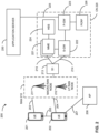
- Fig. 2 illustrates an architecture of a system 200 of a network in accordance with some embodiments.
- the system 200 is shown to include a user equipment (UE) 201 and a UE 202.
- the UEs 201 and 202 are illustrated as smartphones (e.g., handheld touchscreen mobile computing devices connectable to one or more cellular networks), but may also comprise any mobile or non-mobile computing device, or any computing device including a wireless communications interface. These UEs could include NR UEs.
- the UEs 201 and 202 may be configured to connect, e.g., communicatively couple, with a radio access network (RAN) 210.
- RAN radio access network
- the UEs 201 and 202 utilize connections 203 and 204, respectively, each of which comprises a physical communications interface or layer (discussed in further detail below); in this example, the connections 203 and 204 are illustrated as an air interface to enable communicative coupling, and can be consistent with cellular communications protocols.
- the UEs 201 and 202 may further directly exchange communication data via a ProSe interface 205.
- the ProSe interface 205 may alternatively be referred to as a sidelink interface comprising one or more logical channels, including but not limited to a Physical Sidelink Control Channel (PSCCH), a Physical Sidelink Shared Channel (PSSCH), a Physical Sidelink Discovery Channel (PSDCH), and a Physical Sidelink Broadcast Channel (PSBCH).
- PSCCH Physical Sidelink Control Channel
- PSSCH Physical Sidelink Shared Channel
- PSDCH Physical Sidelink Discovery Channel
- PSBCH Physical Sidelink Broadcast Channel
- the UE 202 is shown to be configured to access an access point (AP) 206 via connection 207.
- the connection 207 can comprise a local wireless connection, such as a connection consistent with any IEEE 802.11 protocol, wherein the AP 206 would comprise a wireless fidelity (WiFi ® ) router.
- WiFi ® wireless fidelity
- the AP 206 is shown to be connected to the Internet without connecting to the core network of the wireless system (described in further detail below).
- the RAN 210 can include one or more access nodes that enable the connections 203 and 204.
- These access nodes can be referred to as base stations (BSs), NodeBs, evolved NodeBs (eNBs), next Generation NodeBs (gNodeB), RAN nodes, and so forth, and can comprise ground stations (e.g., terrestrial access points) or satellite stations providing coverage within a geographic area (e.g., a cell).
- BSs base stations
- NodeBs evolved NodeBs
- gNodeB next Generation NodeBs
- RAN nodes and so forth, and can comprise ground stations (e.g., terrestrial access points) or satellite stations providing coverage within a geographic area (e.g., a cell).
- the RAN 210 may include one or more RAN nodes for providing macrocells, e.g., macro RAN node 211, and one or more RAN nodes for providing femtocells or picocells (e.g., cells having smaller coverage areas, smaller user capacity, or higher bandwidth compared to macrocells), e.g., low power (LP) RAN node 212.
- macro RAN node 211 e.g., macro RAN node 211
- femtocells or picocells e.g., cells having smaller coverage areas, smaller user capacity, or higher bandwidth compared to macrocells
- LP low power
- the UEs 201 and 202 can be configured to communicate using Orthogonal Frequency-Division Multiplexing (OFDM) communication signals with each other or with any of the RAN nodes 211 and 212 over a multicarrier communication channel in accordance various communication techniques, such as, but not limited to, an Orthogonal Frequency-Division Multiple Access (OFDMA) communication technique (e.g., for downlink communications) or a Single Carrier Frequency Division Multiple Access (SC-FDMA) communication technique (e.g., for uplink and ProSe or sidelink communications), although the scope of the embodiments is not limited in this respect.
- OFDM signals can comprise a plurality of orthogonal subcarriers.
- a downlink resource grid can be used for downlink transmissions from any of the RAN nodes 211 and 212 to the UEs 201 and 202, while uplink transmissions can utilize similar techniques.
- the grid can be a time-frequency grid, called a resource grid or time-frequency resource grid, which is the physical resource in the downlink in each slot.
- a time-frequency plane representation is a common practice for OFDM systems, which makes it intuitive for radio resource allocation.
- the RAN 210 is shown to be communicatively coupled to a core network (CN) 220 -via an S1 interface 213.
- the CN 220 may be an evolved packet core (EPC) network, a NextGen Packet Core (NPC) network, or some other type of CN.
- EPC evolved packet core
- NPC NextGen Packet Core
- the S1 interface 213 is split into two parts: the S1-U interface 214, which carries traffic data between the RAN nodes 211 and 212 and the serving gateway (S-GW) 222, and the S1-mobility management entity (MME) interface 215, which is a signaling interface between the RAN nodes 211 and 212 and MMEs 221.
- the CN 220 includes network elements.
- network element may describe a physical or virtualized equipment used to provide wired or wireless communication network services.
- network element may be considered synonymous to and/or referred to as a networked computer, networking hardware, network equipment, router, switch, hub, bridge, radio network controller, radio access network device, gateway, server, VNF, NFVI, and/or the like.
- the CN 220 comprises, as network elements, the MMEs 221, the S-GW 222, the Packet Data Network (PDN) Gateway (P-GW) 223, and a home subscriber server (HSS) 224.
- the MMEs 221 may be similar in function to the control plane of legacy Serving General Packet Radio Service (GPRS) Support Nodes (SGSN).
- the MMEs 221 may manage mobility aspects in access such as gateway selection and tracking area list management.
- the HSS 224 may comprise a database for network users, including subscription-related information to support the network entities' handling of communication sessions.
- the CN 220 may comprise one or several HSSs 224, depending on the number of mobile subscribers, on the capacity of the equipment, on the organization of the network, etc.
- the HSS 224 can provide support for routing/roaming, authentication, authorization, naming/addressing resolution, location dependencies, etc.
- the S-GW 222 may terminate the S1 interface 213 towards the RAN 210, and routes data packets between the RAN 210 and the CN 220.
- the S-GW 222 may be a local mobility anchor point for inter-RAN node handovers and also may provide an anchor for inter-3GPP mobility. Other responsibilities may include lawful intercept, charging, and some policy enforcement.
- the P-GW 223 may terminate an SGi interface toward a PDN.
- the P-GW 223 may route data packets between the EPC network 223 and external networks such as a network including the application server 230 (alternatively referred to as application function (AF)) via an Internet Protocol (IP) interface 225.
- the application server 230 may be an element offering applications that use IP bearer resources with the core network (e.g., UMTS Packet Services (PS) domain, LTE PS data services, etc.).
- PS UMTS Packet Services
- LTE PS data services etc.
- the P-GW 223 is shown to be communicatively coupled to an application server 230 via an IP communications interface 225.
- the application server 230 can also be configured to support one or more communication services (e.g., Voice-over-Internet Protocol (VoIP) sessions, PTT sessions, group communication sessions, social networking services, etc.) for the UEs 201 and 202 via the CN 220.
- VoIP Voice-over-Internet Protocol
- PTT sessions PTT sessions
- group communication sessions social networking services, etc.
- the P-GW 223 may further be a node for policy enforcement and charging data collection.
- Policy and Charging Enforcement Function (PCRF) 226 is the policy and charging control element of the CN 220.
- the PCRF 226 may be communicatively coupled to the application server 230 via the P-GW 223.
- the application server 230 may signal the PCRF 226 to indicate a new service flow and select the appropriate Quality of Service (QoS) and charging parameters.
- QoS Quality of Service
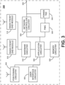
- Fig. 3 illustrates an example of infrastructure equipment 300 in accordance with various embodiments.
- the infrastructure equipment 300 (or "system 300") may be implemented as a base station, radio head, RAN node, etc., such as the RAN nodes 211 and/or AP 206 shown and described previously.
- the system 300 could be implemented in or by a UE, application server(s) 230, and/or any other element/device discussed herein.
- the system 300 may include one or more of application circuitry 305, baseband circuitry 310, one or more radio front end modules 315, memory circuitry 320, power management integrated circuitry (PMIC) 345, power tee circuitry 330, network controller circuitry 335, network interface connector 320, satellite positioning circuitry 345, and user interface 350.
- the device 300 may include additional elements such as, for example, memory/storage, display, camera, sensor, or input/output (I/O) interface.
- the components described below may be included in more than one device (e.g., said circuitries may be separately included in more than one device for CRAN, vBBU, or other like implementations).
- circuitry may refer to, is part of, or includes hardware components such as an electronic circuit, a logic circuit, a processor (shared, dedicated, or group) and/or memory (shared, dedicated, or group), an Application Specific Integrated Circuit (ASIC), a field-programmable device (FPD) (e.g., a field-programmable gate array (FPGA), a programmable logic device (PLD), a complex PLD (CPLD), a high-capacity PLD (HCPLD), a structured ASIC, or a programmable System on Chip (SoC)), digital signal processors (DSPs), etc., that are configured to provide the described functionality.
- FPD field-programmable device
- FPGA field-programmable gate array
- PLD programmable logic device
- CPLD complex PLD
- HPLD high-capacity PLD
- SoC programmable System on Chip
- DSPs digital signal processors
- the circuitry may execute one or more software or firmware programs to provide at least some of the described functionality.
- the term "circuitry” may also refer to a combination of one or more hardware elements (or a combination of circuits used in an electrical or electronic system) with the program code used to carry out the functionality of that program code. In these embodiments, the combination of hardware elements and program code may be referred to as a particular type of circuitry.
- processor circuitry may refer to, is part of, or includes circuitry capable of sequentially and automatically carrying out a sequence of arithmetic or logical operations, or recording, storing, and/or transferring digital data.
- processor circuitry may refer to one or more application processors, one or more baseband processors, a physical central processing unit (CPU), a single-core processor, a dual-core processor, a triple-core processor, a quad-core processor, and/or any other device capable of executing or otherwise operating computer-executable instructions, such as program code, software modules, and/or functional processes.
- CPU central processing unit
- network elements may describe a physical or virtualized equipment used to provide wired or wireless communication network services.
- network element may be considered synonymous to and/or referred to as a networked computer, networking hardware, network equipment, network node, router, switch, hub, bridge, radio network controller, RAN device, gateway, server, virtualized VNF, NFVI, and/or the like.
- Application circuitry 305 may include one or more central processing unit (CPU) cores and one or more of cache memory, low drop-out voltage regulators (LDOs), interrupt controllers, serial interfaces such as SPI, I2C or universal programmable serial interface module, real time clock (RTC), timer-counters including interval and watchdog timers, general purpose input/output (I/O or IO), memory card controllers such as Secure Digital (SD) MultiMediaCard (MMC) or similar, Universal Serial Bus (USB) interfaces, Mobile Industry Processor Interface (MIPI) interfaces and Joint Test Access Group (JTAG) test access ports.
- CPU central processing unit
- LDOs low drop-out voltage regulators
- interrupt controllers serial interfaces such as SPI, I2C or universal programmable serial interface module
- RTC real time clock
- timer-counters including interval and watchdog timers
- I/O or IO general purpose input/output
- memory card controllers such as Secure Digital (SD) MultiMediaCard (MMC
- application circuitry 305 may include circuitry such as, but not limited to, one or more a field-programmable devices (FPDs) such as field-programmable gate arrays (FPGAs) and the like; programmable logic devices (PLDs) such as complex PLDs (CPLDs), high-capacity PLDs (HCPLDs), and the like; ASICs such as structured ASICs and the like; programmable SoCs (PSoCs); and the like.
- FPDs field-programmable devices
- FPGAs field-programmable gate arrays
- PLDs programmable logic devices
- CPLDs complex PLDs
- HPLDs high-capacity PLDs
- ASICs such as structured ASICs and the like
- PSoCs programmable SoCs
- User interface circuitry 350 may include one or more user interfaces designed to enable user interaction with the system 300 or peripheral component interfaces designed to enable peripheral component interaction with the system 300.
- Peripheral component interfaces may include, but are not limited to, a nonvolatile memory port, a universal serial bus (USB) port, an audio jack, a power supply interface, etc.
- the radio front end modules (RFEMs) 315 may comprise a millimeter wave RFEM and one or more sub-millimeter wave radio frequency integrated circuits (RFICs).
- the one or more sub-millimeter wave RFICs may be physically separated from the millimeter wave RFEM.
- the RFICs may include connections to one or more antennas or antenna arrays, and the RFEM may be connected to multiple antennas.
- both millimeter wave and sub-millimeter wave radio functions may be implemented in the same physical radio front end module 315.
- the RFEMs 315 may incorporate both millimeter wave antennas and sub-millimeter wave antennas.
- the memory circuitry 320 may include one or more of volatile memory including dynamic random access memory (DRAM) and/or synchronous dynamic random access memory (SDRAM), and nonvolatile memory (NVM) including high-speed electrically erasable memory (commonly referred to as Flash memory), phase change random access memory (PRAM), magnetoresistive random access memory (MRAM), etc., and may incorporate the three-dimensional (3D) cross-point (XPOINT) memories from Intel ® and Micron ® .
- volatile memory including dynamic random access memory (DRAM) and/or synchronous dynamic random access memory (SDRAM), and nonvolatile memory (NVM) including high-speed electrically erasable memory (commonly referred to as Flash memory), phase change random access memory (PRAM), magnetoresistive random access memory (MRAM), etc.
- Flash memory commonly referred to as Flash memory
- PRAM phase change random access memory
- MRAM magnetoresistive random access memory
- XPOINT three-dimensional
- the PMIC 325 may include voltage regulators, surge protectors, power alarm detection circuitry, and one or more backup power sources such as a battery or capacitor.
- the network controller circuitry 335 may provide connectivity to a network using a standard network interface protocol such as Ethernet, Ethernet over GRE Tunnels, Ethernet over Multiprotocol Label Switching (MPLS), or some other suitable protocol.
- Network connectivity may be provided to/from the infrastructure equipment 300 via network interface connector 340 using a physical connection, which may be electrical (commonly referred to as a "copper interconnect"), optical, or wireless.
- the positioning circuitry 345 may include circuitry to receive and decode signals transmitted by one or more navigation satellite constellations of a global navigation satellite system (GNSS).
- GNSS global navigation satellite system
- interface circuitry may refer to, is part of, or includes circuitry providing for the exchange of information between two or more components or devices.
- interface circuitry may refer to one or more hardware interfaces, for example, buses, input/output (I/O) interfaces, peripheral component interfaces, network interface cards, and/or the like.
- the electronic device(s), network(s), system(s), chip(s) or component(s), or portions or implementations thereof, of one or more of the preceding figures, or some other figure herein may be configured to perform one or more processes, techniques, or methods as described herein, or portions thereof.
Landscapes
- Engineering & Computer Science (AREA)
- Signal Processing (AREA)
- Computer Networks & Wireless Communication (AREA)
- Quality & Reliability (AREA)
- Computer Security & Cryptography (AREA)
- Mobile Radio Communication Systems (AREA)
Claims (13)
- Vorrichtung eines Benutzergeräts, UE, (201 202), wobei die Vorrichtung einen Prozessor umfasst,
der konfiguriert ist zum:Decodieren (102) eines ersten Signals von einer Basisstation, die eine Vielzahl von Steuerressourcensätzen, CORESETs, konfiguriert;Empfangen einer Anzeige eines der konfigurierten der Vielzahl von CORESETs, der zu verwenden istzur Funkverbindungsüberwachung, RLM;Auswählen (104) eines CORESET basierend auf der Anzeige; undBestimmen (106) einer Downlink-Funkverbindungsqualität basierend auf dem CORESET. - Vorrichtung nach Anspruch 1, wobei ein zweites Signal Ressourcen für ein Referenzsignal, RS, in einer oder mehreren RLM-Referenzsignal-, RLM-RS-, Ressourcen umfasst, wobei die eine oder die mehreren RLM-RS-Ressourcen mindestens eines von allen Synchronisationssignalblock-, SSB-, Ressourcen, allen Kanalzustandsinformations-, CSI-, Referenzsignal-, CSI-RS-, Ressourcen oder einer Mischung aus SSB- und CSI-RS-Ressourcen umfassen, und wobei der Prozessor konfiguriert ist, um eine Downlink-Funkverbindungsqualität basierend auf dem RS zu bestimmen.
- Vorrichtung nach Anspruch 2, wobei der Prozessor konfiguriert ist, um die Downlink-Funkverbindungsqualität für jede RLM-RS-Ressource der einen oder der mehreren RLM-RS-Ressourcen durch Schätzen der Downlink-Funkverbindungsqualität und Vergleichen derselben mit Schwellenwerten Qout und Qin zu bestimmen, wobei Qout einer Out-of-Sync-Blockfehlerrate, BLERout, entspricht und Qin einer In-Sync-Blockfehlerrate, BLERin, entspricht.
- Vorrichtung nach Anspruch 3, wobei die eine oder die mehreren RLM-RS-Ressourcen SSB-Ressourcen umfassen, und der Prozessor konfiguriert ist zum:Bestimmen, ob die Downlink-Funkverbindungsqualität, die über eine letzte TEvaluate_out_SSB [MS]-Periode geschätzt wurde, schlechter als ein Schwellenwert Qout_SSB innerhalb einer TEvaluate_out_SSB [MS]-Bewertungsperiode wird; undBestimmen, ob die Downlink-Funkverbindungsqualität, die über eine letzte TEvaluate_out_SSB [MS]-Periode geschätzt wurde, besser als ein Schwellenwert Qin_SSB innerhalb einer TEvaluate_in_SSB [ms]-Bewertungsperiode wird, wobei TEvaluate_out_SSB und TEvaluate_in_SSB darauf basieren, ob ein Trägerfrequenzbereich für die eine oder die mehreren RLM-RS-Ressourcen einem NR FR1-Trägerfrequenzbereich oder einem NR FR2-Trägerfrequenzbereich entspricht.
- Vorrichtung nach Anspruch 3, wobei die eine oder die mehreren RLM-RS-Ressourcen CSI-RS-Ressourcen umfassen, und der Prozessor konfiguriert ist zum:Bestimmen, ob die Downlink-Funkverbindungsqualität, die über eine letzte TEvaluate_out_CSI-RS [MS]-Periode geschätzt wurde, schlechter als ein Schwellenwert Qout_CSI-RS innerhalb einer TEvaluate_out_CSI-RS [MS]-Bewertungsperiode wird; undBestimmen, ob die Downlink-Funkverbindungsqualität, die über eine letzte TEvaluate_in_CSI-RS [MS]-Periode geschätzt wurde, besser als ein Schwellenwert Qin_CSI-RS innerhalb einer TEvaluate_in_CSI-RS [ms]-Bewertungsperiode wird, wobei TEvaluate_out_CSI-Rs und TEvaluate_in_CSI-RS darauf basieren, ob ein Trägerfrequenzbereich für die eine oder die mehreren RLM-RS-Ressourcen einem NR FR1-Trägerfrequenzbereich oder einem NR FR2-Trägerfrequenzbereich entspricht.
- Vorrichtung nach Anspruch 3, wobei eine Bewertungsperiode zur Schätzung der Downlink-Funkverbindungsqualität darauf basiert, ob ein Trägerfrequenzbereich für die eine oder die mehreren RLM-RS-Ressourcen einem NR FR1-Trägerfrequenzbereich oder einem NR FR2-Trägerfrequenzbereich entspricht.
- Vorrichtung nach Anspruch 6, wobei die Bewertungsperiode ferner darauf basiert, ob eine Empfangskonfiguration einen diskontinuierlichen Empfangs-, DRX-, Modus umfasst.
- Vorrichtung nach Anspruch 2, wobei der Prozessor konfiguriert ist, um das UE zu veranlassen, bis zu XRLM-RS-RLM-RS-Ressourcen in jedem entsprechenden Trägerfrequenzbereich zu überwachen, wobei XRLM-RS 2 für NR FR1-Trägerfrequenzbereiche kleiner oder gleich 3 GHz, 4 für NR FR1-Trägerfrequenzbereiche über 3 GHz und 8 für NR FR2-Trägerfrequenzbereiche ist.
- Vorrichtung nach Anspruch 3, wobei der Prozessor konfiguriert ist, um eine hypothetische physikalische Downlink-Steuerkanal-, PDCCH-, Blockfehlerrate, BLER, basierend auf dem CORESET zu bestimmen und eine Out-of-Sync-, OOS-, Anzeige als Reaktion auf eine Bestimmung auszulösen, dass die BLER höher als ein OOS-Schwellenwert ist.
- Vorrichtung nach Anspruch 3, wobei der Prozessor konfiguriert ist, um BLERout und BLERin basierend auf einer Netzwerkkonfiguration über einen Parameter einer höheren Schicht oder basierend auf einer Konfigurationsnummer zu bestimmen.
- Vorrichtung nach Anspruch 7, wobei die Bewertungsperiode ferner auf mindestens einem von einem Subframe-Konfigurationszyklus, TCSI-RS, oder einem diskontinuierlichen Empfangszyklus, TDRX, basiert.
- Vorrichtung einer Basisstation, umfassend einen Prozessor, der konfiguriert ist zum:Codieren eines ersten Signals an ein Benutzergerät, UE, (201, 202), das eine Vielzahl von Steuerressourcensätzen, CORESETs, konfiguriert, um dem UE zu ermöglichen, ein CORESET basierend auf der Vielzahl von CORESETs auszuwählen;Codieren, in einem zweiten Signal, einer Anzeige von einem der konfigurierten Vielzahl von CORESETs, die zur Funkverbindungsüberwachung, RLM, verwendet werden soll;
undVeranlassen der Übertragung des ersten und zweiten Signals an das UE. - Vorrichtung nach Anspruch 12, wobei der Prozessor konfiguriert ist, um mindestens eine von einer Out-of-Sync-, OOS-, Anzeige von dem UE (201, 202) oder einer In-Sync-Anzeige von dem UE zu decodieren.
Applications Claiming Priority (2)
| Application Number | Priority Date | Filing Date | Title |
|---|---|---|---|
| US201862720025P | 2018-08-20 | 2018-08-20 | |
| PCT/US2019/047339 WO2020041366A1 (en) | 2018-08-20 | 2019-08-20 | Control resource set selection for channel state information reference signal-based radio link monitoring |
Publications (3)
| Publication Number | Publication Date |
|---|---|
| EP3811554A1 EP3811554A1 (de) | 2021-04-28 |
| EP3811554A4 EP3811554A4 (de) | 2022-03-23 |
| EP3811554B1 true EP3811554B1 (de) | 2024-12-18 |
Family
ID=69591462
Family Applications (1)
| Application Number | Title | Priority Date | Filing Date |
|---|---|---|---|
| EP19852775.6A Active EP3811554B1 (de) | 2018-08-20 | 2019-08-20 | Auswahl eines steuerresourcensatzes für auf kanalzustandsinformationsreferenzsignal basierte funkverbindungsüberwachung |
Country Status (3)
| Country | Link |
|---|---|
| US (1) | US12167435B2 (de) |
| EP (1) | EP3811554B1 (de) |
| WO (1) | WO2020041366A1 (de) |
Families Citing this family (12)
| Publication number | Priority date | Publication date | Assignee | Title |
|---|---|---|---|---|
| CA3065838A1 (en) * | 2018-02-05 | 2019-08-08 | Guangdong Oppo Mobile Telecommunications Corp., Ltd. | Link quality detection method and terminal device |
| CN110475276B (zh) | 2018-05-10 | 2023-11-07 | 夏普株式会社 | 用户设备中的链路评估方法及用户设备 |
| EP3811554B1 (de) * | 2018-08-20 | 2024-12-18 | Apple Inc. | Auswahl eines steuerresourcensatzes für auf kanalzustandsinformationsreferenzsignal basierte funkverbindungsüberwachung |
| US11477676B2 (en) * | 2018-11-02 | 2022-10-18 | Apple Inc. | RLM enhancements for 5G networks |
| US11109448B2 (en) * | 2018-12-11 | 2021-08-31 | Samsung Electronics Co., Ltd. | Method and apparatus for timing configuration of discovery signal and channel |
| WO2021161434A1 (ja) * | 2020-02-12 | 2021-08-19 | 株式会社Nttドコモ | 端末及び基地局 |
| EP4106383A4 (de) * | 2020-02-13 | 2023-11-08 | Ntt Docomo, Inc. | Endgerät, funkkommunikationsverfahren und basisstation |
| WO2021182863A1 (ko) * | 2020-03-10 | 2021-09-16 | 엘지전자 주식회사 | 무선 통신 시스템에서 무선 링크 품질 평가 방법 및 장치 |
| US12143255B2 (en) | 2020-07-29 | 2024-11-12 | Apple Inc. | Subcarrier spacing restriction for SSB, CSI-RS for L3 mobility, and PDCCH/PDSCH |
| CN117121393A (zh) * | 2021-04-02 | 2023-11-24 | 联想(新加坡)私人有限公司 | 基于准共址性质的通信 |
| CN117354932A (zh) * | 2022-06-29 | 2024-01-05 | 上海朗帛通信技术有限公司 | 一种被用于无线通信的方法和设备 |
| CN117580064B (zh) * | 2023-08-11 | 2024-10-11 | 中国电信股份有限公司技术创新中心 | 上报子配置的选择方法、装置、网络设备、终端和介质 |
Family Cites Families (27)
| Publication number | Priority date | Publication date | Assignee | Title |
|---|---|---|---|---|
| CN110447175B (zh) | 2016-12-27 | 2023-01-24 | 5G Ip控股有限责任公司 | 用于发送bwp指示符和使用相同的无线电通信设备的方法 |
| CN108365928B (zh) * | 2017-01-26 | 2023-04-07 | 北京三星通信技术研究有限公司 | 配置信息的发送方法、控制信道资源的检测方法和装置 |
| US10148337B2 (en) * | 2017-02-01 | 2018-12-04 | Samsung Electronics Co., Ltd. | Beam management of downlink data channel and downlink control channel for 5G next radio systems |
| ES2924708T3 (es) * | 2017-02-06 | 2022-10-10 | Ericsson Telefon Ab L M | Transmisiones de datos en regiones de control |
| EP3579607B1 (de) * | 2017-02-06 | 2024-07-31 | LG Electronics Inc. | Verfahren zur überwachung einer drahtlosen verbindung durch ein endgerät in einem drahtloskommunikationssystem und vorrichtung zur unterstützung davon |
| US10355813B2 (en) * | 2017-02-14 | 2019-07-16 | At&T Intellectual Property I, L.P. | Link adaptation on downlink control channel in a wireless communications system |
| KR102271539B1 (ko) * | 2017-06-23 | 2021-06-30 | 후아웨이 테크놀러지 컴퍼니 리미티드 | Nr에서의 통합 rlf 검출, 다중 빔 rlm 및 풀-다이버시티 bfr 메커니즘 |
| CN109392140B (zh) * | 2017-08-11 | 2020-07-28 | 维沃移动通信有限公司 | 一种用于监听pdcch的方法、终端及网络设备 |
| US11206655B2 (en) * | 2017-08-11 | 2021-12-21 | Electronics And Telecommunications Research Institute | Method for transmitting or receiving downlink control channel and device using same |
| CN109495966B (zh) * | 2017-09-11 | 2022-04-29 | 大唐移动通信设备有限公司 | 用于传输下行数据的资源的确定和配置方法、终端和基站 |
| US10784943B2 (en) * | 2017-10-23 | 2020-09-22 | Apple, Inc. | Beam failure recovery operation |
| WO2019097633A1 (ja) * | 2017-11-16 | 2019-05-23 | 株式会社Nttドコモ | ユーザ端末及び無線通信方法 |
| JP7079326B2 (ja) * | 2017-11-16 | 2022-06-01 | テレフオンアクチーボラゲット エルエム エリクソン(パブル) | 帯域幅部分切替え時の無線リンク監視/無線リンク失敗再設定 |
| US11206596B2 (en) * | 2017-11-27 | 2021-12-21 | Asustek Computer Inc. | Method and apparatus for reducing interruption of beaming recovery procedure in a wireless communication system |
| CN110035558B (zh) * | 2018-01-11 | 2021-03-26 | 华硕电脑股份有限公司 | 通过随机接入程序恢复波束失效的方法和设备 |
| EP3739768A4 (de) * | 2018-01-12 | 2021-08-11 | Ntt Docomo, Inc. | Benutzerendgerät und drahtloskommunikationsverfahren |
| WO2019138070A1 (en) * | 2018-01-12 | 2019-07-18 | Nokia Technologies Oy | Coreset and qcl association in beam recovery procedure |
| US10893431B2 (en) * | 2018-01-19 | 2021-01-12 | Asustek Computer Inc. | Method and apparatus for beam failure reporting under multicell configuration in a wireless communication system |
| US11025348B2 (en) * | 2018-02-16 | 2021-06-01 | Qualcomm Incorporated | Default radio link monitoring reference signal (RLM-RS) determination procedure in new radio (NR) |
| EP3753193B1 (de) * | 2018-02-16 | 2024-01-03 | Lenovo (Singapore) Pte. Ltd. | Zur bandbreitenteilen gehörende ressourcen |
| US11368956B2 (en) * | 2018-04-05 | 2022-06-21 | Qualcomm Incorporated | Radio link management under bandwidth part switching |
| US10841816B2 (en) * | 2018-04-13 | 2020-11-17 | Nokia Technologies Oy | Configuration of failure detection reference signals |
| KR102083568B1 (ko) * | 2018-05-09 | 2020-03-02 | 엘지전자 주식회사 | 무선 통신 시스템에서 단말의 제어 채널 모니터링 방법 및 상기 방법을 이용하는 단말 |
| US11316577B2 (en) * | 2018-05-11 | 2022-04-26 | Qualcomm Incorporated | Signaling of control resource set (CORESET) |
| US20190393980A1 (en) * | 2018-06-22 | 2019-12-26 | Mediatek Inc. | Method for NR Radio Link Monitoring (RLM) and Evaluation Period Determination |
| EP3811554B1 (de) * | 2018-08-20 | 2024-12-18 | Apple Inc. | Auswahl eines steuerresourcensatzes für auf kanalzustandsinformationsreferenzsignal basierte funkverbindungsüberwachung |
| US11824608B2 (en) * | 2020-02-10 | 2023-11-21 | Qualcomm Incorporated | Channel state information (CSI) processing unit procedures for CSI report pre-emption |
-
2019
- 2019-08-20 EP EP19852775.6A patent/EP3811554B1/de active Active
- 2019-08-20 WO PCT/US2019/047339 patent/WO2020041366A1/en not_active Ceased
- 2019-08-20 US US17/268,198 patent/US12167435B2/en active Active
Also Published As
| Publication number | Publication date |
|---|---|
| EP3811554A1 (de) | 2021-04-28 |
| EP3811554A4 (de) | 2022-03-23 |
| US12167435B2 (en) | 2024-12-10 |
| WO2020041366A1 (en) | 2020-02-27 |
| US20210185694A1 (en) | 2021-06-17 |
Similar Documents
| Publication | Publication Date | Title |
|---|---|---|
| EP3811554B1 (de) | Auswahl eines steuerresourcensatzes für auf kanalzustandsinformationsreferenzsignal basierte funkverbindungsüberwachung | |
| US20220376863A1 (en) | Radio Link Monitoring/Radio Link Failure Reconfiguration Upon Bandwidth Parts Switching | |
| US11166183B2 (en) | Measurement gap and synchronization signal block—based measurement timing configuration scheduling | |
| US12395869B2 (en) | Radio link monitoring enhancements for power savings | |
| US20240073813A1 (en) | SCell Activation Enhancement with Assistance Reference Signal | |
| US10873962B2 (en) | Mechanisms for handling uplink grants indicating different physical uplink shared channel starting positions in a same subframe | |
| US11979904B2 (en) | Detection of listen before talk failure during radio link monitoring | |
| EP3863319B1 (de) | Verfahren, durchgeführt durch ein benutzerendgeraet, und benutzerendgeraet | |
| EP4074098A1 (de) | Verfahren, um einem drahtlosen gerät mit reduzierter bandbreite zu ermöglichen, auf eine zelle zuzugreifen | |
| AU2024227282B2 (en) | On-demand procedure for requesting 5G time reference | |
| CN113875183B (zh) | 发送和接收指示 | |
| US11363608B2 (en) | Unlicensed narrowband internet of things control channel communication | |
| WO2015106715A1 (zh) | 信号传输方法和装置 | |
| US20220346157A1 (en) | Configuration for Random Access Procedure | |
| CN116711396A (zh) | 用于增强的ue功率节省的5g nr trs/csi-rs信令方面 | |
| WO2019029583A1 (zh) | 获取定时偏差的方法及相关设备 | |
| WO2022152427A1 (en) | User equipment and base station involved in paging | |
| ES2983857T3 (es) | Métodos de señalización de recursos reservados para el tráfico de comunicación ultraconfiable de baja latencia (URLLC) | |
| US20240163829A1 (en) | Aperiodic and Semi-Persistent Positioning Reference Signal and Measurement Gaps | |
| WO2020033897A1 (en) | Techniques of determining an orthogonal cover code index for physical uplink control channel (pucch) transmission prior to radio resource control (rrc) setup for new radio (nr) | |
| US20240032141A1 (en) | SSB Enhancement for NR CDRX and DRX Operation | |
| CN120937442A (zh) | 用于网络功率节省模式的增强型移动性操作 | |
| CN121100562A (zh) | 用于能力降低的用户装备的eDRX增强 |
Legal Events
| Date | Code | Title | Description |
|---|---|---|---|
| STAA | Information on the status of an ep patent application or granted ep patent |
Free format text: STATUS: THE INTERNATIONAL PUBLICATION HAS BEEN MADE |
|
| PUAI | Public reference made under article 153(3) epc to a published international application that has entered the european phase |
Free format text: ORIGINAL CODE: 0009012 |
|
| STAA | Information on the status of an ep patent application or granted ep patent |
Free format text: STATUS: REQUEST FOR EXAMINATION WAS MADE |
|
| 17P | Request for examination filed |
Effective date: 20210113 |
|
| AK | Designated contracting states |
Kind code of ref document: A1 Designated state(s): AL AT BE BG CH CY CZ DE DK EE ES FI FR GB GR HR HU IE IS IT LI LT LU LV MC MK MT NL NO PL PT RO RS SE SI SK SM TR |
|
| AX | Request for extension of the european patent |
Extension state: BA ME |
|
| DAV | Request for validation of the european patent (deleted) | ||
| DAX | Request for extension of the european patent (deleted) | ||
| REG | Reference to a national code |
Ref country code: HK Ref legal event code: DE Ref document number: 40050330 Country of ref document: HK |
|
| A4 | Supplementary search report drawn up and despatched |
Effective date: 20220218 |
|
| RIC1 | Information provided on ipc code assigned before grant |
Ipc: H04W 72/08 20090101ALI20220215BHEP Ipc: H04W 72/04 20090101ALI20220215BHEP Ipc: H04W 24/10 20090101ALI20220215BHEP Ipc: H04L 5/00 20060101AFI20220215BHEP |
|
| STAA | Information on the status of an ep patent application or granted ep patent |
Free format text: STATUS: EXAMINATION IS IN PROGRESS |
|
| 17Q | First examination report despatched |
Effective date: 20230310 |
|
| RIC1 | Information provided on ipc code assigned before grant |
Ipc: H04L 5/00 20060101AFI20240531BHEP |
|
| GRAP | Despatch of communication of intention to grant a patent |
Free format text: ORIGINAL CODE: EPIDOSNIGR1 |
|
| STAA | Information on the status of an ep patent application or granted ep patent |
Free format text: STATUS: GRANT OF PATENT IS INTENDED |
|
| INTG | Intention to grant announced |
Effective date: 20240712 |
|
| GRAS | Grant fee paid |
Free format text: ORIGINAL CODE: EPIDOSNIGR3 |
|
| GRAA | (expected) grant |
Free format text: ORIGINAL CODE: 0009210 |
|
| STAA | Information on the status of an ep patent application or granted ep patent |
Free format text: STATUS: THE PATENT HAS BEEN GRANTED |
|
| RAP3 | Party data changed (applicant data changed or rights of an application transferred) |
Owner name: APPLE INC. |
|
| AK | Designated contracting states |
Kind code of ref document: B1 Designated state(s): AL AT BE BG CH CY CZ DE DK EE ES FI FR GB GR HR HU IE IS IT LI LT LU LV MC MK MT NL NO PL PT RO RS SE SI SK SM TR |
|
| REG | Reference to a national code |
Ref country code: CH Ref legal event code: EP |
|
| REG | Reference to a national code |
Ref country code: DE Ref legal event code: R096 Ref document number: 602019063771 Country of ref document: DE |
|
| REG | Reference to a national code |
Ref country code: IE Ref legal event code: FG4D |
|
| REG | Reference to a national code |
Ref country code: LT Ref legal event code: MG9D |
|
| PG25 | Lapsed in a contracting state [announced via postgrant information from national office to epo] |
Ref country code: HR Free format text: LAPSE BECAUSE OF FAILURE TO SUBMIT A TRANSLATION OF THE DESCRIPTION OR TO PAY THE FEE WITHIN THE PRESCRIBED TIME-LIMIT Effective date: 20241218 |
|
| PG25 | Lapsed in a contracting state [announced via postgrant information from national office to epo] |
Ref country code: FI Free format text: LAPSE BECAUSE OF FAILURE TO SUBMIT A TRANSLATION OF THE DESCRIPTION OR TO PAY THE FEE WITHIN THE PRESCRIBED TIME-LIMIT Effective date: 20241218 |
|
| PG25 | Lapsed in a contracting state [announced via postgrant information from national office to epo] |
Ref country code: BG Free format text: LAPSE BECAUSE OF FAILURE TO SUBMIT A TRANSLATION OF THE DESCRIPTION OR TO PAY THE FEE WITHIN THE PRESCRIBED TIME-LIMIT Effective date: 20241218 |
|
| PG25 | Lapsed in a contracting state [announced via postgrant information from national office to epo] |
Ref country code: NO Free format text: LAPSE BECAUSE OF FAILURE TO SUBMIT A TRANSLATION OF THE DESCRIPTION OR TO PAY THE FEE WITHIN THE PRESCRIBED TIME-LIMIT Effective date: 20250318 |
|
| REG | Reference to a national code |
Ref country code: NL Ref legal event code: MP Effective date: 20241218 |
|
| PG25 | Lapsed in a contracting state [announced via postgrant information from national office to epo] |
Ref country code: LV Free format text: LAPSE BECAUSE OF FAILURE TO SUBMIT A TRANSLATION OF THE DESCRIPTION OR TO PAY THE FEE WITHIN THE PRESCRIBED TIME-LIMIT Effective date: 20241218 Ref country code: GR Free format text: LAPSE BECAUSE OF FAILURE TO SUBMIT A TRANSLATION OF THE DESCRIPTION OR TO PAY THE FEE WITHIN THE PRESCRIBED TIME-LIMIT Effective date: 20250319 |
|
| PG25 | Lapsed in a contracting state [announced via postgrant information from national office to epo] |
Ref country code: RS Free format text: LAPSE BECAUSE OF FAILURE TO SUBMIT A TRANSLATION OF THE DESCRIPTION OR TO PAY THE FEE WITHIN THE PRESCRIBED TIME-LIMIT Effective date: 20250318 |
|
| PG25 | Lapsed in a contracting state [announced via postgrant information from national office to epo] |
Ref country code: NL Free format text: LAPSE BECAUSE OF FAILURE TO SUBMIT A TRANSLATION OF THE DESCRIPTION OR TO PAY THE FEE WITHIN THE PRESCRIBED TIME-LIMIT Effective date: 20241218 |
|
| REG | Reference to a national code |
Ref country code: AT Ref legal event code: MK05 Ref document number: 1753121 Country of ref document: AT Kind code of ref document: T Effective date: 20241218 |
|
| PG25 | Lapsed in a contracting state [announced via postgrant information from national office to epo] |
Ref country code: SM Free format text: LAPSE BECAUSE OF FAILURE TO SUBMIT A TRANSLATION OF THE DESCRIPTION OR TO PAY THE FEE WITHIN THE PRESCRIBED TIME-LIMIT Effective date: 20241218 |
|
| PG25 | Lapsed in a contracting state [announced via postgrant information from national office to epo] |
Ref country code: PL Free format text: LAPSE BECAUSE OF FAILURE TO SUBMIT A TRANSLATION OF THE DESCRIPTION OR TO PAY THE FEE WITHIN THE PRESCRIBED TIME-LIMIT Effective date: 20241218 |
|
| PG25 | Lapsed in a contracting state [announced via postgrant information from national office to epo] |
Ref country code: ES Free format text: LAPSE BECAUSE OF FAILURE TO SUBMIT A TRANSLATION OF THE DESCRIPTION OR TO PAY THE FEE WITHIN THE PRESCRIBED TIME-LIMIT Effective date: 20241218 |
|
| PG25 | Lapsed in a contracting state [announced via postgrant information from national office to epo] |
Ref country code: IS Free format text: LAPSE BECAUSE OF FAILURE TO SUBMIT A TRANSLATION OF THE DESCRIPTION OR TO PAY THE FEE WITHIN THE PRESCRIBED TIME-LIMIT Effective date: 20250418 |
|
| PG25 | Lapsed in a contracting state [announced via postgrant information from national office to epo] |
Ref country code: PT Free format text: LAPSE BECAUSE OF FAILURE TO SUBMIT A TRANSLATION OF THE DESCRIPTION OR TO PAY THE FEE WITHIN THE PRESCRIBED TIME-LIMIT Effective date: 20250421 |
|
| PG25 | Lapsed in a contracting state [announced via postgrant information from national office to epo] |
Ref country code: EE Free format text: LAPSE BECAUSE OF FAILURE TO SUBMIT A TRANSLATION OF THE DESCRIPTION OR TO PAY THE FEE WITHIN THE PRESCRIBED TIME-LIMIT Effective date: 20241218 |
|
| PG25 | Lapsed in a contracting state [announced via postgrant information from national office to epo] |
Ref country code: AT Free format text: LAPSE BECAUSE OF FAILURE TO SUBMIT A TRANSLATION OF THE DESCRIPTION OR TO PAY THE FEE WITHIN THE PRESCRIBED TIME-LIMIT Effective date: 20241218 Ref country code: RO Free format text: LAPSE BECAUSE OF FAILURE TO SUBMIT A TRANSLATION OF THE DESCRIPTION OR TO PAY THE FEE WITHIN THE PRESCRIBED TIME-LIMIT Effective date: 20241218 |
|
| PG25 | Lapsed in a contracting state [announced via postgrant information from national office to epo] |
Ref country code: SK Free format text: LAPSE BECAUSE OF FAILURE TO SUBMIT A TRANSLATION OF THE DESCRIPTION OR TO PAY THE FEE WITHIN THE PRESCRIBED TIME-LIMIT Effective date: 20241218 |
|
| PG25 | Lapsed in a contracting state [announced via postgrant information from national office to epo] |
Ref country code: CZ Free format text: LAPSE BECAUSE OF FAILURE TO SUBMIT A TRANSLATION OF THE DESCRIPTION OR TO PAY THE FEE WITHIN THE PRESCRIBED TIME-LIMIT Effective date: 20241218 |
|
| PG25 | Lapsed in a contracting state [announced via postgrant information from national office to epo] |
Ref country code: IT Free format text: LAPSE BECAUSE OF FAILURE TO SUBMIT A TRANSLATION OF THE DESCRIPTION OR TO PAY THE FEE WITHIN THE PRESCRIBED TIME-LIMIT Effective date: 20241218 |
|
| PG25 | Lapsed in a contracting state [announced via postgrant information from national office to epo] |
Ref country code: SE Free format text: LAPSE BECAUSE OF FAILURE TO SUBMIT A TRANSLATION OF THE DESCRIPTION OR TO PAY THE FEE WITHIN THE PRESCRIBED TIME-LIMIT Effective date: 20241218 |
|
| REG | Reference to a national code |
Ref country code: DE Ref legal event code: R097 Ref document number: 602019063771 Country of ref document: DE |
|
| PG25 | Lapsed in a contracting state [announced via postgrant information from national office to epo] |
Ref country code: DK Free format text: LAPSE BECAUSE OF FAILURE TO SUBMIT A TRANSLATION OF THE DESCRIPTION OR TO PAY THE FEE WITHIN THE PRESCRIBED TIME-LIMIT Effective date: 20241218 |
|
| PLBE | No opposition filed within time limit |
Free format text: ORIGINAL CODE: 0009261 |
|
| STAA | Information on the status of an ep patent application or granted ep patent |
Free format text: STATUS: NO OPPOSITION FILED WITHIN TIME LIMIT |
|
| REG | Reference to a national code |
Ref country code: CH Ref legal event code: L10 Free format text: ST27 STATUS EVENT CODE: U-0-0-L10-L00 (AS PROVIDED BY THE NATIONAL OFFICE) Effective date: 20251029 |
|
| 26N | No opposition filed |
Effective date: 20250919 |
|
| REG | Reference to a national code |
Ref country code: DE Ref legal event code: R119 Ref document number: 602019063771 Country of ref document: DE |
|
| REG | Reference to a national code |
Ref country code: CH Ref legal event code: H13 Free format text: ST27 STATUS EVENT CODE: U-0-0-H10-H13 (AS PROVIDED BY THE NATIONAL OFFICE) Effective date: 20260324 |
|
| PG25 | Lapsed in a contracting state [announced via postgrant information from national office to epo] |
Ref country code: MC Free format text: LAPSE BECAUSE OF FAILURE TO SUBMIT A TRANSLATION OF THE DESCRIPTION OR TO PAY THE FEE WITHIN THE PRESCRIBED TIME-LIMIT Effective date: 20241218 |
|
| PG25 | Lapsed in a contracting state [announced via postgrant information from national office to epo] |
Ref country code: LU Free format text: LAPSE BECAUSE OF NON-PAYMENT OF DUE FEES Effective date: 20250820 |