EP3811448B1 - Brennstoffzellenstapel - Google Patents
Brennstoffzellenstapel Download PDFInfo
- Publication number
- EP3811448B1 EP3811448B1 EP19725052.5A EP19725052A EP3811448B1 EP 3811448 B1 EP3811448 B1 EP 3811448B1 EP 19725052 A EP19725052 A EP 19725052A EP 3811448 B1 EP3811448 B1 EP 3811448B1
- Authority
- EP
- European Patent Office
- Prior art keywords
- fuel cell
- cell stack
- mounting shaft
- spring
- end plate
- Prior art date
- Legal status (The legal status is an assumption and is not a legal conclusion. Google has not performed a legal analysis and makes no representation as to the accuracy of the status listed.)
- Active
Links
Images

Classifications
-
- H—ELECTRICITY
- H01—ELECTRIC ELEMENTS
- H01M—PROCESSES OR MEANS, e.g. BATTERIES, FOR THE DIRECT CONVERSION OF CHEMICAL ENERGY INTO ELECTRICAL ENERGY
- H01M8/00—Fuel cells; Manufacture thereof
- H01M8/24—Grouping of fuel cells, e.g. stacking of fuel cells
- H01M8/2465—Details of groupings of fuel cells
- H01M8/247—Arrangements for tightening a stack, for accommodation of a stack in a tank or for assembling different tanks
- H01M8/248—Means for compression of the fuel cell stacks
-
- H—ELECTRICITY
- H01—ELECTRIC ELEMENTS
- H01M—PROCESSES OR MEANS, e.g. BATTERIES, FOR THE DIRECT CONVERSION OF CHEMICAL ENERGY INTO ELECTRICAL ENERGY
- H01M8/00—Fuel cells; Manufacture thereof
- H01M8/04—Auxiliary arrangements, e.g. for control of pressure or for circulation of fluids
- H01M8/04298—Processes for controlling fuel cells or fuel cell systems
- H01M8/04313—Processes for controlling fuel cells or fuel cell systems characterised by the detection or assessment of variables; characterised by the detection or assessment of failure or abnormal function
- H01M8/0438—Pressure; Ambient pressure; Flow
-
- H—ELECTRICITY
- H01—ELECTRIC ELEMENTS
- H01M—PROCESSES OR MEANS, e.g. BATTERIES, FOR THE DIRECT CONVERSION OF CHEMICAL ENERGY INTO ELECTRICAL ENERGY
- H01M8/00—Fuel cells; Manufacture thereof
- H01M8/04—Auxiliary arrangements, e.g. for control of pressure or for circulation of fluids
- H01M8/04298—Processes for controlling fuel cells or fuel cell systems
- H01M8/04694—Processes for controlling fuel cells or fuel cell systems characterised by variables to be controlled
- H01M8/04746—Pressure; Flow
-
- H—ELECTRICITY
- H01—ELECTRIC ELEMENTS
- H01M—PROCESSES OR MEANS, e.g. BATTERIES, FOR THE DIRECT CONVERSION OF CHEMICAL ENERGY INTO ELECTRICAL ENERGY
- H01M2250/00—Fuel cells for particular applications; Specific features of fuel cell system
- H01M2250/20—Fuel cells in motive systems, e.g. vehicle, ship, plane
-
- Y—GENERAL TAGGING OF NEW TECHNOLOGICAL DEVELOPMENTS; GENERAL TAGGING OF CROSS-SECTIONAL TECHNOLOGIES SPANNING OVER SEVERAL SECTIONS OF THE IPC; TECHNICAL SUBJECTS COVERED BY FORMER USPC CROSS-REFERENCE ART COLLECTIONS [XRACs] AND DIGESTS
- Y02—TECHNOLOGIES OR APPLICATIONS FOR MITIGATION OR ADAPTATION AGAINST CLIMATE CHANGE
- Y02E—REDUCTION OF GREENHOUSE GAS [GHG] EMISSIONS, RELATED TO ENERGY GENERATION, TRANSMISSION OR DISTRIBUTION
- Y02E60/00—Enabling technologies; Technologies with a potential or indirect contribution to GHG emissions mitigation
- Y02E60/30—Hydrogen technology
- Y02E60/50—Fuel cells
-
- Y—GENERAL TAGGING OF NEW TECHNOLOGICAL DEVELOPMENTS; GENERAL TAGGING OF CROSS-SECTIONAL TECHNOLOGIES SPANNING OVER SEVERAL SECTIONS OF THE IPC; TECHNICAL SUBJECTS COVERED BY FORMER USPC CROSS-REFERENCE ART COLLECTIONS [XRACs] AND DIGESTS
- Y02—TECHNOLOGIES OR APPLICATIONS FOR MITIGATION OR ADAPTATION AGAINST CLIMATE CHANGE
- Y02T—CLIMATE CHANGE MITIGATION TECHNOLOGIES RELATED TO TRANSPORTATION
- Y02T90/00—Enabling technologies or technologies with a potential or indirect contribution to GHG emissions mitigation
- Y02T90/40—Application of hydrogen technology to transportation, e.g. using fuel cells
Definitions
- Fuel cells use the chemical reaction of a fuel with oxygen to form water to generate electrical energy.
- fuel cells have a membrane electrode assembly (MEA) with a membrane electrode unit.
- MEA membrane electrode assembly
- the membrane-electrode unit is formed by a proton-conducting membrane, PEM, on which catalytic electrodes are arranged on both sides.
- PEM proton-conducting membrane
- the membrane separates the anode space assigned to the anode and the cathode space assigned to the cathode from one another and insulates them electrically.
- gas diffusion layers can be arranged on the sides of the electrodes that do not face the membrane.
- a hydrogen-containing fuel is supplied to the anode, at which an electrochemical oxidation of H 2 to H + takes place with the release of electrons.
- a water-bound or water-free transport of the protons H + from the anode compartment into the cathode compartment takes place via the electrolytic membrane.
- the electrons provided at the anode are fed to the cathode via an electrical line.
- An oxygen-containing operating medium is fed to the cathode, so that a reduction of O 2 to O 2 takes place there , with the electrons being absorbed.
- these oxygen anions react with the protons transported across the membrane to form water.
- a fuel cell stack is generally formed by a large number of MEAs arranged one above the other in a stack in the stacking direction, the electrical power of which is added up.
- Bipolar plates are usually arranged between the membrane-electrode assemblies, which ensure that the individual MEA is supplied with the reactants and a cooling liquid, and also function as an electrically conductive contact to the membrane-electrode assemblies.
- Seals are arranged between the membrane-electrode units and the bipolar plates in order to seal off the anode and cathode spaces from the outside and to prevent the operating media from escaping from the stack. These seals are provided on the membrane electrode assemblies, the bipolar plates, or both of these components.
- the fuel cell stack is pressed before it is put into operation. Furthermore, tension elements are used to compress the fuel cell stack during operation.
- tension elements are known from the prior art.
- two end plates arranged at the ends of the fuel cell stack can be connected by means of tension elements.
- the fuel cell stack is pressed together by introducing tensile forces into the end plates via the tensile elements.
- threaded rods, tie rods, chains or the like are used as tension elements.
- tensioned strip-like or band-like elastic tensioning elements which are either connected to the end plates or at least partially encircle the stack in at least one cross section (in the direction of the stack).
- tension elements is, for example, on the EP 1 870 952 A2 , the DE 10 2012 000 266 A1 and the WO 2012/065890 A1 referred to, the contents of which are hereby fully comprehensive is referred to.
- the elastic band elements there is no provision for the elastic band elements to be re-tightened.
- DE 10 2008 026858 A1 U.S. 2009/280359 A1 and WO 2011/098276 A1 Fuel cell stack with clamping elements.
- the DE 10 2010 007 979 A1 discloses a fuel cell stack with fuel cells arranged between two end plates and at least one bracing means connecting the end plates for exerting a tensile force.
- a friction-reducing deflection means is arranged between the bracing means and at least one of the end plates.
- a change in the height of the stack is intended to be compensated by compressed spring elements arranged between an end plate and a compression plate.
- stress peaks due to the expansion of the stack are to be avoided by elastic elements.
- An initial overstressing of the elastic elements should even be able to partially avoid a change in the height of the stack.
- the elastic elements themselves are subject to aging and at least in this respect this passive option for adjusting the compression force is disadvantageous.
- the DE 10 2010 007 981 A1 discloses a fuel cell stack with fuel cells arranged between two end plates and at least one bracing means connecting the end plates for exerting a tensile force.
- a fastening element which is designed as an eccentric element or contains an eccentric element, is arranged between the bracing means and at least one of the end plates. By rotating the fastening element, a distance between the end plates is intended to be changed and thus a tensile force between the end plates is to be adjusted.
- the compression system according to this prior art has a complicated structure which requires specially adapted end plates and/or bracing means and is not suitable for rotating tensioning elements.
- the invention is now based on the object of overcoming the disadvantages of the prior art and providing a solution for the permanent compression of fuel cell stacks, which can be integrated into existing fuel cell stacks to save space and reliably ensures that a compressive tensile force is maintained even over extended periods of time.
- a fuel cell stack having a first end plate and a second end plate and a multiplicity of fuel cells arranged between the two end plates in the stacking direction. Furthermore, the fuel cell stack has at least one elastic tensioning element tensioned between the end plates in the stacking direction.
- the fuel cell stack according to the invention also has at least one rotatable mounting shaft.
- the mounting shaft is preferably integrated into the fuel cell stack and particularly preferably rotatably mounted in or on the fuel cell stack.
- at least one end section, in particular a first end section, of at least one clamping element is fixed to the assembly shaft.
- the end section is preferably non-positively, materially and/or positively fixed to the mounting shaft in order to prevent relative movements between the end section and the mounting shaft.
- the rotatable assembly shaft is connected to the fuel cell stack via at least one tensioned torsion spring.
- the torsion spring is fixed to the mounting shaft and additionally to the fuel cell stack.
- a first end of the torsion spring such as a first end of a wire coiled into the spring
- a second end of the torsion spring such as a second end of the wire coiled into the spring
- the spring tension or the torque of the tensioned torsion spring is thus transmitted to the rotatably mounted assembly shaft.
- the torsion spring is preferably connected to the mounting shaft in such a way that a torque exerted by the spring opposes a tensile stress exerted by the tensioning element.
- the tensile stress of the at least one tensioning element can be adjusted by rotating the assembly shaft.
- the mounting shaft thus advantageously allows the at least one clamping element to be re-tensioned by turning the mounting shaft.
- a directed torque opposing the tensile stress of the clamping element is advantageously transmitted to the assembly shaft.
- the spring advantageously leads to retensioning of the tensioning element by means of the torque of the torsion spring.
- the fuel cell stack according to the invention is thus advantageously equipped to reliably ensure compression of the fuel cell stack via the end plates braced by means of tensioning elements, even over an extended period of time.
- Automatic retensioning of an elongated tensioning element is particularly advantageous by winding the tensioning element onto the assembly shaft by means of potential energy stored in at least one torsion spring. The winding only takes place when the tensile stress of the tensioning element falls below the torque of the torsion spring.
- the at least one tensioning element is effectively shortened between its end sections, thereby increasing the tensile force generated by it.
- the fuel cell stack according to the invention is advantageously designed to unwind a tensioning element from the mounting shaft again by rotating the mounting shaft in an opposite, second direction of rotation.
- the rotation in the second direction of rotation takes place in the direction of the tensile stress of the tensioning element and thus counter to a torque exerted by the torsion spring. Unwinding therefore only takes place when the tensile stress exceeds the torque.
- the tensioning element is effectively lengthened between its fixed points, thereby reducing the tensile force generated by it.
- a compressive tensile force generated by the tensioning elements exceeds a specific limit value determined by the torque of the at least one torsion spring.
- a second end section of the at least one clamping element is preferably also fixed to the fuel cell stack.
- the second end section is different from the first end section and each clamping element has a first and a second end section.
- the second end section is preferably fixed to the same mounting shaft as the first end section.
- a Turning the assembly shaft thus advantageously leads to twice as much shortening and thus to an increase in traction compared to only one attached end section.
- the second end section of the tensioning element is preferably fixed to a further assembly shaft.
- the additional mounting shaft is preferably also connected to the fuel cell stack via at least one tensioned torsion spring.
- the clamping element can thus advantageously be re-tensioned on both sides and thus particularly evenly and precisely.
- the second end section is also preferably firmly fixed to any other section of the fuel cell stack. This represents a particularly simple embodiment of the invention.
- the elastic tensioning element of the fuel cell stack is preferably tensioned in Hook's area. Re-tightening of the tensioning element preferably takes place in the stacking direction (S) of the fuel cell stack and preferably always along the tensioning direction of the tensioning elements. Particularly preferably, the spring force of the at least one torsion spring and thus the tensile stress of the at least one tensioning element can be adjusted by rotating the assembly shaft.
- the stack compression is preferably also set locally by arranging tensioned torsion springs with a specific spring force.
- the at least one tensioning element preferably each tensioning element of the fuel cell stack, is likewise preferably tensioned via a plurality of torsion springs connected to the at least one assembly shaft.
- the at least one tensioning element is fixed to a mounting shaft and the plurality of tensioned torsion springs are fixed to this mounting shaft and the fuel cell stack.
- the spring forces applied by the plurality of torsion springs thus add up to form a total spring force.
- the at least one mounting shaft runs along an edge region of the first or second end plate.
- the edge area of this end plate preferably designates a transition from a first, outwardly pointing surface of the end plate and a second surface of the endplate perpendicular to the first surface.
- the second surface preferably extends along the stacking direction of the fuel cell stack or has a normal vector perpendicular to the stacking direction.
- the tensioning elements advantageously do not run over edges of the fuel cell stack.
- the at least one assembly shaft is also preferably connected via the at least one tensioned torsion spring to the end plate, along the edge region of which it runs.
- a fuel cell stack can thus benefit from the advantages of the invention simply by adding appropriately equipped end plates.
- the mounting shaft is particularly preferably guided in sections through the end plate in the area of an edge area of the end plate.
- the end plate in this embodiment preferably has a cylindrical bore.
- a simple rotatable mounting of the mounting shaft can thus be advantageously realized.
- the end plate preferably has recesses or recesses in the edge area, in which the mounting shaft is exposed.
- the at least one tensioning element is particularly preferably fastened to the mounting shaft in the area of the recess. This advantageously facilitates the winding of the tensioning element onto the assembly shaft.
- the at least one torsion spring in the recess is connected to the mounting shaft and more preferably connected to the end plate.
- the at least one torsion spring is a helical spring, particularly preferably a helical spring wound spirally from wire or spring steel.
- the torsion spring is also preferably a torsion bar spring or a torsion bar.
- such a torsion bar spring is preferably formed integrally with the mounting shaft, for example as a section of the torsion bar spring connected to the fuel cell stack, preferably an end plate.
- the torsion spring is also preferably designed as a milled hollow spring ( machined spring ).
- the torsion spring has particularly preferably been milled from a hollow cylinder made of spring steel.
- Milled hollow springs of this type advantageously enable the spring force to be adjusted particularly precisely, in particular over extended periods of time.
- connection between torsion spring and assembly shaft or between torsion spring and fuel cell stack can be implemented in a variety of ways.
- the torsion spring is flanged to the fuel cell stack, preferably an end plate.
- the assembly shaft can also have a projecting flange area for fastening the torsion spring.
- the torsion spring is permanently connected to the mounting shaft, for example welded.
- the torsion spring is preferably connected to the fuel cell stack and/or the assembly shaft by means of a form fit, for example via bayonet connection elements.
- connection elements are preferably designed to be self-locking, in particular taking into account the effective direction of the spring force of the torsion spring.
- the at least one assembly shaft has an elongate radial groove. This preferably extends parallel to an axis of rotation of the assembly shaft.
- the radial groove is preferably designed to accommodate the end section of the at least one clamping element. In other words, the end section of the clamping element is inserted into the radial groove.
- the end section is preferably fixed in the radial groove, for example in a materially bonded, form-fitting and/or non-positive manner.
- the fuel cell stack according to the invention also has at least one electric motor, which is designed to drive the at least one assembly shaft by an electric motor.
- the at least one assembly shaft can be rotated by means of an electric motor.
- the motor allows the mounting shaft to rotate in a first direction of rotation, and more preferably in a first and an opposite second direction of rotation.
- the fuel cell stack particularly preferably has at least one sensor which is designed to detect a tensile force exerted by at least one clamping element and/or the spring force exerted by at least one torsion spring.
- the sensor preferably detects a compressive tensile force exerted on the entire stack and is arranged for this purpose, for example as a sensor cell between the stacked fuel cells.
- the sensor preferably detects the tensile force exerted by a specific tensioning element and/or the spring force exerted by a specific torsion spring.
- such a sensor is designed as a strain gauge.
- a sensor, in particular a strain gauge is particularly preferably arranged on each tensioning element.
- a tensile force or change in tensile force of the respective clamping element is preferably determined on the basis of the change in length of the clamping element.
- the fuel cell stack according to the invention preferably has at least one control unit which is connected to the at least one sensor and is designed to operate the at least one electric motor.
- the control unit is preferably designed to receive a sensor signal from the at least one sensor.
- the control unit is designed to output a control signal to the at least one electric motor.
- the fuel cell stack has a plurality of clamping elements and a plurality of mounting shafts.
- Each assembly shaft is connected to the fuel cell stack with one or more tensioned torsion springs, and one or more tensioning elements are fixed to each assembly shaft.
- the fuel cell stack preferably has a plurality of electric motors designed to drive at least one of the assembly shafts.
- This embodiment enables tension control of individual groups of tensioning elements or even of individual tensioning elements. It is essential that different clamping elements are fixed to different assembly shafts.
- the assembly shafts are preferably rotated by a common electric motor. For example, two assembly shafts can be driven by a motor located midway between those shafts.
- several tensioning elements are connected to a common motor in a controllable, non-positive manner via respective clutches.
- the fuel cell stack of this embodiment also preferably has a plurality of sensors configured to measure the tensile stress of the clamping elements.
- the at least one mounting shaft preferably has at least one ratchet wheel and at least one pawl that engages with the ratchet wheel.
- the principle of a ratchet is thus preferably used in order to allow rotation of the mounting shaft in only one direction. This relieves the torsion springs and protects the bearings of the electric motors.
- This embodiment can be advantageously combined with the use of a single motor for a plurality of assembly shafts.
- At least one of the first end plate and the second end plate is segmented. Preferably runs over each of these segments at least one clamping element.
- Each end plate segment particularly preferably has an individual assembly shaft which is connected to the fuel cell stack, preferably the respective end plate segment, independently of the other assembly shafts via at least one torsion spring.
- the tensioning element is preferably an elastic tensioning element known from the prior art, which is fastened to the end plates of the fuel cell stack or essentially completely (in other words annularly) surrounds the fuel cell stack in at least one cross section along the stacking direction.
- the tensioning element preferably bears flat against a surface of the fuel cell stack, at least in sections.
- the tensioning element is spaced apart from the fuel cell stack at least in sections.
- the end plates protrude beyond the fuel cells in the lateral direction, so that the tensioning element is at a distance from the side walls of the fuel cells.
- spacers mounted on the end plates are used to create a distance between one or more clamping elements and one or both end plates.
- the clamping element is preferably designed as a band or strip-shaped flexible and / or elastic clamping element, such as from EP 1 870 952 A2 famous.
- the tensioning element preferably consists of an elastic plastic, an elastic polymer (eg nylon) or an elastic metal, and under standard conditions has a modulus of elasticity >1 GPa and particularly preferably >5 GPa along the tensioning direction.
- an end section of the clamping element is also preferably fixed to a stack end plate in a materially bonded manner and/or by means of at least one clamping means.
- the tensioning element is preferably releasably fixed to at least one end plate of the stack.
- the clamping element on the attached end plate is particularly preferred.
- the end plate preferably has at least one hanging hook for hanging the tensioning element on one of its side surfaces or on its surface pointing outwards in the stacking direction.
- the tensioning element has at least one hanging opening for hanging on a hanging hook. The other end portion of the clamping element is then fixed to the mounting shaft.
- the at least one clamping element extends at least essentially around a circumference of the fuel cell stack in a cross section in the stacking direction.
- a clamping element is fixed at least at one of its end regions to another end region of the same clamping element or to another clamping element.
- the tensioning element can therefore be designed in a closed ring shape.
- the end sections do not abut one another but run parallel along one another in sections, so that both end sections point in the same direction.
- the end sections connected in this way are then jointly fixed to an assembly shaft and enable particularly efficient winding and unwinding.
- a deflection means is arranged in at least one edge region of the fuel cell stack spanned by the at least one tensioning element.
- a deflection means is particularly preferably arranged in at least one edge region of the first end plate and/or the second end plate over which the at least one tensioning element spans.
- the deflection means is designed in particular to reduce friction between the clamping element and the edge area. This reduction in friction advantageously enables a repeated and finely adjustable adjustability of the stack tension via the variably fixable distance between the tensioning element and the stack.
- the deflection means is preferably a surface with low sliding friction, for example due to a corresponding coating.
- the deflection means is also preferably a deflection roller. Also preferred is the deflection means in at least one of the end plates arranged. For further details on the design of the deflection is hereby fully on the DE 10 2010 007 979 A1 referenced.
- All edge areas of the end plates are particularly preferably provided with deflection rollers, at least some of which are equipped as a mounting shaft with means for fixing an end section of a tensioning element. At least these deflection rollers (assembly shafts) are preferably connected to the fuel cell stack via tensioned torsion springs.
- the subject matter of the invention is also a vehicle, in particular a vehicle operated by an electric motor, with a fuel cell stack according to the invention, as described above.
- the fuel cell stack serves in particular to feed an electric motor of the vehicle.
- FIG 1 shows a fuel cell system, denoted overall by 100, according to the prior art.
- the fuel cell system 100 is part of a vehicle that is not illustrated in any more detail, in particular an electric vehicle that has an electric traction motor that is supplied with electrical energy by the fuel cell system 100 .
- the fuel cell system 100 comprises a fuel cell stack 10 as a core component, which has a multiplicity of individual cells 11 arranged in stack form, which are formed by alternately stacked membrane electrode assemblies (MEA) 14 and bipolar plates 15 (see detailed section).
- Each individual cell 11 thus comprises an MEA 14 with an ion-conductive polymer electrolyte membrane (not shown in detail here) and catalytic electrodes arranged on both sides of it. These electrodes catalyze the respective partial reaction of the fuel conversion.
- the anode and cathode electrodes are formed as a coating on the membrane and comprise a catalytic material, for example platinum, supported on an electrically conductive support material with a large specific surface area, for example a carbon-based material.
- an anode space 12 is formed between a bipolar plate 15 and the anode
- the cathode space 13 is formed between the cathode and the next bipolar plate 15 .
- the bipolar plates 15 serve to feed the operating resources into the anode and cathode chambers 12, 13 and also establish the electrical connection between the individual fuel cells 11.
- Gas diffusion layers can optionally be arranged between the membrane electrode assemblies 14 and the bipolar plates 15 .
- the fuel cell system 100 In order to supply the fuel cell stack 10 with the resources, the fuel cell system 100 has an anode supply 20 on the one hand and a cathode supply 30 on the other.
- the anode supply 20 of the in figure 1 The fuel cell system 100 shown comprises an anode supply path 21 which serves to supply an anode resource (the fuel), for example hydrogen, into the anode compartments 12 of the fuel cell stack 10 .
- the anode supply path 21 connects a fuel reservoir 23 to an anode inlet of the fuel cell stack 10.
- the feed pressure of the anode operating medium into the anode chambers 12 of the fuel cell stack 10 is adjusted via a metering valve 27.1.
- the anode supply 20 also includes an anode exhaust gas path 22 which discharges the anode exhaust gas from the anode chambers 12 via an anode outlet of the fuel cell stack 10 .
- Fuel cell system 100 shown has a recirculation line 24 which connects the anode exhaust gas path 22 to the anode supply path 21 .
- Fuel recirculation is common in order to return the fuel that is used lean of stoichiometry to the fuel cell stack 10 .
- a recirculation delivery device 25, preferably a recirculation fan, and a flap valve 27.2 are arranged in the recirculation line 24.
- a water separator 26 is also installed in the anode supply 22 of the fuel cell system in order to drain off the product water arising from the fuel cell reaction.
- a drain of the water separator may be connected to the cathode exhaust line 32, a water tank, or an exhaust system.
- the cathode supply 30 of the in figure 1 The fuel cell system 100 shown includes a cathode supply path 31, which supplies the cathode chambers 13 of the fuel cell stack 10 with an oxygen-containing cathode resource, in particular air that is sucked in from the environment.
- the cathode supply 30 also includes a cathode exhaust gas path 32, which discharges the cathode exhaust gas (in particular the exhaust air) from the cathode chambers 13 of the fuel cell stack 10 and optionally feeds this to an exhaust gas system (not shown).
- a compressor 33 is arranged in the cathode supply path 31 for conveying and compressing the cathode operating medium.
- the compressor 33 is configured as a compressor 33 driven primarily by an electric motor, the drive of which takes place via an electric motor 34 equipped with appropriate power electronics 35 .
- the fuel cell system 100 shown also has a humidifier module 39 arranged upstream of the compressor 33 in the cathode supply line 31 .
- the humidifier module 39 is arranged on the one hand in the cathode supply path 31 in such a way that the cathode operating gas can flow through it.
- it is arranged in the cathode exhaust gas path 32 in such a way that the cathode exhaust gas can flow through it.
- a humidifier 39 typically has a plurality of water vapor-permeable membranes, which are either flat or in the form of hollow fibers.
- the comparatively dry cathode operating gas (air) flows over one side of the membranes and the comparatively moist cathode exhaust gas (exhaust gas) flows over the other side.
- exhaust gas exhaust gas
- the fuel cell system 100 also has a humidifier bypass 37 connecting the cathode supply line upstream and downstream of the humidifier 39 with one another and having a flap valve arranged therein as a bypass setting means 38 . Furthermore, flap valves 27.3 and 27.4 are arranged upstream of the fuel cell stack 10 in the anode supply line 31 and downstream of the fuel cell stack 10 in the anode exhaust gas line 32.
- anode and cathode supply 20, 30 are in figure 1 not shown for reasons of clarity.
- the anode off-gas line 22 can open into the cathode off-gas line 32 so that the anode off-gas and the cathode off-gas are discharged via a common off-gas system.
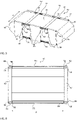
- FIG. 12 shows a prior art representation of a fuel cell stack used in fuel cell system 100 of FIG figure 1 can be arranged.
- the fuel cell stack 10 has a plurality of fuel cells stacked flat on top of one another in the stacking direction S.
- the fuel cell stack 10 In the stacking direction S, the fuel cell stack 10 is delimited by a first end plate 51 and an opposite second end plate 52 . In a first direction transverse to the stacking direction S, the fuel cell stack 10 is delimited by side panels 53, 54. In a second direction transverse to the first direction and transverse to the stacking direction S, the fuel cell stack 10 is delimited by side panels 56 .
- the fuel cell stack 10 shown is compressed via a plurality of a total of five clamping elements 55 .
- Each tensioning element 55 completely runs around a cross section of the fuel cell stack 10 , sweeping over the end plates 51 , 52 and the side panel 56 .
- the clamping elements 55 are located on the end plates 51, 52 and the side panel 56 on.
- Each clamping element 55 is welded to itself in a region of the first end plate 51 .
- the clamping elements 55 are welded to themselves while the clamping elements 55 are under tensile stress.
- a tightening of the clamping elements 55 is in the fuel cell stack 10 according to figure 2 not possible. Instead, as in the figure 3 shown, between the end plate 51 and a compression plate (not shown) of the fuel cell stack 10 of FIG figure 2 a plurality of compression springs 59 are arranged. If the clamping elements 55 lengthen due to aging, this should be compensated for by the compression springs 59 .
- the springs 59 are located in inwardly directed indentations of the end plate 51 . Thus, either additional installation space is required for the springs 59, for example due to a thicker design of the end plate 51, or the end plate 51 must be made thinner in the area of the indentations and is therefore less stable. Both variants lead to specific disadvantages of the respective design.
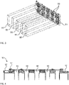
- FIG. 1 shows a schematic representation of a fuel cell stack 10 according to a first embodiment of the present invention.
- figure 6 shows a sectional view of this fuel cell stack 10 along the stacking direction S.
- figure 7 shows a detailed representation of the in figure 5 shown fuel cell stack 10, which will be described below, provided that it differs from the fuel cell stack according to 2 and 3 differs.
- the fuel cell stack 10 has a first end plate 51 and an opposite second end plate 52 .
- Each end plate 51, 52 has an upper and a lower edge area, ie in each case in the area of the transition between the outwardly facing surface of the end plates 51, 52 and an upper and lower surface perpendicular thereto, respectively, a continuous cylindrical cavity.
- Mounting shafts 60 are rotatably mounted in these cavities, for example by suitable bearing shells arranged in the cavities.
- first and second end plates 51, 52 each have two recesses 53 in the upper and lower edge regions.
- the respective mounting shaft 60 is exposed in the recess.
- the end plates 51, 52 in the area of the recesses 53 have a smaller vertical extent (relative to the orientation of the figure 4 ) on.
- the fuel cell stack 10 has two clamping elements 55 which are clamped between the first end plate 51 and the second end plate 52, in particular between an upper edge region of the first end plate 51 and an upper edge region of the second end plate 52.
- the end sections 58 of these clamping elements 55 are respectively fixed to one of the mounting shafts 60.
- the clamping elements 55 have second end portions fixed to the mounting shafts 60 in the edge regions of the second end plate 52 .
- the first end sections 58 are fixed in the area of the recesses 53 of the end plate 51 on the mounting shaft 60 in the upper edge area of the first end plate 51 .
- the second end sections are fixed in an analogous manner in the area of recesses in the second end plate 52 on the mounting shaft 60 there.
- the fuel cell stack 10 has two further clamping elements stretched between the lower edge area of the first end plate 51 and the lower edge area of the second end plate 52 . Of these are in figure 4 only the first end sections 58 are shown, which are fixed in the area of recesses 53 of the lower edge area of the first end plate 51 on the mounting shaft 60 located there.
- the clamping elements 55 can advantageously be wound onto the mounting shafts 60 by rotating them, without the end plates 51, 52 impeding this winding.
- Torsion springs 80 are also fixed within the recesses 53 both on the mounting shaft 60 and on the respective end plate 51, 52.
- the torsion springs 80 are welded to the respective mounting shaft 60 and fastened to an inwardly facing wall of the respective recess 53 by means of a flange (not shown).
- Each end section 58 of each clamping element 55 is surrounded by two torsion springs 80 in each recess 53 .
- An end section 58 of a clamping element 55 and two torsion springs 80 are thus arranged on each section of a mounting shaft 60 that is exposed within a recess 53 .
- the torsion springs 80 are tensioned in such a way that a force exerted by the torsion springs 80 on the assembly shaft 60 or a torque exerted on the assembly shaft 60 opposes a force exerted by the tensioning elements on the assembly shaft 60 or a torque exerted on the assembly shaft 60 .
- a tensioning element 55 that is at least simply wound around the mounting shaft transmits a torque thereto. Due to the rotatable mounting of the assembly shafts 60, there is always a kinematic balance between the torsion springs 80 and the tensioning elements 55.
- the mounting shafts 60 each have an elongate radial groove (not shown).
- the radial groove is designed to receive an end section 58 of one or more clamping elements 55 .
- the end section 58 is then fixed in the radial groove, for example in a materially bonded manner by means of an adhesive. It is also conceivable that the end section 58 has a terminal thickening which corresponds to an internal widening of the radial groove.
- the end section 58 of the clamping element 55 can then be inserted laterally into the assembly shaft 60, that is to say in the direction of the longitudinal extension of the shaft 60, and would thus be positively fixed in the radial groove. It would also be conceivable for the radial groove to be narrowed after the end section 58 has been inserted, for example by placing a snap ring on the shaft 60. This would result in the end section 58 being fixed in the shaft 60 with a force fit.
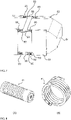
- FIG 8 two preferred embodiments of a torsion spring 80 are shown as milled hollow springs 81 .
- Figure 8 (A) a first torsion spring 80 milled from a hollow cylinder of spring steel. This has an internal thread with which the torsion spring 80 can be screwed onto a mounting shaft 60, the direction of the thread causing the spring 80 to be self-locking on the mounting shaft 60.
- the torsion spring 80 is fixed to the fuel cell stack 10, in particular an inner wall of the recess 53 of an end plate 51, 52, by a non-positive connection of the compressed torsion spring 80 with an end plate 51, 52 and a positive connection of a stop lug that engages in the cutout of the spring 80 end plate 51,52.
- Figure 8 (B) shows a second torsion spring 80 milled from a hollow cylinder of spring steel. This has through bores on both sides at its ends as connection elements for attachment to the mounting shaft 60 or the fuel cell stack 10, in particular an end plate 51, 52.
- the connecting elements are designed as guides for a safety cotter pin.
- FIG. 8 shows a schematic representation of a torsion spring 80 and relevant quantities associated with the torsion spring.
- c denotes the winding ratio, the dimensionless ratio of the mean diameter of the spring D [mm] and the wire thickness t [mm].
- b denotes the width of the wire [mm], M the torque exerted by the spring [Nmm], E the elastic modulus of the spring [MPa], k the torsional spring constant of the spring [Nmm/°], K B a dimensionless curvature correction factor, L K is the active length of the spring [mm], n is the number of active coils, p is the distance between coils [mm], ⁇ is the angular deflection of one end of the spring [°], ⁇ ⁇ is an angle of rest between the ends of the spring [°], and s, a bending stress of the spring material [MPa].
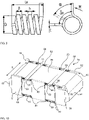
- a fuel cell stack 10 according to another embodiment is disclosed in figure 10 shown. This differs from the first embodiment in that each of the assembly shafts 60 for retensioning the torsion springs 80 has an electric motor 70 which is designed to drive the corresponding assembly shaft 60 by an electric motor, ie to rotate it.
- the electric motors are in figure 10 shown only for the mounting shafts 60 of the end plates 51, 52 located in the upper edge areas.
- the shortening of the clamping elements 55 increases the tensile stress in the clamping element 55 and consequently the tensile force exerted by it and opposed to the spring force of the torsion springs 80 .
- the spring force exerted by the torsion springs 80 also increases as a result of the retensioning of the springs 80.
- the spring force of the springs 80 should always be somewhat stronger when the assembly shafts 60 rotate solidly increase as the tensile stress of the clamping elements 55.
- the fuel cell stack 10 according to FIG figure 10 advantageously allows the torsion springs 80 to be retensioned by means of the electric motors 70.
- the retensioning can advantageously be carried out uniformly by a plurality of electric motors 70.
- these electric motors 70 are controlled by a control unit (not shown), which receives sensor values from at least one tension sensor (not shown), for example a strain gauge or a spring force sensor.
- the electric motors 70 allow automated feedback control of tensile stress transmitted to the stack 10 by means of the clamping elements 55 or the force transmitted by means of the torsion springs 80 to the assembly shafts 60 and thus to the clamping elements 55 fixed therein.
Landscapes
- Life Sciences & Earth Sciences (AREA)
- Engineering & Computer Science (AREA)
- Manufacturing & Machinery (AREA)
- Sustainable Development (AREA)
- Sustainable Energy (AREA)
- Chemical & Material Sciences (AREA)
- Chemical Kinetics & Catalysis (AREA)
- Electrochemistry (AREA)
- General Chemical & Material Sciences (AREA)
- Fuel Cell (AREA)
Description
- Brennstoffzellen nutzen die chemische Umsetzung eines Brennstoffs mit Sauerstoff zu Wasser zum Erzeugen elektrischer Energie. Hierfür weisen Brennstoffzellen eine Membran-Elektroden-Anordnung (MEA - membrane electrode assembly) mit einer Membran-Elektroden-Einheit auf.
- Die Membran-Elektroden-Einheit wird durch eine protonenleitende Membran, PEM, gebildet, an der beidseitig katalytische Elektroden angeordnet sind. Dabei trennt die Membran den der Anode zugeordneten Anodenraum und den der Kathode zugeordneten Kathodenraum voneinander und isoliert diese elektrisch. Auf den nicht der Membran zugewandten Seiten der Elektroden können zudem Gasdiffusionslagen angeordnet sein.
- Im Betrieb der Brennstoffzelle wird ein wasserstoffhaltiger Brennstoff der Anode zugeführt, an der eine elektrochemische Oxidation von H2 zu H+ unter Abgabe von Elektronen erfolgt. Über die elektrolytische Membran erfolgt ein wassergebundener oder wasserfreier Transport der Protonen H+ aus dem Anodenraum in den Kathodenraum. Die an der Anode bereitgestellten Elektronen werden über eine elektrische Leitung der Kathode zugeleitet.
- Der Kathode wird ein sauerstoffhaltiges Betriebsmedium zugeführt, sodass dort eine Reduktion von O2 zu O2 - unter Aufnahme der Elektronen erfolgt. Diese Sauerstoffanionen reagieren im Kathodenraum mit den über die Membran transportierten Protonen unter Bildung von Wasser.
- Ein Brennstoffzellenstapel ist in der Regel durch eine Vielzahl in einem Stapel (stack) in Stapelrichtung übereinander angeordneter MEA gebildet, deren elektrische Leistungen sich addieren. Zwischen den Membran-Elektroden-Anordnungen sind üblicherweise Bipolarplatten angeordnet, die eine Versorgung der einzelnen MEA mit den Reaktanten und einer Kühlflüssigkeit sicherstellen sowie als elektrisch leitfähiger Kontakt zu den Membran-Elektroden-Anordnungen fungieren.
- Zwischen den Membran-Elektroden-Einheiten und den Bipolarplatten sind Dichtungen angeordnet, um die Anoden- und Kathodenräume nach außen abzudichten und ein Austreten der Betriebsmedien aus dem Stapel zu verhindern. Diese Dichtungen sind auf den Membran-Elektroden-Einheiten, den Bipolarplatten oder diesen beiden Komponenten vorgesehen.
- Zum dauerhaften Abdichten des Stapels und zum Gewährleisten des elektrischen Kontakts zwischen Bipolarplatten und Membran-Elektroden-Anordnungen wird der Brennstoffzellenstapel vor der Inbetriebnahme verpresst. Ferner werden Zugelemente eingesetzt, um den Brennstoffzellenstapel auch während des Betriebs zu verpressen.
- Aus dem Stand der Technik sind verschiedene Zugelemente bekannt. Beispielsweise können zwei an den Enden des Brennstoffzellenstapels angeordnete Endplatten mittels Zugelementen verbunden werden. Durch Einleiten von Zugkräften über die Zugelemente in die Endplatten wird der Brennstoffzellenstapel zusammengepresst. Als Zugelemente werden beispielsweise Gewindestäbe, Zuganker, Ketten oder dergleichen eingesetzt.
- Ebenfalls bekannt ist die Verwendung von gespannten streifen- oder bandförmigen elastischen Spannelementen, die entweder mit den Endplatten verbunden sind oder den Stapel in zumindest einem Querschnitt (in Stapelrichtung) zumindest teilweise umlaufen. Hinsichtlich der Ausgestaltung und Befestigungsmöglichkeiten derartiger elastischer Spannelemente (Zugelemente) wird beispielsweise auf die
EP 1 870 952 A2 , dieDE 10 2012 000 266 A1 und dieWO 2012/065890 A1 verwiesen, auf deren Inhalte hiermit vollumfänglich Bezug genommen wird. Ein Nachspannen der elastischen Bandelemente ist dabei jedoch in der Regel nicht vorgesehen. Des Weiteren offenbarenDE 10 2008 026858 A1 ,US 2009/280359 A1 undWO 2011/098276 A1 Brennstoffzellenstapel mit Spannelementen. - Insbesondere in den aktiven Bereichen des Brennstoffzellenstapels beziehungsweise der MEAs kann es zu betriebsbedingten Höhenänderungen kommen, die beispielsweise mit der Temperatur und dem Feuchtegehalt des Brennstoffzellenstapels variieren können. Man spricht auch davon, dass der Stapel atmet. Bei der Verwendung elastischer Spannelemente kann zudem die Elastizität dieser Spannelemente mit der Zeit abnehmen. Insbesondere bei metallischen Spannelementen, die den Brennstoffzellenstapel ringförmig umlaufen und somit mehrere deutliche Knicke aufweisen, kommt es insbesondere im Bereich dieser Umbiegungen zum Längen der Spannelemente. Unabhängig von den Höhenänderungen des Brennstoffzellenstapels und der Alterung der Spannelemente muss stets eine ausreichende Kompression des Stapels gewährleistet werden, insbesondere um die Dichtwirkung der eingesetzten Dichtungen zu garantieren. Aus dem Stand der Technik sind daher bereits Mittel bekannt, mit denen versucht werden soll, die Kompression eines Brennstoffzellenstapels dauerhaft zu gewährleisten.
- Die
DE 10 2010 007 979 A1 offenbart einen Brennstoffzellenstapel mit zwischen zwei Endplatten angeordneten Brennstoffzellen und mindestens einem die Endplatten verbindenden Verspannungsmittel zum Ausüben einer Zugkraft. Zwischen dem Verspannungsmittel und zumindest einer der Endplatten ist ein reibungsminderndes Umlenkmittel angeordnet. Eine Höhenänderung des Stapels soll durch zwischen einer Endplatte und einer Kompressionsplatte angeordnete komprimierte Federelemente ausgeglichen werden. Gemäß diesem Stand der Technik sollen Spannungsspitzen aufgrund der Ausdehnung des Stapels durch elastische Elemente vermieden werden. Ein anfängliches Überspannen der elastischen Elemente soll eine Höhenänderung des Stapels sogar zum Teil vermeiden können. Die elastischen Elemente unterliegen jedoch selbst einer Alterung und zumindest insofern ist diese passive Möglichkeit zur Einstellung der Kompressionskraft nachteilig. - Die
DE 10 2010 007 981 A1 offenbart einen Brennstoffzellenstapel mit zwischen zwei Endplatten angeordneten Brennstoffzellen und mindestens einem die Endplatten verbindenden Verspannungsmittel zum Ausüben einer Zugkraft. Zwischen dem Verspannungsmittel und zumindest einer der Endplatten ist ein Befestigungselement angeordnet, das als Exzenterelement ausgebildet ist oder ein Exzenterelement enthält. Durch Drehen des Befestigungselements soll so ein Abstand zwischen den Endplatten verändert und somit eine Zugkraft zwischen den Endplatten angepasst werden. Das Kompressionssystem gemäß diesem Stand der Technik hat einen komplizierten Aufbau, welches speziell angepasste Endplatten und/oder Verspannungsmittel erfordert und ist nicht für umlaufende Spannelemente geeignet. - Bei ferner bekannten Lösungen mit zwischen den Endplatten und anderen Stapelkomponenten, beispielsweise Kompressionsplatten, angeordneten komprimierten Federelementen, sind in der Regel Vertiefungen in den Endplatten vorgesehen, um die Federelemente aufzunehmen. Hierfür ist zusätzlicher Bauraum im Brennstoffzellenstapel notwendig. Ferner erhöhen die damit verbundenen lokalen Schwächungen der Endplatten deren Neigung zu Deformation und Beschädigung unter einwirkenden Druck- oder Zugkräften.
- Der Erfindung liegt nun die Aufgabe zugrunde, die Nachteile des Standes der Technik zu überwinden und eine Lösung zur dauerhaften Kompression von Brennstoffzellenstapeln bereitzustellen, welche platzsparend in bestehende Brennstoffzellenstapel integrierbar ist und den Erhalt einer Kompressionszugkraft auch über ausgedehnte Zeiträume sicher gewährleistet.
- Diese Aufgabe wird gelöst durch einen Brennstoffzellenstapel mit einer ersten Endplatte und einer zweiten Endplatte und einer Vielzahl von in Stapelrichtung zwischen den zwei Endplatten angeordneten Brennstoffzellen. Ferner weist der Brennstoffzellenstapel zumindest ein in Stapelrichtung zwischen den Endplatten gespanntes elastisches Spannelement auf.
- Der erfindungsgemäße Brennstoffzellenstapel weist ferner zumindest eine drehbare Montagewelle auf. Bevorzugt ist die Montagewelle in den Brennstoffzellenstapel integriert und besonders bevorzugt drehbar in oder an dem Brennstoffzellenstapel gelagert. Erfindungsgemäß ist zumindest ein Endabschnitt, insbesondere ein erster Endabschnitt, von zumindest einem Spannelement an der Montagewelle fixiert. Der Endabschnitt ist bevorzugt kraft-, stoff- und/oder formschlüssig an der Montagewelle fixiert, um Relativbewegungen zwischen Endabschnitt und Montagewelle zu verhindern.
- Erfindungsgemäß ist die drehbare Montagewelle über zumindest eine gespannte Torsionsfeder mit dem Brennstoffzellenstapel verbunden. Mit anderen Worten ist die Torsionsfeder an der Montagewelle und zusätzlich an dem Brennstoffzellenstapel fixiert. Bevorzugt ist ein erstes Ende der Torsionsfeder, beispielsweise ein erstes Ende eines zur Feder gewickelten Drahts, an der Montagewelle und ein zweites Ende der Torsionsfeder, beispielsweise ein zweites Ende des zur Feder gewickelten Drahts, an dem Brennstoffzellenstapel befestigt. Somit wird die Federspannung beziehungsweise das Drehmoment der gespannten Torsionsfeder auf die drehbar gelagerte Montagewelle übertragen. Bevorzugt ist die Torsionsfeder so mit der Montagewelle verbunden, dass ein von der Feder ausgeübtes Drehmoment einer von dem Spannelement ausgeübten Zugspannung entgegengesetzt ist.
- Durch die Fixierung des Endabschnitts zumindest eines Spannelements an der Montagewelle ist die Zugspannung des zumindest einen Spannelements durch eine Drehung der Montagewelle einstellbar. Die Montagewelle erlaubt somit vorteilhaft ein Nachspannen des zumindest einen Spannelements durch Drehen der Montagewelle. Durch die Anordnung der gespannten Torsionsfeder zwischen Montagewelle und Brennstoffzellenstapel wird vorteilhaft ein gerichtetes, der Zugspannung des Spanelements entgegengesetztes Drehmoment auf die Montagewelle übertragen. Vorteilhaft führt die Feder somit bei Nachlassen der Zugspannung des Spannelements, beispielsweise aufgrund von alterungsbedingtem Längen des Spannelements, zum Nachspannen des Spannelements mittels des Drehmoments der Torsionsfeder.
- Der erfindungsgemäße Brennstoffzellenstapel ist somit vorteilhaft dazu ausgestattet, eine Kompression des Brennstoffzellenstapels über die mittels Spannelementen verspannten Endplatten auch über einen ausgedehnten Zeitraum sicher zu gewährleisten. Besonders vorteilhaft erfolgt ein automatisches Nachspannen eines gelängten Spannelements durch Aufwickeln des Spannelements auf die Montagewelle mittels in zumindest einer Torsionsfeder gespeicherter, potentieller Energie. Das Aufwickeln erfolgt dabei nur, wenn die Zugspannung des Spannelements das Drehmoment der Torsionsfeder unterschreitet. Durch Drehen der Montagewelle in eine erste Drehrichtung wird das zumindest eine Spannelement zwischen seinen Endabschnitten effektiv verkürzt und dadurch die von diesem erzeugte Zugkraft erhöht.
- Ferner vorteilhaft ist der erfindungsgemäße Brennstoffzellenstapel dazu ausgebildet, ein Spannelement durch Drehen der Montagewelle in eine entgegengesetzte zweite Drehrichtung wieder von der Montagewelle abzuwickeln. Das Drehen in die zweite Drehrichtung erfolgt dabei in Richtung der Zugspannung des Spannelements und somit entgegen eines von der Torsionsfeder ausgeübten Drehmoments. Das Abwickeln erfolgt somit nur, wenn die Zugspannung das Drehmoment überschreitet. Durch das Drehen in die zweite Drehrichtung wird das Spannelement zwischen seinen Fixpunkten effektiv gelängt und dadurch die von diesem erzeugte Zugkraft verringert. Mit dem erfindungsgemäßen Brennstoffzellenstapel kann somit vorteilhaft verhindert werden, dass eine von den Spannelementen erzeugte Kompressionszugkraft einen bestimmten, durch das Drehmoment der zumindest einen Torsionsfeder bestimmten Grenzwert überschreitet. Somit kann durch Nachlassen der Spannelemente eine Beschädigung von Stapelkomponenten, beispielsweise von porösen Keramiklagen, bei einem betriebsbedingten Anstieg der Stapelhöhe des Brennstoffzellenstapels zuverlässig verhindert werden.
- Bevorzugt ist auch ein zweiter Endabschnitt des zumindest einen Spannelements an dem Brennstoffzellenstapel fixiert. Der zweite Endabschnitt ist dabei verschieden von dem ersten Endabschnitt und jedes Spannelement weist einen ersten und einen zweiten Endabschnitt auf. Der zweite Endabschnitt ist bevorzugt an derselben Montagewelle fixiert, wie der erste Endabschnitt. Ein Drehen der Montagewelle führt somit vorteilhaft zu einer doppelt so starken Verkürzung und somit zur Zugkraftsteigerung im Vergleich zu nur einem befestigten Endabschnitt. Alternativ bevorzugt ist der zweite Endabschnitt des Spannelements an einer weiteren Montagewelle fixiert. Die weitere Montagewelle ist dabei bevorzugt ebenfalls über zumindest eine gespannte Torsionsfeder mit dem Brennstoffzellenstapel verbunden. Somit kann das Spannelement vorteilhaft beidseitig und somit besonders gleichmäßig und exakt nachgespannt werden. Ebenfalls bevorzugt ist der zweite Endabschnitt an einem beliebigen anderen Abschnitt des Brennstoffzellenstapels fest fixiert. Dies stellt eine besonders einfache Ausführungsform der Erfindung dar.
- Bevorzugt ist das elastische Spannelement des Brennstoffzellenstapels im Hook'schen Bereich gespannt. Ein Nachspannen des Spannelements erfolgt bevorzugt in Stapelrichtung (S) des Brennstoffzellenstapels und dabei bevorzugt stets entlang der Spannrichtung der Spannelemente. Besonders bevorzugt ist durch Drehung der Montagewelle die Federkraft der zumindest einen Torsionsfeder und somit die Zugspannung des zumindest einen Spannelements einstellbar. Bevorzugt wird die Stapelkompression durch Anordnung von gespannten Torsionsfedern bestimmter Federkraft auch lokal eingestellt.
- Ebenfalls bevorzugt ist das zumindest eine Spannelement, bevorzugt jedes Spannelement des Brennstoffzellenstapels, über eine Mehrzahl von mit der zumindest einen Montagewelle verbundenen Torsionsfedern gespannt. Dazu ist das zumindest eine Spannelement an einer Montagewelle fixiert und die Mehrzahl gespannter Torsionsfedern an dieser Montagewelle und dem Brennstoffzellenstapel fixiert. So addieren sich die von der Mehrzahl Torsionsfedern aufgebrachten Federkräfte zu einer Gesamtfederkraft. Somit können vorteilhaft auch große durch die Spannelemente erzeugte Kompressionszugspannungen durch die Torsionsfedern gesichert werden.
- In einer bevorzugten Ausführungsform verläuft die zumindest eine Montagewelle entlang eines Kantenbereichs der ersten oder zweiten Endplatte. Der Kantenbereich dieser Endplatte bezeichnet dabei bevorzugt einen Übergang von einer ersten, nach außen weisenden Oberfläche der Endplatte und einer zweiten, zur ersten Oberfläche senkrechten Oberfläche der Endplatte. Die zweite Oberfläche erstreckt sich dabei bevorzugt entlang der Stapelrichtung des Brennstoffzellenstapels beziehungsweise weist einen zur Stapelrichtung senkrechten Normalenvektor auf. In dieser Ausführungsform verlaufen die Spannelemente vorteilhaft nicht über Kanten des Brennstoffzellenstapels hinweg. Gemäß dieser Ausführungsform ist die zumindest eine Montagewelle ferner bevorzugt über die zumindest eine gespannte Torsionsfeder mit der Endplatte verbunden, entlang deren Kantenbereich sie verläuft. Vorteilhaft kommt ein Brennstoffzellenstapel somit durch Hinzufügen entsprechend ausgestatteter Endplatten einfach in den Nutzen der Vorteile der Erfindung.
- Besonders bevorzugt ist die Montagewelle im Bereich eines Kantenbereichs der Endplatte abschnittsweise durch die Endplatte hindurch geführt. Bei einer zylinderförmigen Montagewelle weist die Endplatte in dieser Ausführungsform bevorzugt eine zylinderförmige Bohrung auf. Vorteilhaft ist somit eine einfache drehbare Lagerung der Montagewelle realisierbar. Ferner bevorzugt weist die Endplatte gemäß dieser Ausführungsform Aussparungen beziehungsweise Rücksprünge des Kantenbereichs auf, in denen die Montagewelle freiliegt. Besonders bevorzugt ist das zumindest eine Spannelement im Bereich der Aussparung an der Montagewelle befestigt. Dies erleichtert vorteilhaft das Aufwickeln des Spannelements auf die Montagewelle. Ebenfalls bevorzugt ist die zumindest eine Torsionsfeder in der Aussparung mit der Montagewelle verbunden und ferner bevorzugt mit der Endplatte verbunden.
- In einer ferner bevorzugten Ausführungsform handelt es sich bei der zumindest einen Torsionsfeder um eine Schraubenfeder, besonders bevorzugt um eine aus Draht oder Federstahl spiralig gewickelte Schraubenfeder. Ebenfalls bevorzugt handelt es sich bei der Torsionsfeder um eine Drehstabfeder beziehungsweise einen Torsionsstab. Ferner bevorzugt ist eine solche Drehstabfeder integral mit der Montagewelle ausgebildet, beispielsweise als ein mit dem Brennstoffzellenstapel, bevorzugt einer Endplatte, verbundener Abschnitt der Drehstabfeder. Ebenfalls bevorzugt ist die Torsionsfeder als gefräste Hohlfeder (machined spring) ausgebildet. Dabei ist die Torsionsfeder besonders bevorzugt aus einem Hohlzylinder aus Federstahl gefräst worden.
- Derartige gefräste Hohlfedern ermöglichen vorteilhaft eine besonders exakte Einstellung der Federkraft, insbesondere auch über ausgedehnte Zeiträume.
- Die Verbindung zwischen Torsionsfeder und Montagewelle beziehungsweise Torsionsfeder und Brennstoffzellenstapel ist auf vielfältige Art realisierbar. Beispielsweise ist die Torsionsfeder an den Brennstoffzellenstapel, bevorzugt eine Endplatte, angeflanscht. Auch die Montagewelle kann einen auskragenden Flanschbereich zur Befestigung der Torsionsfeder aufweisen. Alternativ ist die Torsionsfeder unlösbar mit der Montagewelle verbunden, beispielsweise verschweißt. Ferner bevorzugt ist die Torsionsfeder mittels Formschluss, beispielsweise über Bajonett-Anschlusselemente mit dem Brennstoffzellenstapel und/oder der Montagewelle verbunden. Derartige Anschlusselemente sind bevorzugt selbstsichernd ausgebildet, insbesondere unter Berücksichtigung der Wirkrichtung der Federkraft der Torsionsfeder.
- In einer ebenfalls bevorzugten Ausführungsform des erfindungsgemäßen Brennstoffzellenstapels weist die zumindest eine Montagewelle eine längserstreckte Radialnut auf. Diese erstreckt sich bevorzugt parallel zu einer Rotationsachse der Montagewelle. Die Radialnut ist bevorzugt zur Aufnahme des Endabschnitts des zumindest einen Spannelements ausgebildet. Mit anderen Worten wird der Endabschnitt des Spannelements in die Radialnut eingeführt. Ferner bevorzugt wird der Endabschnitt in der Radialnut fixiert, beispielsweise stoffschlüssig, formschlüssig und/oder kraftschlüssig.
- In einer ebenfalls besonders bevorzugten Ausführungsform weist der erfindungsgemäße Brennstoffzellenstapel ferner zumindest einen Elektromotor auf, der zum elektromotorischen Antrieb der zumindest einen Montagewelle ausgebildet ist. Mit anderen Worten ist die zumindest eine Montagewelle mittels eines Elektromotors drehbar. Bevorzugt erlaubt der Motor das Drehen der Montagewelle in einer ersten Drehrichtung und besonders bevorzugt in einer ersten und einer entgegengesetzten zweiten Drehrichtung. Diese Ausführungsform erlaubt vorteilhaft ein automatisiertes Nachspannen der zumindest einen mit der Montagewelle fest verbundenen Torsionsfeder. Somit kann einem altersbedingten Spannungsverlust von den Torsionsfedern selbst entgegen gewirkt werden.
- Besonders bevorzugt weist der Brennstoffzellenstapel zumindest einen Sensor auf, der zum Erfassen einer von zumindest einem Spannelement ausgeübten Zugkraft und/oder der von zumindest einer Torsionsfeder ausgeübten Federkraft ausgebildet ist. Bevorzugt erfasst der Sensor eine auf den gesamten Stapel ausgeübte Kompressionszugkraft und ist hierfür beispielsweise als Sensorzelle zwischen den gestapelten Brennstoffzellen angeordnet. Alternativ bevorzugt erfasst der Sensor die von einem bestimmten Spannelement ausgeübte Zugkraft und/oder die von einer bestimmten Torsionsfeder ausgeübten Federkraft. Beispielsweise ist ein solcher Sensor als Dehnungsmessstreifen ausgebildet. Besonders bevorzugt ist ein Sensor, insbesondere ein Dehnungsmessstreifen, an jedem Spannelement angeordnet.
- Die Verwendung solcher Sensoren im erfindungsgemäßen Brennstoffzellenstapel ermöglicht vorteilhaft das Messen von kollektiven oder individuellen Längenänderungen der Spannelemente. Anhand der Längenänderung des Spannelements wird bevorzugt eine Zugkraft beziehungsweise Zugkraftänderung des jeweiligen Spannelements ermittelt. Daraus lassen sich Rückschlüsse ziehen, dass eine oder mehrere Torsionsfedern zum Ausgleich des Zugspannungsverlusts nicht mehr ausreichend gespannt sind. Durch Nachspannen der Federn können diese erneut einer Zugkraftänderung des zumindest einen Spannelementes entgegen wirken. Auch anhand von Messwerten von Sensoren zum Erfassen der von einer Torsionsfeder ausgeübten Federkraft kann ermittelt werden, ob diese Feder nachspannt werden muss.
- Ferner bevorzugt weist der erfindungsgemäße Brennstoffzellenstapel zumindest eine Steuereinheit auf, die mit dem zumindest einen Sensor verbunden und zum Betrieb des zumindest einen Elektromotors ausgebildet ist. Die Steuereinheit ist bevorzugt zum Empfang eines Sensorsignals von dem zumindest einem Sensor ausgebildet. Ferner ist die Steuereinheit zur Ausgabe eines Steuersignals an den zumindest einen Elektromotor ausgebildet. Die Ausführungsform ermöglicht vorteilhaft ein automatisiertes Nachspannen der Torsionsfedern anhand von Sensorwerten zur Zugkraft der Spannelemente und/oder anhand von Sensorwerten zur Zugkraft der Torsionsfedern.
- In einer besonders bevorzugten Ausführungsform weist der Brennstoffzellenstapel eine Mehrzahl von Spannelementen und eine Mehrzahl von Montagewellen auf. Jede Montagewelle ist dabei mit ein oder mehreren gespannten Torsionsfedern mit dem Brennstoffzellenstapel verbunden und an jeder Montagewelle sind ein oder mehrere Spannelemente fixiert. Ferner bevorzugt weist der Brennstoffzellenstapel eine Mehrzahl von zum Antrieb zumindest einer der Montagewellen ausgebildeten Elektromotoren auf.
- Diese Ausführungsform ermöglicht eine Zugspannungskontrolle von individuellen Gruppen von Spannelementen oder sogar von einzelnen Spannelementen. Wesentlich dafür ist, dass verschiedene Spannelemente an verschiedenen Montagewellen fixiert sind. Das Drehen der Montagewellen erfolgt bevorzugt durch einen gemeinsamen Elektromotor. Beispielsweise können zwei Montagewellen von einem mittig zwischen diesen Wellen angeordneten Motor betrieben werden. Ebenfalls bevorzugt sind mehrere Spannelemente über jeweilige Kupplungen steuerbar kraftschlüssig mit einem gemeinsamen Motor verbunden. Der Brennstoffzellenstapel dieser Ausführungsform weist ferner bevorzugt eine Mehrzahl von zum Messen der Zugspannung der Spannelemente eingerichtete Sensoren auf.
- Ferner bevorzugt weist die zumindest eine Montagewelle zumindest ein Sperrrad und zumindest eine mit dem Sperrrad in Eingriff stehende Sperrklinke auf. Bevorzugt wird somit das Prinzip einer Ratsche genutzt, um eine Drehung der Montagewelle nur in eine Richtung zu gestatten. Somit können die Torsionsfedern entlastet und die Lager der Elektromotoren geschont werden. Diese Ausführungsform ist vorteilhaft mit dem Einsatz eines einzelnen Motors für eine Mehrzahl von Montagewellen kombinierbar.
- In einer ebenfalls bevorzugten Ausführungsform des erfindungsgemäßen Brennstoffzellenstapels ist zumindest eine von der ersten Endplatte und der zweiten Endplatte segmentiert ausgebildet. Bevorzugt verläuft über jedes dieser Segmente zumindest ein Spannelement. Besonders bevorzugt weist jedes Endplattensegment eine individuelle Montagewelle auf, die unabhängig von den anderen Montagewellen über zumindest eine Torsionsfeder mit dem Brennstoffzellenstapel, bevorzugt dem jeweiligen Endplattensegment, verbunden ist. Die dadurch bewirkte Entkopplung der einzelnen Spannelemente ermöglicht vorteilhaft eine lokale Variation der Stapelkompression.
- Bei dem Spannelement handelt es sich bevorzugt um ein aus dem Stand der Technik bekanntes elastisches Spannelement, welches jeweils an den Endplatten des Brennstoffzellenstapels befestigt ist oder den Brennstoffzellenstapel in zumindest einem Querschnitt entlang der Stapelrichtung im Wesentlichen vollständig (mit anderen Worten ringförmig) umläuft.
- Das Spannelement liegt vorzugsweise zumindest abschnittsweise flächig an einer Oberfläche des Brennstoffzellenstapels an. Alternativ ist das Spannelement zumindest abschnittsweise vom Brennstoffzellenstapel beabstandet. Beispielsweise stehen die Endplatten in lateraler Richtung über die Brennstoffzellen über, so dass das Spannelement einen Abstand zu den Seitenwänden der Brennstoffzellen aufweist. Alternativ werden auf den Endplatten montierte Abstandshalter genutzt, um einen Abstand zwischen einem oder mehreren Spannelementen und einer oder beiden Endplatten zu realisieren.
- Das Spannelement ist bevorzugt als band- oder streifenförmiges flexibles und/oder elastisches Spannelement ausgebildet, wie beispielsweise aus der
EP 1 870 952 A2 bekannt. Das Spannelement besteht bevorzugt aus einem elastischen Kunststoff, einem elastischen Polymer (z.B. Nylon) oder einem elastischen Metall, und weist bei Standardbedingungen ein Elastizitätsmodul > 1 GPa und besonders bevorzugt > 5 GPa entlang der Spannrichtung auf. - Ein Endabschnitt des Spannelements ist ferner bevorzugt stoffschlüssig und/oder mittels mindestens eines Spannmittels an einer Stapelendplatte fixiert. Um eine einfache Demontage des Brennstoffzellenstapels zu gewährleisten, ist das Spannelement bevorzugt an mindestens einer Endplatte des Stapels lösbar fixiert. Besonders bevorzugt ist das Spannelement an der Endplatte eingehängt. Hierfür weist die Endplatte bevorzugt zumindest einen Einhängehaken zum Einhängen des Spannelements an einer seiner Seitenflächen oder auf seiner in Stapelrichtung nach außen weisenden Oberfläche auf. Ebenfalls bevorzugt weist das Spannelement mindestens eine Einhängeöffnung zum Einhängen an einem Einhängehaken auf. Der andere Endabschnitt des Spannelements ist dann an der Montagewelle fixiert.
- Alternativ erstreckt sich das zumindest eine Spannelement in einem Querschnitt in Stapelrichtung zumindest im Wesentlichen um einen Umfang des Brennstoffzellenstapels. Dabei ist ein Spannelement an mindestens einem seiner Endbereiche an einem anderen Endbereich desselben Spannelements oder an einem anderen Spannelement fixiert. Das Spannelement kann also ringförmig geschlossen ausgebildet sein. Dabei stoßen die Endabschnitte nicht stumpf aufeinander, sondern verlaufen abschnittsweise parallel entlang einander, so dass beide Endabschnitte in dieselbe Richtung weisen. Die so verbundenen Endabschnitte sind dann gemeinsam an einer Montagewelle fixiert und ermöglichen ein besonders effizientes Auf- und Abwickeln.
- In einer ebenfalls bevorzugten Ausführungsform ist ein Umlenkmittel in zumindest einem von dem zumindest einen Spannelement überspannten Kantenbereich des Brennstoffzellenstapels angeordnet. Besonders bevorzugt ist ein Umlenkmittel in zumindest einem von dem zumindest einen Spannelement überspannten Kantenbereich der ersten Endplatte und/oder der zweiten Endplatte angeordnet. Das Umlenkmittel ist insbesondere dazu ausgebildet, eine Reibung zwischen dem Spannelement und dem Kantenbereich zu verringern. Diese Reibungsverminderung ermöglicht vorteilhaft eine wiederholte und fein justierbare Einstellbarkeit der Stapelspannung über den veränderbar fixierbaren Abstand zwischen Nachspannelement und Stapel.
- Bei dem Umlenkmittel handelt es sich bevorzugt um eine gleitreibungsarme Oberfläche, beispielsweise durch eine entsprechende Beschichtung. Ebenfalls bevorzugt handelt es sich bei dem Umlenkmittel um eine Umlenkrolle. Ebenfalls bevorzugt ist das Umlenkmittel in zumindest einer der Endplatten angeordnet. Für weitere Details zur Ausgestaltung der Umlenkmittel wird hiermit vollumfänglich auf die
DE 10 2010 007 979 A1 Bezug genommen. - Besonders bevorzugt sind alle Kantenbereiche der Endplatten mit Umlenkrollen versehen, wobei zumindest einige davon als Montagewelle mit Mitteln zum Fixieren eines Endabschnitts eines Spannelements ausgestattet sind. Bevorzugt sind zumindest diese Umlenkrollen (Montagewellen) über gespannte Torsionsfedern mit dem Brennstoffzellenstapel verbunden.
- Ebenfalls Gegenstand der Erfindung ist ein Fahrzeug, insbesondere ein elektromotorisch betriebenes Fahrzeug mit einem erfindungsgemäßen Brennstoffzellenstapel, wie vorstehend beschrieben. Der Brennstoffzellenstapel dient dabei insbesondere dem Speisen eines Elektromotors des Fahrzeugs.
- Weitere bevorzugte Ausgestaltungen der Erfindung ergeben sich aus den übrigen, in den Unteransprüchen genannten Merkmalen. Die verschiedenen in dieser Anmeldung genannten Ausführungsformen der Erfindung sind, sofern im Einzelfall nicht anders erläutert, mit Vorteil miteinander kombinierbar.
- Die Erfindung wird nachfolgend in Ausführungsbeispielen anhand der zugehörigen Zeichnungen erläutert. Es zeigen:
- Figur 1
- eine schematische Darstellung eines Brennstoffzellensystems gemäß dem Stand der Technik;
- Figur 2
- einen Brennstoffzellenstapel mit einer Mehrzahl den Stapel komprimierender Spannelemente gemäß dem Stand der Technik;
- Figur 3
- eine Detaildarstellung des Brennstoffzellenstapels gemäß
Fig.2 ; - Figur 4
- eine Detaildarstellung des Brennstoffzellenstapels gemäß
Fig.2 ; - Figur 5
- einen Brennstoffzellenstapel gemäß einer Ausführungsform;
- Figur 6
- eine Schnittdarstellung des Brennstoffzellenstapels der
Fig. 5 ; - Figur 7
- eine Detaildarstellung des Brennstoffzellenstapels der
Fig. 5 ; - Figur 8
- zwei Varianten gefräster Hohlfedern;
- Figur 9
- eine schematische Darstellung relevanter Größen einer Torsionsfeder; und
- Figur 10
- einen Brennstoffzellenstapel gemäß einer alternativen Ausführungsform.
-
Figur 1 zeigt ein insgesamt mit 100 bezeichnetes Brennstoffzellensystem gemäß dem Stand der Technik. Das Brennstoffzellensystem 100 ist Teil eines nicht weiter dargestellten Fahrzeugs, insbesondere eines Elektrofahrzeugs, das einen Elektrotraktionsmotor aufweist, der durch das Brennstoffzellensystem 100 mit elektrischer Energie versorgt wird. - Das Brennstoffzellensystem 100 umfasst als Kernkomponente einen Brennstoffzellenstapel 10, der eine Vielzahl von in Stapelform angeordneten Einzelzellen 11 aufweist, die durch abwechselnd gestapelte Membran-Elektroden-Anordnungen (MEA) 14 und Bipolarplatten 15 ausgebildet werden (siehe Detailausschnitt). Jede Einzelzelle 11 umfasst somit jeweils eine MEA 14 mit einer hier nicht näher dargestellten ionenleitfähigen Polymerelektrolytmembran sowie beidseits daran angeordneten katalytischen Elektroden. Diese Elektroden katalysieren die jeweilige Teilreaktion der Brennstoffumsetzung. Die Anoden- und Kathodenelektrode sind als Beschichtung auf der Membran ausgebildet und weisen ein katalytisches Material auf, beispielsweise Platin, das auf einem elektrisch leitfähigen Trägermaterial großer spezifischer Oberfläche, beispielsweise einem kohlenstoffbasierten Material, geträgert vorliegt.
- Wie in der Detaildarstellung der
Figur 1 gezeigt, ist zwischen einer Bipolarplatte 15 und der Anode ein Anodenraum 12 ausgebildet und zwischen der Kathode und der nächsten Bipolarplatte 15 der Kathodenraum 13 ausgebildet. Die Bipolarplatten 15 dienen der Zuführung der Betriebsmittel in die Anoden- und Kathodenräume 12, 13 und stellen ferner die elektrische Verbindung zwischen den einzelnen Brennstoffzellen 11 her. Optional können Gasdiffusionslagen zwischen den Membran-Elektroden-Anordnungen 14 und den Bipolarplatten 15 angeordnet sein. - Um den Brennstoffzellenstapel 10 mit den Betriebsmitteln zu versorgen, weist das Brennstoffzellensystem 100 einerseits eine Anodenversorgung 20 und andererseits eine Kathodenversorgung 30 auf.
- Die Anodenversorgung 20 des in
Figur 1 gezeigten Brennstoffzellensystems 100 umfasst einen Anodenversorgungspfad 21, welcher der Zuführung eines Anodenbetriebsmittels (dem Brennstoff), beispielsweise Wasserstoff, in die Anodenräume 12 des Brennstoffzellenstapels 10 dient. Zu diesem Zweck verbindet der Anodenversorgungspfad 21 einen Brennstoffspeicher 23 mit einem Anodeneinlass des Brennstoffzellenstapels 10. Das Einstellen des Einspeisedrucks des Anodenbetriebsmediums in die Anodenräume 12 des Brennstoffzellenstapels 10 erfolgt über ein Dosierventil 27.1. Die Anodenversorgung 20 umfasst ferner einen Anodenabgaspfad 22, der das Anodenabgas aus den Anodenräumen 12 über einen Anodenauslass des Brennstoffzellenstapels 10 abführt. - Darüber hinaus weist die Anodenversorgung 20 des in
Figur 1 gezeigten Brennstoffzellensystems 100 eine Rezirkulationsleitung 24 auf, welche den Anodenabgaspfad 22 mit dem Anodenversorgungspfad 21 verbindet. Die Rezirkulation von Brennstoff ist üblich, um den überstöchiometrisch eingesetzten Brennstoff dem Brennstoffzellenstapel 10 zurückzuführen. In der Rezirkulationsleitung 24 sind eine Rezirkulationsfördereinrichtung 25, vorzugsweise ein Rezirkulationsgebläse, sowie ein Klappenventil 27.2 angeordnet. - In der Anodenversorgung 22 des Brennstoffzellensystems ist ferner ein Wasserabscheider 26 verbaut, um das aus der Brennstoffzellenreaktion entstehende Produktwasser abzuleiten. Ein Ablass des Wasserabscheiders kann mit der Kathodenabgasleitung 32, einem Wassertank oder einer Abgasanlage verbunden sein.
- Die Kathodenversorgung 30 des in
Figur 1 gezeigten Brennstoffzellensystems 100 umfasst einen Kathodenversorgungspfad 31, welcher den Kathodenräumen 13 des Brennstoffzellenstapels 10 ein sauerstoffhaltiges Kathodenbetriebsmittel zuführt, insbesondere Luft, die aus der Umgebung angesaugt wird. Die Kathodenversorgung 30 umfasst ferner einen Kathodenabgaspfad 32, welcher das Kathodenabgas (insbesondere die Abluft) aus den Kathodenräumen 13 des Brennstoffzellenstapels 10 abführt und dieses gegebenenfalls einer nicht dargestellten Abgasanlage zuführt. - Zur Förderung und Verdichtung des Kathodenbetriebsmittels ist in dem Kathodenversorgungspfad 31 ein Verdichter 33 angeordnet. In dem dargestellten Ausführungsbeispiel ist der Verdichter 33 als ein hauptsächlich elektromotorisch angetriebener Verdichter 33 ausgestaltet, dessen Antrieb über einen mit einer entsprechenden Leistungselektronik 35 ausgestatteten Elektromotor 34 erfolgt.
- Das in
Figur 1 gezeigte Brennstoffzellensystem 100 weist ferner ein stromaufwärts des Verdichters 33 in der Kathodenversorgungsleitung 31 angeordnetes Befeuchtermodul 39 auf. Das Befeuchtermodul 39 ist einerseits so in dem Kathodenversorgungspfad 31 angeordnet, dass es von dem Kathodenbetriebsgas durchströmbar ist. Andererseits ist es so in dem Kathodenabgaspfad 32 angeordnet, dass es von dem Kathodenabgas durchströmbar ist. Ein Befeuchter 39 weist typischerweise eine Mehrzahl von wasserdampfpermeablen Membranen auf, die entweder flächig oder in Form von Hohlfasern ausgebildet sind. Dabei wird eine Seite der Membranen von dem vergleichsweise trockenen Kathodenbetriebsgas (Luft) überströmt und die andere Seite von dem vergleichsweise feuchten Kathodenabgas (Abgas). Getrieben durch den höheren Partialdruck an Wasserdampf in dem Kathodenabgas kommt es zu einem Übertritt von Wasserdampf über die Membran in das Kathodenbetriebsgas, das auf diese Weise befeuchtet wird. - Das Brennstoffzellensystem 100 weist ferner einen die Kathodenversorgungsleitung stromaufwärts und stromabwärts des Befeuchters 39 miteinander verbindenden Befeuchterbypass 37 mit einem darin angeordneten Klappenventil als Bypassstellmittel 38 auf. Ferner sind Klappenventile 27.3 und 27.4 stromaufwärts des Brennstoffzellenstapels 10 in der Anodenversorgungsleitung 31 beziehungsweise stromabwärts des Brennstoffzellenstapels 10 in der Anodenabgasleitung 32 angeordnet.
- Verschiedene weitere Einzelheiten der Anoden- und Kathodenversorgung 20, 30 sind in
Figur 1 aus Gründen der Übersichtlichkeit nicht gezeigt. Beispielsweise kann die Anodenabgasleitung 22 in die Kathodenabgasleitung 32 münden, sodass das Anodenabgas und das Kathodenabgas über eine gemeinsame Abgasanlage abgeführt werden. - Die
Figur 2 zeigt eine Darstellung eines Brennstoffzellenstapels gemäß dem Stand der Technik, der im Brennstoffzellensystem 100 derFigur 1 angeordnet sein kann. Der Brennstoffzellenstapel 10 weist eine Mehrzahl von in Stapelrichtung S flächig aufeinander gestapelten Brennstoffzellen auf. - In Stapelrichtung S ist der Brennstoffzellenstapel 10 von einer ersten Endplatte 51 und einer gegenüberliegenden zweiten Endplatte 52 begrenzt. In einer ersten Richtung quer zur Stapelrichtung S ist der Brennstoffzellenstapel 10 durch Seitenverkleidungen 53, 54 begrenzt. In einer zweiten Richtung quer zur ersten Richtung und quer zur Stapelrichtung S ist der Brennstoffzellenstapel 10 durch Seitenverkleidung 56 begrenzt.
- Der in
Figur 2 gezeigte Brennstoffzellenstapel 10 ist über eine Mehrzahl von insgesamt fünf Spannelementen 55 komprimiert. Jedes Spannelement 55 umläuft dabei einen Querschnitt des Brennstoffzellenstapels 10 vollständig, wobei es die Endplatten 51, 52 sowie die Seitenverkleidung 56 überstreicht. Die Spannelemente 55 liegen dabei an den Endplatten 51, 52 und der Seitenverkleidung 56 an. Jedes Spannelement 55 ist in einem Bereich der ersten Endplatte 51 mit sich selbst verschweißt. Zum Komprimieren des Brennstoffzellenstapels 10 erfolgt das Verschweißen der Spannelemente 55 mit sich selbst, während die Spannelemente 55 unter Zugspannung stehen. - Ein Nachspannen der Spannelemente 55 ist bei dem Brennstoffzellenstapel 10 gemäß der
Figur 2 nicht möglich. Stattdessen sind, wie in derFigur 3 dargestellt, zwischen der Endplatte 51 und einer Kompressionsplatte (nicht dargestellt) des Brennstoffzellenstapels 10 derFigur 2 eine Mehrzahl von Kompressionsfedern 59 angeordnet. Kommt es zu einem alterungsbedingten Längen der Spannelemente 55, soll dies durch die Kompressionsfedern 59 ausgeglichen werden. Die Federn 59 sind in nach innen weisenden Vertiefungen der Endplatte 51 angeordnet. Somit ist entweder zusätzlicher Bauraum für die Federn 59 notwendig, beispielsweise durch eine dickere Ausführung der Endplatte 51, oder die Endplatte 51 muss im Bereich der Vertiefungen dünner ausgebildet werden und ist somit instabiler. Beide Varianten führen zu spezifischen Nachteilen des jeweiligen Designs. Wie inFigur 4 dargestellt, ist aufgrund der Verwendung umlaufender Spannelemente 55 ein Spannen der Endplatte 51 in den Einlass-/Auslassebereichen 57 des Brennstoffzellenstapels 10, in denen die Betriebsmedien zu- beziehungsweise abgeführt werden, nicht möglich. Somit kommt es im Stand der Technik nachteilig zu einem Aufbiegen der Endplatten 51 und zu ungleicher Kompression. -
Figur 5 zeigt eine schematische Darstellung eines Brennstoffzellenstapels 10 gemäß einer ersten Ausführungsform der vorliegenden Erfindung.Figur 6 zeigt eine Schnittdarstellung dieses Brennstoffzellenstapels 10 entlang der Stapelrichtung S.Figur 7 zeigt eine Detaildarstellung des inFigur 5 gezeigten Brennstoffzellenstapels 10, der im Folgenden beschrieben wird, sofern er sich von dem Brennstoffzellenstapel gemäß denFig. 2 und3 unterscheidet. - Der Brennstoffzellenstapel 10 weist eine erste Endplatte 51 sowie eine gegenüberliegende zweite Endplatte 52 auf. Jede Endplatte 51, 52 weist jeweils in einem oberen und in einem unteren Kantenbereich, das heißt jeweils im Bereich des Übergangs zwischen der nach außen weisenden Oberfläche der Endplatten 51, 52 und einer oberen beziehungsweise unteren senkrecht dazu stehenden Oberfläche, einen durchgehenden zylindrischen Hohlraum auf. In diesen Hohlräumen sind Montagewellen 60 drehbar gelagert, beispielsweise durch in den Hohlräumen angeordnete, geeignete Lagerschalen.
- Ferner weist die erste und zweite Endplatte 51, 52 jeweils zwei Aussparungen 53 in dem oberen und dem unteren Kantenbereich auf. In der Aussparung liegt die jeweilige Montagewelle 60 frei. Mit anderen Worten weisen die Endplatten 51, 52 im Bereich der Aussparungen 53 eine geringere vertikale Ausdehnung (bezogen auf die Ausrichtung der
Figur 4 ) auf. - Der Brennstoffzellenstapel 10 weist zwei Spannelemente 55 auf, die zwischen der ersten Endplatte 51 und der zweiten Endplatte 52 gespannt sind, insbesondere zwischen einem oberen Kantenbereich der ersten Endplatte 51 und einem oberen Kantenbereich der zweiten Endplatte 52. Dabei sind die Endabschnitte 58 dieser Spannelemente 55 jeweils an einer der Montagewellen 60 fixiert. In
Figur 4 sind nur die an den Montagewellen 60 der ersten Endplatte 51 fixierten ersten Endabschnitte 58 explizit bezeichnet. Nichtsdestotrotz weisen die Spannelemente 55 zweite, an den Montagewellen 60 in den Kantenbereichen der zweiten Endplatte 52 fixierte Endabschnitte auf. - Die ersten Endabschnitte 58 sind dabei im Bereich der Aussparungen 53 der Endplatte 51 an der Montagewelle 60 im oberen Kantenbereich der ersten Endplatte 51 fixiert. Die zweiten Endabschnitte sind in analoger Weise im Bereich von Aussparungen der zweiten Endplatte 52 an der dortigen Montagewelle 60 fixiert. Der Brennstoffzellenstapel 10 weist zwei weitere, zwischen dem unteren Kantenbereich der ersten Endplatte 51 und dem unteren Kantenbereich der zweiten Endplatte 52 gespannte Spannelemente auf. Von diesen sind in
Figur 4 lediglich die ersten Endabschnitte 58 dargestellt, die im Bereich von Aussparungen 53 des unteren Kantenbereichs der ersten Endplatte 51 an der dort befindlichen Montagewelle 60 fixiert sind. - Durch das Fixieren, das heißt stoff-, kraft-, und/oder formschlüssiges Befestigen der ersten Endabschnitte 58 und der zweiten Endabschnitte der Spannelemente 55 an den Montagewellen 60 im Bereich von Aussparungen 53 der Endplatten 51, 52 können die Spannelemente 55 durch Drehen der Montagewellen 60 vorteilhaft auf diese aufgewickelt werden, ohne dass die Endplatten 51 ,52 dieses Aufwickeln behindern würden.
- Innerhalb der Aussparungen 53 sind ferner Torsionsfedern 80 sowohl an der Montagewelle 60 als auch an der jeweiligen Endplatte 51, 52 fixiert. Insbesondere sind die Torsionsfedern 80 mit der jeweiligen Montagewelle 60 verschweißt und mittels eines Flanschs (nicht dargestellt) an einer nach innen weisenden Wandung der jeweiligen Aussparung 53 befestigt. Dabei ist jeder Endabschnitt 58 jedes Spannelements 55 in jeder Aussparung 53 von jeweils zwei Torsionsfedern 80 umgeben. Auf jedem innerhalb einer Aussparung 53 freiliegenden Abschnitt einer Montagewelle 60 sind somit ein Endabschnitt 58 eines Spannelements 55 und zwei Torsionsfedern 80 angeordnet.
- Die Torsionsfedern 80 sind so gespannt, dass eine von den Torsionsfedern 80 auf die Montagewelle 60 ausgeübte Kraft beziehungsweise ein auf die Montagewelle 60 ausgeübtes Drehmoment einer von den Spannelementen auf die Montagewelle 60 ausgeübten Kraft beziehungsweise einem auf die Montagewelle 60 ausgeübtes Drehmoment entgegengesetzt sind. Dabei überträgt insbesondere ein zumindest einfach um die Montagewelle gewickeltes Spannelement 55 ein Drehmoment darauf. Aufgrund der drehbaren Lagerung der Montagewellen 60 besteht stets ein kinematisches Gleichgewicht zwischen den Torsionsfedern 80 und den Spannelementen 55. Somit wird ein Nachlassen der Zugspannung der Spannelemente 55, beispielsweise durch ein alterungsbedingtes Längen, durch ein Aufwickeln der Spannelemente 55 auf die Montagewellen 60, welches durch das Drehmoment der Torsionsfedern 80 bewirkt wird, ausgeglichen. Somit ist ein Erhalt der Zugspannung der Spannelemente 55 und somit der auf den Stapel 10 wirkenden Kompressionszugkraft auch über ausgedehnte Zeiträume sichergestellt.
- Bevorzugt weisen die Montagewellen 60 jeweils eine längserstreckte Radialnut (nicht dargestellt) auf. Mit anderen Worten ist entlang einer Längsausdehnung der Montagewelle 60 eine Nut in radialer Richtung in die Montagewelle 60 eingebracht. Die Radialnut ist dabei dafür ausgebildet, einen Endabschnitt 58 eines oder mehrerer Spannelemente 55 aufzunehmen. Der Endabschnitt 58 wird daraufhin in der Radialnut fixiert, beispielsweise stoffschlüssig mittels eines Klebstoffs. Ebenso denkbar ist, dass der Endabschnitt 58 eine endständige Verdickung aufweist, die mit einer innenliegenden Aufweitung der Radialnut korrespondiert. Der Endabschnitt 58 des Spannelements 55 kann dann seitlich in die Montagewelle 60 eingeführt werden, das heißt in Richtung der Längsausdehnung der Welle 60, und wäre somit formschlüssig in der Radialnut fixiert. Ebenso denkbar wäre, dass die Radialnut nach Einführen des Endabschnitts 58 verengt wird, beispielsweise durch Aufsetzen eines Sprengrings auf die Welle 60. Dies hätte eine kraftschlüssige Fixierung des Endabschnitts 58 in der Welle 60 zur Folge.
- In
Figur 8 sind zwei bevorzugte Ausführungsformen einer Torsionsfeder 80 als gefräste Hohlfedern 81 dargestellt. Dabei zeigtFigur 8 (A) eine erste aus einem Hohlzylinder Federstahl gefrästen Torsionsfeder 80. Diese weist ein Innengewinde auf, mit dem die Torsionsfeder 80 auf eine Montagewelle 60 aufgeschraubt werden kann, wobei die Gewinderichtung eine Selbstsicherung der Feder 80 auf der Montagewelle 60 bewirkt. Eine Fixierung der Torsionsfeder 80 am Brennstoffzellenstapel 10, insbesondere einer Innenwandung der Aussparung 53 einer Endplatte 51, 52 erfolgt im einfachsten Fall durch einen Kraftschluss der komprimierten Torsionsfeder 80 mit einer Endplatte 51, 52 und einem Formschluss einer in die Ausfräsung der Feder 80 eingreifenden Anschlagsnase der Endplatte 51 ,52.Figur 8 (B) zeigt eine zweite aus einem Hohlzylinder Federstahl gefrästen Torsionsfeder 80. Diese weist beidseitig an ihren Enden Durchgangsbohrungen als Anschlusselemente für eine Befestigung an der Montagewelle 60 beziehungsweise dem Brennstoffzellenstapel 10, insbesondere einer Endplatte 51, 52, auf. Die Anschlusselemente sind als Führung für einen Sicherungssplint ausgebildet. -
Figur 9 zeigt eine schematische Darstellung einer Torsionsfeder 80 sowie mit der Torsionsfeder zusammenhängender relevanter Größen. - Dabei bezeichnet c das Wicklungsverhältnis das dimensionslose Verhältnis aus mittlerem Durchmesser der Feder D [mm] und der Drahtstärke t [mm]. Ferner bezeichnet b die Breite des Drahtes [mm], M das von der Feder ausgeübte Drehmoment [Nmm], E das Elastizitätsmodul der Feder [MPa], k die Torsionsfederkonstante der Feder [Nmm/°], KB einen dimensionslosen Krümmungskorrekturfaktor, LK die aktive Länge der Feder [mm], n die Nummer der aktiven Wicklungen, p den Abstand zwischen den Wicklungen [mm], α die Winkelauslenkung eines Endes der Feder [°], δο einen Ruhewinkel zwischen den Enden der Feder [°], und s eine Biegebeanspruchung des Federmaterials [MPa].
- Mit den in Tabelle 1 angegebenen Formeln für aus Draht mit rechteckigem Querschnitt gewickelte Schraubenfedern ergibt sich, dass mit 8 Federn, wobei jede Feder jeweils einen mittleren Durchmesser D = 30 mm, zehn Wicklungen (n = 10), ein Elastizitätsmodul E = 200 Gpa, eine Drahtbreite b = 10 mm und eine Drahtdicke t = 6 mm aufweist, eine Winkelverdrehung von ca. 14° ausreichend ist, um eine Kraft von 5000 N aufzubringen. Für ein diese Zugkraft aufbringendes Spannelement 55 wäre es somit ausreichend, wenn auf jeder Montagewelle 60 auf jeder Seite des Endabschnitts 58 jeweils zwei solche Federn fest mit der Montagewelle 60 und einem Fixpunkt des Brennstoffzellenstapels 10 (unbewegliches Ende) verbunden sind. Mit einer solchen Konfiguration, ließe sich die Zugkraft des Spannelements 55 von 5000 N für einen ausgedehnten Zeitraum gewährleisten.
Tabelle 1 


- Ein Brennstoffzellenstapel 10 gemäß einer weiteren Ausführungsform ist in
Figur 10 gezeigt. Diese unterscheidet sich von der ersten Ausführungsform dadurch, dass jede der Montagewellen 60 zum Nachspannen der Torsionsfedern 80 einen Elektromotor 70 aufweist, der zum elektromotorischen Antrieb, das heißt zum Drehen, der entsprechenden Montagewelle 60 ausgebildet ist. Die Elektromotoren sind inFigur 10 nur für die in den oberen Kantenbereichen befindlichen Montagewellen 60 der Endplatten 51, 52 dargestellt. - Wie anhand der Darstellung der
Figuren 6 und10 ersichtlich, führt ein Nachspannen der mit den Montagewellen 60 fest verbundenen Torsionsfedern 80 durch Drehen der Montagewellen 60 unweigerlich auch zu einem Aufwickeln des zwischen der ersten Endplatte 51 und der zweiten Endplatte 52 gespannten Spannelements 55 auf eine der Montagewellen 60, beispielsweise auf die durch Elektromotor 70 betriebene Montagewelle 60 der ersten Endplatte 51, und somit unweigerlich auch zu einer Verkürzung des Spannelements 55 im Bereich zwischen den Endabschnitten 58. - Durch das Verkürzen der Spannelemente 55 steigt die Zugspannung in dem Spannelement 55 und folglich die von diesem ausgeübte und der Federkraft der Torsionsfedern 80 entgegengesetzte Zugkraft. Gleichzeitig steigt auch die von den Torsionsfedern 80 ausgeübte Federkraft durch Nachspannen der Federn 80. Um effektiv ein Nachspannen der Torsionsfedern 80, das heißt eine stärkere Sicherung der Spannelemente zu erreichen, sollte bei einer festen Umdrehung der Montagewellen 60 die Federkraft der Federn 80 stets etwas stärker zunehmen als die Zugspannung der Spannelemente 55.
- Der Brennstoffzellenstapel 10 gemäß
Figur 10 erlaubt vorteilhaft das Nachspannen der Torsionsfedern 80 mittels der Elektromotoren 70. Dabei kann das Nachspannen vorteilhaft gleichmäßig durch eine Mehrzahl von Elektromotoren 70 erfolgen. Ebenso vorteilhaft sind diese Elektromotoren 70 von einer Steuereinheit (nicht dargestellt) kontrolliert, die Sensorwerte von zumindest einem Zugspannungssensor (nicht dargestellt), beispielsweise einem Dehnungsmessstreifen oder einem Federkraftsensor, empfängt. Somit erlauben die Elektromotoren 70 eine automatisierte Feedbackregelung der mittels der Spannelemente 55 auf den Stapel 10 übertragenen Zugspannung beziehungsweise der mittels der Torsionsfedern 80 auf die Montagewellen 60 und somit die darin fixierten Spannelemente 55 übertragenen Kraft.
Claims (10)
- Brennstoffzellenstapel (10), aufweisendeine erste Endplatte (51) und eine zweite Endplatte (52);eine Vielzahl von zwischen den Endplatten (51, 52) angeordneten Brennstoffzellen (11);zumindest ein in Stapelrichtung (S) zwischen den Endplatten (51, 52) gespanntes elastisches Spannelement (55); undzumindest eine drehbar gelagerte Montagewelle (60),dadurch gekennzeichnet, dasszumindest ein Endabschnitt (58) zumindest eines Spannelements (55) an der drehbaren Montagewelle (60) fixiert und die drehbare Montagewelle (60) über zumindest eine gespannte Torsionsfeder (80) mit dem Brennstoffzellenstapel (10) verbunden ist.
- Brennstoffzellenstapel (10) nach Anspruch 1, wobei die zumindest eine Montagewelle (60) entlang eines Kantenbereichs der ersten und/oder zweiten Endplatte (51, 52) verläuft und über die zumindest eine gespannte Torsionsfeder (80) mit dieser Endplatte (51, 52) verbunden ist.
- Brennstoffzellenstapel (10) nach Anspruch 1 oder 2,wobei die zumindest eine Montagewelle (60) abschnittsweise innerhalb eines Kantenbereichs einer Endplatte (51, 52) verläuft,wobei der Kantenbereich zumindest eine Aussparung (53) aufweist, in denen die Montagewelle (60) freiliegt, undwobei zumindest ein Spannelement (55) und zumindest eine Torsionsfeder (80) in der Aussparung (53) mit der Montagewelle (60) verbunden sind.
- Brennstoffzellenstapel (10) nach einem der vorangehenden Ansprüche, wobei durch Drehung der Montagewelle (60) die Federkraft der zumindest einen Torsionsfeder (80) einstellbar ist.
- Brennstoffzellenstapel (10) nach einem der vorangehenden Ansprüche, wobei die zumindest eine Torsionsfeder (80) als Schraubenfeder, Drehstabfeder oder gefräste Hohlfeder (81) ausgebildet ist.
- Brennstoffzellenstapel (10) nach einem der vorangehenden Ansprüche, aufweisend zumindest einen zum elektromotorischen Antrieb der zumindest einen Montagewelle (60) ausgebildeten Elektromotor (70).
- Brennstoffzellenstapel (10) nach einem der vorangehenden Ansprüche, aufweisend zumindest einen Sensor, der zum Erfassen einer von zumindest einem Spannelement (55) ausgeübten Zugkraft und/oder einer von der zumindest einen Torsionsfeder (80) ausgeübten Federkraft ausgebildet ist.
- Brennstoffzellenstapel (10) nach den Ansprüchen 6 und 7, aufweisend zumindest eine mit dem zumindest einen Sensor verbundene und zum Betrieb des zumindest einen Elektromotors (70) ausgebildete Steuereinheit.
- Brennstoffzellenstapel (10) nach einem der vorangehenden Ansprüche, wobei die erste Endplatte (51) und/oder die zweite Endplatte (52) segmentiert ausgebildet ist.
- Fahrzeug mit einem Brennstoffzellenstapel (10) nach einem der Ansprüche 1 bis 9.
Applications Claiming Priority (2)
| Application Number | Priority Date | Filing Date | Title |
|---|---|---|---|
| DE102018210176.0A DE102018210176A1 (de) | 2018-06-22 | 2018-06-22 | Brennstoffzellenstapel |
| PCT/EP2019/062008 WO2019242931A1 (de) | 2018-06-22 | 2019-05-10 | Brennstoffzellenstapel |
Publications (2)
| Publication Number | Publication Date |
|---|---|
| EP3811448A1 EP3811448A1 (de) | 2021-04-28 |
| EP3811448B1 true EP3811448B1 (de) | 2022-04-27 |
Family
ID=66597536
Family Applications (1)
| Application Number | Title | Priority Date | Filing Date |
|---|---|---|---|
| EP19725052.5A Active EP3811448B1 (de) | 2018-06-22 | 2019-05-10 | Brennstoffzellenstapel |
Country Status (5)
| Country | Link |
|---|---|
| US (1) | US11791492B2 (de) |
| EP (1) | EP3811448B1 (de) |
| CN (1) | CN112313825A (de) |
| DE (1) | DE102018210176A1 (de) |
| WO (1) | WO2019242931A1 (de) |
Families Citing this family (5)
| Publication number | Priority date | Publication date | Assignee | Title |
|---|---|---|---|---|
| DE102020128273A1 (de) | 2020-10-28 | 2022-04-28 | Audi Aktiengesellschaft | Verfahren für einen Froststart einer Brennstoffzellenvorrichtung, Brennstoffzellenvorrichtung sowie Kraftfahrzeug mit einer Brennstoffzellenvorrichtung |
| KR20220078148A (ko) * | 2020-12-03 | 2022-06-10 | 현대자동차주식회사 | 연료전지 마운팅시스템 |
| DE102021104810A1 (de) * | 2021-03-01 | 2022-09-01 | Audi Aktiengesellschaft | Brennstoffzellenstapel mit mindestens zwei Zellreihen, Brennstoffzellenvorrichtung sowie Kraftfahrzeug |
| NO347438B1 (no) * | 2021-11-02 | 2023-11-06 | Hyper Energy Australia Pty Ltd | Anordning for å produsere DC-strøm |
| DE102022113927B4 (de) | 2022-06-02 | 2026-03-05 | Audi Aktiengesellschaft | Brennstoffzellenstapel, Brennstoffzellenvorrichtung sowie Brennstoffzellenfahrzeug |
Family Cites Families (16)
| Publication number | Priority date | Publication date | Assignee | Title |
|---|---|---|---|---|
| JPH081812B2 (ja) * | 1992-06-26 | 1996-01-10 | 株式会社日立製作所 | 積層型燃料電池 |
| US6413665B1 (en) * | 2000-08-31 | 2002-07-02 | Fuelcell Energy, Inc. | Fuel cell stack compression system |
| US6797425B2 (en) * | 2002-12-24 | 2004-09-28 | Fuelcell Energy, Inc. | Fuel cell stack compressive loading system |
| JP4667766B2 (ja) * | 2004-05-26 | 2011-04-13 | 株式会社アドバネクス | 燃料電池用締め付け工具 |
| DE102006028439B4 (de) | 2006-06-21 | 2016-02-18 | Elringklinger Ag | Brennstoffzellenstapel und Verfahren zur Herstellung eines Brennstoffzellenstapels |
| US7807316B2 (en) * | 2006-11-01 | 2010-10-05 | Gm Global Technology Operations, Inc. | Fuel cell stack compression retention system with external springs |
| US8007951B2 (en) * | 2007-06-08 | 2011-08-30 | GM Global Technology Operations LLC | Fuel cell compression retention system using compliant strapping |
| US7851102B2 (en) * | 2007-06-14 | 2010-12-14 | Gm Global Technology Operations, Inc. | Fuel cell stack compression retention system using overlapping sheets |
| US7713648B2 (en) * | 2007-07-23 | 2010-05-11 | Utc Power Corporation | Fuel cell cover plate tie-down |
| US8012648B2 (en) * | 2008-05-06 | 2011-09-06 | GM Global Technology Operations LLC | Side spring compression retention system |
| JP4598883B2 (ja) * | 2009-02-05 | 2010-12-15 | パナソニック株式会社 | 高分子電解質型燃料電池スタック |
| DE102010007981A1 (de) | 2010-02-15 | 2011-08-18 | Daimler AG, 70327 | Brennstoffzellenanordnung und Verfahren zu deren Herstellung |
| DE102010007979A1 (de) | 2010-02-15 | 2011-08-18 | Daimler AG, 70327 | System zur gleichmäßigen Stack-Bündelung |
| US20110244355A1 (en) * | 2010-04-01 | 2011-10-06 | Gm Global Technology Operations, Inc. | Fuel cell stack compression enclosure apparatus |
| AT510793B1 (de) | 2010-11-17 | 2015-04-15 | Avl List Gmbh | Batterie |
| DE102012000266A1 (de) | 2012-01-10 | 2013-07-11 | Daimler Ag | Brennstoffzellenstapel |
-
2018
- 2018-06-22 DE DE102018210176.0A patent/DE102018210176A1/de not_active Withdrawn
-
2019
- 2019-05-10 EP EP19725052.5A patent/EP3811448B1/de active Active
- 2019-05-10 CN CN201980041577.8A patent/CN112313825A/zh active Pending
- 2019-05-10 WO PCT/EP2019/062008 patent/WO2019242931A1/de not_active Ceased
- 2019-05-10 US US17/254,763 patent/US11791492B2/en active Active
Also Published As
| Publication number | Publication date |
|---|---|
| WO2019242931A1 (de) | 2019-12-26 |
| CN112313825A (zh) | 2021-02-02 |
| DE102018210176A1 (de) | 2019-12-24 |
| EP3811448A1 (de) | 2021-04-28 |
| US11791492B2 (en) | 2023-10-17 |
| US20210273253A1 (en) | 2021-09-02 |
Similar Documents
| Publication | Publication Date | Title |
|---|---|---|
| EP3811448A1 (de) | Brennstoffzellenstapel | |
| EP3811449B1 (de) | Brennstoffzellenstapel | |
| WO2019242933A1 (de) | Brennstoffzellenstapel | |
| EP3656012B1 (de) | Brennstoffzellenstapel mit spannvorrichtung | |
| DE102017119467B4 (de) | Batterieeinrichtung für ein wenigstens teilweise elektrisch betriebenes Kraftfahrzeug | |
| EP3679617B1 (de) | Verfahren zum bestimmen der auf einen brennstoffzellenstapel wirkenden kompressionszugkraft | |
| EP3679619B1 (de) | Membran-elektroden-anordnung, brennstoffzellenstapel sowie fahrzeug mit einem solchen brennstoffzellenstapel | |
| EP1870953A1 (de) | Brennstoffzellenstapel | |
| DE102017206729A1 (de) | Verfahren zum Betreiben eines Brennstoffzellensystems | |
| DE102018210179A1 (de) | Brennstoffzellenstapel | |
| DE102006028439A1 (de) | Brennstoffzellenstapel | |
| DE102017215748A1 (de) | Kompressionsvorrichtung für einen Brennstoffzellenstapel | |
| DE102016116536A1 (de) | Dichtungselement mit Einzelzellspannungs-Messeinrichtung für eine Brennstoffzelle | |
| EP3736894B1 (de) | Bipolarplatte für brennstoffzellen, brennstoffzellenstapel mit solchen bipolarplatten sowie fahrzeug mit einem solchen brennstoffzellenstapel | |
| DE112008003540T5 (de) | Befestigungsstruktur für Kompressor | |
| DE102016120574A1 (de) | System und Verfahren zum Bestimmen des Feuchtegehalts einer quellfähigen Membran | |
| EP1483801B1 (de) | Brennstoffzellenanordnung mit verspannungsvorrichtung | |
| DE102018210165B4 (de) | Spannsystem für Brennstoffzellenstapel und Brennstoffzellenstapel mit einem solchen | |
| EP4199212A1 (de) | Batterieanordnung mit batteriemodulen und spannbändern zur fixierung, kraftfahrzeug mit batterieanordnung | |
| WO2020007730A1 (de) | Bipolarplatte für brennstoffzellen mit drei einzelplatten, sowie brennstoffzelle und brennstoffzellenstapel mit solchen bipolarplatten | |
| EP4218075B1 (de) | Brennstoffzellenanordnung und verfahren zur herstellung einer brennstoffzellenanordnung | |
| DE102016201707A1 (de) | Bipolarplatte für Brennstoffzellen mit verbesserter Struktur, Brennstoffzellenstapel mit solchen Bipolarplatten sowie Fahrzeug mit einem solchen Brennstoffzellenstapel | |
| DE102012012639A1 (de) | Brennstoffzelle aus einem Stapel von Einzelzellen | |
| DE102019205579A1 (de) | Bipolarplatte für Brennstoffzellen, Brennstoffzellenstapel mit solchen Bipolarplatten sowie Fahrzeug mit einem solchen Brennstoffzellenstapel | |
| WO2021073882A1 (de) | Brennstoffzelleneinheit |
Legal Events
| Date | Code | Title | Description |
|---|---|---|---|
| STAA | Information on the status of an ep patent application or granted ep patent |
Free format text: STATUS: UNKNOWN |
|
| STAA | Information on the status of an ep patent application or granted ep patent |
Free format text: STATUS: THE INTERNATIONAL PUBLICATION HAS BEEN MADE |
|
| PUAI | Public reference made under article 153(3) epc to a published international application that has entered the european phase |
Free format text: ORIGINAL CODE: 0009012 |
|
| STAA | Information on the status of an ep patent application or granted ep patent |
Free format text: STATUS: REQUEST FOR EXAMINATION WAS MADE |
|
| 17P | Request for examination filed |
Effective date: 20210122 |
|
| AK | Designated contracting states |
Kind code of ref document: A1 Designated state(s): AL AT BE BG CH CY CZ DE DK EE ES FI FR GB GR HR HU IE IS IT LI LT LU LV MC MK MT NL NO PL PT RO RS SE SI SK SM TR |
|
| AX | Request for extension of the european patent |
Extension state: BA ME |
|
| DAV | Request for validation of the european patent (deleted) | ||
| DAX | Request for extension of the european patent (deleted) | ||
| GRAP | Despatch of communication of intention to grant a patent |
Free format text: ORIGINAL CODE: EPIDOSNIGR1 |
|
| STAA | Information on the status of an ep patent application or granted ep patent |
Free format text: STATUS: GRANT OF PATENT IS INTENDED |
|
| INTG | Intention to grant announced |
Effective date: 20211115 |
|
| GRAS | Grant fee paid |
Free format text: ORIGINAL CODE: EPIDOSNIGR3 |
|
| GRAA | (expected) grant |
Free format text: ORIGINAL CODE: 0009210 |
|
| STAA | Information on the status of an ep patent application or granted ep patent |
Free format text: STATUS: THE PATENT HAS BEEN GRANTED |
|
| AK | Designated contracting states |
Kind code of ref document: B1 Designated state(s): AL AT BE BG CH CY CZ DE DK EE ES FI FR GB GR HR HU IE IS IT LI LT LU LV MC MK MT NL NO PL PT RO RS SE SI SK SM TR |
|
| REG | Reference to a national code |
Ref country code: GB Ref legal event code: FG4D Free format text: NOT ENGLISH |
|
| REG | Reference to a national code |
Ref country code: CH Ref legal event code: EP |
|
| REG | Reference to a national code |
Ref country code: DE Ref legal event code: R096 Ref document number: 502019004213 Country of ref document: DE |
|
| REG | Reference to a national code |
Ref country code: AT Ref legal event code: REF Ref document number: 1487661 Country of ref document: AT Kind code of ref document: T Effective date: 20220515 |
|
| REG | Reference to a national code |
Ref country code: IE Ref legal event code: FG4D Free format text: LANGUAGE OF EP DOCUMENT: GERMAN |
|
| REG | Reference to a national code |
Ref country code: LT Ref legal event code: MG9D |
|
| REG | Reference to a national code |
Ref country code: NL Ref legal event code: MP Effective date: 20220427 |
|
| PG25 | Lapsed in a contracting state [announced via postgrant information from national office to epo] |
Ref country code: NL Free format text: LAPSE BECAUSE OF FAILURE TO SUBMIT A TRANSLATION OF THE DESCRIPTION OR TO PAY THE FEE WITHIN THE PRESCRIBED TIME-LIMIT Effective date: 20220427 |
|
| PG25 | Lapsed in a contracting state [announced via postgrant information from national office to epo] |
Ref country code: SE Free format text: LAPSE BECAUSE OF FAILURE TO SUBMIT A TRANSLATION OF THE DESCRIPTION OR TO PAY THE FEE WITHIN THE PRESCRIBED TIME-LIMIT Effective date: 20220427 Ref country code: PT Free format text: LAPSE BECAUSE OF FAILURE TO SUBMIT A TRANSLATION OF THE DESCRIPTION OR TO PAY THE FEE WITHIN THE PRESCRIBED TIME-LIMIT Effective date: 20220829 Ref country code: NO Free format text: LAPSE BECAUSE OF FAILURE TO SUBMIT A TRANSLATION OF THE DESCRIPTION OR TO PAY THE FEE WITHIN THE PRESCRIBED TIME-LIMIT Effective date: 20220727 Ref country code: LT Free format text: LAPSE BECAUSE OF FAILURE TO SUBMIT A TRANSLATION OF THE DESCRIPTION OR TO PAY THE FEE WITHIN THE PRESCRIBED TIME-LIMIT Effective date: 20220427 Ref country code: HR Free format text: LAPSE BECAUSE OF FAILURE TO SUBMIT A TRANSLATION OF THE DESCRIPTION OR TO PAY THE FEE WITHIN THE PRESCRIBED TIME-LIMIT Effective date: 20220427 Ref country code: GR Free format text: LAPSE BECAUSE OF FAILURE TO SUBMIT A TRANSLATION OF THE DESCRIPTION OR TO PAY THE FEE WITHIN THE PRESCRIBED TIME-LIMIT Effective date: 20220728 Ref country code: FI Free format text: LAPSE BECAUSE OF FAILURE TO SUBMIT A TRANSLATION OF THE DESCRIPTION OR TO PAY THE FEE WITHIN THE PRESCRIBED TIME-LIMIT Effective date: 20220427 Ref country code: BG Free format text: LAPSE BECAUSE OF FAILURE TO SUBMIT A TRANSLATION OF THE DESCRIPTION OR TO PAY THE FEE WITHIN THE PRESCRIBED TIME-LIMIT Effective date: 20220727 |
|
| PG25 | Lapsed in a contracting state [announced via postgrant information from national office to epo] |
Ref country code: RS Free format text: LAPSE BECAUSE OF FAILURE TO SUBMIT A TRANSLATION OF THE DESCRIPTION OR TO PAY THE FEE WITHIN THE PRESCRIBED TIME-LIMIT Effective date: 20220427 Ref country code: PL Free format text: LAPSE BECAUSE OF FAILURE TO SUBMIT A TRANSLATION OF THE DESCRIPTION OR TO PAY THE FEE WITHIN THE PRESCRIBED TIME-LIMIT Effective date: 20220427 Ref country code: LV Free format text: LAPSE BECAUSE OF FAILURE TO SUBMIT A TRANSLATION OF THE DESCRIPTION OR TO PAY THE FEE WITHIN THE PRESCRIBED TIME-LIMIT Effective date: 20220427 Ref country code: IS Free format text: LAPSE BECAUSE OF FAILURE TO SUBMIT A TRANSLATION OF THE DESCRIPTION OR TO PAY THE FEE WITHIN THE PRESCRIBED TIME-LIMIT Effective date: 20220827 |
|
| REG | Reference to a national code |
Ref country code: CH Ref legal event code: PL |
|
| REG | Reference to a national code |
Ref country code: BE Ref legal event code: MM Effective date: 20220531 |
|
| REG | Reference to a national code |
Ref country code: DE Ref legal event code: R097 Ref document number: 502019004213 Country of ref document: DE |
|
| PG25 | Lapsed in a contracting state [announced via postgrant information from national office to epo] |
Ref country code: SM Free format text: LAPSE BECAUSE OF FAILURE TO SUBMIT A TRANSLATION OF THE DESCRIPTION OR TO PAY THE FEE WITHIN THE PRESCRIBED TIME-LIMIT Effective date: 20220427 Ref country code: SK Free format text: LAPSE BECAUSE OF FAILURE TO SUBMIT A TRANSLATION OF THE DESCRIPTION OR TO PAY THE FEE WITHIN THE PRESCRIBED TIME-LIMIT Effective date: 20220427 Ref country code: RO Free format text: LAPSE BECAUSE OF FAILURE TO SUBMIT A TRANSLATION OF THE DESCRIPTION OR TO PAY THE FEE WITHIN THE PRESCRIBED TIME-LIMIT Effective date: 20220427 Ref country code: MC Free format text: LAPSE BECAUSE OF FAILURE TO SUBMIT A TRANSLATION OF THE DESCRIPTION OR TO PAY THE FEE WITHIN THE PRESCRIBED TIME-LIMIT Effective date: 20220427 Ref country code: LU Free format text: LAPSE BECAUSE OF NON-PAYMENT OF DUE FEES Effective date: 20220510 Ref country code: LI Free format text: LAPSE BECAUSE OF NON-PAYMENT OF DUE FEES Effective date: 20220531 Ref country code: ES Free format text: LAPSE BECAUSE OF FAILURE TO SUBMIT A TRANSLATION OF THE DESCRIPTION OR TO PAY THE FEE WITHIN THE PRESCRIBED TIME-LIMIT Effective date: 20220427 Ref country code: EE Free format text: LAPSE BECAUSE OF FAILURE TO SUBMIT A TRANSLATION OF THE DESCRIPTION OR TO PAY THE FEE WITHIN THE PRESCRIBED TIME-LIMIT Effective date: 20220427 Ref country code: DK Free format text: LAPSE BECAUSE OF FAILURE TO SUBMIT A TRANSLATION OF THE DESCRIPTION OR TO PAY THE FEE WITHIN THE PRESCRIBED TIME-LIMIT Effective date: 20220427 Ref country code: CZ Free format text: LAPSE BECAUSE OF FAILURE TO SUBMIT A TRANSLATION OF THE DESCRIPTION OR TO PAY THE FEE WITHIN THE PRESCRIBED TIME-LIMIT Effective date: 20220427 Ref country code: CH Free format text: LAPSE BECAUSE OF NON-PAYMENT OF DUE FEES Effective date: 20220531 |
|
| PLBE | No opposition filed within time limit |
Free format text: ORIGINAL CODE: 0009261 |
|
| STAA | Information on the status of an ep patent application or granted ep patent |
Free format text: STATUS: NO OPPOSITION FILED WITHIN TIME LIMIT |
|
| PG25 | Lapsed in a contracting state [announced via postgrant information from national office to epo] |
Ref country code: AL Free format text: LAPSE BECAUSE OF FAILURE TO SUBMIT A TRANSLATION OF THE DESCRIPTION OR TO PAY THE FEE WITHIN THE PRESCRIBED TIME-LIMIT Effective date: 20220427 |
|
| 26N | No opposition filed |
Effective date: 20230130 |
|
| PG25 | Lapsed in a contracting state [announced via postgrant information from national office to epo] |
Ref country code: IE Free format text: LAPSE BECAUSE OF NON-PAYMENT OF DUE FEES Effective date: 20220510 |
|
| PG25 | Lapsed in a contracting state [announced via postgrant information from national office to epo] |
Ref country code: SI Free format text: LAPSE BECAUSE OF FAILURE TO SUBMIT A TRANSLATION OF THE DESCRIPTION OR TO PAY THE FEE WITHIN THE PRESCRIBED TIME-LIMIT Effective date: 20220427 Ref country code: BE Free format text: LAPSE BECAUSE OF NON-PAYMENT OF DUE FEES Effective date: 20220531 |
|
| P01 | Opt-out of the competence of the unified patent court (upc) registered |
Effective date: 20230530 |
|
| PG25 | Lapsed in a contracting state [announced via postgrant information from national office to epo] |
Ref country code: IT Free format text: LAPSE BECAUSE OF FAILURE TO SUBMIT A TRANSLATION OF THE DESCRIPTION OR TO PAY THE FEE WITHIN THE PRESCRIBED TIME-LIMIT Effective date: 20220427 |
|
| PG25 | Lapsed in a contracting state [announced via postgrant information from national office to epo] |
Ref country code: MK Free format text: LAPSE BECAUSE OF FAILURE TO SUBMIT A TRANSLATION OF THE DESCRIPTION OR TO PAY THE FEE WITHIN THE PRESCRIBED TIME-LIMIT Effective date: 20220427 Ref country code: CY Free format text: LAPSE BECAUSE OF FAILURE TO SUBMIT A TRANSLATION OF THE DESCRIPTION OR TO PAY THE FEE WITHIN THE PRESCRIBED TIME-LIMIT Effective date: 20220427 |
|
| PG25 | Lapsed in a contracting state [announced via postgrant information from national office to epo] |
Ref country code: HU Free format text: LAPSE BECAUSE OF FAILURE TO SUBMIT A TRANSLATION OF THE DESCRIPTION OR TO PAY THE FEE WITHIN THE PRESCRIBED TIME-LIMIT; INVALID AB INITIO Effective date: 20190510 |
|
| PG25 | Lapsed in a contracting state [announced via postgrant information from national office to epo] |
Ref country code: MT Free format text: LAPSE BECAUSE OF FAILURE TO SUBMIT A TRANSLATION OF THE DESCRIPTION OR TO PAY THE FEE WITHIN THE PRESCRIBED TIME-LIMIT Effective date: 20220427 |
|
| PG25 | Lapsed in a contracting state [announced via postgrant information from national office to epo] |
Ref country code: BG Free format text: LAPSE BECAUSE OF FAILURE TO SUBMIT A TRANSLATION OF THE DESCRIPTION OR TO PAY THE FEE WITHIN THE PRESCRIBED TIME-LIMIT Effective date: 20220427 |
|
| PG25 | Lapsed in a contracting state [announced via postgrant information from national office to epo] |
Ref country code: BG Free format text: LAPSE BECAUSE OF FAILURE TO SUBMIT A TRANSLATION OF THE DESCRIPTION OR TO PAY THE FEE WITHIN THE PRESCRIBED TIME-LIMIT Effective date: 20220427 |
|
| PGFP | Annual fee paid to national office [announced via postgrant information from national office to epo] |
Ref country code: DE Payment date: 20250531 Year of fee payment: 7 |
|
| PGFP | Annual fee paid to national office [announced via postgrant information from national office to epo] |
Ref country code: GB Payment date: 20250524 Year of fee payment: 7 |
|
| REG | Reference to a national code |
Ref country code: AT Ref legal event code: MM01 Ref document number: 1487661 Country of ref document: AT Kind code of ref document: T Effective date: 20240510 |
|
| PGFP | Annual fee paid to national office [announced via postgrant information from national office to epo] |
Ref country code: FR Payment date: 20250520 Year of fee payment: 7 |
|
| PG25 | Lapsed in a contracting state [announced via postgrant information from national office to epo] |
Ref country code: AT Free format text: LAPSE BECAUSE OF NON-PAYMENT OF DUE FEES Effective date: 20240510 |
|
| PG25 | Lapsed in a contracting state [announced via postgrant information from national office to epo] |
Ref country code: TR Free format text: LAPSE BECAUSE OF FAILURE TO SUBMIT A TRANSLATION OF THE DESCRIPTION OR TO PAY THE FEE WITHIN THE PRESCRIBED TIME-LIMIT Effective date: 20220427 |
|
| PGFP | Annual fee paid to national office [announced via postgrant information from national office to epo] |
Ref country code: AT Payment date: 20260410 Year of fee payment: 5 |