EP3811061B1 - A detection method for detecting an analyte in a sample - Google Patents
A detection method for detecting an analyte in a sample Download PDFInfo
- Publication number
- EP3811061B1 EP3811061B1 EP19735317.0A EP19735317A EP3811061B1 EP 3811061 B1 EP3811061 B1 EP 3811061B1 EP 19735317 A EP19735317 A EP 19735317A EP 3811061 B1 EP3811061 B1 EP 3811061B1
- Authority
- EP
- European Patent Office
- Prior art keywords
- test
- sample
- camera
- test field
- field
- Prior art date
- Legal status (The legal status is an assumption and is not a legal conclusion. Google has not performed a legal analysis and makes no representation as to the accuracy of the status listed.)
- Active
Links
- 238000001514 detection method Methods 0.000 title claims description 68
- 239000012491 analyte Substances 0.000 title claims description 53
- 238000012360 testing method Methods 0.000 claims description 260
- 238000005286 illumination Methods 0.000 claims description 108
- 238000000034 method Methods 0.000 claims description 45
- 230000005540 biological transmission Effects 0.000 claims description 34
- 239000000126 substance Substances 0.000 claims description 28
- 238000006243 chemical reaction Methods 0.000 claims description 27
- 230000003287 optical effect Effects 0.000 claims description 23
- 238000004590 computer program Methods 0.000 claims description 22
- FGUUSXIOTUKUDN-IBGZPJMESA-N C1(=CC=CC=C1)N1C2=C(NC([C@H](C1)NC=1OC(=NN=1)C1=CC=CC=C1)=O)C=CC=C2 Chemical compound C1(=CC=CC=C1)N1C2=C(NC([C@H](C1)NC=1OC(=NN=1)C1=CC=CC=C1)=O)C=CC=C2 FGUUSXIOTUKUDN-IBGZPJMESA-N 0.000 claims description 14
- 230000001131 transforming effect Effects 0.000 claims description 7
- 238000012886 linear function Methods 0.000 claims description 3
- 230000006870 function Effects 0.000 description 43
- 238000004458 analytical method Methods 0.000 description 15
- 230000003595 spectral effect Effects 0.000 description 15
- 230000008859 change Effects 0.000 description 10
- 238000002310 reflectometry Methods 0.000 description 10
- 210000001124 body fluid Anatomy 0.000 description 8
- 238000005259 measurement Methods 0.000 description 8
- 230000009466 transformation Effects 0.000 description 8
- WQZGKKKJIJFFOK-GASJEMHNSA-N Glucose Natural products OC[C@H]1OC(O)[C@H](O)[C@@H](O)[C@@H]1O WQZGKKKJIJFFOK-GASJEMHNSA-N 0.000 description 7
- 239000008103 glucose Substances 0.000 description 7
- 239000008280 blood Substances 0.000 description 6
- 210000004369 blood Anatomy 0.000 description 6
- 238000003384 imaging method Methods 0.000 description 6
- 239000010839 body fluid Substances 0.000 description 5
- 239000003086 colorant Substances 0.000 description 5
- 150000001875 compounds Chemical class 0.000 description 5
- 239000000975 dye Substances 0.000 description 5
- 230000008569 process Effects 0.000 description 5
- 230000035945 sensitivity Effects 0.000 description 5
- HVYWMOMLDIMFJA-DPAQBDIFSA-N cholesterol Chemical compound C1C=C2C[C@@H](O)CC[C@]2(C)[C@@H]2[C@@H]1[C@@H]1CC[C@H]([C@H](C)CCCC(C)C)[C@@]1(C)CC2 HVYWMOMLDIMFJA-DPAQBDIFSA-N 0.000 description 4
- 230000001419 dependent effect Effects 0.000 description 4
- 230000014509 gene expression Effects 0.000 description 4
- 238000009736 wetting Methods 0.000 description 4
- 239000003153 chemical reaction reagent Substances 0.000 description 3
- 238000013500 data storage Methods 0.000 description 3
- 238000005516 engineering process Methods 0.000 description 3
- 238000011156 evaluation Methods 0.000 description 3
- 230000007480 spreading Effects 0.000 description 3
- 230000007704 transition Effects 0.000 description 3
- -1 Volume 10 Substances 0.000 description 2
- 230000009471 action Effects 0.000 description 2
- 238000003556 assay Methods 0.000 description 2
- WQZGKKKJIJFFOK-VFUOTHLCSA-N beta-D-glucose Chemical compound OC[C@H]1O[C@@H](O)[C@H](O)[C@@H](O)[C@@H]1O WQZGKKKJIJFFOK-VFUOTHLCSA-N 0.000 description 2
- 210000004027 cell Anatomy 0.000 description 2
- 235000012000 cholesterol Nutrition 0.000 description 2
- 206010012601 diabetes mellitus Diseases 0.000 description 2
- 239000003814 drug Substances 0.000 description 2
- 210000003722 extracellular fluid Anatomy 0.000 description 2
- 238000001914 filtration Methods 0.000 description 2
- 238000005755 formation reaction Methods 0.000 description 2
- 230000010354 integration Effects 0.000 description 2
- 230000013011 mating Effects 0.000 description 2
- 230000015654 memory Effects 0.000 description 2
- 238000010295 mobile communication Methods 0.000 description 2
- 238000012544 monitoring process Methods 0.000 description 2
- 238000012545 processing Methods 0.000 description 2
- 239000000047 product Substances 0.000 description 2
- 238000012502 risk assessment Methods 0.000 description 2
- 210000003296 saliva Anatomy 0.000 description 2
- 239000000758 substrate Substances 0.000 description 2
- 239000013589 supplement Substances 0.000 description 2
- 150000003626 triacylglycerols Chemical class 0.000 description 2
- 210000002700 urine Anatomy 0.000 description 2
- 101100248200 Arabidopsis thaliana RGGB gene Proteins 0.000 description 1
- 108090000790 Enzymes Proteins 0.000 description 1
- 102000004190 Enzymes Human genes 0.000 description 1
- 108010050375 Glucose 1-Dehydrogenase Proteins 0.000 description 1
- 108010015776 Glucose oxidase Proteins 0.000 description 1
- 239000004366 Glucose oxidase Substances 0.000 description 1
- JVTAAEKCZFNVCJ-UHFFFAOYSA-M Lactate Chemical compound CC(O)C([O-])=O JVTAAEKCZFNVCJ-UHFFFAOYSA-M 0.000 description 1
- 230000006399 behavior Effects 0.000 description 1
- 238000004364 calculation method Methods 0.000 description 1
- 230000001413 cellular effect Effects 0.000 description 1
- 230000001427 coherent effect Effects 0.000 description 1
- 238000003745 diagnosis Methods 0.000 description 1
- 238000002405 diagnostic procedure Methods 0.000 description 1
- 230000005670 electromagnetic radiation Effects 0.000 description 1
- 229940088598 enzyme Drugs 0.000 description 1
- 239000012530 fluid Substances 0.000 description 1
- 229940116332 glucose oxidase Drugs 0.000 description 1
- 235000019420 glucose oxidase Nutrition 0.000 description 1
- 238000003018 immunoassay Methods 0.000 description 1
- 239000000463 material Substances 0.000 description 1
- 239000011159 matrix material Substances 0.000 description 1
- 230000004060 metabolic process Effects 0.000 description 1
- 239000000203 mixture Substances 0.000 description 1
- 238000009877 rendering Methods 0.000 description 1
- 230000004044 response Effects 0.000 description 1
- 238000000926 separation method Methods 0.000 description 1
- 230000001360 synchronised effect Effects 0.000 description 1
- 238000002834 transmittance Methods 0.000 description 1
- 230000000007 visual effect Effects 0.000 description 1
- 230000003936 working memory Effects 0.000 description 1
Images


Classifications
-
- G—PHYSICS
- G01—MEASURING; TESTING
- G01N—INVESTIGATING OR ANALYSING MATERIALS BY DETERMINING THEIR CHEMICAL OR PHYSICAL PROPERTIES
- G01N21/00—Investigating or analysing materials by the use of optical means, i.e. using sub-millimetre waves, infrared, visible or ultraviolet light
- G01N21/84—Systems specially adapted for particular applications
- G01N21/8483—Investigating reagent band
-
- G—PHYSICS
- G01—MEASURING; TESTING
- G01N—INVESTIGATING OR ANALYSING MATERIALS BY DETERMINING THEIR CHEMICAL OR PHYSICAL PROPERTIES
- G01N21/00—Investigating or analysing materials by the use of optical means, i.e. using sub-millimetre waves, infrared, visible or ultraviolet light
- G01N21/75—Systems in which material is subjected to a chemical reaction, the progress or the result of the reaction being investigated
- G01N21/77—Systems in which material is subjected to a chemical reaction, the progress or the result of the reaction being investigated by observing the effect on a chemical indicator
- G01N21/78—Systems in which material is subjected to a chemical reaction, the progress or the result of the reaction being investigated by observing the effect on a chemical indicator producing a change of colour
-
- G—PHYSICS
- G01—MEASURING; TESTING
- G01N—INVESTIGATING OR ANALYSING MATERIALS BY DETERMINING THEIR CHEMICAL OR PHYSICAL PROPERTIES
- G01N21/00—Investigating or analysing materials by the use of optical means, i.e. using sub-millimetre waves, infrared, visible or ultraviolet light
- G01N21/17—Systems in which incident light is modified in accordance with the properties of the material investigated
- G01N21/25—Colour; Spectral properties, i.e. comparison of effect of material on the light at two or more different wavelengths or wavelength bands
- G01N21/27—Colour; Spectral properties, i.e. comparison of effect of material on the light at two or more different wavelengths or wavelength bands using photo-electric detection ; circuits for computing concentration
-
- G—PHYSICS
- G06—COMPUTING; CALCULATING OR COUNTING
- G06G—ANALOGUE COMPUTERS
- G06G7/00—Devices in which the computing operation is performed by varying electric or magnetic quantities
- G06G7/12—Arrangements for performing computing operations, e.g. operational amplifiers
- G06G7/24—Arrangements for performing computing operations, e.g. operational amplifiers for evaluating logarithmic or exponential functions, e.g. hyperbolic functions
-
- G—PHYSICS
- G06—COMPUTING; CALCULATING OR COUNTING
- G06T—IMAGE DATA PROCESSING OR GENERATION, IN GENERAL
- G06T7/00—Image analysis
- G06T7/0002—Inspection of images, e.g. flaw detection
- G06T7/0012—Biomedical image inspection
- G06T7/0014—Biomedical image inspection using an image reference approach
-
- G—PHYSICS
- G06—COMPUTING; CALCULATING OR COUNTING
- G06T—IMAGE DATA PROCESSING OR GENERATION, IN GENERAL
- G06T7/00—Image analysis
- G06T7/90—Determination of colour characteristics
-
- G—PHYSICS
- G01—MEASURING; TESTING
- G01N—INVESTIGATING OR ANALYSING MATERIALS BY DETERMINING THEIR CHEMICAL OR PHYSICAL PROPERTIES
- G01N21/00—Investigating or analysing materials by the use of optical means, i.e. using sub-millimetre waves, infrared, visible or ultraviolet light
- G01N21/75—Systems in which material is subjected to a chemical reaction, the progress or the result of the reaction being investigated
- G01N21/77—Systems in which material is subjected to a chemical reaction, the progress or the result of the reaction being investigated by observing the effect on a chemical indicator
- G01N2021/7756—Sensor type
- G01N2021/7759—Dipstick; Test strip
-
- G—PHYSICS
- G01—MEASURING; TESTING
- G01N—INVESTIGATING OR ANALYSING MATERIALS BY DETERMINING THEIR CHEMICAL OR PHYSICAL PROPERTIES
- G01N2201/00—Features of devices classified in G01N21/00
- G01N2201/02—Mechanical
- G01N2201/022—Casings
- G01N2201/0221—Portable; cableless; compact; hand-held
-
- G—PHYSICS
- G01—MEASURING; TESTING
- G01N—INVESTIGATING OR ANALYSING MATERIALS BY DETERMINING THEIR CHEMICAL OR PHYSICAL PROPERTIES
- G01N2201/00—Features of devices classified in G01N21/00
- G01N2201/06—Illumination; Optics
- G01N2201/061—Sources
-
- G—PHYSICS
- G06—COMPUTING; CALCULATING OR COUNTING
- G06T—IMAGE DATA PROCESSING OR GENERATION, IN GENERAL
- G06T2207/00—Indexing scheme for image analysis or image enhancement
- G06T2207/10—Image acquisition modality
- G06T2207/10024—Color image
-
- G—PHYSICS
- G06—COMPUTING; CALCULATING OR COUNTING
- G06T—IMAGE DATA PROCESSING OR GENERATION, IN GENERAL
- G06T2207/00—Indexing scheme for image analysis or image enhancement
- G06T2207/10—Image acquisition modality
- G06T2207/10141—Special mode during image acquisition
- G06T2207/10152—Varying illumination
-
- G—PHYSICS
- G06—COMPUTING; CALCULATING OR COUNTING
- G06T—IMAGE DATA PROCESSING OR GENERATION, IN GENERAL
- G06T2207/00—Indexing scheme for image analysis or image enhancement
- G06T2207/30—Subject of image; Context of image processing
- G06T2207/30004—Biomedical image processing
Definitions
- the present application refers to a detection method for detecting an analyte in a sample.
- the invention further relates to ta computer program with program means for performing the method according to the invention.
- the invention refers to a mobile device and to a kit.
- Method, computer program, mobile device and kit according to the present invention may be used in medical diagnostics, in order to qualitatively and/or quantitatively detect one or more analytes in one or more bodily fluids.
- Other fields of application of the present invention are possible.
- analytes In the field of medical diagnostics, in many cases, one or more analytes have to be detected in samples of a body fluid, such as blood, interstitial fluid, urine, saliva or other types of body fluids.
- a body fluid such as blood, interstitial fluid, urine, saliva or other types of body fluids.
- analytes to be detected are glucose, triglycerides, lactate, cholesterol or other types of analytes typically present in these body fluids. According to the concentration and/or the presence of the analyte, an appropriate treatment may be chosen, if necessary.
- test elements comprising one or more test chemistries, which, in presence of the analyte to be detected, are capable of performing one or more detectable detection reactions, such as optically detectable detection reactions.
- detectable detection reactions such as optically detectable detection reactions.
- test chemistries reference may be made e.g. to J. Hoenes et al.: The Technology Behind Glucose Meters: Test Strips, Diabetes Technology & Therapeutics, Volume 10, Supplement 1, 2008, S-10 to S-26 .
- Other types of test chemistry are possible and may be used for performing the present invention.
- WO 2012/131386 A1 discloses a testing apparatus for performing an assay, the testing apparatus comprising: a receptacle containing a reagent, the reagent being reactive to an applied test sample by developing a color or pattern variation; a portable device, e.g. a mobile phone or a laptop, comprising a processor and an image capture device, wherein the processor is configured to process data captured by the image capture device and output a test result for the applied test sample.
- WO 2015/078954 A1 discloses a method, an analytical device and an analytical system for determining a concentration of at least one analyte in a bodily fluid is disclosed.
- the method comprising: a) applying a sample of the bodily fluid to a test carrier; b) illuminating the test carrier by at least one light source; c) receiving light remitted by the test carrier by using at least one detector; d) determining the concentration of the analyte by evaluating at least one detector signal generated by the detector.
- the at least one light source is modulated by using at least two modulation frequencies.
- the detector signal is demodulated with the at least two modulation frequencies in order to generate at least two demodulated detector signals, each demodulated detector signal corresponding to one of the modulation frequencies.
- the method comprises a fault detection based on a comparison of the at least two demodulated detector signals.
- US 2017/0343480 A1 describes a method for measuring blood glucose levels by a portable terminal using a strip module.
- the strip module includes a dye pad having a color that changes in response to a sample applied to the dye pad.
- the strip module also includes a transparent strip having a first side and a second side. The first side is opposite the second side.
- the dye pad is mounted on the first side of the transparent strip, and the transparent strip reflects light provided from a light source of a portable terminal located adjacent to the second side and transmits the light to the dye pad.
- US 2015/233898 A1 describes a test strip module including a case, a test strip in the case, and a position anchor extending down past a mating surface to a face of a mobile computing device.
- the positioning anchor has a shape matching a feature on the face of the mobile computing device.
- US 6 267 722 B1 describes systems and methods for medical diagnosis or risk assessment for a patient. These systems and methods are designed to be employed at the point of care, such as in emergency rooms and operating rooms, or in any situation in which a rapid and accurate result is desired.
- the systems and methods process patient data, particularly data from point of care diagnostic tests or assays, including immunoassays, electrocardiograms, X-rays and other such tests, and provide an indication of a medical condition or risk or absence thereof.
- the systems include an instrument for reading or evaluating the test data and software for converting the data into diagnostic or risk assessment information.
- a modulated light source emits light to illuminate a target surface which possesses a certain color and shade of color.
- Light that is reflected from the target surface is detected by an optical detector.
- the output from the optical detector is processed and fed back to the optical detector to compensate for any shift caused by ambient light, temperature or other external factors, and is differentially amplified to generate an output signal indicative of the color and shade of the target surface.
- the output signal from the differential amplifier is then demodulated by a synchronous detector to produce a substantially steady DC voltage that is indicative of the color or shade of color at the target surface.
- the steady DC voltage is converted using a look-up table or mathematical formula into a corresponding quantity or quality measurement. In performing this conversion, compensation is made for any variations in modulated light source intensity due to temperature change.
- US 4,553,848 A discloses a method and device for detecting and evaluating the optical properties of a specimen, utilizing a light source that has alternating light and dark phases, a detector that picks up light from the light source by way of the specimen being examined, and a circuit that integrates and digitalizes the signals received from the detector, that includes an integrator, and that can be connected to the detector.
- the signals emitted from the detector are integrated both during at least part of the light phase and during at least part of the dark phase.
- the integral obtained during the dark phase is subtracted from that obtained during the light phase in order to determine the results.
- the integrator that is used to integrate the signals is used like an analog-to-digital converter of the double-integration type to convert the integral into a digital signal.
- each part of the light or dark phase is followed by a measurement-voltage period during which the signals coming from the detector are applied in sequence and with opposite mathematical signs to a single integrator. Integration is carried out over a whole number of measurement-voltage periods to form a total integral.
- EP 1 912 058 A1 discloses an apparatus and method for detecting and evaluating optical signals.
- the arrangement has a mixer unit producing a light control signal from two different control signals (AN1, AN2), and a light source controlled by the light control signal.
- a signal source produces one of the control signals with frequency and intensity.
- a measuring signal and the control signal are supplied to a frequency-selective amplifier.
- Output signals (A1, A2) are supplied to an evaluation unit, which compares the output signals.
- An extraneous light determines information about an interference of the measurement from the result of comparison.
- An independent claim is also included for a method for detecting and analyzing an optical signal to detect an analyte in an analysis fluid.
- Document EP3581921 A1 discloses a method for evaluating a suitability of lighting conditions for detecting an analyte in a sample using a camera of a mobile device. This document has been published on 18 of December 2019, after the filing date of the present specification. Hence, it does not form part of the prior art. Despite the advantages involved in using a mobile computing device for the purpose of performing an analytical measurement, several technical challenges remain. Specifically, reliability and accuracy of the measurements need to be enhanced and ensured. A major difficulty is the presence and impact of ambient light. Reliability and accuracy of the analytical measurement may significantly depend on lighting conditions during capturing of images of a test strip for analytical measurement when using the camera of a mobile phone.
- ambient light may have a significant impact on the lighting conditions, for example, due to various illumination means being present at different specific locations and/or depending where the image is captured and at which day or night time the image is captured. Particularly, ambient light may interfere with evaluation of the color formed on a reagent field of a test strip.
- the terms “have”, “comprise” or “include” or any arbitrary grammatical variations thereof are used in a non-exclusive way. Thus, these terms may both refer to a situation in which, besides the feature introduced by these terms, no further features are present in the entity described in this context and to a situation in which one or more further features are present.
- the expressions “A has B”, “A comprises B” and “A includes B” may both refer to a situation in which, besides B, no other element is present in A (i.e. a situation in which A solely and exclusively consists of B) and to a situation in which, besides B, one or more further elements are present in entity A, such as element C, elements C and D or even further elements.
- the terms "at least one”, “one or more” or similar expressions indicating that a feature or element may be present once or more than once typically will be used only once when introducing the respective feature or element.
- the expressions “at least one” or “one or more” will not be repeated, non-withstanding the fact that the respective feature or element may be present once or more than once.
- a detection method for detecting at least one analyte in at least one sample comprises the following steps which, as an example, may be performed in the given order. It shall be noted, however, that a different order is also possible. Further, it is possible to perform one or more of the method steps once or repeatedly. Further, it is also possible to perform two or more of the method steps simultaneously or in a timely overlapping fashion. The method comprises steps which are not listed.
- the detection method comprises the following steps:
- the term "detecting an analyte in a sample” as used herein is a broad term and is to be given its ordinary and customary meaning to a person of ordinary skill in the art and is not to be limited to a special or customized meaning.
- the term specifically may refer, without limitation, to a quantitatively and/or qualitatively determination of at least one analyte in an arbitrary sample.
- the sample may comprise a body fluid, such as blood, interstitial fluid, urine, saliva or other types of body fluids.
- the result of the analytical measurement may be a concentration of the analyte and/or the presence or absence of the analyte to be determined.
- the analytical measurement may be a blood glucose measurement, thus the result of the analytical measurement may for example be a blood glucose concentration.
- a mobile device having at least one camera and at least one illumination source is provided.
- the term "mobile device” as used herein is a broad term and is to be given its ordinary and customary meaning to a person of ordinary skill in the art and is not to be limited to a special or customized meaning.
- the term specifically may refer, without limitation, to a mobile electronics device, more specifically to a mobile communication device such as a cell phone a smartphone. Additionally or alternatively, as will be outlined in further detail below, the mobile device may also refer to a tablet computer, a laptop or any other type of portable computer having at least one camera and at least one illumination source.
- the term "camera” as used herein is a broad term and is to be given its ordinary and customary meaning to a person of ordinary skill in the art and is not to be limited to a special or customized meaning.
- the term specifically may refer, without limitation, to a device having at least one imaging element configured for recording or capturing spatially resolved one-dimensional, two-dimensional or even three-dimensional optical information.
- the camera may comprise at least one camera chip, such as at least one CCD chip and/or at least one CMOS chip configured for recording images.
- the camera may be a color camera comprising at least three color pixels.
- the camera may be a color CMOS camera.
- the camera may comprise black and white pixels and color pixels.
- the color pixels and the black and white pixels may be combined internally in the camera.
- the camera may comprise at least one color camera and at least one black and white camera, such as a black and white CMOS.
- the camera may comprise at least one black and white CMOS chip.
- the camera generally may comprise a one-dimensional or two-dimensional array of image sensors, such as pixels.
- the camera may comprise at least 10 pixels in at least one dimension, such as at least 10 pixels in each dimension. It shall be noted, however, that other cameras are also feasible.
- the camera may be a camera of a mobile communications device.
- the invention specifically shall be applicable to cameras as usually used in mobile applications such as notebook computers, tablets or, specifically, cell phones such as smart phones.
- the camera may be part of a mobile device which, besides the at least one camera, comprises one or more data processing devices such as one or more data processors.
- the camera besides at least one camera chip or imaging chip, may comprise further elements, such as one or more optical elements, e.g. one or more lenses.
- the camera may be a fix-focus camera, having at least one lens which is fixedly adjusted with respect to the camera.
- the camera may also comprise one or more variable lenses which may be adjusted, automatically or manually.
- the camera specifically is a color camera.
- color information may be provided or generated, such as color values for three colors R, G, B.
- a larger number of color values is also feasible, such as four colors for each pixel.
- Color cameras are generally known to the skilled person.
- each pixel of the camera chip may have three or more different color sensors, such as color recording pixels like one pixel for red (R), one pixel for green (G) and one pixel for blue (B).
- RGB red
- G green
- B pixel for blue
- values may be recorded by the pixels, such as digital values in the range of 0 to 255, depending on the intensity of the respective color.
- quadruples may be used, such as C, M, Y, K or the like.
- the term "the illumination source of the mobile device” refers to an arbitrary light source of the mobile device.
- the term “illumination source” refers to at least one device adapted to generate light for illuminating an object.
- the term “light” generally refers to electromagnetic radiation in one or more of the visible spectral range, the ultraviolet spectral range and the infrared spectral range.
- the term “visible spectral range” generally refers to a spectral range of 380 nm to 780 nm.
- light as used within the present invention is light in the visual spectral range.
- the illumination source may comprise at least one light-emitting diode integrated in the mobile device.
- the illumination source may be a backlighting of the mobile device, in particular of the mobile phone.
- the mobile device may comprise further illumination devices such as at least one illumination source illuminating the display and/or the display may be de-signed as further illumination source itself.
- the illumination source has two states, an on-state in which it generates light beam for illuminating the test strip and an off-state in which the illumination source is off.
- the term “is turned on” refers to that the illumination source is activated and/or switched on to illuminate the test strip.
- the term “is turned off” refers to that the illumination source is within an off-state or is actively switched off.
- step d1) at least one image is captured wherein the illumination source of the mobile device is turned off. This may allow capturing an image comprising light intensities of ambient light sources only and independent from illumination provided by the illumination source of the mobile device.
- step d2) the illumination source is turned on, such that it may be possible to capture the second image comprising illumination intensities from both ambient light and from the illumination by the illumination source of the mobile device.
- the illumination source may comprise at least one light-emitting diode (LED) integrated in the mobile device.
- the illumination source may comprise at least one white light LED.
- the white light LED may be controlled using a short current pulse such that the white light LED may be adapted to generate a bright flash of light.
- the illumination source may be adapted to illuminate the test strip all the time during capturing of the image. In contrast to electron flashes, flash duration of the white light LED may take several 100 ms, this may allow that the illumination source illuminates the test strip all the time during capturing of the image in a flash-mode of the LED.
- the LED may be adapted to be permanently illuminating the test strip in a non-flash mode.
- test strip is a broad term and is to be given its ordinary and customary meaning to a person of ordinary skill in the art and is not to be limited to a special or customized meaning.
- the term specifically may refer, without limitation, to an arbitrary element or device configured for performing a color-change detection reaction.
- the test strip has a test field comprising at least one test chemical for performing an optical detection reaction in the presence of the analyte in order to detect the at least one analyte.
- the test element may comprise at least one substrate, such as at least one carrier, with the at least one test field applied thereto or integrated therein.
- the at least one carrier may be strip-shaped, thereby rendering the test element a test strip.
- test strips are generally widely in use and available.
- One test strip may carry a single test field or a plurality of test fields having identical or different test chemicals comprised therein.
- the test strip may have at least one sample applied thereto.
- the test strip may be a top-dosing test strip, such as a test strip configured for having the at least one sample applied thereto on a second side and further configured for performing the color-change detection reaction such that the color-change can be identified on a first side of the test strip, specifically the first side being arranged opposing the second side of the test strip.
- test field is a broad term and is to be given its ordinary and customary meaning to a person of ordinary skill in the art and is not to be limited to a special or customized meaning.
- the term specifically may refer, without limitation, to a coherent amount of the test chemical, such as to a field, e.g. a field of round, polygonal or rectangular shape, having one or more layers of material, with at least one layer of the test field having the test chemical comprised therein.
- Other layers may be present providing specific optical properties such as reflective properties, providing spreading properties for spreading the sample or providing separation properties such as for separating of particulate components of the sample, such as cellular components.
- test chemical as used herein is a broad term and is to be given its ordinary and customary meaning to a person of ordinary skill in the art and is not to be limited to a special or customized meaning.
- the term specifically may refer, without limitation, to a chemical compound or a plurality of chemical compounds such as a mixture of chemical compounds suited for performing a detection reaction in the presence of the analyte, wherein the detection reaction is detectable by specific means, such as optically.
- the detection reaction specifically may be analyte-specific.
- the test chemical in the present case, specifically may be an optical test chemical, such as a color-change test chemical which changes in color in the presence of the analyte. The color change specifically may depend on the amount of analyte present in the sample.
- test chemical may comprise at least one enzyme, such as glucose oxidase and/or glucose dehydrogenase. Additionally, other components may be present, such as one or more dyes, mediators and the like. Test chemicals are generally known to the skilled person and reference may be made to J. Hoenes et al.: Diabetes Technology and Therapeutics, Vol. 10, Supplement 1, 2008, pp.10-26 . Other test chemicals, however, are feasible, too.
- analyte as used herein is a broad term and is to be given its ordinary and customary meaning to a person of ordinary skill in the art and is not to be limited to a special or customized meaning.
- the term specifically may refer, without limitation, to one or more specific chemical compounds and/or other parameters to be detected and/or measured.
- the at least one analyte may be a chemical compound which takes part in metabolism, such as one or more of glucose, cholesterol or triglycerides. Additionally or alternatively, other types of analytes or parameters may be determined, e.g. a pH value.
- the term "image” specifically may relate to data recorded by using a camera, such as a plurality of electronic readings from an imaging device, such as the pixels of the camera chip.
- the image itself, thus, may comprise pixels, the pixels of the image correlating to pixels of the camera chip. Consequently, when referring to "pixels", reference is either made to the units of image information generated by the single pixels of the camera chip or to the single pixels of the camera chip directly.
- the image may comprise raw pixel data.
- the image may comprise data in the RGGB space, single color data from one of R, G or B pixels, a Bayer pattern image or the like.
- the image may comprise evaluated pixel data such as a full-color image or an RGB image.
- the raw pixel data may be evaluated for example by using demosaicing algorithms and/or filtering algorithms. These techniques are generally known to the skilled person.
- capturing at least one image refers to one or more of imaging, image recording, image acquisition, image capturing.
- the term “capturing at least one image” may comprise capturing a single image and/or a plurality of images such as a sequence of images.
- the capturing of the at least one image may be initiated by the user action or may automatically be initiated, e.g. once the presence of the at least one object within a field of view and/or within a predetermined sector of the field of view of the camera is automatically detected.
- These automatic image acquisition techniques are known e.g. in the field of automatic barcode readers, such as for example from automatic barcode reading apps.
- step d) a plurality of images of at least one region of the test strip is captured.
- the at least one region of the test strip comprises at least part of the test field to which the sample is applied.
- the images captured in step d) are used for determining the concentration of the analyte in the sample in step e).
- the detection method further comprises step f) of comparing corresponding images captured in step d) with the illumination source turned on and off, and determining a difference in light intensities.
- corresponding images may refer, without limitation, to at least two images of an object, such as the test strip, wherein one of the at least two images is captured with the illumination source turned on and wherein the other one of the at least two images is captured with the illumination source turned off, preferably with the other conditions of the situation unchanged.
- the at least one image captured in step d1) may be compared with the at least one image captured in step d2).
- step d3) may for example be compared with one of the images captured in step d1) and/or step d2).
- step f) comprises determining information on the differences in light intensities between corresponding images captured in step d).
- step e) comprises using the result of step f) for determining the concentration of the analyte in the sample.
- the differences in light intensities determined in step f) may be used for determining the concentration of the analyte in the sample.
- the information on the differences in light intensities may for example be taken into account when determining the concentration of the analyte in the sample.
- step f) comprises
- the term "item of color information" as used herein is a broad term and is to be given its ordinary and customary meaning to a person of ordinary skill in the art and is not to be limited to a special or customized meaning.
- the term specifically may refer, without limitation, to an indication or information regarding the color of an arbitrary object, such as for example in the present case of the color of at least the part of the test field to which the sample may be applied.
- the item of color information may indicate the color of the part of the test field by using coordinates for describing the color in an arbitrary color coordinate system.
- the at least one item of color information may imply at least one item of photometric information, indicating a light intensity of illumination, weighted with one or more spectral sensitivity functions, such as one or more spectral sensitivity functions determined by the spectral sensitivity of the camera or a component thereof, e.g. a camera chip and/or one or more spectral filters, e.g. R, G, B filters.
- spectral sensitivity functions such as one or more spectral sensitivity functions determined by the spectral sensitivity of the camera or a component thereof, e.g. a camera chip and/or one or more spectral filters, e.g. R, G, B filters.
- spectral filters e.g. R, G, B filters.
- the item of color information may comprise information on one, more than one or even all of the color coordinates of several or even all of the pixels of at least one image showing at least the part of the test field to which the sample may be applied.
- the item of color information may be digital information.
- the item of color information may be or may comprise, for example, at least one digital value in the range of 0 to 255 for one or more color coordinates, such as for example for one or more of R, G and B.
- the item of color information may in particular comprise information on an intensity, specifically in case only one color coordinate is evaluated.
- the color information may be or may comprise a value of a color channel or color coordinate, wherein, as an example, a high value also may correspond to a high intensity, and a low value may correspond to a low intensity.
- a change of color may also be accompanied by a change of intensity.
- steps f1) and f2) listed above not necessarily have to be separate method steps. Thus, steps f1) and f2) at least partially may be combined.
- the item of color information may be or may comprise the value for a color coordinate which is known to undergo a most significant or profound change during the color-change or color formation reaction of the test chemical.
- a blue color coordinate may be used, and the item of color information may be or may comprise the values of the blue color coordinate determined for all of the pixels or for at least a group of the pixels of at least the part of the test field within the image to which the sample may be applied.
- the item of color information is transformed into at least one item of the light intensity information, in substep f2), by using the at least one camera-specific transmission function.
- the term "item of light intensity information” is a broad term and is to be given its ordinary and customary meaning to a person of ordinary skill in the art and is not to be limited to a special or customized meaning.
- the term specifically may refer, without limitation, to an indication of information regarding the light intensity, specifically the intensity of illumination or exposure level, of an arbitrary object, such as for example in the present case of at least the part of the test field to which the sample may be applied.
- the item of light intensity information may indicate the light intensity of the part of the test field in terms of an exposure value (EV), such as an exposure level.
- EV exposure value
- the at least one item of light intensity information may imply at least one item of information indicating a radiometric power of the illumination per unit area, such as in W/m 2 or similar units.
- the item of light intensity information may be derived by using the at least one camera-specific transmission function.
- camera-specific transmission function is a broad term and is to be given its ordinary and customary meaning to a person of ordinary skill in the art and is not to be limited to a special or customized meaning.
- the term specifically may refer, without limitation, to a mathematical operation for describing an arbitrary action or behavior of the camera when transferring illumination or light intensity from at least one object, specifically of at least part of the test field to which the sample may be applied, into color information, such as into at least one item of color information.
- the camera-specific transmission function may particularly be dependent on technical features of the camera, such as on the imaging chip or one or more sensors, the data processing device, such as the processor, the optical elements, such as the one or more lenses, or any other technical features of the camera.
- the camera-specific transmission function may be determined by empirical or semi-empirical means and, as an example, may be predetermined or may be determined by one or more calibration processes, which may also be part of the method.
- the camera-specific transmission function may fully or partially be determined by using one or more reference fields with known color coordinates or known color properties.
- the one or more reference fields may be illuminated under one or more known illumination conditions, e.g. with known intensity or intensities, and color information, such as at least one item of color information, may be measured by using the camera. Thereby, a relationship between the at least one item of color information and the intensity may be determined.
- the camera-specific transmission function may, e.g., be determined or stored by using one or more of a curve, a graph, an analytical transformation function, a table, a matrix or any other means indicating a value of the intensity for a specific item of color information or vice versa.
- the camera-specific transmission function may be stored in a data storage device, such as a volatile or non-volatile data storage device.
- the camera-specific transmission function may be predetermined for a specific type of camera.
- a plurality of camera-specific transmission functions may be predetermined, e.g. for a plurality of specific mobile devices, and the method may imply selecting an appropriate camera-specific transmission function from the plurality of camera-specific transmission functions in accordance with the type of mobile device.
- differences in light intensities may be transformed into differences in items of color information for corresponding images.
- the differences in light intensities may be transformed into the differences in items of color information for corresponding images by using an inverted function of the camera-specific transmission function.
- the camera-specific transformation function may be a non-linear function.
- the camera-specific transformation function may, as an example, allow transforming light intensity, for example measured in exposure value (EV), into color information, such as into an RGB value.
- the camera-specific transformation function may for example be a non-linear light intensity transmission function.
- the camera-specific transformation function may, as an example, allow transforming light intensity or exposure level, e.g. measured in exposure value (EV), into color information, such as into JPEG brightness.
- the camera-specific transformation function may for example be a non-linear exposure level sensitivity function.
- the camera-specific transformation function may for example be one or more of a non-linear light intensity transmission function and a non-linear exposure level sensitivity function.
- substep or step d3) comprises at least two further substeps.
- d3) comprises
- step e) may further comprise using a difference in light intensities between the images captured in d31) and d3ii).
- step e) of the detection method may additionally comprise using the difference in light intensities between the images captured in d3i) and d3ii) for determining the concentration of the analyte in the sample.
- steps d1) to d3) may be performed repeatedly.
- performing one or more of steps d1), d2) and/or d3) repeatedly may for example allow monitoring a kinetic measurement curve of the optical detection reaction.
- the detection method may further comprise monitoring a kinetic measurement curve of the optical detection reaction.
- the sample may specifically be applied to the test field from a side opposing the camera.
- the test strip specifically the top-dosing test strip, may be positioned relative to the camera such that one side of the test field may face the camera, wherein another side of the test field may be averted or facing away from the camera.
- the sample may be applied to the side of the test field opposing or being averted from the camera.
- a holder may be used for positioning the test strip relative to the mobile device.
- the test strip may be positioned with the test field at a distance from the camera, in particular from the camera of the mobile device.
- the mobile device may be arranged such that the camera may face in a first direction, e.g. in an upwards direction, specifically facing a first side of the test field and the sample may be applied to a second side of the test field opposing the first side.
- the detection method may comprise using the holder for positioning the test strip relative to the mobile device, wherein the test strip may be positioned with the test field at a distance from the camera, wherein the camera may be on the first side of the test field and wherein the sample may be applied from the second side opposing the first side.
- the holder may, specifically, be open towards the second side, such that the test field may be uncovered on the second side.
- the holder may not cover the test field on the second side such that the holder may not interfere or be in the way when applying the sample to the second side of the test field.
- the holder may comprise an opening, such that the test field may also be uncovered on the first side.
- the test field may for example be at least partially translucent.
- a contribution of ambient light shining through the test field onto the camera may be determined.
- the term "translucent” as used herein is a broad term and is to be given its ordinary and customary meaning to a person of ordinary skill in the art and is not to be limited to a special or customized meaning.
- the term specifically may refer, without limitation, to a characteristic or property of an arbitrary object permitting light, specifically incident light, to pass through the object. Wherein a translucent object generally may transmit light, thus permitting more than 0% of light to pass through, the translucent object further may not transmit incident or ambient light completely, thus permitting less than 100% of light to pass through.
- the translucent test field may permit a restricted amount of light to pass through the test field.
- incident or ambient light e.g. incoming light shining onto the test field
- the test field may for example transmit up to 60% of incident light.
- the test field may transmit up to 40 % of incident light.
- the test field may transmit up to 30 % of incident light.
- the test field may for example transmit from 1 % to 60 % of incident light, preferably from 1 % to 40 % of incident light, more preferably from 1 % to 30 % of incident light.
- the transmission may depend on the spectral properties of the incident light.
- the transmission may specifically depend on a state or condition of the test field, such as for example on a dry or wet state of the test field.
- the transmission may particularly be dependent on a wetting condition, a moisture condition or a dampness condition of the test field, specifically a wetting of the test field by the sample.
- the test field in a dry condition may specifically show a higher transmittance of incident light, than for example the same test field in a damp or wetted condition, such as the test field having the sample applied thereto.
- the above-mentioned transmission values may be given for at least one wavelength within the visible spectral range.
- the test strip may for example further comprise a reference field.
- at least part of the reference field may for example be comprised by the region of the test strip, specifically by the region of the test strip comprising at least part of the test field.
- the reference field and the test field may specifically be arranged at a close distance, such as for example next to each other.
- the reference field may be opaque.
- the term "opaque" may, without limitation, refer to a characteristic or property of an arbitrary object not permitting light to pass through the object.
- the opaque reference field may be configured to not transmit incident or ambient light through the reference field.
- the reference field may transmit less than 3 %, preferably less than 2 %, more preferably less than 1 % of ambient light through the reference field.
- the reference field may for example be 100 % opaque, thus, the reference field as an example may transmit 0 % of incident or ambient light through the reference field.
- Step d) of the detection method may further comprise substep d4) of capturing at least one image of the reference field.
- the image of the reference field may for example be taken into account for step e)
- the reference field may contain at least one white field.
- the white field specifically the white field comprised by the reference field, may for example be used for calibrating the camera, such as for setting a white balance of the camera.
- the detection method may further comprise at least one step of checking camera-specific properties.
- the camera-specific transformation function may be determined in the step of checking the camera-specific properties.
- Other camera-specific properties such as color authenticity may also be checked in said step.
- a computer program comprising program means for fully or partially performing the detection method.
- step d), step e) and step f) of the detection method are performed by the computer program.
- the computer program comprises program means, such as computer executable instructions for fully or partially performing the detection method while the computer program is being executed on a computer or on a computer network, such as for example on a processor of the mobile device.
- the computer may fully or partially be integrated into the mobile device, and the computer program specifically may be embodied as a software app.
- the computer program may be stored on a computer-readable data carrier, such as for example on a memory or data storage of the mobile device. Alternatively however, at least part of the computer may also be located outside of the mobile device.
- a data carrier having a data structure stored thereon, which, after loading into a computer or computer network, such as into a working memory or main memory of the computer or computer network, may execute the detection method according to one or more of the embodiments disclosed herein, i.e. steps d) and e) and f), including possible substeps.
- a computer program product with program code means stored on a machine-readable carrier, in order to perform the method according to one or more of the embodiments disclosed herein, when the program is executed on a computer or computer network, i.e. steps d) and e) and f), including possible substeps.
- a computer program product refers to the program as a tradable product.
- the product may generally exist in an arbitrary format, such as in a paper format, or on a computer-readable data carrier.
- the computer program product may be distributed over a data network.
- a modulated data signal which contains instructions readable by a computer system or computer network, for performing the detection method according to one or more of the embodiments disclosed herein, specifically one or more steps of the detection method as mentioned above or as further described below, e.g. steps d) and e) and f), including possible substeps.
- a mobile device comprises
- the mobile device is configured for performing the detection method as described herein, e.g. according to any one of the embodiments described above and/or described in further detail below, in conjunction with a test strip having at least one test field, wherein the test field comprises at least one test chemical for performing an optical detection reaction in the presence of the analyte.
- the processor may comprise program means for performing the detection method as disclosed above or as further disclosed below.
- the program means is configured for performing steps d), e) and f) of the detection method.
- kits for detecting at least one analyte in at least one sample is disclosed.
- the kit comprises the mobile device according to the present invention and at least one test strip having at least one test field, the test field comprising at least one test chemical for performing an optical detection reaction in the presence of the analyte.
- the kit may comprise at least one holder for positioning the test strip relative to the mobile device, wherein the test strip may be positioned by the holder with the test field at a distance from the camera, wherein the camera may be on a first side of the test field and wherein the sample may be applicable from a second side opposing the first side.
- the holder may be open towards the second side, such that the test field may be uncovered on the second side.
- the holder may be configured for leaving the second side of the test field uncovered, in order for the sample to be applicable to the second side of the test field, without interference of the holder.
- the holder with the test strip and the mobile device may constitute an inner space.
- the space for example, may be enclosed by the mobile device, the holder and the test strip.
- the holder, the test strip and the mobile device may be arranged such that the inner space may be constituted.
- the camera and the illumination source may face the inner space.
- the holder may position the test strip such that the illumination source may be capable of illuminating the test field.
- the method and devices according to the present invention may provide a large number of advantages over known methods and devices for analytical measurements.
- the present invention may improve reliability and user-friendliness of the process of detecting an analyte in a sample, compared to processes known from the art.
- the present invention may improve the reliability and user-friendliness of an application, e.g. an app, including computer-executable instructions for detecting an analyte in a sample, compared to known apps or computer programs.
- the present invention may allow ensuring a robust detection of the analyte in varying or non-stable imaging conditions.
- the invention may provide an improved reliability and accuracy of the apps or computer programs using the mobile device's camera images because an impact of ambient light is taken into account when determining the result, specifically when detecting the analyte in the sample.
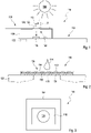
- FIG 1 a side view of an embodiment of a kit 110 for detecting at least one analyte in at least one sample 114 comprising a mobile device 112 and a test strip 116 is illustrated.
- the mobile device 112 as shown in Figure 1 , comprises at least one camera 118, at least one illumination source 120 and at least one processor 122.
- the test strip 116 comprises at least one test field 124, comprising at least one test chemical 126 for performing an optical detection reaction in the presence of the analyte.
- three examples of rays of light may be illustrated in Figure 1 by three dashed arrows.
- a first dashed arrow may indicate ambient or incident light shining from an arbitrary ambient light source 128, such as the sun, a lamp or any other light source, onto a test field 124.
- a second dashed arrow may indicate light emitted by the illumination source 120 when the illumination source 120 is turned on. Thus, the second dashed arrow may indicate light only present in case the illumination source 120 is turned on. In case the illumination source 120 is turned off, no light may be emitted from the illumination source 120 of the mobile device 112.
- a third dashed arrow may indicate light shining onto the camera 118. Specifically, in case the illumination source 120 is turned off, the light shining onto the camera 118, e.g.
- the light indicated by the third dashed arrow may comprise ambient or incident light transmitted through the test strip 116, for example through the test field 124, onto the camera 118.
- the illumination source 120 is turned on, the light shining onto the camera 118, e.g. the light indicated by the third dashed arrow, may comprise ambient or incident light transmitted through the test strip 116 as well as light emitted from the illumination source 120.
- the illumination source 120 is turned on, the light shining onto the camera 118 may for example be reflected by the test strip 116, such as for example by the test field 124, and/or by a holder 130, wherein the holder 130 may be comprised by the kit 110.
- test strip 116 having the test field 124, the test field 124 comprising the at least one test chemical 126
- the test strip 116 may comprise a substrate or carrier 132, wherein the test field 124, as an example, may be applied to the carrier 132.
- the test field 124 as illustrated in Figure 2 , may for example comprise multiple layers such as, for example, a wetting layer 134 for equally spreading the sample 114, a filter layer 136 for filtering or separating sample 114 components for a subsequent color-change detection reaction which may be performed by the test chemical 126. Other structures or layer build-up may be feasible.
- the test chemical 126 may be arranged such that the color-change may be identifiable on a first side 138 of the test field 124.
- the first side 138 may be arranged opposing a second side 140 of the test field 124, wherein the sample 114 may be applied to the second side 140 of the test field 124.
- the camera 118 may be arranged such as to face the first side 138 of the test field 124.
- Figure 3 illustrates an embodiment of an image 142 captured by the camera 118 of the mobile device 112.
- the image 142 may be of at least one region 144 of the test strip 116 comprising at least a part of the test field 124, wherein the test field 124 for example may be translucent.
- the region 144 may further fully or partially comprise a reference field 146, wherein the reference field 146, as an example, may be opaque and may contain at least one white field.
- FIGs 4A and B embodiments of graphs of an influence of ambient light on a color of the test field 124 and the reference field 146, are illustrated.
- the x-axis may indicate the time t, for example measured in seconds
- the y-axis may indicate a color or reflectivity R.
- the graph in Figure 4A illustrates an influence of ambient light on a determined color or reflectivity of the test field 124 and on a determined color of the reference field 146.
- determined colors or reflectivities R of the test field 124, illustrated in a solid line, and the reference field 146, illustrated in a dotted line, are shown for three different illumination conditions over time.
- the ambient light source 128 may be turned off and the illumination source 120 of the mobile device 112 may be turned on.
- both the illumination source 120 of the mobile device 112 and the ambient light source 128 may be turned on.
- the ambient light may have a higher level of brightness than in the second illumination condition.
- the test field 124 shows a different color, e.g. a different color coordinate value, a different color-specific intensity or a different intensity in a specific spectral color range, or reflectivity for each of the three illumination conditions.
- the determined first color 148 of the test field 124 for the first illumination condition may be less bright than the determined second color 150 of the test field 124 for the second illumination condition and the determined third color 152 of the test field 124 for the third illumination condition.
- the determined third color 152 of the test field 124 may be brighter than the determined second color 150.
- the illumination condition may have a direct impact on the determined color of the test field 124.
- a determined color 154 of the reference field 126 may be independent of the illumination condition, as can be seen in the graph illustrated in Figure 4A .
- the graph in Figure 4B illustrates an influence of a combination of ambient light and of the illumination source 120 being turned on or off and of the sample 114 being or not being applied to the test field 124, on a determined color of the test field 124 and on a determined color of the reference field 146.
- determined colors or reflectivities R of the test field 124, illustrated in the solid line, and of the reference field 146, illustrated in the dotted line, are shown for different conditions of illumination and of the sample 114 being or not being applied to the test field 124.
- the sample 114 is not applied to the test field 124 during the time 0 ⁇ t ⁇ 32 s.
- the sample 114 is being applied to the test field 124 and the color-change detection reaction may be performed by the test chemical 126.
- the sample is applied to the test field 124 and the color-change detection reaction may already be terminated.
- the sample application may take place within a time frame of one second or less.
- the sample may penetrate the test chemical 126, and the color change detection reaction, having its characteristic reaction kinetics, may take place.
- Figure 4B again three different illumination conditions may be used, wherein the illumination conditions used in Figure 4B differ from the illumination conditions used in Figure 4A .
- the illumination source 120 of the mobile device 112 is turned on and the ambient light source 128 is also turned on, wherein in this graph the ambient light source 128 may only be able to adapt the two stages "on" and "off'.
- the illumination source 120 is turned off whereas the ambient light source 128 is turned on.
- the illumination source 120 is turned on whereas the ambient light source 128 is turned off.
- the determined first color 156 such as a first color coordinate value, a first color-specific intensity or an intensity in a first specific spectral color range, of the reference field 146 may essentially be the same for the first illumination condition and the third illumination condition.
- the determined color of the test field 124 may show a significant dependency on the illumination condition as well as on the application of the sample 114. Specifically, the determined colors of the test field 124 may differ from each other for each illumination condition. Further, the determined color of the test field 124 may be different whether the sample 114 is applied to the test field 124 or not, even for the same illumination condition. In particular, a determined first color 160 of the test field 124 for the first illumination condition may be brighter before applying the sample 114 to the test field 124 than after applying the sample 114.
- a translucency of the test field 124 may be lessened due to the sample 114 being applied to the test field 124, thus a smaller amount of light may be transmitted through the test field 124 onto the camera 118, which may result in a color transition 159.
- the color transition 159 may lead to a less bright determined first color 160 of the test field 124 under the same first illumination condition after the sample 114 is applied to the test field 124 than before.
- the determined second color 162 as well as the determined third color 164 of the test field 124 both differ from each other and from the first color 160, and in addition, the second color 162 and the third color 164 also change in brightness due to the application of the sample 114 to the test field 124.
- FIGs 5A and B embodiments of a graph of a camera-specific transmission function 165 are shown.
- an exposure level or light intensity I specifically an intensity of incoming light
- a corresponding color or reflectivity R specifically a value of a color channel of a determined color, e.g. from one or more of R, G and B, may be illustrated on the y-axis.
- Figures 5A and B may show the same camera-specific transmission function 165.
- the x-axis may show a light intensity I in a linear scale of values of the light intensity in an arbitrary unit, wherein in Figure 5B a logarithmic scale may be used to illustrate the light intensity I.
- FIGs 6 and 7 flow charts of a detection method for detecting at least one analyte in at least one sample 114 is illustrated.
- the detection method comprises step a) (denoted with reference number 166) of providing at least one mobile device 112 having at least one camera 118 and at least one illumination source 120.
- the mobile device 112 as illustrated in Figure 1 may be provided.
- the detection method comprises step b) (denoted with reference number 168) of providing at least one test strip 116 having at least one test field 124, the test field 124 comprising at least one test chemical 126 for performing an optical detection reaction in the presence of the analyte.
- the test strip 116 illustrated in Figure 1 may be provided.
- the detection method comprises step c) (denoted with reference number 170) of applying the at least one sample 114 to the test field 124.
- step c) may be performed by way of dropping the sample 114 onto the test field 124, as illustrated in Figures 1 and 2 .
- the detection method comprises step d) (denoted with reference number 172) of capturing a plurality of images 142 of at least one region 144 of the test strip 116, the region 144 comprising at least a part of the test field 124 to which the sample 114 is applied.
- the method step d) further at least comprises the following substeps:
- substep d1) may for example be performed in the time frame t 2 ' of the graph illustrated in Figure 4B .
- substep d2) may, as an example, be performed in one or both of the time frames t 1 ' and t 3 '. It may also be possible to perform substep d2) at the beginning of the time frame t 4 ', e.g. during 16 ⁇ t ⁇ 32 s, for example before performing step e) of applying the sample 114 to the test field 124, e.g. during 32 ⁇ t ⁇ 38 s.
- substep d3) may specifically be performed after applying the sample 114 to the test field 124, such as, for example, at the end of the time frame t 4 ', e.g. during 38 ⁇ t ⁇ 58 s, and/or time frames t 5 ', t 6 ', t 7 ' and t 8 '.
- the detection method further comprises step e) (denoted with reference number 180) of determining a concentration of the analyte in the sample 114 by using the images 142 captured in step d).
- the detection method further comprises step f) (denoted with reference number 182) of comparing corresponding images captured in step d) with the illumination source 120 turned on and off, and determining differences in light intensities.
- the result of step f) is used for determining the concentration of the analyte in the sample 114, thus as an example step e) may comprise step f), as illustrated in Figure 7 .
- step f) comprises the following substeps:
- the camera-specific transmission function 165 which may be used in substep f2) may for example be illustrated in Figures 5A and B .
- an exemplary calculation is shown, which may be performed in the detection method.
- R d1 and R d2 may be comprised by the item of color information derived in step f1).
- differences in light intensities may be transformed into differences in items of color information for corresponding images by using the inverted function (2) of the camera-specific transmission function (1).
- step d3) may be performed.
- step d3) may for example comprise substep d3i) (denoted with reference number 190) of capturing at least one image 142 with the illumination source 120 turned off; and substep d3ii) (denoted with reference number 192) of capturing at least one image 142 with the illumination source 120 turned on.
- R d3i and R d3ii may be comprised by the item of color information derived in step f1).
- R d3 may for example comprise information on a true color of the test field 124, after the color-change detection reaction is performed by the test chemical 126.
- a change of color specifically a difference in the color due to the concentration of the analyte in the sample 114 independent of incident or ambient light, may for example be determined from a difference between R d12 and R d3 .
Description
- The present application refers to a detection method for detecting an analyte in a sample. The invention further relates to ta computer program with program means for performing the method according to the invention. Further, the invention refers to a mobile device and to a kit. Method, computer program, mobile device and kit according to the present invention may be used in medical diagnostics, in order to qualitatively and/or quantitatively detect one or more analytes in one or more bodily fluids. Other fields of application of the present invention however, are possible.
- In the field of medical diagnostics, in many cases, one or more analytes have to be detected in samples of a body fluid, such as blood, interstitial fluid, urine, saliva or other types of body fluids. Examples of analytes to be detected are glucose, triglycerides, lactate, cholesterol or other types of analytes typically present in these body fluids. According to the concentration and/or the presence of the analyte, an appropriate treatment may be chosen, if necessary.
- Generally, devices and methods known to the skilled person make use of test elements comprising one or more test chemistries, which, in presence of the analyte to be detected, are capable of performing one or more detectable detection reactions, such as optically detectable detection reactions. With regard to these test chemistries, reference may be made e.g. to J. Hoenes et al.: The Technology Behind Glucose Meters: Test Strips, Diabetes Technology & Therapeutics, . Other types of test chemistry are possible and may be used for performing the present invention.
- In analytical measurements, specifically analytical measurements based on color formation reactions, one technical challenge resides in the evaluation of the color change which is due to the detection reaction. Besides using dedicated analytical devices, such as handheld blood glucose meters, the use of generally available electronics such as smart phones and portable computers has become more and more popular over the recent years.
WO 2012/131386 A1 discloses a testing apparatus for performing an assay, the testing apparatus comprising: a receptacle containing a reagent, the reagent being reactive to an applied test sample by developing a color or pattern variation; a portable device, e.g. a mobile phone or a laptop, comprising a processor and an image capture device, wherein the processor is configured to process data captured by the image capture device and output a test result for the applied test sample. -
WO 2015/078954 A1 discloses a method, an analytical device and an analytical system for determining a concentration of at least one analyte in a bodily fluid is disclosed. The method comprising: a) applying a sample of the bodily fluid to a test carrier; b) illuminating the test carrier by at least one light source; c) receiving light remitted by the test carrier by using at least one detector; d) determining the concentration of the analyte by evaluating at least one detector signal generated by the detector. The at least one light source is modulated by using at least two modulation frequencies. The detector signal is demodulated with the at least two modulation frequencies in order to generate at least two demodulated detector signals, each demodulated detector signal corresponding to one of the modulation frequencies. The method comprises a fault detection based on a comparison of the at least two demodulated detector signals. -
US 2017/0343480 A1 describes a method for measuring blood glucose levels by a portable terminal using a strip module is provided. The strip module includes a dye pad having a color that changes in response to a sample applied to the dye pad. The strip module also includes a transparent strip having a first side and a second side. The first side is opposite the second side. The dye pad is mounted on the first side of the transparent strip, and the transparent strip reflects light provided from a light source of a portable terminal located adjacent to the second side and transmits the light to the dye pad. -
US 2015/233898 A1 describes a test strip module including a case, a test strip in the case, and a position anchor extending down past a mating surface to a face of a mobile computing device. The positioning anchor has a shape matching a feature on the face of the mobile computing device. -
US 6 267 722 B1 describes systems and methods for medical diagnosis or risk assessment for a patient. These systems and methods are designed to be employed at the point of care, such as in emergency rooms and operating rooms, or in any situation in which a rapid and accurate result is desired. The systems and methods process patient data, particularly data from point of care diagnostic tests or assays, including immunoassays, electrocardiograms, X-rays and other such tests, and provide an indication of a medical condition or risk or absence thereof. The systems include an instrument for reading or evaluating the test data and software for converting the data into diagnostic or risk assessment information. - Reliability and accuracy of the analytical measurement using mobile computing devices generally depends on a large number of technical factors. Specifically, a huge number of mobile devices having cameras are available on the market, all having different technical and optical properties which have to be considered for the analytical measurement. For example, measuring physical and biochemical parameters with mobile devices is disclosed in
EP 3 108 244 A1 andWO 2015/120819 A1 describing a test strip module including a case, a test strip in the case, and a position anchor extending down past a mating surface to a face of a mobile computing device. The position anchor has a shape matching a feature on the face of the mobile computing device. - In addition, the reliability and accuracy of the analytical measurement using mobile computing devices typically largely depends on illumination and lighting conditions during the measurement. For example, in
US 6,574,425 B1 a modulated light source emits light to illuminate a target surface which possesses a certain color and shade of color. Light that is reflected from the target surface is detected by an optical detector. The output from the optical detector is processed and fed back to the optical detector to compensate for any shift caused by ambient light, temperature or other external factors, and is differentially amplified to generate an output signal indicative of the color and shade of the target surface. The output signal from the differential amplifier is then demodulated by a synchronous detector to produce a substantially steady DC voltage that is indicative of the color or shade of color at the target surface. Where the target surface color shade is indicative of a certain measurable quantity or quality (such as an analyte concentration), the steady DC voltage is converted using a look-up table or mathematical formula into a corresponding quantity or quality measurement. In performing this conversion, compensation is made for any variations in modulated light source intensity due to temperature change. -
US 4,553,848 A discloses a method and device for detecting and evaluating the optical properties of a specimen, utilizing a light source that has alternating light and dark phases, a detector that picks up light from the light source by way of the specimen being examined, and a circuit that integrates and digitalizes the signals received from the detector, that includes an integrator, and that can be connected to the detector. The signals emitted from the detector are integrated both during at least part of the light phase and during at least part of the dark phase. The integral obtained during the dark phase is subtracted from that obtained during the light phase in order to determine the results. The integrator that is used to integrate the signals is used like an analog-to-digital converter of the double-integration type to convert the integral into a digital signal. To achieve maximum precision and simplicity in the integration and digitalization phase, each part of the light or dark phase is followed by a measurement-voltage period during which the signals coming from the detector are applied in sequence and with opposite mathematical signs to a single integrator. Integration is carried out over a whole number of measurement-voltage periods to form a total integral. -
EP 1 912 058 A1 - Document
EP3581921 A1 discloses a method for evaluating a suitability of lighting conditions for detecting an analyte in a sample using a camera of a mobile device. This document has been published on 18 of December 2019, after the filing date of the present specification. Hence, it does not form part of the prior art. Despite the advantages involved in using a mobile computing device for the purpose of performing an analytical measurement, several technical challenges remain. Specifically, reliability and accuracy of the measurements need to be enhanced and ensured. A major difficulty is the presence and impact of ambient light. Reliability and accuracy of the analytical measurement may significantly depend on lighting conditions during capturing of images of a test strip for analytical measurement when using the camera of a mobile phone. Specifically, ambient light may have a significant impact on the lighting conditions, for example, due to various illumination means being present at different specific locations and/or depending where the image is captured and at which day or night time the image is captured. Particularly, ambient light may interfere with evaluation of the color formed on a reagent field of a test strip. - It is therefore desirable to provide methods and devices which address the above mentioned technical challenges of analytical measurements using mobile devices such as consumerelectronics mobile devices, specifically multipurpose mobile devices which are not dedicated to analytical measurements such as smart phones or tablet computers. Specifically, methods and devices shall be proposed which ensure reliability and accuracy of the measurements.
- This problem is addressed by a detection method for detecting at least one analyte in at least one sample, a computer program, a mobile device and a kit with the features of the independent claims. Advantageous embodiments are listed in the dependent claims.
- As used in the following, the terms "have", "comprise" or "include" or any arbitrary grammatical variations thereof are used in a non-exclusive way. Thus, these terms may both refer to a situation in which, besides the feature introduced by these terms, no further features are present in the entity described in this context and to a situation in which one or more further features are present. As an example, the expressions "A has B", "A comprises B" and "A includes B" may both refer to a situation in which, besides B, no other element is present in A (i.e. a situation in which A solely and exclusively consists of B) and to a situation in which, besides B, one or more further elements are present in entity A, such as element C, elements C and D or even further elements.
- Further, it shall be noted that the terms "at least one", "one or more" or similar expressions indicating that a feature or element may be present once or more than once typically will be used only once when introducing the respective feature or element. In the following, in most cases, when referring to the respective feature or element, the expressions "at least one" or "one or more" will not be repeated, non-withstanding the fact that the respective feature or element may be present once or more than once.
- Further, as used in the following, the terms "preferably", "more preferably", "particularly", "more particularly", "specifically", "more specifically" or similar terms are used in conjunction with optional features, without restricting alternative possibilities. Thus, features introduced by these terms are optional features and are not intended to restrict the scope of the claims in any way. The invention may, as the skilled person will recognize, be performed by using alternative features. Similarly, features introduced by "in an embodiment of the invention" or similar expressions are intended to be optional features, without any restriction regarding alternative embodiments of the invention, without any restrictions regarding the scope of the invention and without any restriction regarding the possibility of combining the features introduced in such way with other optional or non-optional features of the invention.
- In a first aspect, a detection method for detecting at least one analyte in at least one sample is disclosed. The method comprises the following steps which, as an example, may be performed in the given order. It shall be noted, however, that a different order is also possible. Further, it is possible to perform one or more of the method steps once or repeatedly. Further, it is also possible to perform two or more of the method steps simultaneously or in a timely overlapping fashion. The method comprises steps which are not listed.
- The detection method comprises the following steps:
- a) providing at least one mobile device having at least one camera and at least one illumination source;
- b) providing at least one test strip having at least one test field, the test field comprising at least one test chemical for performing an optical detection reaction in the presence of the analyte;
- c) applying the at least one sample to the test field;
- d) capturing a plurality of images of at least one region of the test strip, the region comprising at least a part of the test field to which the sample is applied, comprising
- d1) capturing at least one image before applying the sample to the test field, with the illumination source turned off;
- d2) capturing at least one image before applying the sample to the test field, with the illumination source turned on; and
- d3) capturing at least one image after applying the sample to the test field;
- e) determining a concentration of the analyte in the sample by using the images captured in step d).
- The term "detecting an analyte in a sample" as used herein is a broad term and is to be given its ordinary and customary meaning to a person of ordinary skill in the art and is not to be limited to a special or customized meaning. The term specifically may refer, without limitation, to a quantitatively and/or qualitatively determination of at least one analyte in an arbitrary sample. For example, the sample may comprise a body fluid, such as blood, interstitial fluid, urine, saliva or other types of body fluids. The result of the analytical measurement, as an example, may be a concentration of the analyte and/or the presence or absence of the analyte to be determined. Specifically, as an example, the analytical measurement may be a blood glucose measurement, thus the result of the analytical measurement may for example be a blood glucose concentration.
- For example, in step a), a mobile device having at least one camera and at least one illumination source is provided. The term "mobile device" as used herein is a broad term and is to be given its ordinary and customary meaning to a person of ordinary skill in the art and is not to be limited to a special or customized meaning. The term specifically may refer, without limitation, to a mobile electronics device, more specifically to a mobile communication device such as a cell phone a smartphone. Additionally or alternatively, as will be outlined in further detail below, the mobile device may also refer to a tablet computer, a laptop or any other type of portable computer having at least one camera and at least one illumination source.
- The term "camera" as used herein is a broad term and is to be given its ordinary and customary meaning to a person of ordinary skill in the art and is not to be limited to a special or customized meaning. The term specifically may refer, without limitation, to a device having at least one imaging element configured for recording or capturing spatially resolved one-dimensional, two-dimensional or even three-dimensional optical information. As an example, the camera may comprise at least one camera chip, such as at least one CCD chip and/or at least one CMOS chip configured for recording images. For example, the camera may be a color camera comprising at least three color pixels. The camera may be a color CMOS camera. For example, the camera may comprise black and white pixels and color pixels. The color pixels and the black and white pixels may be combined internally in the camera. The camera may comprise at least one color camera and at least one black and white camera, such as a black and white CMOS. The camera may comprise at least one black and white CMOS chip. The camera generally may comprise a one-dimensional or two-dimensional array of image sensors, such as pixels. As an example, the camera may comprise at least 10 pixels in at least one dimension, such as at least 10 pixels in each dimension. It shall be noted, however, that other cameras are also feasible. The camera may be a camera of a mobile communications device. The invention specifically shall be applicable to cameras as usually used in mobile applications such as notebook computers, tablets or, specifically, cell phones such as smart phones. Thus, specifically, the camera may be part of a mobile device which, besides the at least one camera, comprises one or more data processing devices such as one or more data processors. Other cameras, however, are feasible. The camera, besides at least one camera chip or imaging chip, may comprise further elements, such as one or more optical elements, e.g. one or more lenses. As an example, the camera may be a fix-focus camera, having at least one lens which is fixedly adjusted with respect to the camera. Alternatively, however, the camera may also comprise one or more variable lenses which may be adjusted, automatically or manually.
- The camera specifically is a color camera. Thus, such as for each pixel, color information may be provided or generated, such as color values for three colors R, G, B. A larger number of color values is also feasible, such as four colors for each pixel. Color cameras are generally known to the skilled person. Thus, as an example, each pixel of the camera chip may have three or more different color sensors, such as color recording pixels like one pixel for red (R), one pixel for green (G) and one pixel for blue (B). For each of the pixels, such as for R, G, B, values may be recorded by the pixels, such as digital values in the range of 0 to 255, depending on the intensity of the respective color. Instead of using color triples such as R, G, B, as an example, quadruples may be used, such as C, M, Y, K or the like.
- As used herein, the term "the illumination source of the mobile device" refers to an arbitrary light source of the mobile device. The term "illumination source" refers to at least one device adapted to generate light for illuminating an object. As used herein, the term "light" generally refers to electromagnetic radiation in one or more of the visible spectral range, the ultraviolet spectral range and the infrared spectral range. The term "visible spectral range" generally refers to a spectral range of 380 nm to 780 nm. Preferably, light as used within the present invention is light in the visual spectral range. The illumination source may comprise at least one light-emitting diode integrated in the mobile device. In particular, the illumination source may be a backlighting of the mobile device, in particular of the mobile phone. The mobile device may comprise further illumination devices such as at least one illumination source illuminating the display and/or the display may be de-signed as further illumination source itself.
- The illumination source has two states, an on-state in which it generates light beam for illuminating the test strip and an off-state in which the illumination source is off. As used herein, the term "is turned on" refers to that the illumination source is activated and/or switched on to illuminate the test strip. The term "is turned off" refers to that the illumination source is within an off-state or is actively switched off. As outlined above, in step d1) at least one image is captured wherein the illumination source of the mobile device is turned off. This may allow capturing an image comprising light intensities of ambient light sources only and independent from illumination provided by the illumination source of the mobile device.
- In step d2) the illumination source is turned on, such that it may be possible to capture the second image comprising illumination intensities from both ambient light and from the illumination by the illumination source of the mobile device.
- The illumination source may comprise at least one light-emitting diode (LED) integrated in the mobile device. The illumination source may comprise at least one white light LED. The white light LED may be controlled using a short current pulse such that the white light LED may be adapted to generate a bright flash of light. The illumination source may be adapted to illuminate the test strip all the time during capturing of the image. In contrast to electron flashes, flash duration of the white light LED may take several 100 ms, this may allow that the illumination source illuminates the test strip all the time during capturing of the image in a flash-mode of the LED. Alternatively, the LED may be adapted to be permanently illuminating the test strip in a non-flash mode.
- In step b), at least one test strip having at least one test field may be provided. As used herein, the term "test strip" is a broad term and is to be given its ordinary and customary meaning to a person of ordinary skill in the art and is not to be limited to a special or customized meaning. The term specifically may refer, without limitation, to an arbitrary element or device configured for performing a color-change detection reaction. The test strip has a test field comprising at least one test chemical for performing an optical detection reaction in the presence of the analyte in order to detect the at least one analyte. The test element, as an example, may comprise at least one substrate, such as at least one carrier, with the at least one test field applied thereto or integrated therein. As an example, the at least one carrier may be strip-shaped, thereby rendering the test element a test strip. These test strips are generally widely in use and available. One test strip may carry a single test field or a plurality of test fields having identical or different test chemicals comprised therein. The test strip may have at least one sample applied thereto. In particular, the test strip may be a top-dosing test strip, such as a test strip configured for having the at least one sample applied thereto on a second side and further configured for performing the color-change detection reaction such that the color-change can be identified on a first side of the test strip, specifically the first side being arranged opposing the second side of the test strip.
- The term "test field" as used herein is a broad term and is to be given its ordinary and customary meaning to a person of ordinary skill in the art and is not to be limited to a special or customized meaning. The term specifically may refer, without limitation, to a coherent amount of the test chemical, such as to a field, e.g. a field of round, polygonal or rectangular shape, having one or more layers of material, with at least one layer of the test field having the test chemical comprised therein. Other layers may be present providing specific optical properties such as reflective properties, providing spreading properties for spreading the sample or providing separation properties such as for separating of particulate components of the sample, such as cellular components.
- The term "test chemical" as used herein is a broad term and is to be given its ordinary and customary meaning to a person of ordinary skill in the art and is not to be limited to a special or customized meaning. The term specifically may refer, without limitation, to a chemical compound or a plurality of chemical compounds such as a mixture of chemical compounds suited for performing a detection reaction in the presence of the analyte, wherein the detection reaction is detectable by specific means, such as optically. The detection reaction specifically may be analyte-specific. The test chemical, in the present case, specifically may be an optical test chemical, such as a color-change test chemical which changes in color in the presence of the analyte. The color change specifically may depend on the amount of analyte present in the sample. The test chemical, as an example, may comprise at least one enzyme, such as glucose oxidase and/or glucose dehydrogenase. Additionally, other components may be present, such as one or more dyes, mediators and the like. Test chemicals are generally known to the skilled person and reference may be made to J. Hoenes et al.: Diabetes Technology and Therapeutics, Vol. 10, . Other test chemicals, however, are feasible, too.
- The term "analyte" as used herein is a broad term and is to be given its ordinary and customary meaning to a person of ordinary skill in the art and is not to be limited to a special or customized meaning. The term specifically may refer, without limitation, to one or more specific chemical compounds and/or other parameters to be detected and/or measured. As an example, the at least one analyte may be a chemical compound which takes part in metabolism, such as one or more of glucose, cholesterol or triglycerides. Additionally or alternatively, other types of analytes or parameters may be determined, e.g. a pH value.
- As used herein, without limitation, the term "image" specifically may relate to data recorded by using a camera, such as a plurality of electronic readings from an imaging device, such as the pixels of the camera chip. The image itself, thus, may comprise pixels, the pixels of the image correlating to pixels of the camera chip. Consequently, when referring to "pixels", reference is either made to the units of image information generated by the single pixels of the camera chip or to the single pixels of the camera chip directly. The image may comprise raw pixel data. For example, the image may comprise data in the RGGB space, single color data from one of R, G or B pixels, a Bayer pattern image or the like. The image may comprise evaluated pixel data such as a full-color image or an RGB image. The raw pixel data may be evaluated for example by using demosaicing algorithms and/or filtering algorithms. These techniques are generally known to the skilled person.
- The term "capturing at least one image" refers to one or more of imaging, image recording, image acquisition, image capturing. The term "capturing at least one image" may comprise capturing a single image and/or a plurality of images such as a sequence of images. The capturing of the at least one image may be initiated by the user action or may automatically be initiated, e.g. once the presence of the at least one object within a field of view and/or within a predetermined sector of the field of view of the camera is automatically detected. These automatic image acquisition techniques are known e.g. in the field of automatic barcode readers, such as for example from automatic barcode reading apps.
- For example, in step d) a plurality of images of at least one region of the test strip is captured. The at least one region of the test strip comprises at least part of the test field to which the sample is applied. In particular, as outlined above, the images captured in step d) are used for determining the concentration of the analyte in the sample in step e).
- In addition, the detection method further comprises step f) of comparing corresponding images captured in step d) with the illumination source turned on and off, and determining a difference in light intensities. Specifically, the term "corresponding images" may refer, without limitation, to at least two images of an object, such as the test strip, wherein one of the at least two images is captured with the illumination source turned on and wherein the other one of the at least two images is captured with the illumination source turned off, preferably with the other conditions of the situation unchanged. As an example, the at least one image captured in step d1) may be compared with the at least one image captured in step d2). Additionally or alternatively, the at least one image captured in step d3) may for example be compared with one of the images captured in step d1) and/or step d2). In particular, step f) comprises determining information on the differences in light intensities between corresponding images captured in step d).
- Further, step e) comprises using the result of step f) for determining the concentration of the analyte in the sample. Specifically, the differences in light intensities determined in step f) may be used for determining the concentration of the analyte in the sample. Thus, the information on the differences in light intensities may for example be taken into account when determining the concentration of the analyte in the sample.
- Further, step f) comprises
- f1) deriving at least one item of color information of the part of the test field to which the sample is applied for each image to be compared;
- f2) transforming the item of color information into at least one item of the light intensity information by using at least one camera-specific transmission function; and
- f3) determining the differences in light intensities by using the items of light intensity information of corresponding images with the illumination source turned on and off.
- The term "item of color information" as used herein is a broad term and is to be given its ordinary and customary meaning to a person of ordinary skill in the art and is not to be limited to a special or customized meaning. The term specifically may refer, without limitation, to an indication or information regarding the color of an arbitrary object, such as for example in the present case of the color of at least the part of the test field to which the sample may be applied. As an example, the item of color information may indicate the color of the part of the test field by using coordinates for describing the color in an arbitrary color coordinate system. Thus, the at least one item of color information, specifically, may imply at least one item of photometric information, indicating a light intensity of illumination, weighted with one or more spectral sensitivity functions, such as one or more spectral sensitivity functions determined by the spectral sensitivity of the camera or a component thereof, e.g. a camera chip and/or one or more spectral filters, e.g. R, G, B filters. Several color coordinate systems are generally known to the skilled person and may also be used in the context of the present invention. In particular, the item of color information may comprise information on one, more than one or even all of the color coordinates of several or even all of the pixels of at least one image showing at least the part of the test field to which the sample may be applied. The item of color information, as an example, may be digital information. In particular, the item of color information may be or may comprise, for example, at least one digital value in the range of 0 to 255 for one or more color coordinates, such as for example for one or more of R, G and B.
- As an example, the item of color information may in particular comprise information on an intensity, specifically in case only one color coordinate is evaluated. Thus, as an example, specifically in case one color coordinate is considered and/or evaluated, the color information may be or may comprise a value of a color channel or color coordinate, wherein, as an example, a high value also may correspond to a high intensity, and a low value may correspond to a low intensity. In general, a change of color may also be accompanied by a change of intensity. Specifically, in this case, steps f1) and f2) listed above not necessarily have to be separate method steps. Thus, steps f1) and f2) at least partially may be combined.
- In a simple case, as an example, the item of color information may be or may comprise the value for a color coordinate which is known to undergo a most significant or profound change during the color-change or color formation reaction of the test chemical. As an example, in case a specific test chemical is known to change its hue most profoundly in the blue spectral range during the color-change reaction used for detecting the analyte, a blue color coordinate may be used, and the item of color information may be or may comprise the values of the blue color coordinate determined for all of the pixels or for at least a group of the pixels of at least the part of the test field within the image to which the sample may be applied.
- As indicated above, the item of color information is transformed into at least one item of the light intensity information, in substep f2), by using the at least one camera-specific transmission function. As used herein, the term "item of light intensity information" is a broad term and is to be given its ordinary and customary meaning to a person of ordinary skill in the art and is not to be limited to a special or customized meaning. The term specifically may refer, without limitation, to an indication of information regarding the light intensity, specifically the intensity of illumination or exposure level, of an arbitrary object, such as for example in the present case of at least the part of the test field to which the sample may be applied. As an example, the item of light intensity information may indicate the light intensity of the part of the test field in terms of an exposure value (EV), such as an exposure level. The at least one item of light intensity information, specifically, may imply at least one item of information indicating a radiometric power of the illumination per unit area, such as in W/m2 or similar units. In particular, the item of light intensity information may be derived by using the at least one camera-specific transmission function.
- The term "camera-specific transmission function" as used herein is a broad term and is to be given its ordinary and customary meaning to a person of ordinary skill in the art and is not to be limited to a special or customized meaning. The term specifically may refer, without limitation, to a mathematical operation for describing an arbitrary action or behavior of the camera when transferring illumination or light intensity from at least one object, specifically of at least part of the test field to which the sample may be applied, into color information, such as into at least one item of color information. The camera-specific transmission function may particularly be dependent on technical features of the camera, such as on the imaging chip or one or more sensors, the data processing device, such as the processor, the optical elements, such as the one or more lenses, or any other technical features of the camera.
- The camera-specific transmission function, for example, may be determined by empirical or semi-empirical means and, as an example, may be predetermined or may be determined by one or more calibration processes, which may also be part of the method. Thus, as an example, the camera-specific transmission function may fully or partially be determined by using one or more reference fields with known color coordinates or known color properties. For determining the camera-specific transmission function, the one or more reference fields, as an example, may be illuminated under one or more known illumination conditions, e.g. with known intensity or intensities, and color information, such as at least one item of color information, may be measured by using the camera. Thereby, a relationship between the at least one item of color information and the intensity may be determined. The camera-specific transmission function may, e.g., be determined or stored by using one or more of a curve, a graph, an analytical transformation function, a table, a matrix or any other means indicating a value of the intensity for a specific item of color information or vice versa. The camera-specific transmission function, as an example, may be stored in a data storage device, such as a volatile or non-volatile data storage device. The camera-specific transmission function, as an example, may be predetermined for a specific type of camera. Thus, as an example, a plurality of camera-specific transmission functions may be predetermined, e.g. for a plurality of specific mobile devices, and the method may imply selecting an appropriate camera-specific transmission function from the plurality of camera-specific transmission functions in accordance with the type of mobile device.
- Further, for step e), differences in light intensities may be transformed into differences in items of color information for corresponding images. In particular, the differences in light intensities may be transformed into the differences in items of color information for corresponding images by using an inverted function of the camera-specific transmission function.
- In particular, the camera-specific transformation function may be a non-linear function. The camera-specific transformation function may, as an example, allow transforming light intensity, for example measured in exposure value (EV), into color information, such as into an RGB value. Thus, the camera-specific transformation function may for example be a non-linear light intensity transmission function. Additionally or alternatively, the camera-specific transformation function may, as an example, allow transforming light intensity or exposure level, e.g. measured in exposure value (EV), into color information, such as into JPEG brightness. Thus, the camera-specific transformation function may for example be a non-linear exposure level sensitivity function. In particular, the camera-specific transformation function may for example be one or more of a non-linear light intensity transmission function and a non-linear exposure level sensitivity function.
- Further, the substep or step d3) comprises at least two further substeps. In particular, d3) comprises
- d3i) capturing at least one image with the illumination source turned off; and
- d3ii) capturing at least one image with the illumination source turned on.
- In particular, step e) may further comprise using a difference in light intensities between the images captured in d31) and d3ii). Thus, step e) of the detection method may additionally comprise using the difference in light intensities between the images captured in d3i) and d3ii) for determining the concentration of the analyte in the sample.
- Further, one or more of steps d1) to d3) may be performed repeatedly. In particular, performing one or more of steps d1), d2) and/or d3) repeatedly, may for example allow monitoring a kinetic measurement curve of the optical detection reaction. Thus, the detection method may further comprise monitoring a kinetic measurement curve of the optical detection reaction.
- In step c) of the detection method, the sample may specifically be applied to the test field from a side opposing the camera. The test strip, specifically the top-dosing test strip, may be positioned relative to the camera such that one side of the test field may face the camera, wherein another side of the test field may be averted or facing away from the camera. In particular, the sample may be applied to the side of the test field opposing or being averted from the camera.
- Specifically, a holder may be used for positioning the test strip relative to the mobile device. In particular, the test strip may be positioned with the test field at a distance from the camera, in particular from the camera of the mobile device. As an example, the mobile device may be arranged such that the camera may face in a first direction, e.g. in an upwards direction, specifically facing a first side of the test field and the sample may be applied to a second side of the test field opposing the first side. Thus, the detection method may comprise using the holder for positioning the test strip relative to the mobile device, wherein the test strip may be positioned with the test field at a distance from the camera, wherein the camera may be on the first side of the test field and wherein the sample may be applied from the second side opposing the first side.
- The holder may, specifically, be open towards the second side, such that the test field may be uncovered on the second side. In particular, the holder may not cover the test field on the second side such that the holder may not interfere or be in the way when applying the sample to the second side of the test field. In addition, the holder may comprise an opening, such that the test field may also be uncovered on the first side.
- Further, the test field may for example be at least partially translucent. In particular, in step e) of the detection method, a contribution of ambient light shining through the test field onto the camera may be determined. The term "translucent" as used herein is a broad term and is to be given its ordinary and customary meaning to a person of ordinary skill in the art and is not to be limited to a special or customized meaning. The term specifically may refer, without limitation, to a characteristic or property of an arbitrary object permitting light, specifically incident light, to pass through the object. Wherein a translucent object generally may transmit light, thus permitting more than 0% of light to pass through, the translucent object further may not transmit incident or ambient light completely, thus permitting less than 100% of light to pass through. As an example, the translucent test field may permit a restricted amount of light to pass through the test field. Specifically incident or ambient light, e.g. incoming light shining onto the test field, may be at least partially transmitted by the test field. In particular, the test field may for example transmit up to 60% of incident light. Preferably the test field may transmit up to 40 % of incident light. More preferably, the test field may transmit up to 30 % of incident light. Specifically, the test field may for example transmit from 1 % to 60 % of incident light, preferably from 1 % to 40 % of incident light, more preferably from 1 % to 30 % of incident light. The transmission, however, may depend on the spectral properties of the incident light. Further, the transmission may specifically depend on a state or condition of the test field, such as for example on a dry or wet state of the test field. Thus, the transmission may particularly be dependent on a wetting condition, a moisture condition or a dampness condition of the test field, specifically a wetting of the test field by the sample. As an example, the test field in a dry condition may specifically show a higher transmittance of incident light, than for example the same test field in a damp or wetted condition, such as the test field having the sample applied thereto. The above-mentioned transmission values, as an example, may be given for at least one wavelength within the visible spectral range.
- The test strip may for example further comprise a reference field. In particular, at least part of the reference field may for example be comprised by the region of the test strip, specifically by the region of the test strip comprising at least part of the test field. Thus, the reference field and the test field may specifically be arranged at a close distance, such as for example next to each other.
- Further, the reference field may be opaque. Specifically, the term "opaque" may, without limitation, refer to a characteristic or property of an arbitrary object not permitting light to pass through the object. In particular, the opaque reference field may be configured to not transmit incident or ambient light through the reference field. As an example, the reference field may transmit less than 3 %, preferably less than 2 %, more preferably less than 1 % of ambient light through the reference field. Specifically, the reference field may for example be 100 % opaque, thus, the reference field as an example may transmit 0 % of incident or ambient light through the reference field.
- Step d) of the detection method may further comprise substep d4) of capturing at least one image of the reference field. In addition, the image of the reference field may for example be taken into account for step e)
- The reference field, for example, may contain at least one white field. In particular, the white field, specifically the white field comprised by the reference field, may for example be used for calibrating the camera, such as for setting a white balance of the camera.
- The detection method may further comprise at least one step of checking camera-specific properties. For example, the camera-specific transformation function may be determined in the step of checking the camera-specific properties. Other camera-specific properties such as color authenticity may also be checked in said step.
- In a further aspect a computer program comprising program means for fully or partially performing the detection method is disclosed. Thus, specifically, step d), step e) and step f) of the detection method are performed by the computer program. In particular, the computer program comprises program means, such as computer executable instructions for fully or partially performing the detection method while the computer program is being executed on a computer or on a computer network, such as for example on a processor of the mobile device. Specifically, the computer may fully or partially be integrated into the mobile device, and the computer program specifically may be embodied as a software app. In particular, the computer program may be stored on a computer-readable data carrier, such as for example on a memory or data storage of the mobile device. Alternatively however, at least part of the computer may also be located outside of the mobile device.
- Further disclosed and proposed herein is a data carrier having a data structure stored thereon, which, after loading into a computer or computer network, such as into a working memory or main memory of the computer or computer network, may execute the detection method according to one or more of the embodiments disclosed herein, i.e. steps d) and e) and f), including possible substeps.
- Further disclosed and proposed herein is a computer program product with program code means stored on a machine-readable carrier, in order to perform the method according to one or more of the embodiments disclosed herein, when the program is executed on a computer or computer network, i.e. steps d) and e) and f), including possible substeps. As used herein, a computer program product refers to the program as a tradable product. The product may generally exist in an arbitrary format, such as in a paper format, or on a computer-readable data carrier. Specifically, the computer program product may be distributed over a data network.
- Finally, disclosed and proposed herein is a modulated data signal which contains instructions readable by a computer system or computer network, for performing the detection method according to one or more of the embodiments disclosed herein, specifically one or more steps of the detection method as mentioned above or as further described below, e.g. steps d) and e) and f), including possible substeps.
- Specifically, further disclosed herein are:
- a computer or computer network comprising at least one processor, wherein the processor is adapted to perform the detection method according to one of the embodiments described in this description, i.e. steps d) and e) and f), including possible substeps,
- a computer loadable data structure that is adapted to perform the detection method according to one of the embodiments described in this description while the data structure is being executed on a computer, i.e. steps d) and e) and f), including possible substeps,
- a computer program, wherein the computer program is adapted to perform the detection method according to one of the embodiments described in this description while the program is being executed on a computer, i.e. steps d) and e) and f), including possible substeps,
- a computer program comprising program means for performing the detection method according to one of the embodiments described in this description while the computer program is being executed on a computer or on a computer network, i.e. steps d) and e) and f), including possible substeps,
- a computer program comprising program means according to the preceding embodiment, wherein the program means are stored on a storage medium readable to a computer, i.e. steps d) and e) and f), including possible substeps,
- a storage medium, wherein a data structure is stored on the storage medium and wherein the data structure is adapted to perform the detection method according to one of the embodiments described in this description after having been loaded into a main and/or working storage of a computer or of a computer network, i.e. steps d) and e) and f), including possible substeps, and
- a computer program product having program code means, wherein the program code means can be stored or are stored on a storage medium, for performing the detection method according to one of the embodiments described in this description, if the program code means are executed on a computer or on a computer network, i.e. steps d) and e) and f), including possible substeps.
- In a further aspect of the present invention, a mobile device is disclosed. The mobile device comprises
- I) at least one camera;
- II) at least one illumination source; and
- III) at least one processor.
- The mobile device is configured for performing the detection method as described herein, e.g. according to any one of the embodiments described above and/or described in further detail below, in conjunction with a test strip having at least one test field, wherein the test field comprises at least one test chemical for performing an optical detection reaction in the presence of the analyte.
- For most of the terms used herein and for possible definitions, reference may be made to the description of the detection method given above or as further described below.
- As an example, the processor may comprise program means for performing the detection method as disclosed above or as further disclosed below. Specifically, the program means is configured for performing steps d), e) and f) of the detection method.
- In a further aspect a kit for detecting at least one analyte in at least one sample is disclosed.
- The kit comprises the mobile device according to the present invention and at least one test strip having at least one test field, the test field comprising at least one test chemical for performing an optical detection reaction in the presence of the analyte.
- For most of the terms used herein and for possible definitions, reference may be made to the description of the detection method and/or the description of the mobile device given above or as further described below.
- Further, the kit may comprise at least one holder for positioning the test strip relative to the mobile device, wherein the test strip may be positioned by the holder with the test field at a distance from the camera, wherein the camera may be on a first side of the test field and wherein the sample may be applicable from a second side opposing the first side.
- Additionally, the holder may be open towards the second side, such that the test field may be uncovered on the second side. Specifically, the holder may be configured for leaving the second side of the test field uncovered, in order for the sample to be applicable to the second side of the test field, without interference of the holder.
- In particular, the holder with the test strip and the mobile device may constitute an inner space. The space, for example, may be enclosed by the mobile device, the holder and the test strip. Specifically, the holder, the test strip and the mobile device may be arranged such that the inner space may be constituted. Further, the camera and the illumination source may face the inner space. In particular, the holder may position the test strip such that the illumination source may be capable of illuminating the test field.
- The method and devices according to the present invention may provide a large number of advantages over known methods and devices for analytical measurements. The present invention may improve reliability and user-friendliness of the process of detecting an analyte in a sample, compared to processes known from the art. Specifically, the present invention may improve the reliability and user-friendliness of an application, e.g. an app, including computer-executable instructions for detecting an analyte in a sample, compared to known apps or computer programs. In particular, the present invention may allow ensuring a robust detection of the analyte in varying or non-stable imaging conditions. Specifically, the invention may provide an improved reliability and accuracy of the apps or computer programs using the mobile device's camera images because an impact of ambient light is taken into account when determining the result, specifically when detecting the analyte in the sample.
- Further optional features and embodiments will be disclosed in more detail in the subsequent description of embodiments, preferably in conjunction with the dependent embodiments. Therein, the respective optional features may be realized in an isolated fashion as well as in any arbitrary feasible combination, as the skilled person will realize. The scope of the invention is not restricted by the preferred embodiments. The embodiments are schematically depicted in the Figures. Therein, identical reference numbers in these Figures refer to identical or functionally comparable elements.
- In the Figures:
- Figure 1
- show a side view of an embodiment of a kit comprising a mobile device for performing a detection method according to the present invention;
- Figure 2
- shows an enlarged sectional view of the embodiment of the kit illustrated in
Figure 1 ; - Figure 3
- shows an embodiment of an image captured by the camera of the mobile device;
- Figures 4A and B
- show embodiments of graphs of an influence of ambient light on a color of a test field and a reference field;
- Figures 5A and B
- show embodiments of a graph of a camera-specific transmission function; and
- Figures 6 and 7
- show embodiments of flow charts of an embodiment of a detection method.
- In
Figure 1 a side view of an embodiment of akit 110 for detecting at least one analyte in at least onesample 114 comprising amobile device 112 and atest strip 116 is illustrated. Themobile device 112, as shown inFigure 1 , comprises at least onecamera 118, at least oneillumination source 120 and at least oneprocessor 122. Thetest strip 116 comprises at least onetest field 124, comprising at least onetest chemical 126 for performing an optical detection reaction in the presence of the analyte. Further, three examples of rays of light may be illustrated inFigure 1 by three dashed arrows. A first dashed arrow may indicate ambient or incident light shining from an arbitrary ambientlight source 128, such as the sun, a lamp or any other light source, onto atest field 124. A second dashed arrow may indicate light emitted by theillumination source 120 when theillumination source 120 is turned on. Thus, the second dashed arrow may indicate light only present in case theillumination source 120 is turned on. In case theillumination source 120 is turned off, no light may be emitted from theillumination source 120 of themobile device 112. A third dashed arrow may indicate light shining onto thecamera 118. Specifically, in case theillumination source 120 is turned off, the light shining onto thecamera 118, e.g. the light indicated by the third dashed arrow, may comprise ambient or incident light transmitted through thetest strip 116, for example through thetest field 124, onto thecamera 118. Alternatively, in case theillumination source 120 is turned on, the light shining onto thecamera 118, e.g. the light indicated by the third dashed arrow, may comprise ambient or incident light transmitted through thetest strip 116 as well as light emitted from theillumination source 120. In particular, in case theillumination source 120 is turned on, the light shining onto thecamera 118 may for example be reflected by thetest strip 116, such as for example by thetest field 124, and/or by aholder 130, wherein theholder 130 may be comprised by thekit 110. - In
Figure 2 an enlarged sectional view of the embodiment of thekit 110 as illustrated inFigure 1 is shown. In particular, thetest strip 116 having thetest field 124, thetest field 124 comprising the at least onetest chemical 126, is shown. As an example, thetest strip 116 may comprise a substrate orcarrier 132, wherein thetest field 124, as an example, may be applied to thecarrier 132. Thetest field 124, as illustrated inFigure 2 , may for example comprise multiple layers such as, for example, awetting layer 134 for equally spreading thesample 114, afilter layer 136 for filtering or separatingsample 114 components for a subsequent color-change detection reaction which may be performed by thetest chemical 126. Other structures or layer build-up may be feasible. As an example, thetest chemical 126 may be arranged such that the color-change may be identifiable on afirst side 138 of thetest field 124. In particular, thefirst side 138 may be arranged opposing asecond side 140 of thetest field 124, wherein thesample 114 may be applied to thesecond side 140 of thetest field 124. Specifically, thecamera 118 may be arranged such as to face thefirst side 138 of thetest field 124. -
Figure 3 illustrates an embodiment of animage 142 captured by thecamera 118 of themobile device 112. Theimage 142, as an example, may be of at least oneregion 144 of thetest strip 116 comprising at least a part of thetest field 124, wherein thetest field 124 for example may be translucent. As an example, theregion 144 may further fully or partially comprise areference field 146, wherein thereference field 146, as an example, may be opaque and may contain at least one white field. - In
Figures 4A and B , embodiments of graphs of an influence of ambient light on a color of thetest field 124 and thereference field 146, are illustrated. In the graphs, the x-axis may indicate the time t, for example measured in seconds, and the y-axis may indicate a color or reflectivity R. The graph inFigure 4A illustrates an influence of ambient light on a determined color or reflectivity of thetest field 124 and on a determined color of thereference field 146. In particular, determined colors or reflectivities R of thetest field 124, illustrated in a solid line, and thereference field 146, illustrated in a dotted line, are shown for three different illumination conditions over time. As an example, in a first illumination condition the ambientlight source 128 may be turned off and theillumination source 120 of themobile device 112 may be turned on. Specifically, in the graph, the first illumination condition may be used in the time frames t1, t3, t5 and t7 wherein t1 = 0 ≤ t < 2 s, t3 = 11 ≤ t < 18 s, ts = 32 ≤ t < 34 and t7 = 39 ≤ t < 41 s. In a second and third illumination condition both theillumination source 120 of themobile device 112 and the ambientlight source 128 may be turned on. However, in the third illumination condition the ambient light may have a higher level of brightness than in the second illumination condition. Specifically, in the graph, the second illumination condition may be used in the time frame t2, wherein t2 = 2 ≤ t < 11 s and the third illumination condition may be used in the time frames t4 and t6, wherein t4 = 18 ≤ t < 32 and t6 = 34 ≤ t < 39 s. In the graph, as illustrated inFigure 4A , thetest field 124 shows a different color, e.g. a different color coordinate value, a different color-specific intensity or a different intensity in a specific spectral color range, or reflectivity for each of the three illumination conditions. In particular, the determinedfirst color 148 of thetest field 124 for the first illumination condition may be less bright than the determinedsecond color 150 of thetest field 124 for the second illumination condition and the determinedthird color 152 of thetest field 124 for the third illumination condition. Additionally, the determinedthird color 152 of thetest field 124 may be brighter than the determinedsecond color 150. Thus, the illumination condition may have a direct impact on the determined color of thetest field 124. However, adetermined color 154 of thereference field 126 may be independent of the illumination condition, as can be seen in the graph illustrated inFigure 4A . - It may be noted that given time specifications, such as for example the specific times of the time frames, as stated in the description of the figures are given for exemplary purpose and thus serve to illustrate possible embodiments and are not to be construed as limiting the scope thereof.
- The graph in
Figure 4B illustrates an influence of a combination of ambient light and of theillumination source 120 being turned on or off and of thesample 114 being or not being applied to thetest field 124, on a determined color of thetest field 124 and on a determined color of thereference field 146. In particular, determined colors or reflectivities R of thetest field 124, illustrated in the solid line, and of thereference field 146, illustrated in the dotted line, are shown for different conditions of illumination and of thesample 114 being or not being applied to thetest field 124. Specifically, in the graph, thesample 114 is not applied to thetest field 124 during thetime 0 ≤ t < 32 s. Subsequently, during the time 32 ≤ t < 38 s thesample 114 is being applied to thetest field 124 and the color-change detection reaction may be performed by thetest chemical 126. During the subsequent time 38 ≤ t < 86 s the sample is applied to thetest field 124 and the color-change detection reaction may already be terminated. As an example, the sample application may take place within a time frame of one second or less. The sample may penetrate thetest chemical 126, and the color change detection reaction, having its characteristic reaction kinetics, may take place. InFigure 4B , again three different illumination conditions may be used, wherein the illumination conditions used inFigure 4B differ from the illumination conditions used inFigure 4A . - In particular, in the first illumination condition used in
Figure 4B theillumination source 120 of themobile device 112 is turned on and the ambientlight source 128 is also turned on, wherein in this graph the ambientlight source 128 may only be able to adapt the two stages "on" and "off'. The first illumination condition used inFigure 4B may be used in the time frames ti', t4' and t7', wherein t1' = 0 ≤ t < 5 s, t4' = 16 ≤ t < 58 s and t7' = 75 ≤ t < 82 s. In the second illumination condition theillumination source 120 is turned off whereas the ambientlight source 128 is turned on. The second illumination condition may specifically be used in the time frames t2', t5' and t8', wherein t2' = 5 ≤ t < 13 s, t8' = 58 ≤ t < 68 s and t7' = 75 ≤ t < 82 s. In the third illumination condition theillumination source 120 is turned on whereas the ambientlight source 128 is turned off. The third illumination condition may specifically be used in the time frames t3' and t6', wherein t3' = 13 ≤ t < 16 s and t6' = 68 ≤ t < 75 s. - As can be seen in
Figure 4B , the determinedfirst color 156, such as a first color coordinate value, a first color-specific intensity or an intensity in a first specific spectral color range, of thereference field 146 may essentially be the same for the first illumination condition and the third illumination condition. Thus, for example, only theillumination source 120, e.g. being switched on or off, may have an impact on the determined color of thereference field 146. Specifically, as illustrated inFigure 4B , the determinedsecond color 158 of thereference field 146, e.g. determined in the time frames during which theillumination source 120 is turned off, may for example show a color or reflectivity of R = 0. However, the determined color of thetest field 124, as illustrated in the graph, may show a significant dependency on the illumination condition as well as on the application of thesample 114. Specifically, the determined colors of thetest field 124 may differ from each other for each illumination condition. Further, the determined color of thetest field 124 may be different whether thesample 114 is applied to thetest field 124 or not, even for the same illumination condition. In particular, a determinedfirst color 160 of thetest field 124 for the first illumination condition may be brighter before applying thesample 114 to thetest field 124 than after applying thesample 114. As an example, a translucency of thetest field 124 may be lessened due to thesample 114 being applied to thetest field 124, thus a smaller amount of light may be transmitted through thetest field 124 onto thecamera 118, which may result in acolor transition 159. Specifically, thecolor transition 159 may lead to a less bright determinedfirst color 160 of thetest field 124 under the same first illumination condition after thesample 114 is applied to thetest field 124 than before. Further, as illustrated in theFigure 4B , the determinedsecond color 162 as well as the determinedthird color 164 of thetest field 124 both differ from each other and from thefirst color 160, and in addition, thesecond color 162 and thethird color 164 also change in brightness due to the application of thesample 114 to thetest field 124. - In
Figures 5A and B , embodiments of a graph of a camera-specific transmission function 165 are shown. Specifically, in the graphs, an exposure level or light intensity I, specifically an intensity of incoming light, may be illustrated on the x-axis and a corresponding color or reflectivity R, specifically a value of a color channel of a determined color, e.g. from one or more of R, G and B, may be illustrated on the y-axis. As an example,Figures 5A and B may show the same camera-specific transmission function 165. However, inFigure 5A the x-axis may show a light intensity I in a linear scale of values of the light intensity in an arbitrary unit, wherein inFigure 5B a logarithmic scale may be used to illustrate the light intensity I. In particular, as an example, the camera-specific transmission function 165 illustrated in the graphs may be mathematically described as
- As an example, an inverse function of the non-linear function (2) may be mathematically described as

- In
Figures 6 and7 flow charts of a detection method for detecting at least one analyte in at least onesample 114 is illustrated. The detection method comprises step a) (denoted with reference number 166) of providing at least onemobile device 112 having at least onecamera 118 and at least oneillumination source 120. As an example, themobile device 112 as illustrated inFigure 1 may be provided. Further, the detection method comprises step b) (denoted with reference number 168) of providing at least onetest strip 116 having at least onetest field 124, thetest field 124 comprising at least onetest chemical 126 for performing an optical detection reaction in the presence of the analyte. In particular, as an example, thetest strip 116 illustrated inFigure 1 may be provided. Furthermore, the detection method comprises step c) (denoted with reference number 170) of applying the at least onesample 114 to thetest field 124. As an example, step c) may be performed by way of dropping thesample 114 onto thetest field 124, as illustrated inFigures 1 and 2 . - Further, the detection method comprises step d) (denoted with reference number 172) of capturing a plurality of
images 142 of at least oneregion 144 of thetest strip 116, theregion 144 comprising at least a part of thetest field 124 to which thesample 114 is applied. The method step d) further at least comprises the following substeps: - d1) (denoted with reference number 174) capturing at least one
image 142 before applying thesample 114 to thetest field 124, with theillumination source 120 turned off; - d2) (denoted with reference number 176) capturing at least one
image 142 before applying thesample 114 to thetest field 124, with theillumination source 120 turned on; and - d3) (denoted with reference number 178) capturing at least one
image 142 after applying thesample 114 to thetest field 124. - In particular, substep d1) may for example be performed in the time frame t2' of the graph illustrated in
Figure 4B . Further, substep d2) may, as an example, be performed in one or both of the time frames t1' and t3'. It may also be possible to perform substep d2) at the beginning of the time frame t4', e.g. during 16 ≤ t < 32 s, for example before performing step e) of applying thesample 114 to thetest field 124, e.g. during 32 ≤ t < 38 s. Further, substep d3) may specifically be performed after applying thesample 114 to thetest field 124, such as, for example, at the end of the time frame t4', e.g. during 38 ≤ t < 58 s, and/or time frames t5', t6', t7' and t8'. - The detection method further comprises step e) (denoted with reference number 180) of determining a concentration of the analyte in the
sample 114 by using theimages 142 captured in step d). As illustrated inFigure 7 , the detection method further comprises step f) (denoted with reference number 182) of comparing corresponding images captured in step d) with theillumination source 120 turned on and off, and determining differences in light intensities. The result of step f) is used for determining the concentration of the analyte in thesample 114, thus as an example step e) may comprise step f), as illustrated inFigure 7 . - As further illustrated in
Figure 7 , step f) comprises the following substeps: - f1) (denoted with reference number 184) deriving at least one item of color information of the part of the test field to which the sample is applied for each image to be compared;
- f2) (denoted with reference number 186) transforming the item of color information into at least one item of the light intensity information by using at least one camera-
specific transmission function 165; - f3) (denoted with reference number 188) determining the differences in light intensities by using the items of light intensity information of corresponding images with the illumination source turned on and off.
- As an example, the camera-
specific transmission function 165, which may be used in substep f2) may for example be illustrated inFigures 5A and B . Thus, in the following, an exemplary calculation is shown, which may be performed in the detection method. Theimage 142 captured in step d1) may for example show a color or reflectivity of Rd1 = 230 and theimage 142 captured in step d2) may for example show a color or reflectivity of Rd2 = 80. As an example, Rd1 and Rd2 may be comprised by the item of color information derived in step f1). As an example, in step f2), the inverse camera-specific transmission function (2) may be used for transforming Rd1 and Rd2 into light intensities Id1 = 80 and Id2 = 15. Subsequently, a difference in the light intensities may be determined in step f3), such as for example Id12 = 80 - 15 = 65. In particular, for step e), differences in light intensities, as an example, may be transformed into differences in items of color information for corresponding images by using the inverted function (2) of the camera-specific transmission function (1). Thus, as an example Rd12(Id12 = 65) = 211 may be calculated. In particular, the differences in items of color information, e.g. Rd12, may for example comprise information on a true color of the test field, such as for example the color of the reference field without interference of external or ambient light, before thesample 114 may be applied to thetest field 124. - After applying the
sample 114 to the test field, e.g. after performing step c), step d3) may be performed. In particular, step d3) may for example comprise substep d3i) (denoted with reference number 190) of capturing at least oneimage 142 with theillumination source 120 turned off; and substep d3ii) (denoted with reference number 192) of capturing at least oneimage 142 with theillumination source 120 turned on. As an example, theimages 142 captured in step d3) may show a color or reflectivity of Rd3i = 190 and Rd3ii = 15. As an example, Rd3i and Rd3ii may be comprised by the item of color information derived in step f1). Again, as an example, using the inverted function (2) of the camera-specific transmission function (1), corresponding light intensities Id3i = 51 and Id3ii = 7, may be determined, e.g. in step f2), leading to a difference in light intensities Id3 = 44. Subsequently, as an example, Rd3(Id3 = 44) = 176, may be calculated. Rd3 may for example comprise information on a true color of thetest field 124, after the color-change detection reaction is performed by thetest chemical 126. Thus, a change of color, specifically a difference in the color due to the concentration of the analyte in thesample 114 independent of incident or ambient light, may for example be determined from a difference between Rd12 and Rd3. -
- 110
- kit
- 112
- sample
- 114
- mobile device
- 116
- test strip
- 118
- camera
- 120
- illumination source
- 122
- processor
- 124
- test field
- 126
- test chemical
- 128
- ambient light source
- 130
- holder
- 132
- carrier
- 134
- wetting layer
- 136
- filter layer
- 138
- first side
- 140
- second side
- 142
- image
- 144
- region
- 146
- reference field
- 148
- first color of test field
- 150
- second color of test field
- 152
- third color of test field
- 154
- color of reference field
- 156
- first color of reference field
- 158
- second color of reference field
- 159
- color transition
- 160
- first color of test field
- 162
- second color of test field
- 164
- third color of test field
- 165
- camera-specific transmission function
- 166
- step a)
- 168
- step b)
- 170
- step c)
- 172
- step d)
- 174
- step dl)
- 176
- step d2)
- 178
- step d3)
- 180
- step e)
- 182
- step f)
- 184
- step f1)
- 186
- step f2)
- 188
- step f3)
- 190
- step d3i)
- 192
- step d3ii)
Claims (11)
- A detection method for detecting at least one analyte in at least one sample (114), the method comprising:a) providing at least one mobile device (112) having at least one camera (118) and at least one illumination source (120);b) providing at least one test strip (116) having at least one test field (124), the test field comprising at least one test chemical (126) for performing an optical detection reaction in the presence of the analyte;c) applying the at least one sample (114) to the test field (124);d) capturing a plurality of images (142) of at least one region (144) of the test strip (116), the region (144) comprising at least a part of the test field (124) to which the sample (114) is applied, comprisingd1) capturing at least one image (142) before applying the sample (114) to the test field (124), with the illumination source (120) turned off;d2) capturing at least one image (142) before applying the sample (114) to the test field (124), with the illumination source (120) turned on; andd3) capturing at least one image (142) after applying the sample (114) to the test field (124), wherein step d3) comprisesd3i) capturing at least one image (142) with the illumination source (120) turned off; andd3ii) capturing at least one image (142) with the illumination source (120) turned one) determining a concentration of the analyte in the sample (114) by using the images (142) captured in step d);characterized in that, the method further comprises:f) comparing corresponding images captured in step d) with the illumination source turned (120) on and off, and determining differences in light intensities, wherein step f) comprisesf1) deriving at least one item of color information of the part of the test field (124) to which the sample (114) is applied for each image (142) to be compared;f2) transforming the item of color information into at least one item of the light intensity information by using at least one camera-specific transmission function (165);f3) determining the differences in light intensities by using the items of light intensity information of corresponding images with the illumination source (120) turned on and off.wherein step e) comprises using the result of step f) for determining the concentration of the analyte in the sample (114).
- The method according to the preceding claim, wherein, for step e), differences in light intensities are transformed into differences in items of color information for corresponding images by using an inverted function of the camera-specific transmission function (165), wherein the camera-specific transmission function (165) is a non-linear function transforming the item of color information into the item of light intensity information.
- The method according to any one of the preceding claims, wherein step e) further comprises using a difference in light intensities between images (142) captured in d3i) and d3ii).
- The method according to any one of the preceding claims, wherein, in step c), the sample (114) is applied to the test field (124) from a side opposing the camera (118).
- The method according to the preceding claim, wherein a holder (130) is used for positioning the test strip (116) relative to the mobile device (112), wherein the test strip (116) is positioned with the test field (124) at a distance from the camera (118), wherein the camera (118) is on a first side (138) of the test field (124) and wherein the sample (114) is applied from a second side (140) opposing the first side (138).
- The method according to the preceding claim, wherein the holder (130) is open towards the second side (140), such that the test field (124) is uncovered on the second side (140), wherein the holder (130) comprises an opening, such that the test field (124) is uncovered on the first side (138).
- The method according to any one of the preceding claims, wherein the test field (124) is at least partially translucent, wherein, in step e), a contribution of ambient light shining through the test field (124) onto the camera (118) is determined.
- The method according to any one of the preceding claims, wherein the test strip (116) further comprises a reference field (146), wherein the region (144) of the test strip (124) further comprises at least a part of the reference field (146), wherein the reference field (146) is opaque, wherein method step d) further comprises: step d4) capturing at least one image (142) of the reference field (146), and wherein the image (142) of the reference field (146) is taken into account for step e).
- A computer program comprising program means for performing at least step d), step e) and step f) of the method according to any one of the preceding claims, while the computer program is being executed on a computer or on a computer network.
- A mobile device (112), comprising:I) at least one camera (118);II) at least one illumination source (120); andIII) at least one processor (122),wherein the mobile device (112) is configured for performing the detection method for detecting the at least one analyte in the at least one sample (114) according to any one of claims 1 to 8 in conjunction with a test strip (116) having at least one test field (124), the test field (124) comprising at least one test chemical (126) for performing an optical detection reaction in the presence of the analyte.
- A kit (110) for detecting at least one analyte in at least one sample (114), the kit (110) comprising the mobile device (112) according to the preceding claim, the kit (110) further comprising at least one test strip (116) having at least one test field (124), the test field (124) comprising at least one test chemical (126) for performing an optical detection reaction in the presence of the analyte.
Applications Claiming Priority (2)
| Application Number | Priority Date | Filing Date | Title |
|---|---|---|---|
| EP18182167.9A EP3591385A1 (en) | 2018-07-06 | 2018-07-06 | A detection method for detecting an analyte in a sample |
| PCT/EP2019/067815 WO2020007896A1 (en) | 2018-07-06 | 2019-07-03 | A detection method for detecting an analyte in a sample |
Publications (2)
| Publication Number | Publication Date |
|---|---|
| EP3811061A1 EP3811061A1 (en) | 2021-04-28 |
| EP3811061B1 true EP3811061B1 (en) | 2022-05-11 |
Family
ID=62874755
Family Applications (2)
| Application Number | Title | Priority Date | Filing Date |
|---|---|---|---|
| EP18182167.9A Withdrawn EP3591385A1 (en) | 2018-07-06 | 2018-07-06 | A detection method for detecting an analyte in a sample |
| EP19735317.0A Active EP3811061B1 (en) | 2018-07-06 | 2019-07-03 | A detection method for detecting an analyte in a sample |
Family Applications Before (1)
| Application Number | Title | Priority Date | Filing Date |
|---|---|---|---|
| EP18182167.9A Withdrawn EP3591385A1 (en) | 2018-07-06 | 2018-07-06 | A detection method for detecting an analyte in a sample |
Country Status (11)
| Country | Link |
|---|---|
| US (1) | US20210131973A1 (en) |
| EP (2) | EP3591385A1 (en) |
| JP (1) | JP7356490B2 (en) |
| KR (1) | KR20210028180A (en) |
| CN (1) | CN112334759A (en) |
| BR (1) | BR112021000111A2 (en) |
| CA (1) | CA3104213A1 (en) |
| ES (1) | ES2922311T3 (en) |
| MA (1) | MA52952B1 (en) |
| PL (1) | PL3811061T3 (en) |
| WO (1) | WO2020007896A1 (en) |
Families Citing this family (7)
| Publication number | Priority date | Publication date | Assignee | Title |
|---|---|---|---|---|
| US8422740B2 (en) * | 2009-01-15 | 2013-04-16 | Scott Dylewski | Methods for determining a liquid front position on a test strip |
| DE102019205009A1 (en) * | 2019-04-08 | 2020-10-08 | Zf Friedrichshafen Ag | Method, control device, set and computer program product for calibrating a camera and calibrating a vehicle camera with night vision capability |
| USD970033S1 (en) | 2020-10-23 | 2022-11-15 | Becton, Dickinson And Company | Cartridge imaging background device |
| CN113552118A (en) * | 2021-07-15 | 2021-10-26 | 海口市骨科与糖尿病医院(上海市第六人民医院海口骨科与糖尿病医院) | Detection method for indicating card in surgical instrument package |
| CN114414500B (en) * | 2022-03-28 | 2022-08-02 | 深圳市脉度科技有限公司 | Spectrum detection method, storage medium, electronic device, and apparatus |
| EP4279905A1 (en) | 2022-05-20 | 2023-11-22 | F. Hoffmann-La Roche AG | Method of individualizing analyte value ranges used to categorize a concentration of an analyte |
| EP4278967A1 (en) | 2022-05-20 | 2023-11-22 | F. Hoffmann-La Roche AG | Method of determining a final numerical analyte result value corresponding to a concentration of an analyte in a bodily fluid using a mobile device |
Citations (1)
| Publication number | Priority date | Publication date | Assignee | Title |
|---|---|---|---|---|
| EP3581921A1 (en) * | 2018-06-11 | 2019-12-18 | Roche Diabetes Care GmbH | Method for evaluating a suitability of lighting conditions for detecting an analyte in a sample using a camera of a mobile device |
Family Cites Families (16)
| Publication number | Priority date | Publication date | Assignee | Title |
|---|---|---|---|---|
| DE3138879A1 (en) | 1981-09-30 | 1983-04-14 | Boehringer Mannheim Gmbh, 6800 Mannheim | METHOD FOR DETECTING PHOTOMETRIC SIGNALS AND ARRANGEMENT FOR IMPLEMENTING THE METHOD |
| BR9815205B1 (en) | 1997-10-31 | 2012-10-30 | reflectometer and read head for a reflectometer. | |
| US6267722B1 (en) * | 1998-02-03 | 2001-07-31 | Adeza Biomedical Corporation | Point of care diagnostic systems |
| DE10163775A1 (en) | 2001-12-22 | 2003-07-03 | Roche Diagnostics Gmbh | Analysis system for determining an analyte concentration taking into account sample and analyte-independent changes in light intensity |
| US20050227370A1 (en) | 2004-03-08 | 2005-10-13 | Ramel Urs A | Body fluid analyte meter & cartridge system for performing combined general chemical and specific binding assays |
| DE502006008518D1 (en) | 2006-10-14 | 2011-01-27 | Roche Diagnostics Gmbh | Arrangement and method for detecting and evaluating optical signals |
| JP2008232662A (en) | 2007-03-16 | 2008-10-02 | Matsushita Electric Ind Co Ltd | Optical measuring device |
| GB0904080D0 (en) | 2009-03-09 | 2009-04-22 | Mologic Ltd | Imaging method |
| GB201105474D0 (en) | 2011-03-31 | 2011-05-18 | Albagaia Ltd | Testing apparatus |
| JP6139565B2 (en) | 2012-02-06 | 2017-05-31 | ザ リージェンツ オブ ザ ユニバーシティ オブ カリフォルニアThe Regents Of The University Of California | Portable rapid diagnostic test reader |
| US9241663B2 (en) | 2012-09-05 | 2016-01-26 | Jana Care Inc. | Portable medical diagnostic systems and methods using a mobile device |
| JP6010434B2 (en) | 2012-11-15 | 2016-10-19 | 株式会社オーイーエムシステム | Body fluid component analyzer and body fluid component analysis method |
| US9778200B2 (en) | 2012-12-18 | 2017-10-03 | Ixensor Co., Ltd. | Method and apparatus for analyte measurement |
| CA2926287C (en) | 2013-11-28 | 2020-03-24 | F. Hoffmann-La Roche Ag | Method and device for determining a concentration of an analyte in a bodily fluid |
| US9658217B2 (en) * | 2014-02-17 | 2017-05-23 | Ixensor Co., Ltd | Measuring physical and biochemical parameters with mobile devices |
| US11092590B2 (en) | 2016-05-25 | 2021-08-17 | Samsung Electronics Co., Ltd | Strip module and method for acquiring information of a sample |
-
2018
- 2018-07-06 EP EP18182167.9A patent/EP3591385A1/en not_active Withdrawn
-
2019
- 2019-07-03 ES ES19735317T patent/ES2922311T3/en active Active
- 2019-07-03 MA MA52952A patent/MA52952B1/en unknown
- 2019-07-03 KR KR1020217000154A patent/KR20210028180A/en not_active Application Discontinuation
- 2019-07-03 PL PL19735317.0T patent/PL3811061T3/en unknown
- 2019-07-03 CN CN201980045256.5A patent/CN112334759A/en active Pending
- 2019-07-03 JP JP2021500064A patent/JP7356490B2/en active Active
- 2019-07-03 BR BR112021000111-5A patent/BR112021000111A2/en active Search and Examination
- 2019-07-03 EP EP19735317.0A patent/EP3811061B1/en active Active
- 2019-07-03 CA CA3104213A patent/CA3104213A1/en active Pending
- 2019-07-03 WO PCT/EP2019/067815 patent/WO2020007896A1/en active Application Filing
-
2021
- 2021-01-05 US US17/142,129 patent/US20210131973A1/en active Pending
Patent Citations (1)
| Publication number | Priority date | Publication date | Assignee | Title |
|---|---|---|---|---|
| EP3581921A1 (en) * | 2018-06-11 | 2019-12-18 | Roche Diabetes Care GmbH | Method for evaluating a suitability of lighting conditions for detecting an analyte in a sample using a camera of a mobile device |
Also Published As
| Publication number | Publication date |
|---|---|
| EP3811061A1 (en) | 2021-04-28 |
| PL3811061T3 (en) | 2022-08-22 |
| BR112021000111A2 (en) | 2021-04-06 |
| MA52952B1 (en) | 2022-07-29 |
| CN112334759A (en) | 2021-02-05 |
| CA3104213A1 (en) | 2020-01-09 |
| TW202016543A (en) | 2020-05-01 |
| ES2922311T3 (en) | 2022-09-13 |
| US20210131973A1 (en) | 2021-05-06 |
| MA52952A (en) | 2021-04-28 |
| EP3591385A1 (en) | 2020-01-08 |
| JP7356490B2 (en) | 2023-10-04 |
| JP2021530681A (en) | 2021-11-11 |
| WO2020007896A1 (en) | 2020-01-09 |
| KR20210028180A (en) | 2021-03-11 |
Similar Documents
| Publication | Publication Date | Title |
|---|---|---|
| EP3811061B1 (en) | A detection method for detecting an analyte in a sample | |
| US9506855B2 (en) | Method and system for analyzing a colorimetric assay | |
| EP3650843B1 (en) | Methods and devices for performing an analytical measurement | |
| US11835515B2 (en) | Method for evaluating suitability of lighting conditions for detecting an analyte in a sample using a camera of a mobile device | |
| Preechaburana et al. | HDR imaging evaluation of a NT-proBNP test with a mobile phone | |
| WO2017019762A1 (en) | Image based photometry | |
| RU2791099C2 (en) | Method for determining analyte in a sample | |
| TWI832873B (en) | A detection method for detecting an analyte in a sample | |
| RU2792659C2 (en) | Methods and devices for carrying out analytical measurements | |
| RU2791101C2 (en) | Method for assessment of lighting condition suitability for analyte determination in sample, using mobile device camera | |
| EP3978909A1 (en) | Method of determining the concentration of at least one analyte in a bodily fluid |
Legal Events
| Date | Code | Title | Description |
|---|---|---|---|
| STAA | Information on the status of an ep patent application or granted ep patent |
Free format text: STATUS: UNKNOWN |
|
| STAA | Information on the status of an ep patent application or granted ep patent |
Free format text: STATUS: THE INTERNATIONAL PUBLICATION HAS BEEN MADE |
|
| STAA | Information on the status of an ep patent application or granted ep patent |
Free format text: STATUS: THE INTERNATIONAL PUBLICATION HAS BEEN MADE |
|
| PUAI | Public reference made under article 153(3) epc to a published international application that has entered the european phase |
Free format text: ORIGINAL CODE: 0009012 |
|
| STAA | Information on the status of an ep patent application or granted ep patent |
Free format text: STATUS: REQUEST FOR EXAMINATION WAS MADE |
|
| 17P | Request for examination filed |
Effective date: 20201203 |
|
| AK | Designated contracting states |
Kind code of ref document: A1 Designated state(s): AL AT BE BG CH CY CZ DE DK EE ES FI FR GB GR HR HU IE IS IT LI LT LU LV MC MK MT NL NO PL PT RO RS SE SI SK SM TR |
|
| AX | Request for extension of the european patent |
Extension state: BA ME |
|
| DAX | Request for extension of the european patent (deleted) | ||
| RAV | Requested validation state of the european patent: fee paid |
Extension state: TN Effective date: 20201203 Extension state: MA Effective date: 20201203 |
|
| GRAP | Despatch of communication of intention to grant a patent |
Free format text: ORIGINAL CODE: EPIDOSNIGR1 |
|
| STAA | Information on the status of an ep patent application or granted ep patent |
Free format text: STATUS: GRANT OF PATENT IS INTENDED |
|
| INTG | Intention to grant announced |
Effective date: 20211220 |
|
| GRAS | Grant fee paid |
Free format text: ORIGINAL CODE: EPIDOSNIGR3 |
|
| GRAA | (expected) grant |
Free format text: ORIGINAL CODE: 0009210 |
|
| STAA | Information on the status of an ep patent application or granted ep patent |
Free format text: STATUS: THE PATENT HAS BEEN GRANTED |
|
| AK | Designated contracting states |
Kind code of ref document: B1 Designated state(s): AL AT BE BG CH CY CZ DE DK EE ES FI FR GB GR HR HU IE IS IT LI LT LU LV MC MK MT NL NO PL PT RO RS SE SI SK SM TR |
|
| REG | Reference to a national code |
Ref country code: GB Ref legal event code: FG4D |
|
| REG | Reference to a national code |
Ref country code: CH Ref legal event code: EP |
|
| REG | Reference to a national code |
Ref country code: AT Ref legal event code: REF Ref document number: 1491828 Country of ref document: AT Kind code of ref document: T Effective date: 20220515 |
|
| REG | Reference to a national code |
Ref country code: DE Ref legal event code: R096 Ref document number: 602019014917 Country of ref document: DE |
|
| REG | Reference to a national code |
Ref country code: IE Ref legal event code: FG4D |
|
| REG | Reference to a national code |
Ref country code: NL Ref legal event code: FP |
|
| REG | Reference to a national code |
Ref country code: MA Ref legal event code: VAGR Ref document number: 52952 Country of ref document: MA Kind code of ref document: B1 |
|
| REG | Reference to a national code |
Ref country code: LT Ref legal event code: MG9D |
|
| REG | Reference to a national code |
Ref country code: ES Ref legal event code: FG2A Ref document number: 2922311 Country of ref document: ES Kind code of ref document: T3 Effective date: 20220913 |
|
| REG | Reference to a national code |
Ref country code: AT Ref legal event code: MK05 Ref document number: 1491828 Country of ref document: AT Kind code of ref document: T Effective date: 20220511 |
|
| PG25 | Lapsed in a contracting state [announced via postgrant information from national office to epo] |
Ref country code: SE Free format text: LAPSE BECAUSE OF FAILURE TO SUBMIT A TRANSLATION OF THE DESCRIPTION OR TO PAY THE FEE WITHIN THE PRESCRIBED TIME-LIMIT Effective date: 20220511 Ref country code: PT Free format text: LAPSE BECAUSE OF FAILURE TO SUBMIT A TRANSLATION OF THE DESCRIPTION OR TO PAY THE FEE WITHIN THE PRESCRIBED TIME-LIMIT Effective date: 20220912 Ref country code: NO Free format text: LAPSE BECAUSE OF FAILURE TO SUBMIT A TRANSLATION OF THE DESCRIPTION OR TO PAY THE FEE WITHIN THE PRESCRIBED TIME-LIMIT Effective date: 20220811 Ref country code: LT Free format text: LAPSE BECAUSE OF FAILURE TO SUBMIT A TRANSLATION OF THE DESCRIPTION OR TO PAY THE FEE WITHIN THE PRESCRIBED TIME-LIMIT Effective date: 20220511 Ref country code: HR Free format text: LAPSE BECAUSE OF FAILURE TO SUBMIT A TRANSLATION OF THE DESCRIPTION OR TO PAY THE FEE WITHIN THE PRESCRIBED TIME-LIMIT Effective date: 20220511 Ref country code: GR Free format text: LAPSE BECAUSE OF FAILURE TO SUBMIT A TRANSLATION OF THE DESCRIPTION OR TO PAY THE FEE WITHIN THE PRESCRIBED TIME-LIMIT Effective date: 20220812 Ref country code: FI Free format text: LAPSE BECAUSE OF FAILURE TO SUBMIT A TRANSLATION OF THE DESCRIPTION OR TO PAY THE FEE WITHIN THE PRESCRIBED TIME-LIMIT Effective date: 20220511 Ref country code: BG Free format text: LAPSE BECAUSE OF FAILURE TO SUBMIT A TRANSLATION OF THE DESCRIPTION OR TO PAY THE FEE WITHIN THE PRESCRIBED TIME-LIMIT Effective date: 20220811 Ref country code: AT Free format text: LAPSE BECAUSE OF FAILURE TO SUBMIT A TRANSLATION OF THE DESCRIPTION OR TO PAY THE FEE WITHIN THE PRESCRIBED TIME-LIMIT Effective date: 20220511 |
|
| PG25 | Lapsed in a contracting state [announced via postgrant information from national office to epo] |
Ref country code: RS Free format text: LAPSE BECAUSE OF FAILURE TO SUBMIT A TRANSLATION OF THE DESCRIPTION OR TO PAY THE FEE WITHIN THE PRESCRIBED TIME-LIMIT Effective date: 20220511 Ref country code: LV Free format text: LAPSE BECAUSE OF FAILURE TO SUBMIT A TRANSLATION OF THE DESCRIPTION OR TO PAY THE FEE WITHIN THE PRESCRIBED TIME-LIMIT Effective date: 20220511 Ref country code: IS Free format text: LAPSE BECAUSE OF FAILURE TO SUBMIT A TRANSLATION OF THE DESCRIPTION OR TO PAY THE FEE WITHIN THE PRESCRIBED TIME-LIMIT Effective date: 20220911 |
|
| PG25 | Lapsed in a contracting state [announced via postgrant information from national office to epo] |
Ref country code: SM Free format text: LAPSE BECAUSE OF FAILURE TO SUBMIT A TRANSLATION OF THE DESCRIPTION OR TO PAY THE FEE WITHIN THE PRESCRIBED TIME-LIMIT Effective date: 20220511 Ref country code: SK Free format text: LAPSE BECAUSE OF FAILURE TO SUBMIT A TRANSLATION OF THE DESCRIPTION OR TO PAY THE FEE WITHIN THE PRESCRIBED TIME-LIMIT Effective date: 20220511 Ref country code: RO Free format text: LAPSE BECAUSE OF FAILURE TO SUBMIT A TRANSLATION OF THE DESCRIPTION OR TO PAY THE FEE WITHIN THE PRESCRIBED TIME-LIMIT Effective date: 20220511 Ref country code: EE Free format text: LAPSE BECAUSE OF FAILURE TO SUBMIT A TRANSLATION OF THE DESCRIPTION OR TO PAY THE FEE WITHIN THE PRESCRIBED TIME-LIMIT Effective date: 20220511 Ref country code: DK Free format text: LAPSE BECAUSE OF FAILURE TO SUBMIT A TRANSLATION OF THE DESCRIPTION OR TO PAY THE FEE WITHIN THE PRESCRIBED TIME-LIMIT Effective date: 20220511 Ref country code: CZ Free format text: LAPSE BECAUSE OF FAILURE TO SUBMIT A TRANSLATION OF THE DESCRIPTION OR TO PAY THE FEE WITHIN THE PRESCRIBED TIME-LIMIT Effective date: 20220511 |
|
| REG | Reference to a national code |
Ref country code: DE Ref legal event code: R097 Ref document number: 602019014917 Country of ref document: DE |
|
| PG25 | Lapsed in a contracting state [announced via postgrant information from national office to epo] |
Ref country code: MC Free format text: LAPSE BECAUSE OF FAILURE TO SUBMIT A TRANSLATION OF THE DESCRIPTION OR TO PAY THE FEE WITHIN THE PRESCRIBED TIME-LIMIT Effective date: 20220511 |
|
| REG | Reference to a national code |
Ref country code: CH Ref legal event code: PL |
|
| PLBE | No opposition filed within time limit |
Free format text: ORIGINAL CODE: 0009261 |
|
| STAA | Information on the status of an ep patent application or granted ep patent |
Free format text: STATUS: NO OPPOSITION FILED WITHIN TIME LIMIT |
|
| REG | Reference to a national code |
Ref country code: BE Ref legal event code: MM Effective date: 20220731 |
|
| PG25 | Lapsed in a contracting state [announced via postgrant information from national office to epo] |
Ref country code: AL Free format text: LAPSE BECAUSE OF FAILURE TO SUBMIT A TRANSLATION OF THE DESCRIPTION OR TO PAY THE FEE WITHIN THE PRESCRIBED TIME-LIMIT Effective date: 20220511 |
|
| 26N | No opposition filed |
Effective date: 20230214 |
|
| PG25 | Lapsed in a contracting state [announced via postgrant information from national office to epo] |
Ref country code: LU Free format text: LAPSE BECAUSE OF NON-PAYMENT OF DUE FEES Effective date: 20220703 Ref country code: LI Free format text: LAPSE BECAUSE OF NON-PAYMENT OF DUE FEES Effective date: 20220731 Ref country code: CH Free format text: LAPSE BECAUSE OF NON-PAYMENT OF DUE FEES Effective date: 20220731 |
|
| PG25 | Lapsed in a contracting state [announced via postgrant information from national office to epo] |
Ref country code: SI Free format text: LAPSE BECAUSE OF FAILURE TO SUBMIT A TRANSLATION OF THE DESCRIPTION OR TO PAY THE FEE WITHIN THE PRESCRIBED TIME-LIMIT Effective date: 20220511 Ref country code: BE Free format text: LAPSE BECAUSE OF NON-PAYMENT OF DUE FEES Effective date: 20220731 |
|
| PG25 | Lapsed in a contracting state [announced via postgrant information from national office to epo] |
Ref country code: IE Free format text: LAPSE BECAUSE OF NON-PAYMENT OF DUE FEES Effective date: 20220703 |
|
| PGFP | Annual fee paid to national office [announced via postgrant information from national office to epo] |
Ref country code: NL Payment date: 20230622 Year of fee payment: 5 Ref country code: IT Payment date: 20230620 Year of fee payment: 5 Ref country code: FR Payment date: 20230621 Year of fee payment: 5 |
|
| PGFP | Annual fee paid to national office [announced via postgrant information from national office to epo] |
Ref country code: PL Payment date: 20230623 Year of fee payment: 5 |
|
| PGFP | Annual fee paid to national office [announced via postgrant information from national office to epo] |
Ref country code: GB Payment date: 20230620 Year of fee payment: 5 Ref country code: ES Payment date: 20230801 Year of fee payment: 5 |
|
| VSFP | Annual fee paid to validation state [announced via postgrant information from national office to epo] |
Ref country code: TN Payment date: 20220731 Year of fee payment: 4 |
|
| PGFP | Annual fee paid to national office [announced via postgrant information from national office to epo] |
Ref country code: DE Payment date: 20230620 Year of fee payment: 5 |