EP3810902B1 - Joint d'etancheite a labyrinthe pour une turbomachine d'aeronef - Google Patents
Joint d'etancheite a labyrinthe pour une turbomachine d'aeronef Download PDFInfo
- Publication number
- EP3810902B1 EP3810902B1 EP19795249.2A EP19795249A EP3810902B1 EP 3810902 B1 EP3810902 B1 EP 3810902B1 EP 19795249 A EP19795249 A EP 19795249A EP 3810902 B1 EP3810902 B1 EP 3810902B1
- Authority
- EP
- European Patent Office
- Prior art keywords
- lips
- sealing joint
- gas passage
- upstream
- cavities
- Prior art date
- Legal status (The legal status is an assumption and is not a legal conclusion. Google has not performed a legal analysis and makes no representation as to the accuracy of the status listed.)
- Active
Links
- 238000011144 upstream manufacturing Methods 0.000 claims description 35
- 238000005192 partition Methods 0.000 claims description 15
- 238000007789 sealing Methods 0.000 claims description 11
- 238000000926 separation method Methods 0.000 claims description 5
- 239000007789 gas Substances 0.000 description 26
- 239000012530 fluid Substances 0.000 description 4
- 238000004891 communication Methods 0.000 description 3
- 238000012550 audit Methods 0.000 description 2
- 210000004027 cell Anatomy 0.000 description 2
- 238000005516 engineering process Methods 0.000 description 2
- 240000006108 Allium ampeloprasum Species 0.000 description 1
- 235000005254 Allium ampeloprasum Nutrition 0.000 description 1
- 230000015572 biosynthetic process Effects 0.000 description 1
- 239000011248 coating agent Substances 0.000 description 1
- 238000000576 coating method Methods 0.000 description 1
- 239000000463 material Substances 0.000 description 1
- 238000000034 method Methods 0.000 description 1
Images
Classifications
-
- F—MECHANICAL ENGINEERING; LIGHTING; HEATING; WEAPONS; BLASTING
- F01—MACHINES OR ENGINES IN GENERAL; ENGINE PLANTS IN GENERAL; STEAM ENGINES
- F01D—NON-POSITIVE DISPLACEMENT MACHINES OR ENGINES, e.g. STEAM TURBINES
- F01D11/00—Preventing or minimising internal leakage of working-fluid, e.g. between stages
- F01D11/02—Preventing or minimising internal leakage of working-fluid, e.g. between stages by non-contact sealings, e.g. of labyrinth type
-
- F—MECHANICAL ENGINEERING; LIGHTING; HEATING; WEAPONS; BLASTING
- F01—MACHINES OR ENGINES IN GENERAL; ENGINE PLANTS IN GENERAL; STEAM ENGINES
- F01D—NON-POSITIVE DISPLACEMENT MACHINES OR ENGINES, e.g. STEAM TURBINES
- F01D11/00—Preventing or minimising internal leakage of working-fluid, e.g. between stages
- F01D11/001—Preventing or minimising internal leakage of working-fluid, e.g. between stages for sealing space between stator blade and rotor
-
- F—MECHANICAL ENGINEERING; LIGHTING; HEATING; WEAPONS; BLASTING
- F05—INDEXING SCHEMES RELATING TO ENGINES OR PUMPS IN VARIOUS SUBCLASSES OF CLASSES F01-F04
- F05D—INDEXING SCHEME FOR ASPECTS RELATING TO NON-POSITIVE-DISPLACEMENT MACHINES OR ENGINES, GAS-TURBINES OR JET-PROPULSION PLANTS
- F05D2220/00—Application
- F05D2220/30—Application in turbines
- F05D2220/32—Application in turbines in gas turbines
- F05D2220/323—Application in turbines in gas turbines for aircraft propulsion, e.g. jet engines
-
- F—MECHANICAL ENGINEERING; LIGHTING; HEATING; WEAPONS; BLASTING
- F05—INDEXING SCHEMES RELATING TO ENGINES OR PUMPS IN VARIOUS SUBCLASSES OF CLASSES F01-F04
- F05D—INDEXING SCHEME FOR ASPECTS RELATING TO NON-POSITIVE-DISPLACEMENT MACHINES OR ENGINES, GAS-TURBINES OR JET-PROPULSION PLANTS
- F05D2240/00—Components
- F05D2240/55—Seals
-
- F—MECHANICAL ENGINEERING; LIGHTING; HEATING; WEAPONS; BLASTING
- F16—ENGINEERING ELEMENTS AND UNITS; GENERAL MEASURES FOR PRODUCING AND MAINTAINING EFFECTIVE FUNCTIONING OF MACHINES OR INSTALLATIONS; THERMAL INSULATION IN GENERAL
- F16J—PISTONS; CYLINDERS; SEALINGS
- F16J15/00—Sealings
- F16J15/44—Free-space packings
- F16J15/444—Free-space packings with facing materials having honeycomb-like structure
Definitions
- the present invention relates to a labyrinth seal for a turbomachine, in particular an aircraft.
- the state of the art includes in particular the documents EP-A1-1413712 , US-A1-2018/010467 and US-A1-2014/072415 .
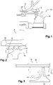
- abradable elements 18 The purpose of the abradable elements 18 is to protect the lips 12 from the risks of wear by contact with the stator element 16 which surrounds them. Contacts with the abradable elements 18 can be avoided or on the contrary sought for example to minimize the radial clearances J around the wipers.
- the types of abradable elements 18 and wipers 12 can be adapted accordingly.
- This technology can be used to seal the tips of the blades of a rotor wheel, these blades carrying annular wipers, possibly sectorized, which are surrounded by abradable elements carried by a stator casing (see in particular FR-A1-3 001 759 ). It can also be used to provide sealing between a shaft or journal portion and a stator of the turbomachine.
- the number and dimensions of the wipers are in particular a function of the radial space available between the elements to be sealed.
- the wipers 12 In operation, as shown in figures 2 and 3 , the wipers 12 have the function of disturbing the flow of gas which tries to flow between the elements 14, 16 from upstream to downstream, that is to say from left to right in the drawings. This creates turbulence in the gas flow which generates pressure drops and thus improves the tightness of the joint.
- the present invention proposes an improvement to this technology to improve the tightness of the gasket in a simple, efficient and economical manner.
- the invention proposes a labyrinth seal for a turbomachine according to claim 1.
- the present invention can use only two wipers to seal between a rotor and a stator. These wipers can replace a multitude of adjacent prior art annular wipers, which is advantageous.
- the air passage cavities are located between the wipers (or between two annular walls, respectively upstream and downstream, of the wiper when it is considered to be a single wiper) and are arranged circumferentially. They emerge radially outwards, facing the abradable element and are internally delimited by a bottom or an annular surface extending between the lips and which is preferably cylindrical.
- the gas flow is disturbed a first time when it impacts the body of the upstream wiper.
- the gas flow crosses the radial clearance at the top of the upstream wiper and penetrates and circulates in the cavities where it is disturbed a second time and can undergo various phenomena (disturbances, pressurization, vortices, etc.). These phenomena create turbulence which improves the performance of the seal.
- the flow of gas continues its course then is disrupted a third time due in particular to the increase in the passage section after crossing the downstream wiper.
- the invention thus makes it possible to significantly increase the level of tightness of the joint.
- said partitions can extend substantially axially between the wipers and define gas passage space sectors between them, said space sectors being cut out by separating walls to form said cavities
- the present invention also relates to a turbomachine, characterized in that it comprises at least one seal as described above.
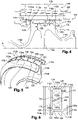
- the figures 4 to 6 represent a first embodiment of a labyrinth seal 100 for a turbomachine, in particular an aircraft.
- the joint 100 comprises a rotor element 114 rotating around an axis of rotation, which is not visible and which will be denoted by A, and a stator element 116 extending around the rotor element 114.
- stator element 116 is a turbine nozzle which comprises two annular shrouds between which extends an annular row of stator vanes 120. Only the radially inner shroud 122 is visible here.
- This shell has a generally cylindrical or frustoconical shape and carries on its internal periphery a abradable annular element 118 which surrounds with a small radial play J the rotor element 114.
- This rotor element 114 is here a rotor disk which can be in one piece, that is to say it extends continuously over 360° around its axis A. It comprises an annular wall 114a extending around the axis and perforated in its center. As is visible at the figure 5 , this wall has in section a "leek" shape, well known to those skilled in the art.
- the wall 114a is connected at its outer periphery to two annular flanges, respectively upstream 114b and downstream 114c.
- the upstream flange 114b has a curved general shape in axial section, the concavity of which is oriented radially outward with respect to the axis A.
- the flange 114b has a downstream end connected to the outer periphery of the wall 114a and an upstream end free which can be attached to a rotor wheel located upstream of the element 114.
- the downstream flange 114b also has in axial section a generally curved shape whose concavity is oriented radially outwards with respect to the axis A.
- Shroud 114c has an upstream end connected to the outer periphery of wall 114a and a free downstream end which can be attached to a rotor wheel located downstream of element 114.
- the outer periphery of the wall 114a is thickened both radially and axially in the example shown so as to define a radially outer cylindrical surface 122.
- This surface 122 here has an axial dimension L greater than the minimum axial thickness of the wall 114a and substantially equal to the maximum axial thickness of this wall ( figure 5 ).
- the outer periphery of the wall 114a also has a radial thickness E greater than the average radial thickness of the flanges 114b, 114c, which is for example measured at a distance from their axial ends.
- Two annular wipers 112a, 112b are formed projecting from surface 122 and extend radially outward. They are substantially parallel to each other and to a plane perpendicular to the axis A. They are located respectively at the axial ends of the surface 122.
- the upstream wiper 112a has an upstream radial face 112aa which is radially aligned with an upstream radial face 122a of the outer periphery of the wall 114a.
- the downstream wiper 112b has a downstream radial face 112ba which is radially aligned with a downstream radial face 122b of the outer periphery of the wall 114a.
- the radially outer tops or ends of the wipers are separated by the clearance J located between the rotor element 116 and the abradable element 118.
- the wipers 112a, 112b define between them an annular space 124 which is sectorized and formed of several space sectors 124a, 124b, etc. isolated and arranged circumferentially next to each other around axis A.
- the wipers 112a, 112b are connected to each other by partitions 126 which are here parallel to each other and oriented axially, that is to say parallel to the axis A. As can be seen in the figures 5 and 6 , the partitions 126 isolate the space sectors 124a, 124b from each other.
- the wipers 112a, 112b and the partitions 126 have the same height H1 or radial dimension, measured here from the cylindrical surface 122.
- the partitions 126 therefore have their vertices which are separated by the clearance J of the element abradable 118.
- the partitions 126 can be connected to the wipers 112a, 112b as well as to the surface 122 by fillets 126a ( figures 5 and 6 ).
- a sector of space 124a, 124b is thus delimited on the one hand by axially aligned portions of the lips 112a, 112b and on the other hand by two adjacent partitions 126 extending between these portions.
- Each sector of space thus has the shape of a “bathtub”.
- each space sector 124a, 124b is in fluid communication on the one hand upstream, via an opening 128 provided on the upstream wiper 112a, and on the other hand downstream, via an opening 130 provided on the downstream wiper 112b.
- the openings 128, 130 are here formed by radial notches extending from the tops of the lips over approximately all their heights.
- the openings 128, 130 are not aligned axially but are on the contrary offset from each other in the circumferential direction, as shown in figure 6 .
- the opening 128 can emerge near one of the circumferential ends of the space sector 124a, 124b, and the other opening 130 can emerge near the opposite circumferential end of this space sector.
- the opening 128 allows the passage of gas in operation, from upstream to downstream, along the arrow F4, therefore from the upstream of the upstream wiper 112a into the space sector 124a, 124b.
- the opening 130 allows the passage of gas in operation, from upstream to downstream, along the arrow F5, therefore from the space sector 124a, 124b to the downstream of the downstream wiper 112b.
- each space sector comprises a wall 132 which has a generally corrugated shape and comprises an upstream end connected to the downstream radial face of the upstream wiper 112a and a downstream end connected to the upstream radial face facing the downstream wiper 112b.
- the wall 132 is located substantially in the middle of the space sector, in the circumferential direction, and comprises a through hole 134 oriented here in the substantially circumferential direction.
- the wall 132 here has a radial height H2, measured from the surface 122, which is lower than that H1 of the wipers 112a, 112b and of the partitions 126.
- the wall 132 separates the space into two cavities 132a, 132b in fluid communication via the piercing 134.
- the shapes and dimensions of the wall 132 as well as of the bore 134 are determined to control the disturbances of the flow of gas entering and circulating in each sector of space.
- the openings 128, 130 are advantageously calibrated.
- the cavities 132a, 132b could lose their curvilinear side or reduce in spacing in places with the aim of increasing the pressure between two shapes in order to expel a more compressed flow of gas between the rotor and the stator.
- the shapes can be aerodynamic or on the contrary pointed to smooth the flow in places or amplify the disturbance in others (according to upstream/downstream needs).
- the flow of gas is disturbed a first time when it impacts the wiper (arrow F1).
- a first part of the gas flow crosses the radial play at the top of the wipers 112a, 112b (arrow F3) then is disturbed a second time following the increase in the passage section downstream of the wipers (arrow F2).
- a second part of the gas flow enters the space sectors 124a, 124b (arrow F4) and circulates there while being disturbed, which generates turbulence and impacts the first part of the gas flow, the flow rate of which is reduced.
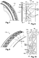
- each space sector comprises a large number of walls 132, for example greater than 5, which have complex shapes and delimit several cavities 132a, 132b, etc., the number of which may also be greater than 5.
- Some of the walls 132 comprise bores for the fluid communication of the cavities with each other and for the routing of the gas flow, from the opening 128 to the opening 130 of each space sector.
- the walls 132 here have a radial height identical to that of the wipers and the partitions.
- each space sector comprises a large number of walls 132, for example greater than 5, which each have a general volute shape and which each delimit a helical cavity 132c, the number of which may also be greater than 5.
- the space between the wipers 112a, 112b comprises two adjacent annular rows of volute walls 132.
- the walls 132 are not drilled here.
- only the upstream wiper 112a comprises openings 128, here three in number per space sector 124a, 124b.
- the downstream wiper 112b thus does not include any openings and the cavities 132c do not communicate fluidly with each other through holes in the walls 132.
- the gases which enter the cavities 132c through the openings 128 are forced to follow the volute or helix shape. which generates the formation of vortices in each sector of space, which disturbs and limits the flow of fluid according to the arrow F3 of the figure 4 .
Applications Claiming Priority (2)
| Application Number | Priority Date | Filing Date | Title |
|---|---|---|---|
| FR1855418A FR3082879B1 (fr) | 2018-06-20 | 2018-06-20 | Joint d'etancheite a labyrinthe pour une turbomachine d'aeronef |
| PCT/FR2019/051400 WO2019243708A2 (fr) | 2018-06-20 | 2019-06-11 | Joint d'etancheite a labyrinthe pour une turbomachine d'aeronef |
Publications (2)
| Publication Number | Publication Date |
|---|---|
| EP3810902A2 EP3810902A2 (fr) | 2021-04-28 |
| EP3810902B1 true EP3810902B1 (fr) | 2023-01-04 |
Family
ID=63080150
Family Applications (1)
| Application Number | Title | Priority Date | Filing Date |
|---|---|---|---|
| EP19795249.2A Active EP3810902B1 (fr) | 2018-06-20 | 2019-06-11 | Joint d'etancheite a labyrinthe pour une turbomachine d'aeronef |
Country Status (5)
| Country | Link |
|---|---|
| US (1) | US11692450B2 (zh) |
| EP (1) | EP3810902B1 (zh) |
| CN (1) | CN112437832B (zh) |
| FR (1) | FR3082879B1 (zh) |
| WO (1) | WO2019243708A2 (zh) |
Family Cites Families (12)
| Publication number | Priority date | Publication date | Assignee | Title |
|---|---|---|---|---|
| EP1018594B1 (en) * | 1999-01-06 | 2006-12-27 | General Electric Company | Wheelspace windage cover plate for a turbine |
| EP1413712A1 (de) * | 2002-10-21 | 2004-04-28 | Siemens Aktiengesellschaft | Turbinenschaufel mit Deckband und Dichtrippe |
| US8172232B2 (en) * | 2003-05-01 | 2012-05-08 | Advanced Technologies Group, Inc. | Non-contact seal for a gas turbine engine |
| US9200528B2 (en) * | 2012-09-11 | 2015-12-01 | General Electric Company | Swirl interruption seal teeth for seal assembly |
| JP6049385B2 (ja) * | 2012-10-04 | 2016-12-21 | 株式会社日立製作所 | 遠心圧縮機 |
| FR3001759B1 (fr) | 2013-02-07 | 2015-01-16 | Snecma | Rouge aubagee de turbomachine |
| JP5951890B2 (ja) * | 2013-04-03 | 2016-07-13 | 三菱重工業株式会社 | 回転機械 |
| EP2826961A1 (en) * | 2013-07-19 | 2015-01-21 | Alstom Technology Ltd | Turbomachine with reduced tip leakage flow |
| EP2924237B1 (en) * | 2014-03-25 | 2018-07-11 | Industria de Turbo Propulsores S.A. | Gas turbine rotor |
| US20170183971A1 (en) * | 2015-12-28 | 2017-06-29 | General Electric Company | Tip shrouded turbine rotor blades |
| US10648346B2 (en) * | 2016-07-06 | 2020-05-12 | General Electric Company | Shroud configurations for turbine rotor blades |
| JP2018048565A (ja) * | 2016-09-20 | 2018-03-29 | 株式会社東芝 | 軸流タービンシール装置 |
-
2018
- 2018-06-20 FR FR1855418A patent/FR3082879B1/fr active Active
-
2019
- 2019-06-11 CN CN201980045929.7A patent/CN112437832B/zh active Active
- 2019-06-11 EP EP19795249.2A patent/EP3810902B1/fr active Active
- 2019-06-11 WO PCT/FR2019/051400 patent/WO2019243708A2/fr unknown
- 2019-06-11 US US17/253,070 patent/US11692450B2/en active Active
Also Published As
| Publication number | Publication date |
|---|---|
| FR3082879B1 (fr) | 2020-07-03 |
| WO2019243708A2 (fr) | 2019-12-26 |
| WO2019243708A3 (fr) | 2020-02-20 |
| US11692450B2 (en) | 2023-07-04 |
| CN112437832A (zh) | 2021-03-02 |
| FR3082879A1 (fr) | 2019-12-27 |
| EP3810902A2 (fr) | 2021-04-28 |
| US20210215056A1 (en) | 2021-07-15 |
| CN112437832B (zh) | 2023-04-21 |
Similar Documents
| Publication | Publication Date | Title |
|---|---|---|
| EP1972757B1 (fr) | Ensemble rotatif d'une soufflante de turbomachine | |
| WO2012107676A1 (fr) | Ensemble pale-plateforme pour ecoulement subsonique | |
| EP3610176B1 (fr) | Ensemble comprenant un train d'engrenages epicycloïdal | |
| FR2977909A1 (fr) | Aube de rotor pour une turbomachine | |
| FR3039589A1 (fr) | Etage de turbomachine, en particulier de turbine basse-pression | |
| WO2014122403A1 (fr) | Roue aubagée de turbomachine | |
| WO2020148489A1 (fr) | Ensemble pour une turbomachine | |
| EP3810902B1 (fr) | Joint d'etancheite a labyrinthe pour une turbomachine d'aeronef | |
| CA2898864A1 (fr) | Aubage fixe de distribution de flux dans une turbomachine, comprenant une plate-forme interne a renforts integres, turbomachine et procede de fabrication associes | |
| EP3781791B1 (fr) | Distributeur de turbine pour turbomachine, comprenant un système passif de réintroduction de gaz de fuite dans une veine d'écoulement des gaz | |
| FR3107919A1 (fr) | Aube creuse de turbomachine et plateforme inter-aubes équipées de saillies perturbatrices de flux de refroidissement | |
| FR3066533B1 (fr) | Ensemble d'etancheite pour une turbomachine | |
| WO2019224463A1 (fr) | Secteur angulaire d'aubage de turbomachine avec etancheite entre secteurs | |
| EP4010562B1 (fr) | Aube mobile pour une roue d'une turbomachine d'aéronef, roue pour une turbomachine d'aéronef et turbomachine d'aéronef | |
| FR3071541B1 (fr) | Joint d'etancheite a labyrinthe pour une turbomachine d'aeronef | |
| EP3320186B1 (fr) | Ensemble pour turbine | |
| FR3100836A1 (fr) | Aubes mobiles pour turbine | |
| FR3049307B1 (fr) | Ensemble rotatif pour turbomachine | |
| EP3768950B1 (fr) | Disque aubagé monobloc souple en partie basse des aubes | |
| FR3069276B1 (fr) | Ensemble d'etancheite pour turbomachine | |
| FR3107920A1 (fr) | Aube creuse de turbomachine et plateforme inter-aubes équipées de saillies perturbatrices de flux de refroidissement | |
| FR2944554A1 (fr) | Turbine haute-pression de turbomachine | |
| FR3036753A1 (fr) | Cage annulaire de palier a roulement pour une turbomachine | |
| FR3136504A1 (fr) | Elément abradable pour une turbine de turbomachine, comprenant des alvéoles présentant différentes inclinaisons | |
| WO2023047034A1 (fr) | Turbine à gaz haute-pression pour une turbomachine et turbomachine |
Legal Events
| Date | Code | Title | Description |
|---|---|---|---|
| STAA | Information on the status of an ep patent application or granted ep patent |
Free format text: STATUS: UNKNOWN |
|
| STAA | Information on the status of an ep patent application or granted ep patent |
Free format text: STATUS: THE INTERNATIONAL PUBLICATION HAS BEEN MADE |
|
| STAA | Information on the status of an ep patent application or granted ep patent |
Free format text: STATUS: THE INTERNATIONAL PUBLICATION HAS BEEN MADE |
|
| PUAI | Public reference made under article 153(3) epc to a published international application that has entered the european phase |
Free format text: ORIGINAL CODE: 0009012 |
|
| STAA | Information on the status of an ep patent application or granted ep patent |
Free format text: STATUS: REQUEST FOR EXAMINATION WAS MADE |
|
| 17P | Request for examination filed |
Effective date: 20201222 |
|
| AK | Designated contracting states |
Kind code of ref document: A2 Designated state(s): AL AT BE BG CH CY CZ DE DK EE ES FI FR GB GR HR HU IE IS IT LI LT LU LV MC MK MT NL NO PL PT RO RS SE SI SK SM TR |
|
| AX | Request for extension of the european patent |
Extension state: BA ME |
|
| DAV | Request for validation of the european patent (deleted) | ||
| DAX | Request for extension of the european patent (deleted) | ||
| GRAP | Despatch of communication of intention to grant a patent |
Free format text: ORIGINAL CODE: EPIDOSNIGR1 |
|
| STAA | Information on the status of an ep patent application or granted ep patent |
Free format text: STATUS: GRANT OF PATENT IS INTENDED |
|
| RIC1 | Information provided on ipc code assigned before grant |
Ipc: F16J 15/44 20060101ALI20220927BHEP Ipc: F01D 11/02 20060101ALI20220927BHEP Ipc: F01D 11/00 20060101AFI20220927BHEP |
|
| INTG | Intention to grant announced |
Effective date: 20221021 |
|
| GRAS | Grant fee paid |
Free format text: ORIGINAL CODE: EPIDOSNIGR3 |
|
| GRAA | (expected) grant |
Free format text: ORIGINAL CODE: 0009210 |
|
| STAA | Information on the status of an ep patent application or granted ep patent |
Free format text: STATUS: THE PATENT HAS BEEN GRANTED |
|
| AK | Designated contracting states |
Kind code of ref document: B1 Designated state(s): AL AT BE BG CH CY CZ DE DK EE ES FI FR GB GR HR HU IE IS IT LI LT LU LV MC MK MT NL NO PL PT RO RS SE SI SK SM TR |
|
| REG | Reference to a national code |
Ref country code: GB Ref legal event code: FG4D Free format text: NOT ENGLISH |
|
| REG | Reference to a national code |
Ref country code: DE Ref legal event code: R096 Ref document number: 602019024030 Country of ref document: DE |
|
| REG | Reference to a national code |
Ref country code: CH Ref legal event code: EP |
|
| REG | Reference to a national code |
Ref country code: AT Ref legal event code: REF Ref document number: 1542056 Country of ref document: AT Kind code of ref document: T Effective date: 20230115 |
|
| REG | Reference to a national code |
Ref country code: IE Ref legal event code: FG4D Free format text: LANGUAGE OF EP DOCUMENT: FRENCH |
|
| REG | Reference to a national code |
Ref country code: LT Ref legal event code: MG9D |
|
| REG | Reference to a national code |
Ref country code: NL Ref legal event code: MP Effective date: 20230104 |
|
| REG | Reference to a national code |
Ref country code: AT Ref legal event code: MK05 Ref document number: 1542056 Country of ref document: AT Kind code of ref document: T Effective date: 20230104 |
|
| PG25 | Lapsed in a contracting state [announced via postgrant information from national office to epo] |
Ref country code: NL Free format text: LAPSE BECAUSE OF FAILURE TO SUBMIT A TRANSLATION OF THE DESCRIPTION OR TO PAY THE FEE WITHIN THE PRESCRIBED TIME-LIMIT Effective date: 20230104 |
|
| PG25 | Lapsed in a contracting state [announced via postgrant information from national office to epo] |
Ref country code: RS Free format text: LAPSE BECAUSE OF FAILURE TO SUBMIT A TRANSLATION OF THE DESCRIPTION OR TO PAY THE FEE WITHIN THE PRESCRIBED TIME-LIMIT Effective date: 20230104 Ref country code: PT Free format text: LAPSE BECAUSE OF FAILURE TO SUBMIT A TRANSLATION OF THE DESCRIPTION OR TO PAY THE FEE WITHIN THE PRESCRIBED TIME-LIMIT Effective date: 20230504 Ref country code: NO Free format text: LAPSE BECAUSE OF FAILURE TO SUBMIT A TRANSLATION OF THE DESCRIPTION OR TO PAY THE FEE WITHIN THE PRESCRIBED TIME-LIMIT Effective date: 20230404 Ref country code: LV Free format text: LAPSE BECAUSE OF FAILURE TO SUBMIT A TRANSLATION OF THE DESCRIPTION OR TO PAY THE FEE WITHIN THE PRESCRIBED TIME-LIMIT Effective date: 20230104 Ref country code: LT Free format text: LAPSE BECAUSE OF FAILURE TO SUBMIT A TRANSLATION OF THE DESCRIPTION OR TO PAY THE FEE WITHIN THE PRESCRIBED TIME-LIMIT Effective date: 20230104 Ref country code: HR Free format text: LAPSE BECAUSE OF FAILURE TO SUBMIT A TRANSLATION OF THE DESCRIPTION OR TO PAY THE FEE WITHIN THE PRESCRIBED TIME-LIMIT Effective date: 20230104 Ref country code: ES Free format text: LAPSE BECAUSE OF FAILURE TO SUBMIT A TRANSLATION OF THE DESCRIPTION OR TO PAY THE FEE WITHIN THE PRESCRIBED TIME-LIMIT Effective date: 20230104 Ref country code: AT Free format text: LAPSE BECAUSE OF FAILURE TO SUBMIT A TRANSLATION OF THE DESCRIPTION OR TO PAY THE FEE WITHIN THE PRESCRIBED TIME-LIMIT Effective date: 20230104 |
|
| PGFP | Annual fee paid to national office [announced via postgrant information from national office to epo] |
Ref country code: FR Payment date: 20230523 Year of fee payment: 5 Ref country code: DE Payment date: 20230523 Year of fee payment: 5 |
|
| PG25 | Lapsed in a contracting state [announced via postgrant information from national office to epo] |
Ref country code: SE Free format text: LAPSE BECAUSE OF FAILURE TO SUBMIT A TRANSLATION OF THE DESCRIPTION OR TO PAY THE FEE WITHIN THE PRESCRIBED TIME-LIMIT Effective date: 20230104 Ref country code: PL Free format text: LAPSE BECAUSE OF FAILURE TO SUBMIT A TRANSLATION OF THE DESCRIPTION OR TO PAY THE FEE WITHIN THE PRESCRIBED TIME-LIMIT Effective date: 20230104 Ref country code: IS Free format text: LAPSE BECAUSE OF FAILURE TO SUBMIT A TRANSLATION OF THE DESCRIPTION OR TO PAY THE FEE WITHIN THE PRESCRIBED TIME-LIMIT Effective date: 20230504 Ref country code: GR Free format text: LAPSE BECAUSE OF FAILURE TO SUBMIT A TRANSLATION OF THE DESCRIPTION OR TO PAY THE FEE WITHIN THE PRESCRIBED TIME-LIMIT Effective date: 20230405 Ref country code: FI Free format text: LAPSE BECAUSE OF FAILURE TO SUBMIT A TRANSLATION OF THE DESCRIPTION OR TO PAY THE FEE WITHIN THE PRESCRIBED TIME-LIMIT Effective date: 20230104 |
|
| REG | Reference to a national code |
Ref country code: DE Ref legal event code: R097 Ref document number: 602019024030 Country of ref document: DE |
|
| PG25 | Lapsed in a contracting state [announced via postgrant information from national office to epo] |
Ref country code: SM Free format text: LAPSE BECAUSE OF FAILURE TO SUBMIT A TRANSLATION OF THE DESCRIPTION OR TO PAY THE FEE WITHIN THE PRESCRIBED TIME-LIMIT Effective date: 20230104 Ref country code: RO Free format text: LAPSE BECAUSE OF FAILURE TO SUBMIT A TRANSLATION OF THE DESCRIPTION OR TO PAY THE FEE WITHIN THE PRESCRIBED TIME-LIMIT Effective date: 20230104 Ref country code: EE Free format text: LAPSE BECAUSE OF FAILURE TO SUBMIT A TRANSLATION OF THE DESCRIPTION OR TO PAY THE FEE WITHIN THE PRESCRIBED TIME-LIMIT Effective date: 20230104 Ref country code: DK Free format text: LAPSE BECAUSE OF FAILURE TO SUBMIT A TRANSLATION OF THE DESCRIPTION OR TO PAY THE FEE WITHIN THE PRESCRIBED TIME-LIMIT Effective date: 20230104 Ref country code: CZ Free format text: LAPSE BECAUSE OF FAILURE TO SUBMIT A TRANSLATION OF THE DESCRIPTION OR TO PAY THE FEE WITHIN THE PRESCRIBED TIME-LIMIT Effective date: 20230104 |
|
| PGFP | Annual fee paid to national office [announced via postgrant information from national office to epo] |
Ref country code: GB Payment date: 20230523 Year of fee payment: 5 |
|
| PLBE | No opposition filed within time limit |
Free format text: ORIGINAL CODE: 0009261 |
|
| STAA | Information on the status of an ep patent application or granted ep patent |
Free format text: STATUS: NO OPPOSITION FILED WITHIN TIME LIMIT |
|
| PG25 | Lapsed in a contracting state [announced via postgrant information from national office to epo] |
Ref country code: SK Free format text: LAPSE BECAUSE OF FAILURE TO SUBMIT A TRANSLATION OF THE DESCRIPTION OR TO PAY THE FEE WITHIN THE PRESCRIBED TIME-LIMIT Effective date: 20230104 |
|
| 26N | No opposition filed |
Effective date: 20231005 |
|
| PG25 | Lapsed in a contracting state [announced via postgrant information from national office to epo] |
Ref country code: MC Free format text: LAPSE BECAUSE OF FAILURE TO SUBMIT A TRANSLATION OF THE DESCRIPTION OR TO PAY THE FEE WITHIN THE PRESCRIBED TIME-LIMIT Effective date: 20230104 |
|
| PG25 | Lapsed in a contracting state [announced via postgrant information from national office to epo] |
Ref country code: SI Free format text: LAPSE BECAUSE OF FAILURE TO SUBMIT A TRANSLATION OF THE DESCRIPTION OR TO PAY THE FEE WITHIN THE PRESCRIBED TIME-LIMIT Effective date: 20230104 Ref country code: MC Free format text: LAPSE BECAUSE OF FAILURE TO SUBMIT A TRANSLATION OF THE DESCRIPTION OR TO PAY THE FEE WITHIN THE PRESCRIBED TIME-LIMIT Effective date: 20230104 |
|
| REG | Reference to a national code |
Ref country code: CH Ref legal event code: PL |
|
| REG | Reference to a national code |
Ref country code: BE Ref legal event code: MM Effective date: 20230630 |
|
| PG25 | Lapsed in a contracting state [announced via postgrant information from national office to epo] |
Ref country code: LU Free format text: LAPSE BECAUSE OF NON-PAYMENT OF DUE FEES Effective date: 20230611 |
|
| REG | Reference to a national code |
Ref country code: IE Ref legal event code: MM4A |
|
| PG25 | Lapsed in a contracting state [announced via postgrant information from national office to epo] |
Ref country code: LU Free format text: LAPSE BECAUSE OF NON-PAYMENT OF DUE FEES Effective date: 20230611 |
|
| PG25 | Lapsed in a contracting state [announced via postgrant information from national office to epo] |
Ref country code: IE Free format text: LAPSE BECAUSE OF NON-PAYMENT OF DUE FEES Effective date: 20230611 |