EP3810902B1 - Labyrinth seal for a turbomachine of an aircraft - Google Patents
Labyrinth seal for a turbomachine of an aircraft Download PDFInfo
- Publication number
- EP3810902B1 EP3810902B1 EP19795249.2A EP19795249A EP3810902B1 EP 3810902 B1 EP3810902 B1 EP 3810902B1 EP 19795249 A EP19795249 A EP 19795249A EP 3810902 B1 EP3810902 B1 EP 3810902B1
- Authority
- EP
- European Patent Office
- Prior art keywords
- lips
- sealing joint
- gas passage
- upstream
- cavities
- Prior art date
- Legal status (The legal status is an assumption and is not a legal conclusion. Google has not performed a legal analysis and makes no representation as to the accuracy of the status listed.)
- Active
Links
- 238000011144 upstream manufacturing Methods 0.000 claims description 35
- 238000005192 partition Methods 0.000 claims description 15
- 238000007789 sealing Methods 0.000 claims description 11
- 238000000926 separation method Methods 0.000 claims description 5
- 239000007789 gas Substances 0.000 description 26
- 239000012530 fluid Substances 0.000 description 4
- 238000004891 communication Methods 0.000 description 3
- 238000012550 audit Methods 0.000 description 2
- 210000004027 cell Anatomy 0.000 description 2
- 238000005516 engineering process Methods 0.000 description 2
- 240000006108 Allium ampeloprasum Species 0.000 description 1
- 235000005254 Allium ampeloprasum Nutrition 0.000 description 1
- 230000015572 biosynthetic process Effects 0.000 description 1
- 239000011248 coating agent Substances 0.000 description 1
- 238000000576 coating method Methods 0.000 description 1
- 239000000463 material Substances 0.000 description 1
- 238000000034 method Methods 0.000 description 1
Images
Classifications
-
- F—MECHANICAL ENGINEERING; LIGHTING; HEATING; WEAPONS; BLASTING
- F01—MACHINES OR ENGINES IN GENERAL; ENGINE PLANTS IN GENERAL; STEAM ENGINES
- F01D—NON-POSITIVE DISPLACEMENT MACHINES OR ENGINES, e.g. STEAM TURBINES
- F01D11/00—Preventing or minimising internal leakage of working-fluid, e.g. between stages
- F01D11/02—Preventing or minimising internal leakage of working-fluid, e.g. between stages by non-contact sealings, e.g. of labyrinth type
-
- F—MECHANICAL ENGINEERING; LIGHTING; HEATING; WEAPONS; BLASTING
- F01—MACHINES OR ENGINES IN GENERAL; ENGINE PLANTS IN GENERAL; STEAM ENGINES
- F01D—NON-POSITIVE DISPLACEMENT MACHINES OR ENGINES, e.g. STEAM TURBINES
- F01D11/00—Preventing or minimising internal leakage of working-fluid, e.g. between stages
- F01D11/001—Preventing or minimising internal leakage of working-fluid, e.g. between stages for sealing space between stator blade and rotor
-
- F—MECHANICAL ENGINEERING; LIGHTING; HEATING; WEAPONS; BLASTING
- F05—INDEXING SCHEMES RELATING TO ENGINES OR PUMPS IN VARIOUS SUBCLASSES OF CLASSES F01-F04
- F05D—INDEXING SCHEME FOR ASPECTS RELATING TO NON-POSITIVE-DISPLACEMENT MACHINES OR ENGINES, GAS-TURBINES OR JET-PROPULSION PLANTS
- F05D2220/00—Application
- F05D2220/30—Application in turbines
- F05D2220/32—Application in turbines in gas turbines
- F05D2220/323—Application in turbines in gas turbines for aircraft propulsion, e.g. jet engines
-
- F—MECHANICAL ENGINEERING; LIGHTING; HEATING; WEAPONS; BLASTING
- F05—INDEXING SCHEMES RELATING TO ENGINES OR PUMPS IN VARIOUS SUBCLASSES OF CLASSES F01-F04
- F05D—INDEXING SCHEME FOR ASPECTS RELATING TO NON-POSITIVE-DISPLACEMENT MACHINES OR ENGINES, GAS-TURBINES OR JET-PROPULSION PLANTS
- F05D2240/00—Components
- F05D2240/55—Seals
-
- F—MECHANICAL ENGINEERING; LIGHTING; HEATING; WEAPONS; BLASTING
- F16—ENGINEERING ELEMENTS AND UNITS; GENERAL MEASURES FOR PRODUCING AND MAINTAINING EFFECTIVE FUNCTIONING OF MACHINES OR INSTALLATIONS; THERMAL INSULATION IN GENERAL
- F16J—PISTONS; CYLINDERS; SEALINGS
- F16J15/00—Sealings
- F16J15/44—Free-space packings
- F16J15/444—Free-space packings with facing materials having honeycomb-like structure
Definitions
- the present invention relates to a labyrinth seal for a turbomachine, in particular an aircraft.
- the state of the art includes in particular the documents EP-A1-1413712 , US-A1-2018/010467 and US-A1-2014/072415 .
- abradable elements 18 The purpose of the abradable elements 18 is to protect the lips 12 from the risks of wear by contact with the stator element 16 which surrounds them. Contacts with the abradable elements 18 can be avoided or on the contrary sought for example to minimize the radial clearances J around the wipers.
- the types of abradable elements 18 and wipers 12 can be adapted accordingly.
- This technology can be used to seal the tips of the blades of a rotor wheel, these blades carrying annular wipers, possibly sectorized, which are surrounded by abradable elements carried by a stator casing (see in particular FR-A1-3 001 759 ). It can also be used to provide sealing between a shaft or journal portion and a stator of the turbomachine.
- the number and dimensions of the wipers are in particular a function of the radial space available between the elements to be sealed.
- the wipers 12 In operation, as shown in figures 2 and 3 , the wipers 12 have the function of disturbing the flow of gas which tries to flow between the elements 14, 16 from upstream to downstream, that is to say from left to right in the drawings. This creates turbulence in the gas flow which generates pressure drops and thus improves the tightness of the joint.
- the present invention proposes an improvement to this technology to improve the tightness of the gasket in a simple, efficient and economical manner.
- the invention proposes a labyrinth seal for a turbomachine according to claim 1.
- the present invention can use only two wipers to seal between a rotor and a stator. These wipers can replace a multitude of adjacent prior art annular wipers, which is advantageous.
- the air passage cavities are located between the wipers (or between two annular walls, respectively upstream and downstream, of the wiper when it is considered to be a single wiper) and are arranged circumferentially. They emerge radially outwards, facing the abradable element and are internally delimited by a bottom or an annular surface extending between the lips and which is preferably cylindrical.
- the gas flow is disturbed a first time when it impacts the body of the upstream wiper.
- the gas flow crosses the radial clearance at the top of the upstream wiper and penetrates and circulates in the cavities where it is disturbed a second time and can undergo various phenomena (disturbances, pressurization, vortices, etc.). These phenomena create turbulence which improves the performance of the seal.
- the flow of gas continues its course then is disrupted a third time due in particular to the increase in the passage section after crossing the downstream wiper.
- the invention thus makes it possible to significantly increase the level of tightness of the joint.
- said partitions can extend substantially axially between the wipers and define gas passage space sectors between them, said space sectors being cut out by separating walls to form said cavities
- the present invention also relates to a turbomachine, characterized in that it comprises at least one seal as described above.
- the figures 4 to 6 represent a first embodiment of a labyrinth seal 100 for a turbomachine, in particular an aircraft.
- the joint 100 comprises a rotor element 114 rotating around an axis of rotation, which is not visible and which will be denoted by A, and a stator element 116 extending around the rotor element 114.
- stator element 116 is a turbine nozzle which comprises two annular shrouds between which extends an annular row of stator vanes 120. Only the radially inner shroud 122 is visible here.
- This shell has a generally cylindrical or frustoconical shape and carries on its internal periphery a abradable annular element 118 which surrounds with a small radial play J the rotor element 114.
- This rotor element 114 is here a rotor disk which can be in one piece, that is to say it extends continuously over 360° around its axis A. It comprises an annular wall 114a extending around the axis and perforated in its center. As is visible at the figure 5 , this wall has in section a "leek" shape, well known to those skilled in the art.
- the wall 114a is connected at its outer periphery to two annular flanges, respectively upstream 114b and downstream 114c.
- the upstream flange 114b has a curved general shape in axial section, the concavity of which is oriented radially outward with respect to the axis A.
- the flange 114b has a downstream end connected to the outer periphery of the wall 114a and an upstream end free which can be attached to a rotor wheel located upstream of the element 114.
- the downstream flange 114b also has in axial section a generally curved shape whose concavity is oriented radially outwards with respect to the axis A.
- Shroud 114c has an upstream end connected to the outer periphery of wall 114a and a free downstream end which can be attached to a rotor wheel located downstream of element 114.
- the outer periphery of the wall 114a is thickened both radially and axially in the example shown so as to define a radially outer cylindrical surface 122.
- This surface 122 here has an axial dimension L greater than the minimum axial thickness of the wall 114a and substantially equal to the maximum axial thickness of this wall ( figure 5 ).
- the outer periphery of the wall 114a also has a radial thickness E greater than the average radial thickness of the flanges 114b, 114c, which is for example measured at a distance from their axial ends.
- Two annular wipers 112a, 112b are formed projecting from surface 122 and extend radially outward. They are substantially parallel to each other and to a plane perpendicular to the axis A. They are located respectively at the axial ends of the surface 122.
- the upstream wiper 112a has an upstream radial face 112aa which is radially aligned with an upstream radial face 122a of the outer periphery of the wall 114a.
- the downstream wiper 112b has a downstream radial face 112ba which is radially aligned with a downstream radial face 122b of the outer periphery of the wall 114a.
- the radially outer tops or ends of the wipers are separated by the clearance J located between the rotor element 116 and the abradable element 118.
- the wipers 112a, 112b define between them an annular space 124 which is sectorized and formed of several space sectors 124a, 124b, etc. isolated and arranged circumferentially next to each other around axis A.
- the wipers 112a, 112b are connected to each other by partitions 126 which are here parallel to each other and oriented axially, that is to say parallel to the axis A. As can be seen in the figures 5 and 6 , the partitions 126 isolate the space sectors 124a, 124b from each other.
- the wipers 112a, 112b and the partitions 126 have the same height H1 or radial dimension, measured here from the cylindrical surface 122.
- the partitions 126 therefore have their vertices which are separated by the clearance J of the element abradable 118.
- the partitions 126 can be connected to the wipers 112a, 112b as well as to the surface 122 by fillets 126a ( figures 5 and 6 ).
- a sector of space 124a, 124b is thus delimited on the one hand by axially aligned portions of the lips 112a, 112b and on the other hand by two adjacent partitions 126 extending between these portions.
- Each sector of space thus has the shape of a “bathtub”.
- each space sector 124a, 124b is in fluid communication on the one hand upstream, via an opening 128 provided on the upstream wiper 112a, and on the other hand downstream, via an opening 130 provided on the downstream wiper 112b.
- the openings 128, 130 are here formed by radial notches extending from the tops of the lips over approximately all their heights.
- the openings 128, 130 are not aligned axially but are on the contrary offset from each other in the circumferential direction, as shown in figure 6 .
- the opening 128 can emerge near one of the circumferential ends of the space sector 124a, 124b, and the other opening 130 can emerge near the opposite circumferential end of this space sector.
- the opening 128 allows the passage of gas in operation, from upstream to downstream, along the arrow F4, therefore from the upstream of the upstream wiper 112a into the space sector 124a, 124b.
- the opening 130 allows the passage of gas in operation, from upstream to downstream, along the arrow F5, therefore from the space sector 124a, 124b to the downstream of the downstream wiper 112b.
- each space sector comprises a wall 132 which has a generally corrugated shape and comprises an upstream end connected to the downstream radial face of the upstream wiper 112a and a downstream end connected to the upstream radial face facing the downstream wiper 112b.
- the wall 132 is located substantially in the middle of the space sector, in the circumferential direction, and comprises a through hole 134 oriented here in the substantially circumferential direction.
- the wall 132 here has a radial height H2, measured from the surface 122, which is lower than that H1 of the wipers 112a, 112b and of the partitions 126.
- the wall 132 separates the space into two cavities 132a, 132b in fluid communication via the piercing 134.
- the shapes and dimensions of the wall 132 as well as of the bore 134 are determined to control the disturbances of the flow of gas entering and circulating in each sector of space.
- the openings 128, 130 are advantageously calibrated.
- the cavities 132a, 132b could lose their curvilinear side or reduce in spacing in places with the aim of increasing the pressure between two shapes in order to expel a more compressed flow of gas between the rotor and the stator.
- the shapes can be aerodynamic or on the contrary pointed to smooth the flow in places or amplify the disturbance in others (according to upstream/downstream needs).
- the flow of gas is disturbed a first time when it impacts the wiper (arrow F1).
- a first part of the gas flow crosses the radial play at the top of the wipers 112a, 112b (arrow F3) then is disturbed a second time following the increase in the passage section downstream of the wipers (arrow F2).
- a second part of the gas flow enters the space sectors 124a, 124b (arrow F4) and circulates there while being disturbed, which generates turbulence and impacts the first part of the gas flow, the flow rate of which is reduced.
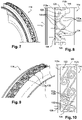
- each space sector comprises a large number of walls 132, for example greater than 5, which have complex shapes and delimit several cavities 132a, 132b, etc., the number of which may also be greater than 5.
- Some of the walls 132 comprise bores for the fluid communication of the cavities with each other and for the routing of the gas flow, from the opening 128 to the opening 130 of each space sector.
- the walls 132 here have a radial height identical to that of the wipers and the partitions.
- each space sector comprises a large number of walls 132, for example greater than 5, which each have a general volute shape and which each delimit a helical cavity 132c, the number of which may also be greater than 5.
- the space between the wipers 112a, 112b comprises two adjacent annular rows of volute walls 132.
- the walls 132 are not drilled here.
- only the upstream wiper 112a comprises openings 128, here three in number per space sector 124a, 124b.
- the downstream wiper 112b thus does not include any openings and the cavities 132c do not communicate fluidly with each other through holes in the walls 132.
- the gases which enter the cavities 132c through the openings 128 are forced to follow the volute or helix shape. which generates the formation of vortices in each sector of space, which disturbs and limits the flow of fluid according to the arrow F3 of the figure 4 .
Landscapes
- Engineering & Computer Science (AREA)
- General Engineering & Computer Science (AREA)
- Mechanical Engineering (AREA)
- Sealing Using Fluids, Sealing Without Contact, And Removal Of Oil (AREA)
- Turbine Rotor Nozzle Sealing (AREA)
Description
La présente invention concerne un joint d'étanchéité à labyrinthe pour une turbomachine, en particulier d'aéronef.The present invention relates to a labyrinth seal for a turbomachine, in particular an aircraft.
L'état de la technique comprend notamment les documents
Il est connu d'équiper une turbomachine de joints d'étanchéité à labyrinthe qui sont des joints d'étanchéité dont l'étanchéité dynamique est assurée par des léchettes tournantes. Comme cela est représenté à la
Les éléments abradables 18 ont pour but de protéger les léchettes 12 des risques d'usure par contact avec l'élément de stator 16 qui les entoure. Les contacts avec les éléments abradables 18 peuvent être évités ou au contraire recherchés par exemple pour minimiser les jeux radiaux J autour des léchettes. Les types d'éléments abradables 18 et de léchettes 12 peuvent être adaptés en conséquence.The purpose of the
Cette technologie peut être utilisée pour assurer une étanchéité aux sommets des aubes d'une roue de rotor, ces aubes portant des léchettes annulaires, éventuellement sectorisées, qui sont entourées par des éléments abradables portés par un carter de stator (voir notamment
En fonctionnement, comme cela est représenté aux
Au niveau de chaque léchette 12 à franchir, le flux de gaz est perturbé une première fois lorsqu'il impacte le corps de la léchette (flèche F1). Le flux de gaz franchit le jeu entre le sommet de la léchette 12 et l'élément abradable 18 qui l'entoure, ce flux étant réduit de la valeur J grâce à la perturbation créée par la léchette, puis est perturbé une seconde fois (flèche F2) suite à l'augmentation brusque de la section de passage après traversée de la léchette. Plus le nombre de léchettes 12 est important, plus cela génère de turbulences dans le flux de gaz, et plus l'étanchéité du joint est améliorée.At each
La présente invention propose un perfectionnement à cette technologie pour améliorer l'étanchéité du joint d'étanchéité de façon simple, efficace et économique.The present invention proposes an improvement to this technology to improve the tightness of the gasket in a simple, efficient and economical manner.
L'invention propose un joint d'étanchéité à labyrinthe pour une turbomachine selon la revendication 1.The invention proposes a labyrinth seal for a turbomachine according to claim 1.
La présente invention peut utiliser seulement deux léchettes pour assurer l'étanchéité entre un rotor et un stator. Ces léchettes peuvent remplacer une multitude de léchettes annulaires adjacentes de la technique antérieure, ce qui est avantageux.The present invention can use only two wipers to seal between a rotor and a stator. These wipers can replace a multitude of adjacent prior art annular wipers, which is advantageous.
Les cavités de passage d'air sont situées entre les léchettes (ou entre deux parois annulaires, respectivement amont et aval, de la léchette lorsqu'on considère qu'elle est unique) et sont disposées circonférentiellement. Elles débouchent radialement vers l'extérieur, en regard de l'élément abradable et sont délimitées intérieurement par un fond ou une surface annulaire s'étendant entre les léchettes et qui est de préférence cylindrique.The air passage cavities are located between the wipers (or between two annular walls, respectively upstream and downstream, of the wiper when it is considered to be a single wiper) and are arranged circumferentially. They emerge radially outwards, facing the abradable element and are internally delimited by a bottom or an annular surface extending between the lips and which is preferably cylindrical.
Ces cavités définissent ou font partie de « baignoires » dans lesquelles des flux de gaz peuvent circuler et sont avantageusement perturbés ou pressurisés.These cavities define or form part of “bathtubs” in which gas flows can circulate and are advantageously disturbed or pressurized.
Au niveau de chaque léchette à franchir, le flux de gaz est perturbé une première fois lorsqu'il impacte le corps de la léchette amont. Le flux de gaz franchit le jeu radial au sommet de la léchette amont et pénètre et circule dans les cavités où il est perturbé une seconde fois et peut subir divers phénomènes (perturbations, pressurisation, tourbillons, etc.). Ces phénomènes créent des turbulences qui améliorent les performances du joint d'étanchéité. Le flux de gaz poursuit sa course puis est perturbé une troisième fois du fait notamment de l'augmentation de la section de passage après traversée de la léchette aval.At each wiper to be crossed, the gas flow is disturbed a first time when it impacts the body of the upstream wiper. The gas flow crosses the radial clearance at the top of the upstream wiper and penetrates and circulates in the cavities where it is disturbed a second time and can undergo various phenomena (disturbances, pressurization, vortices, etc.). These phenomena create turbulence which improves the performance of the seal. The flow of gas continues its course then is disrupted a third time due in particular to the increase in the passage section after crossing the downstream wiper.
L'invention permet ainsi d'augmenter de manière significative le niveau d'étanchéité du joint.The invention thus makes it possible to significantly increase the level of tightness of the joint.
Conformément à l'invention, lesdites cloisons peuvent s'étendre sensiblement axialement entre les léchettes et définir entre elles des secteurs d'espace de passage de gaz, lesdits secteurs d'espace étant découpés par des parois de séparation pour former lesdites cavitésAccording to the invention, said partitions can extend substantially axially between the wipers and define gas passage space sectors between them, said space sectors being cut out by separating walls to form said cavities
Le joint selon l'invention peut comprendre une ou plusieurs des caractéristiques suivantes, prises isolément les unes des autres ou en combinaison les unes avec les autres :
- ledit élément de rotor est monobloc,
- au moins une des cavités est formée par plusieurs parois de séparation qui l'entourent,
- lesdites parois de séparation ont une hauteur ou dimension radiale par rapport audit axe au plus égale à celle desdites léchettes,
- lesdites léchettes et lesdites cloisons ont une même hauteur ou dimension radiale par rapport audit axe,
- lesdites léchettes comprennent une léchette amont et une léchette aval, la léchette amont comportant seule des ouvertures axiales de passage de gaz qui débouchent dans des cavités ou secteurs d'espace, ou les léchettes amont et aval comportant toutes les deux des ouvertures axiales de passage de gaz qui débouchent dans des cavités ou secteurs d'espace,
- la léchette amont comprend au moins une, de préférence une à trois, ouvertures de passage de gaz, qui débouche dans chaque cavité ou secteur d'espace,
- la léchette amont comprend une seule ouverture de passage de gaz qui débouche dans chaque cavité ou secteur d'espace, et la léchette aval comprend une seule ouverture de passage de gaz qui débouche dans chaque cavité ou secteur d'espace, ces ouvertures étant circonférentiellement décalées l'une de l'autre,
- ledit élément de rotor comprend un disque dont la périphérie externe est reliée à deux flasques annulaires, respectivement amont et aval, cette périphérie externe comportant une surface cylindrique externe sur lesquelles sont formées en saillie lesdites léchettes.
- said rotor element is one-piece,
- at least one of the cavities is formed by several dividing walls which surround it,
- said partition walls have a height or radial dimension with respect to said axis at most equal to that of said wipers,
- said wipers and said partitions have the same height or radial dimension with respect to said axis,
- said wipers comprise an upstream wiper and a downstream wiper, the upstream wiper alone comprising axial gas passage openings which open into cavities or sectors of space, or the upstream and downstream wipers both comprising axial gas passage openings gases which emerge in cavities or sectors of space,
- the upstream wiper comprises at least one, preferably one to three, gas passage openings, which opens into each cavity or space sector,
- the upstream wiper comprises a single gas passage opening which opens into each cavity or space sector, and the downstream wiper comprises a single gas passage opening which opens into each cavity or space sector, these openings being circumferentially offset one from the other,
- said rotor element comprises a disc whose outer periphery is connected to two annular flanges, respectively upstream and downstream, this outer periphery comprising an outer cylindrical surface on which said wipers are formed projecting.
La présente invention concerne encore une turbomachine, caractérisée en ce qu'elle comprend au moins un joint tel que décrit cidessus.The present invention also relates to a turbomachine, characterized in that it comprises at least one seal as described above.
L'invention sera mieux comprise et d'autres détails, caractéristiques et avantages de l'invention apparaîtront plus clairement à la lecture de la description suivante faite à titre d'exemple non limitatif et en référence aux dessins annexés dans lesquels :
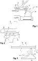
- la
figure 1 est une demi-vue schématique en coupe axiale d'un joint d'étanchéité à labyrinthe de turbomachine, selon la technique antérieure ; - les
figures 2 et 3 sont des vues schématiques à plus grandes échelles de détails de lafigure 1 ; - la
figure 4 est une demi-vue schématique partielle en coupe axiale d'un joint d'étanchéité à labyrinthe de turbomachine, selon l'invention ; - la
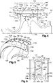
figure 5 est une vue schématique en perspective et en coupe axiale d'un élément de rotor du joint de lafigure 4 ; - la
figure 6 est une vue schématique de dessus de l'élément de rotor du joint de lafigure 4 ; - les
figures 7 et 8 sont des vues similaires à celles desfigures 5 et 6 et illustrant une variante de réalisation de l'invention ; et - les
figures 9 et 10 sont des vues similaires à celles desfigures 5 et 6 et illustrant une autre variante de réalisation de l'invention.
- the
figure 1 is a diagrammatic half-view in axial section of a turbomachine labyrinth seal, according to the prior art; - them
figures 2 and 3 are schematic views on larger scales of details of thefigure 1 ; - the
figure 4 is a partial schematic half-view in axial section of a turbomachine labyrinth seal, according to the invention; - the
figure 5 is a schematic view in perspective and in axial section of a rotor element of the seal of thefigure 4 ; - the
figure 6 is a schematic top view of the seal rotor element of thefigure 4 ; - them
figures 7 and 8 are views similar to those offigures 5 and 6 and illustrating a variant embodiment of the invention; and - them
figures 9 and 10 are views similar to those offigures 5 and 6 and illustrating another alternative embodiment of the invention.
Les
Les
Le joint 100 comporte un élément de rotor 114 tournant autour d'un axe de rotation, qui n'est pas visible et qui sera désigné par A, et un élément de stator 116 s'étendant autour de l'élément de rotor 114.The joint 100 comprises a
Dans l'exemple représenté, l'élément de stator 116 est un distributeur de turbine qui comprend deux viroles annulaires entre lesquelles s'étend une rangée annulaire d'aubes de stator 120. Seule la virole radialement interne 122 est ici visible. Cette virole a une forme générale cylindrique ou tronconique et porte à sa périphérie interne un élément annulaire abradable 118 qui entoure avec un faible jeu radial J l'élément de rotor 114.In the example shown, the
Cet élément de rotor 114 est ici un disque de rotor qui peut être monobloc c'est-à-dire qu'il s'étend en continu sur 360° autour de son axe A. Il comprend une paroi annulaire 114a s'étendant autour de l'axe et ajourée en son centre. Comme cela est visible à la
La paroi 114a est reliée à sa périphérie externe à deux flasques annulaires, respectivement amont 114b et aval 114c. Le flasque amont 114b a en section axiale une forme générale incurvée dont la concavité est orientée radialement vers l'extérieur par rapport à l'axe A. Le flasque 114b a une extrémité aval reliée à la périphérie externe de la paroi 114a et une extrémité amont libre qui peut être fixée à une roue de rotor située à l'amont de l'élément 114. Le flasque aval 114b a également en section axiale une forme générale incurvée dont la concavité est orientée radialement vers l'extérieur par rapport à l'axe A. Le flasque 114c a une extrémité amont reliée à la périphérie externe de la paroi 114a et une extrémité aval libre qui peut être fixée à une roue de rotor située à l'aval de l'élément 114.The
La périphérie externe de la paroi 114a est surépaissie autant radialement que axialement dans l'exemple représenté de façon à définir une surface cylindrique radialement externe 122. Cette surface 122 a ici une dimension axiale L supérieure à l'épaisseur axiale minimale de la paroi 114a et sensiblement égale à l'épaisseur axiale maximale de cette paroi (
Deux léchettes annulaires 112a, 112b sont formées en saillie sur la surface 122 et s'étendent radialement vers l'extérieur. Elles sont sensiblement parallèles entre elles et à un plan perpendiculaire à l'axe A. Elles sont situées respectivement aux extrémités axiales de la surface 122. La léchette amont 112a a une face radiale amont 112aa qui est alignée radialement avec une face radiale amont 122a de la périphérie externe de la paroi 114a. La léchette aval 112b a une face radiale aval 112ba qui est alignée radialement avec une face radiale aval 122b de la périphérie externe de la paroi 114a.Two
Les sommets ou extrémités radialement externes des léchettes sont séparés par le jeu J situé entre l'élément de rotor 116 et l'élément abradable 118.The radially outer tops or ends of the wipers are separated by the clearance J located between the
Les léchettes 112a, 112b définissent entre elles un espace annulaire 124 qui est sectorisé et formé de plusieurs secteurs d'espace 124a, 124b, etc. isolés et disposés circonférentiellement les uns à côté des autres autour de l'axe A.The
Les léchettes 112a, 112b sont reliées l'une à l'autre par des cloisons 126 qui sont ici parallèles entre elles et orientées axialement, c'est-à-dire parallèlement à l'axe A. Comme cela est visible aux
Dans l'exemple représenté, les léchettes 112a, 112b et les cloisons 126 ont une même hauteur H1 ou dimension radiale, mesurée ici depuis la surface cylindrique 122. Les cloisons 126 ont donc leurs sommets qui sont séparés par le jeu J de l'élément abradable 118.In the example shown, the
Les cloisons 126 peuvent être reliées aux léchettes 112a, 112b ainsi qu'à la surface 122 par des congés 126a (
Un secteur d'espace 124a, 124b est ainsi délimité d'une part par des portions alignées axialement des léchettes 112a, 112b et d'autre part par deux cloisons 126 adjacentes s'étendant entre ces portions. Chaque secteur d'espace a ainsi une forme de « baignoire ».A sector of
Dans le mode de réalisation des
Les ouvertures 128, 130 sont ici formées par des encoches radiales s'étendant depuis les sommets des léchettes sur environ toutes leurs hauteurs. Les ouvertures 128, 130 ne sont pas alignées axialement mais sont au contraire décalées l'une de l'autre en direction circonférentielle, comme cela apparaît à la
L'ouverture 128 permet le passage de gaz en fonctionnement, de l'amont vers l'aval, suivant la flèche F4, donc depuis l'amont de la léchette amont 112a jusque dans le secteur d'espace 124a, 124b. L'ouverture 130 permet le passage de gaz en fonctionnement, de l'amont vers l'aval, suivant la flèche F5, donc depuis le secteur d'espace 124a, 124b jusqu'à l'aval de la léchette aval 112b.The
A l'intérieur des secteurs d'espace 124a, 124b, des parois 132 de séparation sont prévues. Dans l'exemple représenté, chaque secteur d'espace comprend une paroi 132 qui a une forme générale ondulée et comprend une extrémité amont reliée à la face radiale aval de la léchette amont 112a et une extrémité aval reliée à la face radiale amont en regard de la léchette aval 112b. La paroi 132 est située sensiblement au milieu du secteur d'espace, en direction circonférentielle, et comprend un perçage 134 traversant orienté ici en direction sensiblement circonférentielle.Inside the
La paroi 132 a ici une hauteur radiale H2, mesurée depuis la surface 122, qui est inférieure à celle H1 des léchettes 112a, 112b et des cloisons 126. La paroi 132 sépare l'espace en deux cavités 132a, 132b en communication fluidique via le perçage 134.The
Les formes et dimensions de la paroi 132 ainsi que du perçage 134 sont déterminées pour contrôler les perturbations du flux de gaz entrant et circulant dans chaque secteur d'espace.The shapes and dimensions of the
Les ouvertures 128, 130 sont avantageusement calibrées. Les cavités 132a, 132b pourraient perdre leur coté curviligne ou réduire en espacement par endroit dans le but d'augmenter la pression entre deux formes afin d'expulser un flux de gaz plus comprimé entre le rotor et le stator. Les formes peuvent être aérodynamiques ou au contraire en pointe pour lisser le flux par endroit ou amplifier la perturbation à d'autres (suivant les besoins amont/aval).The
Au niveau de la léchette 112a, le flux de gaz est perturbé une première fois lorsqu'il impacte le léchette (flèche F1). Une première partie du flux de gaz franchit le jeu radial au sommet des léchettes 112a, 112b (flèche F3) puis est perturbée une seconde fois suite à l'augmentation de la section de passage en aval des léchettes (flèche F2). Par ailleurs, une seconde partie du flux de gaz pénètre dans les secteurs d'espace 124a, 124b (flèche F4) et y circule en étant perturbé, ce qui génère des turbulences et impacte la première partie du flux de gaz, dont le débit est réduit.At the level of the
Les
Les
Claims (10)
- A labyrinth sealing joint (100) for a turbomachine, in particular of an aircraft, comprising a rotor element (114) extending around an axis (A), and a stator element (116) extending around the rotor element (114), the rotor element (114) comprising two annular lips (112a, 112b) extending radially outwards and surrounded by at least one abradable element (118) carried by said stator element (116), a plurality of gas passage cavities (132a, 132b) being arranged circumferentially next to one another between the two lips (112a, 112b), the two lips (112a, 112b) being interconnected by connecting partitions (126), at least one of said lips (112a, 112b) comprising at least one axial gas passage opening (128, 130) that leads into at least some of said cavities (132a, 132b), and said partitions (126) extending substantially axially between the lips and defining therebetween sectors of spaces (124a, 124b) for gas passage, characterized in that said sectors of spaces (124a, 124b) are divided by separation walls (132) to form said cavities (132a, 132b).
- The sealing joint (100) according to the preceding claim, wherein said rotor element is monobloc.
- The sealing joint (100) according to claim 1 or 2, wherein at least one of the cavities (132a, 132b) is formed by a plurality of separation walls (132) that surround it.
- The sealing joint (100) according to the preceding claim, wherein said separation walls (132) have a height (H2) or radial dimension with respect to said axis (A) at most equal to that (H1) of said lips (112a, 112b).
- The sealing joint (100) according to one of claims 1 to 4, wherein said lips (112a, 112b) and said partitions (126) have the same height (H1) or radial dimension with respect to said axis (A).
- The sealing joint (100) according to one of the preceding claims, wherein said lips (112a, 112b) comprise an upstream lip (112a) and a downstream lip (112b), only the upstream lip (112a) comprising axial gas passage openings (128) which lead into cavities (132a, 132b) or sectors of spaces (124a, 124b), or the upstream and downstream lips (112a, 112b) both comprising axial gas passage openings (128, 130) that lead into cavities (132a, 132b) or sectors of space (124a, 124b).
- The sealing joint (100) according to the preceding claim, wherein the upstream lip (112a) comprises at least one, preferably one to three, gas passage openings (128) which lead into each cavity (132a, 132b) or sector of space (124a, 124b).
- The sealing joint (100) according to the preceding claim, wherein the upstream lip (112a) comprises a single gas passage opening (128) which leads into each cavity (132a, 132b) or sector of space (124a, 124b), and the downstream lip (112b) comprises a single gas passage opening (130) which leads into each cavity (132a, 132b) or sector of space (124a, 124b), these openings being circumferentially offset from each other.
- The sealing joint (100) according to one of the preceding claims, wherein said rotor element (114) comprises a disc whose outer periphery is connected to two annular flanges (114a, 114b), respectively upstream and downstream, this outer periphery comprising an outer cylindrical surface (122) on which said lips (112a, 112b) are protrudingly formed.
- A turbomachine, characterized in that it comprises at least one sealing joint (100) according to one of the preceding claims.
Applications Claiming Priority (2)
| Application Number | Priority Date | Filing Date | Title |
|---|---|---|---|
| FR1855418A FR3082879B1 (en) | 2018-06-20 | 2018-06-20 | LABYRINTH SEAL FOR AN AIRCRAFT TURBOMACHINE |
| PCT/FR2019/051400 WO2019243708A2 (en) | 2018-06-20 | 2019-06-11 | Labyrinth sealing joint for an aircraft turbomachine |
Publications (2)
| Publication Number | Publication Date |
|---|---|
| EP3810902A2 EP3810902A2 (en) | 2021-04-28 |
| EP3810902B1 true EP3810902B1 (en) | 2023-01-04 |
Family
ID=63080150
Family Applications (1)
| Application Number | Title | Priority Date | Filing Date |
|---|---|---|---|
| EP19795249.2A Active EP3810902B1 (en) | 2018-06-20 | 2019-06-11 | Labyrinth seal for a turbomachine of an aircraft |
Country Status (5)
| Country | Link |
|---|---|
| US (1) | US11692450B2 (en) |
| EP (1) | EP3810902B1 (en) |
| CN (1) | CN112437832B (en) |
| FR (1) | FR3082879B1 (en) |
| WO (1) | WO2019243708A2 (en) |
Family Cites Families (12)
| Publication number | Priority date | Publication date | Assignee | Title |
|---|---|---|---|---|
| DE69934570T2 (en) * | 1999-01-06 | 2007-10-04 | General Electric Co. | Cover plate for a turbine rotor |
| EP1413712A1 (en) * | 2002-10-21 | 2004-04-28 | Siemens Aktiengesellschaft | Shrouded turbine blade with tip sealing |
| US8172232B2 (en) * | 2003-05-01 | 2012-05-08 | Advanced Technologies Group, Inc. | Non-contact seal for a gas turbine engine |
| US9200528B2 (en) * | 2012-09-11 | 2015-12-01 | General Electric Company | Swirl interruption seal teeth for seal assembly |
| JP6049385B2 (en) * | 2012-10-04 | 2016-12-21 | 株式会社日立製作所 | Centrifugal compressor |
| FR3001759B1 (en) | 2013-02-07 | 2015-01-16 | Snecma | ROUGE AUBAGEE OF TURBOMACHINE |
| KR101660204B1 (en) * | 2013-04-03 | 2016-09-26 | 미츠비시 쥬고교 가부시키가이샤 | Rotating machine |
| EP2826961A1 (en) * | 2013-07-19 | 2015-01-21 | Alstom Technology Ltd | Turbomachine with reduced tip leakage flow |
| ES2691073T3 (en) * | 2014-03-25 | 2018-11-23 | Industria De Turbo Propulsores S.A. | Gas turbine rotor |
| US20170183971A1 (en) * | 2015-12-28 | 2017-06-29 | General Electric Company | Tip shrouded turbine rotor blades |
| US10648346B2 (en) * | 2016-07-06 | 2020-05-12 | General Electric Company | Shroud configurations for turbine rotor blades |
| JP2018048565A (en) * | 2016-09-20 | 2018-03-29 | 株式会社東芝 | Axial flow turbine seal device |
-
2018
- 2018-06-20 FR FR1855418A patent/FR3082879B1/en active Active
-
2019
- 2019-06-11 EP EP19795249.2A patent/EP3810902B1/en active Active
- 2019-06-11 US US17/253,070 patent/US11692450B2/en active Active
- 2019-06-11 WO PCT/FR2019/051400 patent/WO2019243708A2/en unknown
- 2019-06-11 CN CN201980045929.7A patent/CN112437832B/en active Active
Also Published As
| Publication number | Publication date |
|---|---|
| CN112437832B (en) | 2023-04-21 |
| CN112437832A (en) | 2021-03-02 |
| US11692450B2 (en) | 2023-07-04 |
| FR3082879A1 (en) | 2019-12-27 |
| US20210215056A1 (en) | 2021-07-15 |
| FR3082879B1 (en) | 2020-07-03 |
| EP3810902A2 (en) | 2021-04-28 |
| WO2019243708A3 (en) | 2020-02-20 |
| WO2019243708A2 (en) | 2019-12-26 |
Similar Documents
| Publication | Publication Date | Title |
|---|---|---|
| EP2673472B1 (en) | Blade-platform assembly for subsonic flow | |
| EP1972757B1 (en) | Rotor assembly of a turbomachine fan | |
| FR2977909A1 (en) | Blade for rotor of low-pressure turbine of e.g. turbojet of aircraft, has knife edge comprising internal part and external part that is tilted relative to axis, where knife edge extends from outer end to outside in direction of leading edge | |
| FR3039589A1 (en) | STAGE OF TURBOMACHINE, ESPECIALLY LOW-PRESSURE TURBINE | |
| WO2014122403A1 (en) | Turbine engine impeller | |
| FR3107919A1 (en) | Turbomachine hollow vane and inter-vane platform equipped with projections that disrupt cooling flow | |
| EP3810902B1 (en) | Labyrinth seal for a turbomachine of an aircraft | |
| CA2898864A1 (en) | Fixed diffuser vanes assembly for guiding flow through a turbomachine, comprising an internal platform with inbuilt reinforcements, and associated turbomachine and production method | |
| EP3781791B1 (en) | Gas turbine vane having a passive system for reinjecting leakage gas into the gas path | |
| FR3066533B1 (en) | SEALING ASSEMBLY FOR A TURBOMACHINE | |
| WO2020148489A1 (en) | Assembly for a turbomachine | |
| WO2019224463A1 (en) | Turbomachine blading angular sector with seal between sectors | |
| EP4010562B1 (en) | Rotor blade for a rotor of an aircraft turbomachine, rotor for an aircraft turbomachine and aircraft turbomachine | |
| FR3071541B1 (en) | LABYRINTH SEAL FOR AN AIRCRAFT TURBOMACHINE | |
| FR2953252A1 (en) | Distribution sector for low pressure turbine of e.g. turbojet of airplane, has outer platform sector comprising stiffeners located in extension of vanes and extended along axis parallel to tangent at upstream and downstream edges of vanes | |
| EP3320186B1 (en) | Assembly of a gas turbine | |
| FR3100836A1 (en) | MOBILE BLADES FOR TURBINE | |
| FR3049307B1 (en) | ROTARY ASSEMBLY FOR TURBOMACHINE | |
| EP3768950B1 (en) | Bladed disk flexible in the lower part of the blades | |
| FR3069276B1 (en) | SEALING ASSEMBLY FOR TURBOMACHINE | |
| FR3107920A1 (en) | Turbomachine hollow vane and inter-vane platform equipped with projections that disrupt cooling flow | |
| FR2944554A1 (en) | High pressure turbine for turbo machine of aircraft, has downstream radial wall carrying axial support unit supported on upstream radial wall for axially retaining external structure of distributor with respect to case | |
| FR3036753A1 (en) | ANNULAR BEARING BEARING CAGE FOR A TURBOMACHINE | |
| WO2023047034A1 (en) | High-pressure gas turbine for a turbine engine and turbine engine | |
| FR3120903A1 (en) | Paddle wheel for a turbine |
Legal Events
| Date | Code | Title | Description |
|---|---|---|---|
| STAA | Information on the status of an ep patent application or granted ep patent |
Free format text: STATUS: UNKNOWN |
|
| STAA | Information on the status of an ep patent application or granted ep patent |
Free format text: STATUS: THE INTERNATIONAL PUBLICATION HAS BEEN MADE |
|
| STAA | Information on the status of an ep patent application or granted ep patent |
Free format text: STATUS: THE INTERNATIONAL PUBLICATION HAS BEEN MADE |
|
| PUAI | Public reference made under article 153(3) epc to a published international application that has entered the european phase |
Free format text: ORIGINAL CODE: 0009012 |
|
| STAA | Information on the status of an ep patent application or granted ep patent |
Free format text: STATUS: REQUEST FOR EXAMINATION WAS MADE |
|
| 17P | Request for examination filed |
Effective date: 20201222 |
|
| AK | Designated contracting states |
Kind code of ref document: A2 Designated state(s): AL AT BE BG CH CY CZ DE DK EE ES FI FR GB GR HR HU IE IS IT LI LT LU LV MC MK MT NL NO PL PT RO RS SE SI SK SM TR |
|
| AX | Request for extension of the european patent |
Extension state: BA ME |
|
| DAV | Request for validation of the european patent (deleted) | ||
| DAX | Request for extension of the european patent (deleted) | ||
| GRAP | Despatch of communication of intention to grant a patent |
Free format text: ORIGINAL CODE: EPIDOSNIGR1 |
|
| STAA | Information on the status of an ep patent application or granted ep patent |
Free format text: STATUS: GRANT OF PATENT IS INTENDED |
|
| RIC1 | Information provided on ipc code assigned before grant |
Ipc: F16J 15/44 20060101ALI20220927BHEP Ipc: F01D 11/02 20060101ALI20220927BHEP Ipc: F01D 11/00 20060101AFI20220927BHEP |
|
| INTG | Intention to grant announced |
Effective date: 20221021 |
|
| GRAS | Grant fee paid |
Free format text: ORIGINAL CODE: EPIDOSNIGR3 |
|
| GRAA | (expected) grant |
Free format text: ORIGINAL CODE: 0009210 |
|
| STAA | Information on the status of an ep patent application or granted ep patent |
Free format text: STATUS: THE PATENT HAS BEEN GRANTED |
|
| AK | Designated contracting states |
Kind code of ref document: B1 Designated state(s): AL AT BE BG CH CY CZ DE DK EE ES FI FR GB GR HR HU IE IS IT LI LT LU LV MC MK MT NL NO PL PT RO RS SE SI SK SM TR |
|
| REG | Reference to a national code |
Ref country code: GB Ref legal event code: FG4D Free format text: NOT ENGLISH |
|
| REG | Reference to a national code |
Ref country code: DE Ref legal event code: R096 Ref document number: 602019024030 Country of ref document: DE |
|
| REG | Reference to a national code |
Ref country code: CH Ref legal event code: EP |
|
| REG | Reference to a national code |
Ref country code: AT Ref legal event code: REF Ref document number: 1542056 Country of ref document: AT Kind code of ref document: T Effective date: 20230115 |
|
| REG | Reference to a national code |
Ref country code: IE Ref legal event code: FG4D Free format text: LANGUAGE OF EP DOCUMENT: FRENCH |
|
| REG | Reference to a national code |
Ref country code: LT Ref legal event code: MG9D |
|
| REG | Reference to a national code |
Ref country code: NL Ref legal event code: MP Effective date: 20230104 |
|
| REG | Reference to a national code |
Ref country code: AT Ref legal event code: MK05 Ref document number: 1542056 Country of ref document: AT Kind code of ref document: T Effective date: 20230104 |
|
| PG25 | Lapsed in a contracting state [announced via postgrant information from national office to epo] |
Ref country code: NL Free format text: LAPSE BECAUSE OF FAILURE TO SUBMIT A TRANSLATION OF THE DESCRIPTION OR TO PAY THE FEE WITHIN THE PRESCRIBED TIME-LIMIT Effective date: 20230104 |
|
| PG25 | Lapsed in a contracting state [announced via postgrant information from national office to epo] |
Ref country code: RS Free format text: LAPSE BECAUSE OF FAILURE TO SUBMIT A TRANSLATION OF THE DESCRIPTION OR TO PAY THE FEE WITHIN THE PRESCRIBED TIME-LIMIT Effective date: 20230104 Ref country code: PT Free format text: LAPSE BECAUSE OF FAILURE TO SUBMIT A TRANSLATION OF THE DESCRIPTION OR TO PAY THE FEE WITHIN THE PRESCRIBED TIME-LIMIT Effective date: 20230504 Ref country code: NO Free format text: LAPSE BECAUSE OF FAILURE TO SUBMIT A TRANSLATION OF THE DESCRIPTION OR TO PAY THE FEE WITHIN THE PRESCRIBED TIME-LIMIT Effective date: 20230404 Ref country code: LV Free format text: LAPSE BECAUSE OF FAILURE TO SUBMIT A TRANSLATION OF THE DESCRIPTION OR TO PAY THE FEE WITHIN THE PRESCRIBED TIME-LIMIT Effective date: 20230104 Ref country code: LT Free format text: LAPSE BECAUSE OF FAILURE TO SUBMIT A TRANSLATION OF THE DESCRIPTION OR TO PAY THE FEE WITHIN THE PRESCRIBED TIME-LIMIT Effective date: 20230104 Ref country code: HR Free format text: LAPSE BECAUSE OF FAILURE TO SUBMIT A TRANSLATION OF THE DESCRIPTION OR TO PAY THE FEE WITHIN THE PRESCRIBED TIME-LIMIT Effective date: 20230104 Ref country code: ES Free format text: LAPSE BECAUSE OF FAILURE TO SUBMIT A TRANSLATION OF THE DESCRIPTION OR TO PAY THE FEE WITHIN THE PRESCRIBED TIME-LIMIT Effective date: 20230104 Ref country code: AT Free format text: LAPSE BECAUSE OF FAILURE TO SUBMIT A TRANSLATION OF THE DESCRIPTION OR TO PAY THE FEE WITHIN THE PRESCRIBED TIME-LIMIT Effective date: 20230104 |
|
| PGFP | Annual fee paid to national office [announced via postgrant information from national office to epo] |
Ref country code: FR Payment date: 20230523 Year of fee payment: 5 Ref country code: DE Payment date: 20230523 Year of fee payment: 5 |
|
| PG25 | Lapsed in a contracting state [announced via postgrant information from national office to epo] |
Ref country code: SE Free format text: LAPSE BECAUSE OF FAILURE TO SUBMIT A TRANSLATION OF THE DESCRIPTION OR TO PAY THE FEE WITHIN THE PRESCRIBED TIME-LIMIT Effective date: 20230104 Ref country code: PL Free format text: LAPSE BECAUSE OF FAILURE TO SUBMIT A TRANSLATION OF THE DESCRIPTION OR TO PAY THE FEE WITHIN THE PRESCRIBED TIME-LIMIT Effective date: 20230104 Ref country code: IS Free format text: LAPSE BECAUSE OF FAILURE TO SUBMIT A TRANSLATION OF THE DESCRIPTION OR TO PAY THE FEE WITHIN THE PRESCRIBED TIME-LIMIT Effective date: 20230504 Ref country code: GR Free format text: LAPSE BECAUSE OF FAILURE TO SUBMIT A TRANSLATION OF THE DESCRIPTION OR TO PAY THE FEE WITHIN THE PRESCRIBED TIME-LIMIT Effective date: 20230405 Ref country code: FI Free format text: LAPSE BECAUSE OF FAILURE TO SUBMIT A TRANSLATION OF THE DESCRIPTION OR TO PAY THE FEE WITHIN THE PRESCRIBED TIME-LIMIT Effective date: 20230104 |
|
| REG | Reference to a national code |
Ref country code: DE Ref legal event code: R097 Ref document number: 602019024030 Country of ref document: DE |
|
| PG25 | Lapsed in a contracting state [announced via postgrant information from national office to epo] |
Ref country code: SM Free format text: LAPSE BECAUSE OF FAILURE TO SUBMIT A TRANSLATION OF THE DESCRIPTION OR TO PAY THE FEE WITHIN THE PRESCRIBED TIME-LIMIT Effective date: 20230104 Ref country code: RO Free format text: LAPSE BECAUSE OF FAILURE TO SUBMIT A TRANSLATION OF THE DESCRIPTION OR TO PAY THE FEE WITHIN THE PRESCRIBED TIME-LIMIT Effective date: 20230104 Ref country code: EE Free format text: LAPSE BECAUSE OF FAILURE TO SUBMIT A TRANSLATION OF THE DESCRIPTION OR TO PAY THE FEE WITHIN THE PRESCRIBED TIME-LIMIT Effective date: 20230104 Ref country code: DK Free format text: LAPSE BECAUSE OF FAILURE TO SUBMIT A TRANSLATION OF THE DESCRIPTION OR TO PAY THE FEE WITHIN THE PRESCRIBED TIME-LIMIT Effective date: 20230104 Ref country code: CZ Free format text: LAPSE BECAUSE OF FAILURE TO SUBMIT A TRANSLATION OF THE DESCRIPTION OR TO PAY THE FEE WITHIN THE PRESCRIBED TIME-LIMIT Effective date: 20230104 |
|
| PGFP | Annual fee paid to national office [announced via postgrant information from national office to epo] |
Ref country code: GB Payment date: 20230523 Year of fee payment: 5 |
|
| PLBE | No opposition filed within time limit |
Free format text: ORIGINAL CODE: 0009261 |
|
| STAA | Information on the status of an ep patent application or granted ep patent |
Free format text: STATUS: NO OPPOSITION FILED WITHIN TIME LIMIT |
|
| PG25 | Lapsed in a contracting state [announced via postgrant information from national office to epo] |
Ref country code: SK Free format text: LAPSE BECAUSE OF FAILURE TO SUBMIT A TRANSLATION OF THE DESCRIPTION OR TO PAY THE FEE WITHIN THE PRESCRIBED TIME-LIMIT Effective date: 20230104 |
|
| 26N | No opposition filed |
Effective date: 20231005 |
|
| PG25 | Lapsed in a contracting state [announced via postgrant information from national office to epo] |
Ref country code: MC Free format text: LAPSE BECAUSE OF FAILURE TO SUBMIT A TRANSLATION OF THE DESCRIPTION OR TO PAY THE FEE WITHIN THE PRESCRIBED TIME-LIMIT Effective date: 20230104 |
|
| PG25 | Lapsed in a contracting state [announced via postgrant information from national office to epo] |
Ref country code: SI Free format text: LAPSE BECAUSE OF FAILURE TO SUBMIT A TRANSLATION OF THE DESCRIPTION OR TO PAY THE FEE WITHIN THE PRESCRIBED TIME-LIMIT Effective date: 20230104 Ref country code: MC Free format text: LAPSE BECAUSE OF FAILURE TO SUBMIT A TRANSLATION OF THE DESCRIPTION OR TO PAY THE FEE WITHIN THE PRESCRIBED TIME-LIMIT Effective date: 20230104 |
|
| REG | Reference to a national code |
Ref country code: CH Ref legal event code: PL |
|
| REG | Reference to a national code |
Ref country code: BE Ref legal event code: MM Effective date: 20230630 |
|
| PG25 | Lapsed in a contracting state [announced via postgrant information from national office to epo] |
Ref country code: LU Free format text: LAPSE BECAUSE OF NON-PAYMENT OF DUE FEES Effective date: 20230611 |
|
| REG | Reference to a national code |
Ref country code: IE Ref legal event code: MM4A |
|
| PG25 | Lapsed in a contracting state [announced via postgrant information from national office to epo] |
Ref country code: LU Free format text: LAPSE BECAUSE OF NON-PAYMENT OF DUE FEES Effective date: 20230611 |
|
| PG25 | Lapsed in a contracting state [announced via postgrant information from national office to epo] |
Ref country code: IE Free format text: LAPSE BECAUSE OF NON-PAYMENT OF DUE FEES Effective date: 20230611 |
|
| PG25 | Lapsed in a contracting state [announced via postgrant information from national office to epo] |
Ref country code: IE Free format text: LAPSE BECAUSE OF NON-PAYMENT OF DUE FEES Effective date: 20230611 Ref country code: CH Free format text: LAPSE BECAUSE OF NON-PAYMENT OF DUE FEES Effective date: 20230630 |