EP3320186B1 - Assembly of a gas turbine - Google Patents
Assembly of a gas turbine Download PDFInfo
- Publication number
- EP3320186B1 EP3320186B1 EP16742374.8A EP16742374A EP3320186B1 EP 3320186 B1 EP3320186 B1 EP 3320186B1 EP 16742374 A EP16742374 A EP 16742374A EP 3320186 B1 EP3320186 B1 EP 3320186B1
- Authority
- EP
- European Patent Office
- Prior art keywords
- annular
- casing
- grooves
- turbine
- orifices
- Prior art date
- Legal status (The legal status is an assumption and is not a legal conclusion. Google has not performed a legal analysis and makes no representation as to the accuracy of the status listed.)
- Active
Links
- 238000001816 cooling Methods 0.000 claims description 18
- 238000002347 injection Methods 0.000 description 3
- 239000007924 injection Substances 0.000 description 3
- 238000002485 combustion reaction Methods 0.000 description 2
- 230000001627 detrimental effect Effects 0.000 description 2
- 238000004519 manufacturing process Methods 0.000 description 2
- 238000000034 method Methods 0.000 description 2
- 239000000243 solution Substances 0.000 description 2
- 230000002452 interceptive effect Effects 0.000 description 1
- 238000000926 separation method Methods 0.000 description 1
- 230000003068 static effect Effects 0.000 description 1
Images
Classifications
-
- F—MECHANICAL ENGINEERING; LIGHTING; HEATING; WEAPONS; BLASTING
- F01—MACHINES OR ENGINES IN GENERAL; ENGINE PLANTS IN GENERAL; STEAM ENGINES
- F01D—NON-POSITIVE DISPLACEMENT MACHINES OR ENGINES, e.g. STEAM TURBINES
- F01D25/00—Component parts, details, or accessories, not provided for in, or of interest apart from, other groups
- F01D25/08—Cooling; Heating; Heat-insulation
- F01D25/14—Casings modified therefor
-
- F—MECHANICAL ENGINEERING; LIGHTING; HEATING; WEAPONS; BLASTING
- F01—MACHINES OR ENGINES IN GENERAL; ENGINE PLANTS IN GENERAL; STEAM ENGINES
- F01D—NON-POSITIVE DISPLACEMENT MACHINES OR ENGINES, e.g. STEAM TURBINES
- F01D11/00—Preventing or minimising internal leakage of working-fluid, e.g. between stages
- F01D11/08—Preventing or minimising internal leakage of working-fluid, e.g. between stages for sealing space between rotor blade tips and stator
- F01D11/14—Adjusting or regulating tip-clearance, i.e. distance between rotor-blade tips and stator casing
-
- F—MECHANICAL ENGINEERING; LIGHTING; HEATING; WEAPONS; BLASTING
- F01—MACHINES OR ENGINES IN GENERAL; ENGINE PLANTS IN GENERAL; STEAM ENGINES
- F01D—NON-POSITIVE DISPLACEMENT MACHINES OR ENGINES, e.g. STEAM TURBINES
- F01D25/00—Component parts, details, or accessories, not provided for in, or of interest apart from, other groups
- F01D25/08—Cooling; Heating; Heat-insulation
- F01D25/12—Cooling
-
- F—MECHANICAL ENGINEERING; LIGHTING; HEATING; WEAPONS; BLASTING
- F05—INDEXING SCHEMES RELATING TO ENGINES OR PUMPS IN VARIOUS SUBCLASSES OF CLASSES F01-F04
- F05D—INDEXING SCHEME FOR ASPECTS RELATING TO NON-POSITIVE-DISPLACEMENT MACHINES OR ENGINES, GAS-TURBINES OR JET-PROPULSION PLANTS
- F05D2210/00—Working fluids
- F05D2210/10—Kind or type
- F05D2210/12—Kind or type gaseous, i.e. compressible
-
- F—MECHANICAL ENGINEERING; LIGHTING; HEATING; WEAPONS; BLASTING
- F05—INDEXING SCHEMES RELATING TO ENGINES OR PUMPS IN VARIOUS SUBCLASSES OF CLASSES F01-F04
- F05D—INDEXING SCHEME FOR ASPECTS RELATING TO NON-POSITIVE-DISPLACEMENT MACHINES OR ENGINES, GAS-TURBINES OR JET-PROPULSION PLANTS
- F05D2220/00—Application
- F05D2220/30—Application in turbines
- F05D2220/32—Application in turbines in gas turbines
- F05D2220/323—Application in turbines in gas turbines for aircraft propulsion, e.g. jet engines
-
- F—MECHANICAL ENGINEERING; LIGHTING; HEATING; WEAPONS; BLASTING
- F05—INDEXING SCHEMES RELATING TO ENGINES OR PUMPS IN VARIOUS SUBCLASSES OF CLASSES F01-F04
- F05D—INDEXING SCHEME FOR ASPECTS RELATING TO NON-POSITIVE-DISPLACEMENT MACHINES OR ENGINES, GAS-TURBINES OR JET-PROPULSION PLANTS
- F05D2240/00—Components
- F05D2240/10—Stators
- F05D2240/11—Shroud seal segments
-
- F—MECHANICAL ENGINEERING; LIGHTING; HEATING; WEAPONS; BLASTING
- F05—INDEXING SCHEMES RELATING TO ENGINES OR PUMPS IN VARIOUS SUBCLASSES OF CLASSES F01-F04
- F05D—INDEXING SCHEME FOR ASPECTS RELATING TO NON-POSITIVE-DISPLACEMENT MACHINES OR ENGINES, GAS-TURBINES OR JET-PROPULSION PLANTS
- F05D2240/00—Components
- F05D2240/20—Rotors
- F05D2240/24—Rotors for turbines
-
- F—MECHANICAL ENGINEERING; LIGHTING; HEATING; WEAPONS; BLASTING
- F05—INDEXING SCHEMES RELATING TO ENGINES OR PUMPS IN VARIOUS SUBCLASSES OF CLASSES F01-F04
- F05D—INDEXING SCHEME FOR ASPECTS RELATING TO NON-POSITIVE-DISPLACEMENT MACHINES OR ENGINES, GAS-TURBINES OR JET-PROPULSION PLANTS
- F05D2260/00—Function
- F05D2260/20—Heat transfer, e.g. cooling
- F05D2260/201—Heat transfer, e.g. cooling by impingement of a fluid
-
- Y—GENERAL TAGGING OF NEW TECHNOLOGICAL DEVELOPMENTS; GENERAL TAGGING OF CROSS-SECTIONAL TECHNOLOGIES SPANNING OVER SEVERAL SECTIONS OF THE IPC; TECHNICAL SUBJECTS COVERED BY FORMER USPC CROSS-REFERENCE ART COLLECTIONS [XRACs] AND DIGESTS
- Y02—TECHNOLOGIES OR APPLICATIONS FOR MITIGATION OR ADAPTATION AGAINST CLIMATE CHANGE
- Y02T—CLIMATE CHANGE MITIGATION TECHNOLOGIES RELATED TO TRANSPORTATION
- Y02T50/00—Aeronautics or air transport
- Y02T50/60—Efficient propulsion technologies, e.g. for aircraft
Landscapes
- Engineering & Computer Science (AREA)
- Mechanical Engineering (AREA)
- General Engineering & Computer Science (AREA)
- Turbine Rotor Nozzle Sealing (AREA)
Description
La présente invention se rapporte au domaine des turbomachines, telles que les moteurs des aéronefs, et concerne plus particulièrement le problème du refroidissement des carters des turbines des turbomachines.The present invention relates to the field of turbomachines, such as aircraft engines, and relates more particularly to the problem of cooling the casings of turbines of turbomachines.
Les performances d'une turbine de turbomachine dépendent de sa capacité à limiter les débits de gaz contournant les aubages fixes et mobiles. En effet, ces débits de gaz, parfois dénommés « débits de by-pass », ne participent pas au travail de la turbine. Pour augmenter le rendement de la turbine, il est donc nécessaire de réduire au mieux les distances radiales, appelées « jeux radiaux », entre les parties fixes et mobiles de la turbine.The performance of a turbomachine turbine depends on its ability to limit the gas flow rates bypassing the fixed and moving blades. Indeed, these gas flow rates, sometimes called “bypass flow rates”, do not participate in the work of the turbine. To increase the efficiency of the turbine, it is therefore necessary to reduce the radial distances, called “radial clearances”, between the fixed and moving parts of the turbine as much as possible.
A cet effet, des moyens de pilotage des jeux radiaux en sommet des aubes mobiles ont notamment été mis au point. De tels moyens se présentent généralement sous la forme de conduits annulaires qui entourent le carter de la turbine et qui sont parcourus par de l'air de refroidissement prélevé dans une autre partie de la turbomachine. De tels conduits annulaires sont pourvus d'orifices pour injecter l'air de refroidissement sur la surface externe du carter afin de le refroidir et de limiter ainsi ses dilatations thermiques. En particulier, les orifices peuvent avantageusement présenter un axe d'éjection d'air sensiblement orthogonal au carter pour mettre en œuvre une technique couramment dénommée « refroidissement par impact ».For this purpose, means for controlling the radial clearances at the top of the mobile blades have in particular been developed. Such means are generally in the form of annular ducts which surround the casing of the turbine and which are traversed by the cooling air taken from another part of the turbomachine. Such annular ducts are provided with orifices for injecting the cooling air onto the outer surface of the casing in order to cool it and thus to limit its thermal expansions. In particular, the orifices can advantageously have an air ejection axis substantially orthogonal to the casing in order to implement a technique commonly referred to as “impact cooling”.
La demande internationale
Il existe néanmoins un besoin d'accroître l'efficacité de tels moyens de pilotage des jeux radiaux.There is nevertheless a need to increase the efficiency of such means for controlling the radial clearances.
Une solution à cet effet peut consister à augmenter le nombre d'orifices destinés à l'injection de l'air de refroidissement sur le carter.One solution for this purpose may consist in increasing the number of orifices intended for the injection of cooling air into the casing.
Toutefois, cette démarche se trouve limitée par l'entraxe minimal imposé en ce qui concerne ces orifices, par les méthodes de fabrication des conduits annulaires précités. A titre d'exemple, cet entraxe peut être de l'ordre de 1,6 mm pour certains types de turbines.However, this approach is limited by the minimum center distance imposed with regard to these orifices, by the methods of manufacturing the aforementioned annular ducts. By way of example, this center distance may be of the order of 1.6 mm for certain types of turbines.
Afin de surmonter cet obstacle, les inventeurs de la présente invention ont envisagé l'utilisation de conduits annulaires pourvus de plusieurs rangées annulaires d'orifices décalés circonférentiellement, de sorte que chaque orifice de l'une des rangées annulaires soit situé circonférentiellement à mi-distance de deux orifices consécutifs d'une rangée annulaire voisine. Une telle configuration permet en effet d'augmenter considérablement le nombre de trous sur une surface donnée, tout en respectant l'entraxe minimal imposé par les méthodes de fabrication.In order to overcome this obstacle, the inventors of the present invention envisioned the use of annular conduits provided with several annular rows of circumferentially offset orifices, so that each orifice of one of the annular rows is situated circumferentially at mid-distance. two consecutive orifices of a neighboring annular row. Such a configuration in fact makes it possible to considerably increase the number of holes on a given surface, while respecting the minimum center distance imposed by the manufacturing methods.
Cependant, d'après les résultats d'études menées par les inventeurs, les performances obtenues en ce qui concerne le refroidissement du carter se révèlent insuffisantes.However, according to the results of studies carried out by the inventors, the performance obtained with regard to the cooling of the crankcase is found to be insufficient.
L'invention a notamment pour but d'apporter une solution efficace à ce problème. Cette invention est présentée dans la revendication 1.The object of the invention is in particular to provide an effective solution to this problem. This invention is set out in
Les inventeurs ont démontré que le manque d'efficacité des configurations à orifices décalés, qu'ils ont testées dans un premier temps, est dû à des interférences entre les jets issus d'orifices voisins appartenant à des rangées annulaires différentes. De telles interférences se sont révélées pénalisantes pour le coefficient d'échange thermique entre les jets d'air et le carter, et donc nuisibles pour le refroidissement de ce carter.The inventors have demonstrated that the ineffectiveness of the configurations with offset orifices, which they tested initially, is due to interference between the jets coming from neighboring orifices belonging to different annular rows. Such interference has proved to be detrimental for the heat exchange coefficient between the air jets and the casing, and therefore harmful for the cooling of this casing.
L'invention permet en revanche de limiter ces phénomènes d'interférences, voire de les éviter totalement, et d'améliorer ainsi considérablement le refroidissement du carter.On the other hand, the invention makes it possible to limit these interference phenomena, or even to completely avoid them, and thus considerably improve the cooling of the casing.
Les rainures du carter permettent en effet de canaliser les jets d'air issus des orifices du conduit annulaire et de favoriser ainsi une séparation des jets d'air issus d'orifices voisins appartenant à des rangées annulaires différentes.The grooves of the housing in fact make it possible to channel the air jets coming from the orifices of the annular duct and thus promote separation of the air jets coming from neighboring orifices belonging to different annular rows.
Il est à noter que le terme « carter » désigne, dans la présente demande de brevet, tout type d'enveloppe délimitant extérieurement le canal d'écoulement des gaz au sein de la turbine.It should be noted that the term “casing” designates, in the present patent application, any type of envelope externally delimiting the gas flow channel within the turbine.
De préférence, toutes les rainures axiales présentent la même forme.Preferably, all the axial grooves have the same shape.
Les rainures axiales ne présententaucun espacement entre elles.The axial grooves have no spacing between them.
Dans un mode de réalisation préféré de l'invention, chacune des rainures axiales s'étend continument en regard de plusieurs des orifices appartenant respectivement à plusieurs rangées annulaires non consécutives parmi les rangées annulaires précitées.In a preferred embodiment of the invention, each of the axial grooves extends continuously opposite several of the orifices belonging respectively to several non-consecutive annular rows among the aforementioned annular rows.
De préférence, la distance entre le fond de chacune des rainures axiales et la paroi annulaire radialement interne du conduit annulaire est comprise entre trois fois et cinq fois la profondeur de chacune des rainures axiales.Preferably, the distance between the bottom of each of the axial grooves and the radially internal annular wall of the annular duct is between three times and five times the depth of each of the axial grooves.
De préférence, la profondeur de chacune des rainures axiales est sensiblement égale au diamètre des orifices.Preferably, the depth of each of the axial grooves is substantially equal to the diameter of the orifices.
L'invention concerne également une turbine pour turbomachine, comprenant un rotor, ainsi qu'un ensemble du type décrit ci-dessus dont le carter entoure le rotor de la turbine.The invention also relates to a turbine for a turbomachine, comprising a rotor, as well as an assembly of the type described above, the casing of which surrounds the rotor of the turbine.
L'invention concerne enfin une turbomachine pour aéronef, comprenant au moins une turbine du type décrit ci-dessus, ainsi que des moyens d'alimentation en air de refroidissement raccordés audit conduit annulaire.The invention finally relates to a turbomachine for an aircraft, comprising at least one turbine of the type described above, as well as cooling air supply means connected to said annular duct.
L'invention sera mieux comprise, et d'autres détails, avantages et caractéristiques de celle-ci apparaîtront à la lecture de la description suivante faite à titre d'exemple non limitatif et en référence aux dessins annexés dans lesquels :
- la
figure 1 est une vue schématique en coupe axiale d'une turbomachine pour aéronef selon un mode de réalisation préféré de l'invention ; - la
figure 2 est une demi-vue schématique partielle en coupe axiale d'un ensemble comprenant un carter d'une turbine de la turbomachine de lafigure 1 ainsi qu'un conduit annulaire entourant ce carter pour injecter de l'air de refroidissement sur le carter ; - la
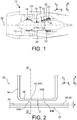
figure 3 est une vue schématique partielle en coupe transversale de l'ensemble de lafigure 2 ; - la
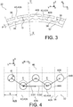
figure 4 est une vue schématique partielle développée en plan du carter de l'ensemble de lafigure 2 , illustrant la projection orthogonale d'orifices du conduit annulaire de l'ensemble, destinés à l'injection de l'air de refroidissement sur le carter.
- the
figure 1 is a schematic view in axial section of a turbomachine for an aircraft according to a preferred embodiment of the invention; - the
figure 2 is a partial schematic half-view in axial section of an assembly comprising a casing of a turbine of the turbomachine of thefigure 1 as well as an annular duct surrounding this casing for injecting cooling air into the casing; - the
figure 3 is a partial schematic view in cross section of the assembly of thefigure 2 ; - the
figure 4 is a partial schematic plan view of the housing of the assembly of thefigure 2 , illustrating the orthogonal projection of orifices of the annular duct of the assembly, intended for the injection of cooling air into the casing.
La
Dans la description qui suit, les directions X, Y et Z constituent respectivement les directions longitudinale, transversale, et verticale, de la turbomachine. La direction longitudinale X est également dénommée « direction axiale ». Les directions radiale R et circonférentielle C sont définies par rapport à l'axe longitudinal 28.In the following description, the directions X, Y and Z respectively constitute the longitudinal, transverse and vertical directions of the turbomachine. The longitudinal direction X is also called “axial direction”. The radial R and circumferential C directions are defined with respect to the
D'une manière connue en soi, la turbine basse pression 22 comporte un rotor 30 comprenant une pluralité de disques montés à rotation autour de l'axe longitudinal 28 et pourvus d'aubes mobiles s'étendant dans le passage du flux primaire issu de la chambre de combustion 18. La turbine basse pression 22 comporte en outre des rangées annulaires d'aubes statiques disposées en alternance avec les disques du rotor 30. Enfin, la turbine basse pression 22 comporte un carter 32 qui entoure le rotor 30, et des moyens 33 de pilotage des jeux radiaux au sommet des aubes mobiles. Ces moyens de pilotage des jeux radiaux 33 comprennent typiquement un ou plusieurs conduits annulaires 34 (
Chaque conduit annulaire 34 comprend une paroi annulaire radialement interne 36 s'étendant en regard d'une surface externe 38 du carter 32 et pourvue d'orifices 40 destinés à injecter l'air de refroidissement en direction du carter 32 selon une incidence sensiblement normale de manière à refroidir le carter 32 par impact.Each
Selon une particularité de l'invention, comme le montrent les
Comme le montre plus particulièrement la
Plus généralement, dans le cas où le nombre de rangées annulaires d'orifices est supérieur à deux, tout couple de rangées annulaires consécutives est tel que les orifices 40 de l'une des rangées annulaires du couple sont centrés par rapport aux premières rainures 42A tandis que les orifices 40 de l'autre rangée annulaire du couple sont centrés par rapport aux secondes rainures 42B.More generally, in the case where the number of annular rows of orifices is greater than two, any pair of consecutive annular rows is such that the orifices 40 of one of the annular rows of the pair are centered relative to the
Ainsi, chaque orifice 40 de l'une des rangées annulaires est décalé circonférentiellement par rapport aux deux orifices consécutifs d'une rangée annulaire voisine situés au plus près de l'orifice considéré.Thus, each orifice 40 of one of the annular rows is circumferentially offset with respect to the two consecutive orifices of a neighboring annular row located as close as possible to the orifice in question.
Le nombre d'orifices 40 pouvant être agencés sur une superficie donnée est ainsi accru par rapport à celui des conduits annulaires conventionnels, tout en permettant de respecter la valeur minimale d'entraxe E imposée, par exemple égale à 1,6 mm dans le mode de réalisation de l'invention illustré.The number of orifices 40 that can be arranged over a given area is thus increased compared to that of conventional annular ducts, while making it possible to comply with the minimum value of center distance E imposed, for example equal to 1.6 mm in the mode. embodiment of the invention illustrated.
Plus spécifiquement, chaque orifice 40A, 40B débouche ainsi en regard d'une rainure axiale 42A, 42B différente des rainures axiales 42B, 42A dans lesquelles débouchent les orifices voisins 40B, 40A qui appartiennent à une autre rangée annulaire que celle de l'orifice considéré.More specifically, each
Les inventeurs ont démontré que les rainures axiales 42 permettent de canaliser les jets d'air de refroidissement issus des orifices 40 et d'éviter que ces jets n'interfèrent entre eux d'une manière nuisible au refroidissement du carter 32.The inventors have demonstrated that the
Dans certaines variantes de réalisation de l'invention, chaque rainure axiale 42 s'étend ainsi continument en regard de plusieurs des orifices 40 qui appartiennent respectivement à plusieurs rangées annulaires 44A ou 44B non consécutives.In certain variant embodiments of the invention, each
Il est à noter que le carter 32 et le ou les conduits annulaires 34 forment un ensemble pour turbine dans la terminologie adoptée dans la présente description.It should be noted that the
Dans l'exemple illustré, toutes les rainures axiales présentent la même forme, et en particulier la même largeur L selon la direction circonférentielle.In the example illustrated, all the axial grooves have the same shape, and in particular the same width L in the circumferential direction.
De plus, chaque première rainure 42A est contigüe aux deux secondes rainures 42B qui lui sont consécutives. Bien évidemment, cela implique que chaque seconde rainure 42B est contigüe aux deux premières rainures 42A qui lui sont consécutives.In addition, each
Par conséquent, chaque orifice 40A, 40B de l'une des rangées annulaires 42A, 42B est situé à une distance circonférentielle CD1 égale à la moitié de la distance circonférentielle CD2 qui sépare deux orifices consécutifs 40B, 40A d'une rangée annulaire voisine 42B, 42A situés au plus près de l'orifice 40 considéré.Consequently, each
Dans l'exemple illustré, la distance D entre le fond 46 de chacune des rainures axiales et la paroi annulaire radialement interne 36 du conduit annulaire est comprise entre trois fois et cinq fois la profondeur P de chacune des rainures axiales 42.In the example illustrated, the distance D between the bottom 46 of each of the axial grooves and the radially internal
Dans cet exemple, la distance D est égale à 3 mm environ tandis que la profondeur P est égale à 0,8 mm environ.In this example, the distance D is equal to approximately 3 mm while the depth P is equal to approximately 0.8 mm.
De plus, la profondeur P de chacune des rainures axiales 42 est sensiblement égale au diamètre Ø des orifices 40.In addition, the depth P of each of the
Enfin, l'étendue axiale des rainures axiales 42 est déterminée en fonction de la configuration du carter 32 et du ou des conduits annulaires 34, et est de préférence supérieure à 2,5 cm dans le mode de réalisation de l'invention illustré.Finally, the axial extent of the
Il est à noter que le principe de l'invention, décrit ci-dessus dans le cas d'une turbine basse pression d'un turboréacteur, peut être appliqué de manière analogue à une turbine haute pression d'un turboréacteur ou encore à une turbine d'un turbopropulseur, ou d'une turbomachine à doublet d'hélices non carénées, également dénommée « open rotor », ou plus généralement à tout type de turbine dans tout type de turbomachine.It should be noted that the principle of the invention, described above in the case of a low pressure turbine of a turbojet, can be applied in a similar manner to a high pressure turbine of a turbojet or even to a turbine. of a turboprop engine, or of a turbomachine with a doublet of non-ducted propellers, also called “open rotor”, or more generally of any type of turbine in any type of turbomachine.
Claims (7)
- Assembly for a turbine (22) of a turbine engine (10), comprising a casing (32) and at least one annular duct (34) surrounding the casing, the annular duct being capable of being connected to means for supplying cooling air (35), and having a radially inner annular wall (36) provided with openings (40) arranged opposite an outer surface (38) of the casing in order to cool said casing by the impact of cooling-air jets, characterised in that the casing has a plurality of axial grooves (42) comprising first grooves (42A) and second grooves (42B) arranged in alternation such that each first groove (42a) is contiguous to the two second grooves (42B) consecutive thereto, and in that the openings are distributed in a plurality of annular rows (44A, 44B) in which any pair of consecutive annular rows (44A, 44B) is such that the openings (40A) of one (44A) of the annular rows of the pair are centred relative to the first grooves (42A), while the openings (40B) of the other annular row (44B) of the pair are centred relative to the second grooves (42B).
- Assembly according to claim 1, wherein all axial grooves (42, 42A, 42B) have the same shape.
- Assembly according to any of claims 1 to 2, wherein each of the axial grooves (42) extends continuously opposite a plurality of openings (40) respectively belonging to a plurality of non-consecutive annular rows (44A, 44B).
- Assembly according to any of claims 1 to 3, wherein the distance (D) between the bottom (46) of each of the axial grooves and the radially inner annular wall (36) of the annular duct (34) lies in the range of three to five times the depth (P) of each of the axial grooves (42).
- Assembly according to any of claims 1 to 4, wherein the depth (P) of each of the axial grooves is substantially equal to the diameter (Ø) of the openings.
- Turbine (22) for a turbine engine (10), comprising a rotor (30), in addition to an assembly (32, 34) according to any of claims 1 to 5, the casing (32) of which surrounds the rotor (30) of the turbine.
- Turbine engine (10) for an aircraft, comprising at least one turbine (22) according to claim 6, in addition to means for supplying cooling air (35) connected to said annular duct (34).
Applications Claiming Priority (2)
| Application Number | Priority Date | Filing Date | Title |
|---|---|---|---|
| FR1556382A FR3038655B1 (en) | 2015-07-06 | 2015-07-06 | ASSEMBLY COMPRISING A GROOVE CASING AND MEANS FOR COOLING THE CARTER, TURBINE COMPRISING SAID ASSEMBLY, AND TURBOMACHINE COMPRISING SAID TURBINE |
| PCT/FR2016/051700 WO2017006045A1 (en) | 2015-07-06 | 2016-07-05 | Assembly for turbine |
Publications (2)
| Publication Number | Publication Date |
|---|---|
| EP3320186A1 EP3320186A1 (en) | 2018-05-16 |
| EP3320186B1 true EP3320186B1 (en) | 2021-08-25 |
Family
ID=53776889
Family Applications (1)
| Application Number | Title | Priority Date | Filing Date |
|---|---|---|---|
| EP16742374.8A Active EP3320186B1 (en) | 2015-07-06 | 2016-07-05 | Assembly of a gas turbine |
Country Status (5)
| Country | Link |
|---|---|
| US (1) | US11686215B2 (en) |
| EP (1) | EP3320186B1 (en) |
| CN (1) | CN107709709B (en) |
| FR (1) | FR3038655B1 (en) |
| WO (1) | WO2017006045A1 (en) |
Families Citing this family (1)
| Publication number | Priority date | Publication date | Assignee | Title |
|---|---|---|---|---|
| FR3100286B1 (en) * | 2019-08-30 | 2021-09-17 | Safran Aircraft Engines | TORQUE CONVERGENT-DIVERGENT FLAP FOR VARIABLE GEOMETRY TURBOREACTOR NOZZLE INCLUDING COOLING AIR CIRCULATION DUCTS CONNECTED THROUGH CONTACT SURFACES |
Citations (2)
| Publication number | Priority date | Publication date | Assignee | Title |
|---|---|---|---|---|
| EP0905353A1 (en) * | 1997-09-30 | 1999-03-31 | Abb Research Ltd. | Impingement cooled wall element |
| EP2551467A1 (en) * | 2011-07-26 | 2013-01-30 | United Technologies Corporation | Gas turbine engine active clearance control system and corresponding method |
Family Cites Families (8)
| Publication number | Priority date | Publication date | Assignee | Title |
|---|---|---|---|---|
| BE791579A (en) * | 1971-11-18 | 1973-03-16 | Penny Robert N | ENGINE CASE |
| GB1504129A (en) * | 1974-06-29 | 1978-03-15 | Rolls Royce | Matching differential thermal expansions of components in heat engines |
| FR2931872B1 (en) | 2008-05-28 | 2010-08-20 | Snecma | HIGH PRESSURE TURBINE OF A TURBOMACHINE WITH IMPROVED MOUNTING OF THE PILOTAGE HOUSING OF THE MOBILE RADIAL GAMES. |
| EP2159384A1 (en) * | 2008-08-27 | 2010-03-03 | Siemens Aktiengesellschaft | Stator vane support for a gas turbine |
| US8684662B2 (en) * | 2010-09-03 | 2014-04-01 | Siemens Energy, Inc. | Ring segment with impingement and convective cooling |
| JP2013100765A (en) | 2011-11-08 | 2013-05-23 | Ihi Corp | Impingement cooling mechanism, turbine blade, and combustor |
| US9316111B2 (en) * | 2011-12-15 | 2016-04-19 | Pratt & Whitney Canada Corp. | Active turbine tip clearance control system |
| EP2679776A1 (en) * | 2012-06-28 | 2014-01-01 | Alstom Technology Ltd | Cooling system and method for an axial flow turbine |
-
2015
- 2015-07-06 FR FR1556382A patent/FR3038655B1/en active Active
-
2016
- 2016-07-05 CN CN201680039190.5A patent/CN107709709B/en active Active
- 2016-07-05 WO PCT/FR2016/051700 patent/WO2017006045A1/en active Application Filing
- 2016-07-05 EP EP16742374.8A patent/EP3320186B1/en active Active
- 2016-07-05 US US15/741,545 patent/US11686215B2/en active Active
Patent Citations (2)
| Publication number | Priority date | Publication date | Assignee | Title |
|---|---|---|---|---|
| EP0905353A1 (en) * | 1997-09-30 | 1999-03-31 | Abb Research Ltd. | Impingement cooled wall element |
| EP2551467A1 (en) * | 2011-07-26 | 2013-01-30 | United Technologies Corporation | Gas turbine engine active clearance control system and corresponding method |
Also Published As
| Publication number | Publication date |
|---|---|
| CN107709709B (en) | 2020-11-10 |
| FR3038655B1 (en) | 2017-08-25 |
| FR3038655A1 (en) | 2017-01-13 |
| US20180195411A1 (en) | 2018-07-12 |
| WO2017006045A1 (en) | 2017-01-12 |
| US11686215B2 (en) | 2023-06-27 |
| CN107709709A (en) | 2018-02-16 |
| EP3320186A1 (en) | 2018-05-16 |
Similar Documents
| Publication | Publication Date | Title |
|---|---|---|
| EP2473713B1 (en) | Device for supporting a turbine ring, turbine having such a device, and turbine engine having such a turbine | |
| EP0176447B1 (en) | Apparatus for the automatic control of the play of a labyrinth seal of a turbo machine | |
| EP3130765B1 (en) | De-icing splitter for an axial turbine engine compressor | |
| FR3019584A1 (en) | SYSTEM FOR VENTILATION OF A TURBINE USING CROSSING ORIFICES AND LUNULES | |
| EP3069057B1 (en) | Sealing system with two rows of complementary sealing elements | |
| FR3016956A1 (en) | HEAT EXCHANGER OF A TURBOMACHINE | |
| FR3039589A1 (en) | STAGE OF TURBOMACHINE, ESPECIALLY LOW-PRESSURE TURBINE | |
| FR2973433A1 (en) | Turbine rotor for low pressure turbomachine e.g. turbojet of aircraft, has upstream and downstream disks arranged coaxially, and bearing unit supporting end portion of flange to prevent deviation of flange of downstream disk | |
| FR2978793A1 (en) | Turbine rotor for e.g. turbojet engine of aircraft, has annular ring deformed or moved in order to compensate deformation/displacement of plate so as to ensure sealing of annular space irrespective of position of plate | |
| EP3320186B1 (en) | Assembly of a gas turbine | |
| EP3673154A1 (en) | Discharge duct of an intermediate housing hub for an aircraft turbojet engine comprising cooling channels | |
| EP3824221B1 (en) | Assembly for a turbomachine | |
| FR3092612A1 (en) | Axial turbine blade retaining ring cooling system for aircraft turbomachines | |
| WO2020099762A1 (en) | Sealing between a rotor disc and a stator of a turbomachine | |
| FR3066533A1 (en) | SEALING ASSEMBLY FOR A TURBOMACHINE | |
| FR2997128A1 (en) | Guide vane e.g. fixed guide vane for e.g. turbojet engine, of aircraft, has annular hook engaged on cylindrical edge of internal wall, and annular rib co-operating with support face of wall to prevent hook from being disengaged from wall | |
| FR2999249A1 (en) | High pressure axial compressor for e.g. turbojet for aircraft, has air draining unit for injecting cooling air between rotating element and static element such that cooling air immerses side of annular sealing ribs | |
| EP3420198A1 (en) | Rectifier for aircraft turbomachine compressor, comprising air extraction openings having a stretched form in the peripheral direction | |
| EP1739309B1 (en) | Multi stage turbomachine compressor | |
| FR3103221A1 (en) | SURFACIC AIR-OIL HEAT EXCHANGER FOR DOUBLE-FLOW TURBOMACHINE INCLUDING FINS WITH A TAKING EDGE OFFSET DOWNSTREAM IN AN AXIAL DIRECTION OF AIR FLOW | |
| FR3069276B1 (en) | SEALING ASSEMBLY FOR TURBOMACHINE | |
| EP4010565B1 (en) | Seal ring for a turbine of a turbomachine or a turboengine | |
| FR3036753A1 (en) | ANNULAR BEARING BEARING CAGE FOR A TURBOMACHINE | |
| FR3107924A1 (en) | Movable ring for a turbomachine turbine, comprising an axial support end provided with differential cooling grooves | |
| FR3085405A1 (en) | PRESSURIZATION OF THE INTER-LECHETTES CAVITY BY BYPASSING THE BYPASS FLOW |
Legal Events
| Date | Code | Title | Description |
|---|---|---|---|
| STAA | Information on the status of an ep patent application or granted ep patent |
Free format text: STATUS: THE INTERNATIONAL PUBLICATION HAS BEEN MADE |
|
| PUAI | Public reference made under article 153(3) epc to a published international application that has entered the european phase |
Free format text: ORIGINAL CODE: 0009012 |
|
| STAA | Information on the status of an ep patent application or granted ep patent |
Free format text: STATUS: REQUEST FOR EXAMINATION WAS MADE |
|
| 17P | Request for examination filed |
Effective date: 20180108 |
|
| AK | Designated contracting states |
Kind code of ref document: A1 Designated state(s): AL AT BE BG CH CY CZ DE DK EE ES FI FR GB GR HR HU IE IS IT LI LT LU LV MC MK MT NL NO PL PT RO RS SE SI SK SM TR |
|
| AX | Request for extension of the european patent |
Extension state: BA ME |
|
| DAV | Request for validation of the european patent (deleted) | ||
| DAX | Request for extension of the european patent (deleted) | ||
| STAA | Information on the status of an ep patent application or granted ep patent |
Free format text: STATUS: EXAMINATION IS IN PROGRESS |
|
| 17Q | First examination report despatched |
Effective date: 20201014 |
|
| GRAP | Despatch of communication of intention to grant a patent |
Free format text: ORIGINAL CODE: EPIDOSNIGR1 |
|
| STAA | Information on the status of an ep patent application or granted ep patent |
Free format text: STATUS: GRANT OF PATENT IS INTENDED |
|
| INTG | Intention to grant announced |
Effective date: 20210129 |
|
| GRAS | Grant fee paid |
Free format text: ORIGINAL CODE: EPIDOSNIGR3 |
|
| GRAA | (expected) grant |
Free format text: ORIGINAL CODE: 0009210 |
|
| STAA | Information on the status of an ep patent application or granted ep patent |
Free format text: STATUS: THE PATENT HAS BEEN GRANTED |
|
| AK | Designated contracting states |
Kind code of ref document: B1 Designated state(s): AL AT BE BG CH CY CZ DE DK EE ES FI FR GB GR HR HU IE IS IT LI LT LU LV MC MK MT NL NO PL PT RO RS SE SI SK SM TR |
|
| REG | Reference to a national code |
Ref country code: CH Ref legal event code: EP |
|
| REG | Reference to a national code |
Ref country code: DE Ref legal event code: R096 Ref document number: 602016062726 Country of ref document: DE |
|
| REG | Reference to a national code |
Ref country code: IE Ref legal event code: FG4D Free format text: LANGUAGE OF EP DOCUMENT: FRENCH Ref country code: AT Ref legal event code: REF Ref document number: 1423999 Country of ref document: AT Kind code of ref document: T Effective date: 20210915 |
|
| REG | Reference to a national code |
Ref country code: SE Ref legal event code: TRGR |
|
| REG | Reference to a national code |
Ref country code: LT Ref legal event code: MG9D |
|
| REG | Reference to a national code |
Ref country code: NL Ref legal event code: MP Effective date: 20210825 |
|
| REG | Reference to a national code |
Ref country code: AT Ref legal event code: MK05 Ref document number: 1423999 Country of ref document: AT Kind code of ref document: T Effective date: 20210825 |
|
| PG25 | Lapsed in a contracting state [announced via postgrant information from national office to epo] |
Ref country code: RS Free format text: LAPSE BECAUSE OF FAILURE TO SUBMIT A TRANSLATION OF THE DESCRIPTION OR TO PAY THE FEE WITHIN THE PRESCRIBED TIME-LIMIT Effective date: 20210825 Ref country code: AT Free format text: LAPSE BECAUSE OF FAILURE TO SUBMIT A TRANSLATION OF THE DESCRIPTION OR TO PAY THE FEE WITHIN THE PRESCRIBED TIME-LIMIT Effective date: 20210825 Ref country code: BG Free format text: LAPSE BECAUSE OF FAILURE TO SUBMIT A TRANSLATION OF THE DESCRIPTION OR TO PAY THE FEE WITHIN THE PRESCRIBED TIME-LIMIT Effective date: 20211125 Ref country code: LT Free format text: LAPSE BECAUSE OF FAILURE TO SUBMIT A TRANSLATION OF THE DESCRIPTION OR TO PAY THE FEE WITHIN THE PRESCRIBED TIME-LIMIT Effective date: 20210825 Ref country code: PT Free format text: LAPSE BECAUSE OF FAILURE TO SUBMIT A TRANSLATION OF THE DESCRIPTION OR TO PAY THE FEE WITHIN THE PRESCRIBED TIME-LIMIT Effective date: 20211227 Ref country code: NO Free format text: LAPSE BECAUSE OF FAILURE TO SUBMIT A TRANSLATION OF THE DESCRIPTION OR TO PAY THE FEE WITHIN THE PRESCRIBED TIME-LIMIT Effective date: 20211125 Ref country code: HR Free format text: LAPSE BECAUSE OF FAILURE TO SUBMIT A TRANSLATION OF THE DESCRIPTION OR TO PAY THE FEE WITHIN THE PRESCRIBED TIME-LIMIT Effective date: 20210825 Ref country code: FI Free format text: LAPSE BECAUSE OF FAILURE TO SUBMIT A TRANSLATION OF THE DESCRIPTION OR TO PAY THE FEE WITHIN THE PRESCRIBED TIME-LIMIT Effective date: 20210825 Ref country code: ES Free format text: LAPSE BECAUSE OF FAILURE TO SUBMIT A TRANSLATION OF THE DESCRIPTION OR TO PAY THE FEE WITHIN THE PRESCRIBED TIME-LIMIT Effective date: 20210825 |
|
| PG25 | Lapsed in a contracting state [announced via postgrant information from national office to epo] |
Ref country code: PL Free format text: LAPSE BECAUSE OF FAILURE TO SUBMIT A TRANSLATION OF THE DESCRIPTION OR TO PAY THE FEE WITHIN THE PRESCRIBED TIME-LIMIT Effective date: 20210825 Ref country code: LV Free format text: LAPSE BECAUSE OF FAILURE TO SUBMIT A TRANSLATION OF THE DESCRIPTION OR TO PAY THE FEE WITHIN THE PRESCRIBED TIME-LIMIT Effective date: 20210825 Ref country code: GR Free format text: LAPSE BECAUSE OF FAILURE TO SUBMIT A TRANSLATION OF THE DESCRIPTION OR TO PAY THE FEE WITHIN THE PRESCRIBED TIME-LIMIT Effective date: 20211126 |
|
| PG25 | Lapsed in a contracting state [announced via postgrant information from national office to epo] |
Ref country code: NL Free format text: LAPSE BECAUSE OF FAILURE TO SUBMIT A TRANSLATION OF THE DESCRIPTION OR TO PAY THE FEE WITHIN THE PRESCRIBED TIME-LIMIT Effective date: 20210825 |
|
| PG25 | Lapsed in a contracting state [announced via postgrant information from national office to epo] |
Ref country code: DK Free format text: LAPSE BECAUSE OF FAILURE TO SUBMIT A TRANSLATION OF THE DESCRIPTION OR TO PAY THE FEE WITHIN THE PRESCRIBED TIME-LIMIT Effective date: 20210825 |
|
| REG | Reference to a national code |
Ref country code: DE Ref legal event code: R097 Ref document number: 602016062726 Country of ref document: DE |
|
| PG25 | Lapsed in a contracting state [announced via postgrant information from national office to epo] |
Ref country code: SM Free format text: LAPSE BECAUSE OF FAILURE TO SUBMIT A TRANSLATION OF THE DESCRIPTION OR TO PAY THE FEE WITHIN THE PRESCRIBED TIME-LIMIT Effective date: 20210825 Ref country code: SK Free format text: LAPSE BECAUSE OF FAILURE TO SUBMIT A TRANSLATION OF THE DESCRIPTION OR TO PAY THE FEE WITHIN THE PRESCRIBED TIME-LIMIT Effective date: 20210825 Ref country code: RO Free format text: LAPSE BECAUSE OF FAILURE TO SUBMIT A TRANSLATION OF THE DESCRIPTION OR TO PAY THE FEE WITHIN THE PRESCRIBED TIME-LIMIT Effective date: 20210825 Ref country code: EE Free format text: LAPSE BECAUSE OF FAILURE TO SUBMIT A TRANSLATION OF THE DESCRIPTION OR TO PAY THE FEE WITHIN THE PRESCRIBED TIME-LIMIT Effective date: 20210825 Ref country code: CZ Free format text: LAPSE BECAUSE OF FAILURE TO SUBMIT A TRANSLATION OF THE DESCRIPTION OR TO PAY THE FEE WITHIN THE PRESCRIBED TIME-LIMIT Effective date: 20210825 Ref country code: AL Free format text: LAPSE BECAUSE OF FAILURE TO SUBMIT A TRANSLATION OF THE DESCRIPTION OR TO PAY THE FEE WITHIN THE PRESCRIBED TIME-LIMIT Effective date: 20210825 |
|
| PLBE | No opposition filed within time limit |
Free format text: ORIGINAL CODE: 0009261 |
|
| STAA | Information on the status of an ep patent application or granted ep patent |
Free format text: STATUS: NO OPPOSITION FILED WITHIN TIME LIMIT |
|
| 26N | No opposition filed |
Effective date: 20220527 |
|
| PG25 | Lapsed in a contracting state [announced via postgrant information from national office to epo] |
Ref country code: SI Free format text: LAPSE BECAUSE OF FAILURE TO SUBMIT A TRANSLATION OF THE DESCRIPTION OR TO PAY THE FEE WITHIN THE PRESCRIBED TIME-LIMIT Effective date: 20210825 |
|
| PG25 | Lapsed in a contracting state [announced via postgrant information from national office to epo] |
Ref country code: MC Free format text: LAPSE BECAUSE OF FAILURE TO SUBMIT A TRANSLATION OF THE DESCRIPTION OR TO PAY THE FEE WITHIN THE PRESCRIBED TIME-LIMIT Effective date: 20210825 |
|
| REG | Reference to a national code |
Ref country code: CH Ref legal event code: PL |
|
| REG | Reference to a national code |
Ref country code: BE Ref legal event code: MM Effective date: 20220731 |
|
| PG25 | Lapsed in a contracting state [announced via postgrant information from national office to epo] |
Ref country code: LU Free format text: LAPSE BECAUSE OF NON-PAYMENT OF DUE FEES Effective date: 20220705 Ref country code: LI Free format text: LAPSE BECAUSE OF NON-PAYMENT OF DUE FEES Effective date: 20220731 Ref country code: CH Free format text: LAPSE BECAUSE OF NON-PAYMENT OF DUE FEES Effective date: 20220731 |
|
| PG25 | Lapsed in a contracting state [announced via postgrant information from national office to epo] |
Ref country code: BE Free format text: LAPSE BECAUSE OF NON-PAYMENT OF DUE FEES Effective date: 20220731 |
|
| PG25 | Lapsed in a contracting state [announced via postgrant information from national office to epo] |
Ref country code: IE Free format text: LAPSE BECAUSE OF NON-PAYMENT OF DUE FEES Effective date: 20220705 |
|
| PGFP | Annual fee paid to national office [announced via postgrant information from national office to epo] |
Ref country code: IT Payment date: 20230620 Year of fee payment: 8 Ref country code: FR Payment date: 20230621 Year of fee payment: 8 |
|
| PGFP | Annual fee paid to national office [announced via postgrant information from national office to epo] |
Ref country code: SE Payment date: 20230622 Year of fee payment: 8 |
|
| PGFP | Annual fee paid to national office [announced via postgrant information from national office to epo] |
Ref country code: GB Payment date: 20230620 Year of fee payment: 8 |
|
| PGFP | Annual fee paid to national office [announced via postgrant information from national office to epo] |
Ref country code: DE Payment date: 20230620 Year of fee payment: 8 |
|
| PG25 | Lapsed in a contracting state [announced via postgrant information from national office to epo] |
Ref country code: HU Free format text: LAPSE BECAUSE OF FAILURE TO SUBMIT A TRANSLATION OF THE DESCRIPTION OR TO PAY THE FEE WITHIN THE PRESCRIBED TIME-LIMIT; INVALID AB INITIO Effective date: 20160705 |