EP3809639A1 - Dispositif de traitement de réseau et procédé de traitement de réseaux de trames de communication - Google Patents
Dispositif de traitement de réseau et procédé de traitement de réseaux de trames de communication Download PDFInfo
- Publication number
- EP3809639A1 EP3809639A1 EP20200478.4A EP20200478A EP3809639A1 EP 3809639 A1 EP3809639 A1 EP 3809639A1 EP 20200478 A EP20200478 A EP 20200478A EP 3809639 A1 EP3809639 A1 EP 3809639A1
- Authority
- EP
- European Patent Office
- Prior art keywords
- rule
- address
- frame
- processing
- collision
- Prior art date
- Legal status (The legal status is an assumption and is not a legal conclusion. Google has not performed a legal analysis and makes no representation as to the accuracy of the status listed.)
- Pending
Links
Images


Classifications
-
- H—ELECTRICITY
- H04—ELECTRIC COMMUNICATION TECHNIQUE
- H04L—TRANSMISSION OF DIGITAL INFORMATION, e.g. TELEGRAPHIC COMMUNICATION
- H04L12/00—Data switching networks
- H04L12/28—Data switching networks characterised by path configuration, e.g. LAN [Local Area Networks] or WAN [Wide Area Networks]
- H04L12/40—Bus networks
- H04L12/40052—High-speed IEEE 1394 serial bus
- H04L12/40071—Packet processing; Packet format
-
- H—ELECTRICITY
- H04—ELECTRIC COMMUNICATION TECHNIQUE
- H04L—TRANSMISSION OF DIGITAL INFORMATION, e.g. TELEGRAPHIC COMMUNICATION
- H04L45/00—Routing or path finding of packets in data switching networks
- H04L45/74—Address processing for routing
- H04L45/745—Address table lookup; Address filtering
- H04L45/7453—Address table lookup; Address filtering using hashing
-
- G—PHYSICS
- G06—COMPUTING; CALCULATING OR COUNTING
- G06F—ELECTRIC DIGITAL DATA PROCESSING
- G06F13/00—Interconnection of, or transfer of information or other signals between, memories, input/output devices or central processing units
- G06F13/14—Handling requests for interconnection or transfer
- G06F13/16—Handling requests for interconnection or transfer for access to memory bus
- G06F13/1605—Handling requests for interconnection or transfer for access to memory bus based on arbitration
- G06F13/161—Handling requests for interconnection or transfer for access to memory bus based on arbitration with latency improvement
- G06F13/1626—Handling requests for interconnection or transfer for access to memory bus based on arbitration with latency improvement by reordering requests
- G06F13/1631—Handling requests for interconnection or transfer for access to memory bus based on arbitration with latency improvement by reordering requests through address comparison
-
- H—ELECTRICITY
- H04—ELECTRIC COMMUNICATION TECHNIQUE
- H04L—TRANSMISSION OF DIGITAL INFORMATION, e.g. TELEGRAPHIC COMMUNICATION
- H04L45/00—Routing or path finding of packets in data switching networks
- H04L45/54—Organization of routing tables
-
- H—ELECTRICITY
- H04—ELECTRIC COMMUNICATION TECHNIQUE
- H04L—TRANSMISSION OF DIGITAL INFORMATION, e.g. TELEGRAPHIC COMMUNICATION
- H04L49/00—Packet switching elements
- H04L49/30—Peripheral units, e.g. input or output ports
- H04L49/3009—Header conversion, routing tables or routing tags
-
- H—ELECTRICITY
- H04—ELECTRIC COMMUNICATION TECHNIQUE
- H04L—TRANSMISSION OF DIGITAL INFORMATION, e.g. TELEGRAPHIC COMMUNICATION
- H04L49/00—Packet switching elements
- H04L49/90—Buffering arrangements
- H04L49/901—Buffering arrangements using storage descriptor, e.g. read or write pointers
-
- H—ELECTRICITY
- H04—ELECTRIC COMMUNICATION TECHNIQUE
- H04L—TRANSMISSION OF DIGITAL INFORMATION, e.g. TELEGRAPHIC COMMUNICATION
- H04L69/00—Network arrangements, protocols or services independent of the application payload and not provided for in the other groups of this subclass
- H04L69/22—Parsing or analysis of headers
-
- H—ELECTRICITY
- H04—ELECTRIC COMMUNICATION TECHNIQUE
- H04L—TRANSMISSION OF DIGITAL INFORMATION, e.g. TELEGRAPHIC COMMUNICATION
- H04L12/00—Data switching networks
- H04L12/28—Data switching networks characterised by path configuration, e.g. LAN [Local Area Networks] or WAN [Wide Area Networks]
- H04L12/40—Bus networks
- H04L2012/40267—Bus for use in transportation systems
- H04L2012/40273—Bus for use in transportation systems the transportation system being a vehicle
-
- H—ELECTRICITY
- H04—ELECTRIC COMMUNICATION TECHNIQUE
- H04L—TRANSMISSION OF DIGITAL INFORMATION, e.g. TELEGRAPHIC COMMUNICATION
- H04L2101/00—Indexing scheme associated with group H04L61/00
- H04L2101/60—Types of network addresses
- H04L2101/618—Details of network addresses
- H04L2101/622—Layer-2 addresses, e.g. medium access control [MAC] addresses
Definitions
- the present invention relates to a network processing apparatus and a method of processing a network communication frame, for example, a network processing apparatus mounted on a vehicle, a method of processing a network communication frame, and a semiconductor device constituting them.
- a vehicle such as an automobile
- a number of sensors for monitoring the status of the vehicle and a human interface or the like for notifying the driver of the state of the vehicle is mounted.
- Such sensors and human interfaces are connected to Ethernet buses, for example, to form communication systems.
- Ethernet-TSN Time-Sensitive Networking
- Ethernet-TSN standard has been developed in IEEE standard since 2017, and has attracted attention as a core technique for advanced driving support systems (ADAS) and automated driving.
- ADAS advanced driving support systems
- Ethernet-TSN standard is not limited to an in-vehicle communication system and can be applied to various systems, in the present specification, Ethernet-TSN standard is exemplified as being applied to an in-vehicle communication system.
- the rule in the method of processing the network processing apparatus or the network communication frame, defines a rule for processing the received frame, the rule is input to the hash generator, the resulting hash value Obtain an address based on, the position of the address in the rule table, stores the rule.
- the rule is input to the hash generator, in addition to the configuration for obtaining an address based on the resulting hash value, a configuration for detecting the presence or absence of a collision of the hash value, and a configuration for generating an address when a collision of the hash value occurs.
- FIG. 1 is a diagram showing a configuration of an automobile in which a communication system according to a first embodiment is mounted. 1, the automobile 200, the communication system 1 is mounted.
- the communication system 1 includes a device equipped with an automobile, a switch control circuit corresponding to the device, and an ethernet bus connected to the device through a switch control circuit.
- various sensors, various human interfaces and ECUs (Engine control circuit) are shown as devices mounted on an automobile.
- sensors include cameras, radars, Lidar and sonars. These sensors are connected to the gateway 5 via the switch control circuit 2.
- Examples of the human interface include a navigation device, a meter (instrument), a rear monitor, and a cockpit. These human interfaces are connected to the gateway 5 via the switch control circuit 3. Further, a plurality of ECUs are connected to the gateway 5 through the switch control circuit 4.
- Switch control circuits 2, 3 and 4 a port PB connected to the gateway 5, and a port PI connected to the device, and a TSN control circuit, as shown in the figure, to connect the gateway 5 to the port PB, by connecting the device to the port PI, communication between the device and the gateway 5 via the switch control circuits 2, 3 and 4 It becomes possible. This allows communication between the devices through the gateway 5.
- the gateway 5 can also communicate with the outside of the automobile 200 by being connected to a global network configured outside the automobile 200 via the modem 6.
- a single switch control circuit 2 monitors and controls a plurality of sensors connected to the port PI.
- the communication system 1 may be provided with a switch control circuit corresponding to each of the human interface and the ECU, and each of the human interface and the ECU may be monitored and controlled by the corresponding switch control circuit.
- the gateways 5 relay communications between the switch control circuits 2, 3, and 4 and the modems 6, thereby enabling the sensors and ECUs, which are terminal devices, to transmit and receive data using protocols based on Ethernet-TSN standard. Transmission and reception of this data, in Ethernet-TSN standard, the network communication frame comprising the communication data (hereinafter, frame) identifies the destination terminal device based on the frame header information given to, the routing to determine the transfer path It is realized by a function called.
- the gateway 5 includes a network router 5_1 as a network processing device (network processor) for routing.
- the frame header information and other elements constituting the frame may also be referred to simply as a frame.
- the network router 5_1 analyzes the frame transmitted from the source terminal device, and determines what processing to be performed on the subsequent frame. This function is called a filter. In particular, in a system connected to a global network, it is effective to use a network switch to protect the security level in internal and external networks.
- a data table 1001 is created to define a frame that allows acceptance.
- the data table stores data elements such as the offset position of the predetermined data in the frame permitting acceptance, the value of the data, the mask bit for masking the data, the width of the value, and the like.
- each data element is assumed to be A, B, C, D, E, F and G. That is, these A,B,C,D,E, F and G are intended to represent the type or configuration information of the data included in the frame, not the data itself included in the frame.
- a search condition that is, a search rule (hereinafter, referred to as a rule) RULE is created by combining the data elements of the data table 1001.
- the rule has a combination pattern similar to that of a frame, and creates a plurality of rules corresponding to variations in the data structure of the frame that permits acceptance, registers one rule corresponding to one address ADDR, and configures the rule table 1002.
- Network switch 5051 the data configuration of the received frame by comparing whether it is defined in the rule table 1002 to determine a match or mismatch, or accept the received frame as a processing target, it is possible to determine whether to discard without accepting as a processing target.
- each rule is given group information GRP indicating which of the plurality of defined groups X and Y corresponds to the process to be applied.
- a typical process required as the network router 5_1 is a process of analyzing the contents of a frame and specifying a transfer destination in order to forward a frame from one terminal connected to the gateway 5 to another terminal.
- the reception frame FRM_0 is composed of the data elements of ⁇ A, B, C, D ⁇ .
- the data elements are referred to as received frames ⁇ A, B, C, D ⁇ .
- A, B, C, and D represents the type of data included in the frame, i.e. the configuration information, not the data itself included in the frame.
- step ST_102 from the rule table 1002, it searches for a match with the data element of the received frame.
- Each rule is assigned group information indicating the reference destination of the process table 1003, the group GRP assigned in response to the received frame is selected.
- the group X is selected corresponding to the received frame FRM_0 ⁇ A, B, C, D ⁇ .
- step ST_103 refers to the process corresponding to the selected group X from the process table 1003, by the registered process is called, the process corresponding to the received frame FRM_0 ⁇ A, B, C, D ⁇ is executed.
- Typical processes performed by the network switch 5051 include, for example, the transfer of a frame FRM from one terminal connected to the gateway 5 to another terminal.
- the inventors have found the following problems. That is, in the above example, when retrieving the reception frame FRM from the rule table 1002, until the reception frame FRM is found, it is necessary to confirm all the contents of the rule table (comparison).
- the rule table is implemented in registers and memories, a large amount of comparison circuits is required to perform comparison processing at high speed, which increases the circuit area and increases the power consumption.
- the comparison circuit is reduced in order to reduce the circuit area and the comparison process is divided into multiple times, the retrieval time becomes longer.
- the network router 5_1 according to the first embodiment is configured based on the analysis of the above-described study example.
- the network router 5_1 is a network processor having a routing function, and is typically configured by a semiconductor integrated circuit (semiconductor device, semiconductor chip).
- the semiconductor device for example, a semiconductor substrate made of single crystal silicon, is constituted by a plurality of circuits formed using a known CMOS manufacturing process. Details thereof will be described below.
- the network router 5_1 includes a CPU (central processing unit) 501, a DMAC (direct memory access control circuit) 502, a G-RAM (global random access memory) 503, a Flash memory 504, a network switch 505, and a bus 506 interconnecting them.
- CPU501 executes the program code stored in G-RAM503 or Flash memory 504, transmits and receives data to and from other components via the bus 506, and issues commands.
- DMAC502 manages and controls the sending and receiving of data between the components without CPU501.
- G-RAM503 and Flash memories 504 are data and program storage areas accessible from the above components via bus 506.
- G-RAM503 is comprised of volatile memory, such as a SRAM or DRAM
- Flash memory 504 is comprised of non-volatile memory.
- Network switch 505 the main part of the routing and filter functions according to the present embodiment is implemented.
- the network switch 505 includes an external bus 507 and an external interface 508 connected to the network router 5_1 and is capable of communicating with external devices of the network router 5_1.
- the configuration of the network router 5_1 may be a form of a microcontrol circuit (MCU) or a microprocessor (MPU) adapted to the routing process.
- MCU microcontrol circuit
- MPU microprocessor
- FIG. 4 shows a configuration of a main part of the network switch 505 according to the first embodiment.
- the network switch 505 includes a data table 101, a rule table 102, a process table 103, a hash generator 104, a frame analyzer 105, a frame-to-rule comparator 106, a collision control circuit 107, a frame process control circuit 108, and a control circuit 109.
- the data table 101, the rule table 102, and the process table 103 divide the data comprising the frame into fine elements, and arrange the rows and combinations of the patterns on the matrix.
- these tables are held in an internal memory 110 such as a DRAM memory (not shown).
- internal memory 110 allows direct access only from within network switch 505 and is not directly accessible from other components connected to bus 506.
- the hash generator 104 generates hash value HASH by applying a particular algorithm/function to the received data.
- the hash value HASH is smaller data representing the accepted data and can be used as an index for retrieving the accepted data.
- Known techniques such as CRCs or SHAs can be used as algorithms or functions for generating hash value HASH. For example, it can be configured to receive data having a data width of 128 bits and output a hash value of 10 bits.
- the rule RULE and processing corresponding to the received frame FRM It shows those belonging to the defining part defining. Note that a broken line arrow in the drawing means that a certain process or operation is applied to a target to which the arrow is connected. It is to be noted that the following series of processing flows are implemented and controlled by the control circuit 109 included in the network switch 505 unless otherwise specified.
- the control circuit 109 creates a data table 101 to define rules of frames permitted to be accepted as initialization.
- the data table contains data elements such as position, value, mask bit, and width of the values for the frames to be accepted.
- each data element is assumed to be A, B, C, D, E, F and G.
- the control circuit 109 combines the data elements of the data table 101 to create a rules RULE.
- This rule RULE has a combination pattern of data elements similar to a frame, and constructs a rule table 102 by creating a rule RULE corresponding to a variation of a frame that allows acceptance, and registering (storing) one rule corresponding to one address ADDR.
- Network switch 505 the combination of the data elements of the received frame compares whether it is defined in the rule table 102, by determining a match or mismatch, or accepts the received frame as a processing target, it is possible to determine whether to discard without accepting as a processing target.
- each rule has a process group information GRP that indicates which of the group X and Y is defined in a plurality of ways corresponding to the processing to be applied.
- the MAC address in Ethernet standard can be used as the rule RULE. Further, instead of the MAC address, it may be configured to include the frame information defining the destination of the frame in the communication system 1 in the rule RULE.
- the address ADDR uses the hash value HASH obtained by entering a rule RULE into the hash generator 104.
- FIG. 5 illustrates an example in which, in the process OPD3, the rules RULE1 ⁇ A, E, F, G, D ⁇ corresponding to the received frame FRM1 are inputted to the hash generator 104, and 2 is obtained as the hash HASH1.
- the collision bit COL is a two-state signal, i.e., a bit, that stores information indicating that a rule has already been stored in the address. If the collision bit COL is True (1, true), it indicates that the rule has already been stored at the address, and if the collision bit COL is False (0, false), it indicates that the rule has not been stored at the address. In a state in which no rule is registered in the rule table in the initialization state, the collision bits COL of all addresses are False (0).
- the same value as the hash value HASH1 is used as the address ADDR in the rule table 102 in which the rule RULE1 is stored.
- the collision bit COL which indicates that the rule has already been stored in the address, is set to 1True (1).
- the collision bit COL at the address where the rule is not stored is configured to be set to False (0).
- FIG. 5A illustrates an example in which the process group "X" is specified as the process group information GRP defining the process corresponding to the rule RULE1.
- the control circuit 109 writes the processing to be executed corresponding to the process group "X" in the process table 103.
- the process table 103 is illustrated as a process executed corresponding to a certain process group, and defines a type of processing such as frame deletion, transfer destination setting, stream grouping, and the like.
- the network switch 505 can execute the process PRC defined in the process group "X" when receiving the reception frame FRM1 ⁇ A, E, F, G, D ⁇ .
- FIG. 5B is referred to.
- the control circuit 109 inputs the rules RULE2 ⁇ B, D, C, A ⁇ corresponding to the received frame FRM2 to the hash generator 104, and obtains 1 as the hash HASH2.
- the network switch 505 when receiving the reception frame FRM2 ⁇ B, D, C, A ⁇ , it is possible to execute the process PRC defined by the process group "Y".
- the control circuit 109 repeats the above-described processing, defines rules for all combinations of the frame FRMs for which inputs are received, stores the rules in the rule table 102 using the hash-value HASH corresponding to the defined rules, and stores the processing executed corresponding to the rules in the process table.
- the hash value HASH is uniquely determined for the rule RULE, an independent hash value HASH is not necessarily determined for all combinations of the rule RULE.
- 1 is obtained as the hash-value HASH3 for the rules RULE3 ⁇ A, B, C, E ⁇ corresponding to the received frame FRM3.
- the hash generator 104 outputs the same hash value for different input data is called a hash collision.
- the address ADDR 2
- the rule RULE1 corresponding to the received frame FRM1 has been stored
- the corresponding collision bit COL is a True (1).
- the collision control circuit 107 determines that the collision bit COL is False(0).
- the process group "Y" is specified as the process group information GRP that defines the process corresponding to the rule RULE3.
- the rules RULE and processing corresponding to the received frame FRMs are defined parts.
- the switching operation part that performs the process defined in the defining process according to the rules RULE will be described.
- FIGS. 6A to 6B show a flow of a processing method of a network communication frame in the network switch 505 according to the first embodiment, which belongs to a switch operation part for performing processing defined by a definition part according to a received frame FRM. It should be noted that the following series of processing flows are implemented and controlled by the control circuit 109 included in the network switch 505 unless otherwise specified.
- the control circuit 109 receives the received frame FRM from the outside of the network switch 505, in the subsequent processing OPP02, the frame analyzer 105 analyses the data constituting the received frame FRM.
- the instruction of the control circuit 109, the frame analyzer 105 analyses the received frame FRM, and outputs RULE1 ⁇ A, E, F, G, D ⁇ is exemplified.
- the control circuit 109 inputs RULE1 ⁇ A, E, F, G, D ⁇ to the hash generator 104 to obtain 2 as the hash HASH1.
- control circuit 109 in response to a determination of a match at the processing OPP06, refers to the process group information GRP affixed to the rule RULE1 to obtain the process group "X".
- the control circuit 109 reads the processing PRC defined corresponding to the process group "X" from the process table 103, and instructs the frame process control circuit 108 to execute the predetermined processing PRC.
- the frame process control circuit 108 controls each component of the network router 5_1 including the network switch 505 in response to an instruction from the frame process control circuit 108, thereby achieving execution of predetermined processing PRC.
- the control circuit 109 receives the next reception frame FRM from the outside of the network switch 505.
- the instruction of the control circuit 109, the frame analyzer 105 analyses the next received frame FRM, and outputs a rule RULE3 ⁇ A, B, C, E ⁇ corresponding to the received frame FRM3.
- the control circuit 109 inputs the rules RULE3 ⁇ A, B, C, E ⁇ to the hash generator 104 to obtain 1 as the hash HASH3.
- the frame-to-rule comparator 106 adds 1 to the address ADDR. In other words, the addressing ADDR is incremented.
- the frame-to-rule comparator 106 adds an additional 1 to the address ADDR. In other words, the addressing ADDR is incremented further.
- control circuit 109 refers to the process group information GRP attached to the rules RULE3 in response to determination of coincidence in the processing OPP21, and obtains the process group information "Y".
- the control circuit 109 reads the processing PRC defined corresponding to the process group "Y" from the process table 103, and instructs the frame process control circuit 108 to execute the predetermined processing PRC.
- the frame process control circuit 108 controls each component of the network router 5_1 including the network switch 505 in response to an instruction from the frame process control circuit 108, thereby achieving execution of predetermined processing PRC.
- FIG. 7 is a flowchart showing a method of processing a network communication frame in the network switch 505 according to the first embodiment described above, the method belonging to the definition part.
- the step SD00 is a step that indicates the beginning of the rule registration process.
- the step SD01 corresponds to the processing OPD01 in the step of creating a data table 101 to define a frame to allow acceptance.
- Step SD02 is a step of creating a rule RULE corresponding to the reception frame FRM by combining the data elements of the data table 101, corresponding to the processing OPD02.
- Step SD03 corresponds to the processing OPD03, the processing OPD08, and the processing OPD13 in the step of inputting the rule RULE to the hash generator 104 and obtaining the hash value HASH and making the address ADDR.
- Step SD04 is a step of reading the data of the position referred to by the address ADDR in the rule table 102, corresponding to the processing OPD04, processing OPD09, processing OPD14, processing OPD17, processing OPD20.
- the step SD05 corresponds to the processing SD04, the processing OPD05, OPD10 processing, OPD15 processing, OPD18 processing, and the processing SD05 in the step of determining whether or not there is already a registered rule in the data at the position referenced by the address ADDR by determining True (1) or False (0) of the collision bit COL included in the data acquired by reading the step SD04.
- the step SD06 is the step of adding (incrementing) 1 to the address ADDR, corresponding to the processing OPD16, the processing OPD19.
- the step SD07 corresponds to the processing OPD06, the processing OPD11, and the processing OPD22 in the step of writing the rule RULE and the corresponding process group information GRP at the position referenced by the address ADDR in the rule table 102.
- the step SD08 writes the processing executed in response to the process group information GRP to the process table, and corresponds to the processing OPD07, the processing OPD12, and the processing OPD23.
- the step SD09 is the step that completes the creation of the rule.
- FIG. 8 is a flowchart showing a method of processing a network communication frame in the network switch 505 according to the first embodiment described above, which belongs to a switch operation part.
- the step SP00 is the step that indicates the beginning of the routing.
- the step SP01 corresponds to the processing OPP01, OPP09 in the step in which the network switch 505 receives the received frame FRM from the outside.
- the step SP02 is a step of analyzing the received frame FRM to identify a combination of data, corresponding to the processing OPP02, the processing OPP10.
- the step SP03 corresponds to the processing OPP03 in the step of inputting the data configuration of the received frame FRM specified in the step SP02 to the hash generator 104, obtaining the hash value HASH and making the address ADDR.
- the step SP04 is the step of leading data at the point referred to in the address ADDR in the rule table 102, corresponding to processing OPP04, processing OPP11, processing OPP15, and processing OPP19.
- the step SP05 corresponds to the processing OPP05, processing OPP12, processing OPP16, and processing OPP20 in the step of determining whether or not already registered rules exist in the data of the position referred to by the address ADDR by determining True (1) or False (0) of the collision bit-COL included in the data acquired by the read of the step SP04.
- the step SP06 corresponds to the processing OPP06, processing OPP13, processing OPP17, and processing OPP21 in the step of comparing whether the already registered rule RULE in the step SP05 matches the data sequence of the received frame FRM.
- the step SP07 is the step of adding (incrementing) 1 to the address ADDR, corresponding to the processing OPP14, the processing OPP18.
- the step SP08 refers to the process group information GRP provided in the rule RULE that matches the data configuration of the received frame FRM, in the step of identifying the corresponding process group, corresponding to the process OPP07, the process OPP22.
- the step SP09 is a step that executes a process corresponding to the process group specified in the step SP08, and corresponds to the process OPP08 and the process OPP23.
- Step SP10 is a step of determining not to process the received frame FRMs in response to the determination that there are no registered rules in step SP05.
- the step SP11 is the step that completes routing.
- a main effect of the network switch 505 according to the first embodiment is as follows. That is, the storage address of the rule RULE in the rule table 102 is determined according to the hash value HASH of the rule RULE. Thus, when a desired rule RULE is retrieved from the rule table 102, the hash HASH can be retrieved as an index instead of sequentially retrieving the rule table 102 from the beginning. According to the above-described configuration and method, since the processing for reading and comparing data in the rule table 102 can be reduced, the network switch 505 can be configured with a small area and low power consumption.
- Another effect of the network switch 505 according to the first embodiment is as follows. That is, since the rule table 102 includes the collision bit COL and is configured to increment the address ADDR according to the value of the collision bit COL, even if the hash value corresponding to the rule RULE conflicts, the storage destination of the rule RULE in the rule table 102 can be allocated, and the allocated rule RULE can be appropriately retrieved.
- the definition part and the switch operation part may be separately executed, or may be executed in parallel.
- the rule RULE can be newly registered in the rule table 102 during the switching operation.
- the incrementing of address ADDR in step SD06 and step SP07 can be replaced by other methods.
- a method of using a random number instead of 1 as an increment value a method of applying an arithmetic operation with an arbitrary number, a method of allowing an arbitrary value to be specified by register setting or the like, a method of selecting from a plurality of values according to the calculated value of the hash or the occurrence state of the collision, and a method of combining them as appropriate may be mentioned as an example.
- FIG. 9 is a diagram showing a configuration example of the rule table 102a included in the network switch 505a according to the second embodiment.
- the network switch 505a may be the same as the first embodiment except for the rule tables 102a_0, 102a_1, and 102a_2 and the processing method of the internal data thereof.
- the internal configuration, processing, and operation steps of the network switch 505a are denoted by the same reference numerals as those in the first embodiment, and the description of the first embodiment is applied mutatis mutandis.
- rule table 102 also requires a data width of more than 200 bits per rule, and may require that tens of thousands, perhaps billions, or more, of rules be stored.
- the second embodiment expands the configuration of the rule table 102 in the network switch 505 according to the first embodiment and the processing method of its internal data, and discloses a configuration and method for efficiently implementing the functions of the rule table 102 with less hardware assets.
- the reception frame FRMa includes frame header HD as information associated with the frame.
- Frame header HD is information that roughly classifies the data structure of a frame. For example, among network protocols such as IPv4, ICMPv4, IGMPv3, a protocol conforming to a frame FRM can be specified by the value of the frame header HD.
- FIG. 10A illustrates an example in which the network switch 505a accepts a frame having a total data structure of 27 pieces of data FRM1a ⁇ HD, A, B, C, D,., X, Y, Z ⁇ as a received frame.
- the received frame FRM1a includes frame headers HD.
- the frame headers HD of the received frame FRM1a for which processing is to be accepted are analyzed.
- a value that can be taken by the frame header HD assumes three values 0, 1, 2 corresponding to the type of the network protocol received frame conforms.
- the process proceeds to the next OPDa02.
- the processing OPDa02 when defining the rule RULE1a corresponding to the received frame FRM1a, among the data structure of the frame, extracts the type of data structure of high importance regarding routing, and holds as the extracted data EDT1a.
- the important type of data structure regarding routing is defined in advance by the designer or user of the communication system, for example, data describing information on the transfer destination of the frame.
- FIG. 10 (a) as a type of data of high importance regarding routing, the first, third, fourth, and 25th data configuration of the data comprising the reception frame FRM1a is extracted, the case of obtaining the extracted data EDT1a ⁇ A, C, D, Y ⁇ is described.
- the entire data configuration of the received frame FRM1a ⁇ A,B,C,D,..., X, Y, Z ⁇ is input to the hash generator 104 to obtain the hash value HASH1a_1 of the first stage.
- the hash value HASH1a_1 of the first stage is held as the rule number RNUM1a.
- a rule number is also called a hash ID.
- the frame header HD1a, the rule number RNUM1a, and the extracted data EDT1a ⁇ A, C, D, Y ⁇ are concatenated to form a rule RULE1a.
- the rule RULE1a is input to the hash generator 104 in the same manner as in the first embodiment to obtain the hash value HASH1a_2 of the second stage.
- the collision bit COL and the process group information GRP are also set.
- the process proceeds to the next OPDa09.
- the header HD2a and the data structure ⁇ A, B, C, D ⁇ of the received frame FRM2a are concatenated to form a rule RULE2a.
- the collision bit COL and the process group information GRP are also set.
- the header HD3a and the data configuration DT3a ⁇ D, J, Q, S ⁇ are concatenated to form a rule RULE3a.
- the collision bit COL and the process group information GRP are also set.
- Figure 11 (a) to 11 (c) shows the switch operation according to the second embodiment.
- the frame header HD of the received frame FRM4a is analyzed to obtain the frame header value HD4a. If the frame header value HD4a is 2, the processing proceeds to the next processing OPPa02; if the frame header value HD4a is 1, the processing proceeds to the processing OPPa03; if the frame header value HD4a is 0, the processing proceeds to the processing OPPa09.
- the rule table 102a_2 is searched based on the data configuration of the received frame FRM4a in the manner of the examination according to the first embodiment, and when there is a rule that matches the data configuration of the received frame FRM4a, the corresponding processing is executed.
- the first, third, fourth, and 25th data configurations of the data constituting the received frame FRM4a are extracted, and extracted data EDT4a ⁇ A, C, D, Y ⁇ is obtained.
- the entire data structure of the reception frame FRM4a to be accepted is input to the hash generator 104, and the hash value HASH4a_1 of the first stage is obtained.
- the hash value HASH4a_1 of the first stage is held as the rule number RNUM4a.
- the frame header HD4a, the rule number RNUM4a, and the extracted data EDT4a ⁇ A, C, D, Y ⁇ are concatenated to form a rule RULE4a.
- the rule RULE4a is input to the hash generator 104 in a manner similar to embodiment 1 to obtain a second stage hash value HASH4a_2.
- the rule table 102a_1 is searched by the method according to the first embodiment in the same manner as the first embodiment, and when there is a rule that matches the data configuration of the received frame FRM4a, the corresponding processing is executed.
- the rule table 102a_0 is searched by the method according to the first embodiment based on the received frame FRM4a, and when there is a rule that matches the data structure of the received frame FRM4a, the corresponding processing is executed.
- the main effect of the network switch 505a on embodiment 2 is as follows: That is, the rule RULE2a stored in the rule table 102b_1 is composed of a hash HASH2a_1 of the first stage based on the data structure of the reception frame FRM1a and an extracted data EDTla in which a high-importance type of data structure is extracted from the data structure of the frame FRM1a.
- the address at which the rule RULE2a is stored is determined by the hash HASH2a_2 of the second stage based on the rule RULE2a. According to this configuration, the data size of the rule table 102b_1 corresponding to a frame having a long data length (data width) can be reduced, and the network switch 505 can be configured with a small area and low power consumption.
- the network switch 505a has three rule tables 102a_0, 102a_1, and 102a_2 in the rule table 102a, and the rule table to be referred to first differs according to the frame header value HD4a of the frame FRM4a.
- the three rule tables 102a_0, 102a_1, and 102a_2 have different search priorities, rule storage rules, and retrieval methods, and the network switch 505a applies the appropriate rule registering method and retrieval method with appropriate priorities according to the frame header value HD4a.
- the network switch 505a can optimize the order of rule search and processing in the communication system 1 by enabling the retrieval and processing of each rule to be executed in the order of priority while a plurality of rule definition methods are mixed.
- FIG. 12 is a diagram showing a configuration example of the rule table 102b included in the network switch 505b according to the third embodiment.
- Network switch 505b other than the processing method of the rule table 102b and its internal data may be the same as in the first embodiment.
- the rule RULE already exists at the position indicated by the address ADDR in the rule table 102 based on the collision bit COL that takes the state of either True (1) or False (0).
- the inventors have further found the following problems. That is, when a large number of rule RULE are stored in the rule table 102 and, for example, 90% or more of the rule table 102 is filled with rules, when a hash value conflict occurs, the number of address increments required for finding an address ADDR in which the rule RULE is not stored increases, and the time required for rule searching increases significantly.
- the collision bit COL instead of the collision bit COL, the above-described problem is solved by providing the collision data CDATA to the rules in the rule table 102b. Details thereof will be described below. The following series of processing flows are implemented and controlled by the control circuit 109 included in the network switch 505b unless otherwise specified.
- FIG. 12 shows a configuration example of the rule table 102b in the network switch 505b according to the third embodiment.
- the rule table 102b is remarkably different from the rule table 102 according to the first embodiment in that the collision bit COL is replaced with the collision data CDATA.
- the collision bit COL in the first embodiment takes the status of either True (1) or False (0) to indicate that the rule RULE already exists at the position indicated by the address ADDR in the rule table 102.
- the collision data CDATA according to the third embodiment stores a plurality of information useful for registering and retrieving rules.
- FIG. 12 illustrates an example in which the entry lid EV, the collision bit CB, the collision pointer valid CRPV, and the collision pointer CRP are defined as the information constituting the collision data CDATA.
- the entry lid EV is set to 1 if the rule RULE exists in the corresponding address ADDR, and is set to 0 otherwise.
- the collision bit CB is set to 1 if the value of the corresponding address ADDR differs from the hash value HASH of the rule RULE stored in the address ADDR position, and to 0 otherwise.
- the collision state invalid CRPV is set to 1 if an attempt is made to override another rule RULE at the same address ADDR position, with the rule RULE already at the corresponding address ADDR location, and set to 0 otherwise.
- the collision pointer CRP stores the reassigned address ADDR in another rule RULE when an attempt is made to overwrite another rule RULE at the same address ADDR position with a rule RULE already present at the corresponding address ADDR location.
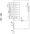
- FIGS. 13(a) to 13(b) show examples of the operation of the network switch 505 using the rule table 102b having the collision data CDATA described above.
- the MAC address MAC in Ethernet standard corresponds to the rule RULE.
- the MAC address instead of the MAC address, it may be configured to include the frame information defining the destination of the frame in the communication system 1 in the rule RULE.
- FIG. 13 (a) shows a first example of a process for retrieving whether or not a predetermined rule or MAC address is registered in the rule table 102b.
- the frame FRM of the first embodiment is replaced with the MAC address MAC.
- the network switch 505 can perform a predetermined process PRC according to the rule RULE registered in response to a particular MAC address MAC.
- FIG. 14A shows a first embodiment process of registering a predetermined MAC address MA in the rule table 102b as a rule RULE.
- FIG. 14 (b) shows a second example of a process of registering a predetermined MAC address MAC as a rule RULE in the rule table 102b.
- the MAC address MAC 12 is registered in the rule table 102b. Since the value of the data stored in the rule table 102b is different from that of the first example disclosed in FIG. 14 (a) , the processing to be applied is different. Details are described below.
- the entry lid EV and the collision bit CB are set to 1.
- the collision pointer valid CRPV is set to 1.
- FIG. 14 (c) shows a third example of a process of registering a predetermined MAC address MAC as a rule RULE in the rule table 102b.
- the MAC address MAC 12 is registered in the rule table 102b. Since the values of the data stored in the rule table 102b are different from those in the first example disclosed in FIG. 14(a) and the second example disclosed in FIG. 14(b) , the processing to be applied is different. Details are described below.
- FIG. 15A shows a first exemplary process of deleting a predetermined rule RULE from the rule table 102b.
- FIG. 15B shows a second exemplary process of deleting a predetermined rule RULE from the rule table 102b.
- the collision pointer CRP is referred to, and 3 is obtained as the collision pointer CRP.
- the data in the rule table 102b can be aligned in response to the elimination of the hash conflict, the number of times of resetting the address ADDR can be reduced, and the switching operation can be accelerated.
- FIG. 15C shows a third exemplary process of deleting a predetermined rule RULE from the rule table 102b.
- the collision pointer valid CRPV is 1 and that the read rule RULE and the rule RULE to be deleted do not coincide with each other at 22 and 42, respectively.
- the collision pointer CRP is subsequently referred to, and 3 is obtained as the collision pointer CRP.
- the reference information to the rule RULE that has been deleted and has become undefined can also be deleted.
- FIG. 15D shows a fourth exemplary process of deleting a predetermined rule RULE from the rule table 102b.
- the collision pointer valid CRPV is 1 and that the read rule RULE and the rule RULE to be deleted do not coincide with each other at 22 and 32, respectively.
- the collision pointer CRP is subsequently referred to, and 3 is obtained as the collision pointer CRP.
- the read rule RULE and the rule RULE to be deleted coincide with each other at 32.
- the collision bit CB is forcibly cleared to 0.
- the rule table 102b includes a collision data CDATA to provide a means for appropriately resetting the presence or absence of a collision of hash value HASH or the address ADDR when a collision of hash value HASH occurs. This reduces the number of re-sets of address ADDR and speeds up the retrieval of rule RULE.
- Another effect of the network switch 505b according to the third embodiment is as follows. That is, when creating or deleting a rule RULE, the data in the collision data CDATA is changed in response to the creation or deletion of the rule RULE. As a result, it is possible to reduce the frequency of occurrences of the collisions of the hash-value HASH and to speed up the search of the rules RULE.
- incrementing the address ADDR can be replaced by other methods. Examples include using a random number instead of 1 as the increment value, applying an arithmetic operation with an arbitrary number, making it possible to specify an arbitrary value by register setting or the like, selecting from a plurality of values according to the calculated value of the hash or the occurrence state of the collision, and combining them as appropriate.
Landscapes
- Engineering & Computer Science (AREA)
- Computer Networks & Wireless Communication (AREA)
- Signal Processing (AREA)
- Theoretical Computer Science (AREA)
- Physics & Mathematics (AREA)
- General Engineering & Computer Science (AREA)
- General Physics & Mathematics (AREA)
- Multimedia (AREA)
- Computer Security & Cryptography (AREA)
- Data Exchanges In Wide-Area Networks (AREA)
Applications Claiming Priority (1)
| Application Number | Priority Date | Filing Date | Title |
|---|---|---|---|
| JP2019188539A JP7330055B2 (ja) | 2019-10-15 | 2019-10-15 | ネットワーク処理装置、および、ネットワーク通信フレームの処理方法 |
Publications (1)
| Publication Number | Publication Date |
|---|---|
| EP3809639A1 true EP3809639A1 (fr) | 2021-04-21 |
Family
ID=72801330
Family Applications (1)
| Application Number | Title | Priority Date | Filing Date |
|---|---|---|---|
| EP20200478.4A Pending EP3809639A1 (fr) | 2019-10-15 | 2020-10-07 | Dispositif de traitement de réseau et procédé de traitement de réseaux de trames de communication |
Country Status (6)
| Country | Link |
|---|---|
| US (1) | US11516044B2 (fr) |
| EP (1) | EP3809639A1 (fr) |
| JP (1) | JP7330055B2 (fr) |
| KR (1) | KR20210044704A (fr) |
| CN (1) | CN112671940A (fr) |
| TW (1) | TW202118266A (fr) |
Families Citing this family (1)
| Publication number | Priority date | Publication date | Assignee | Title |
|---|---|---|---|---|
| JP7408033B2 (ja) * | 2021-11-10 | 2024-01-04 | 三菱電機株式会社 | 車載制御装置 |
Citations (3)
| Publication number | Priority date | Publication date | Assignee | Title |
|---|---|---|---|---|
| US20140006706A1 (en) * | 2012-06-27 | 2014-01-02 | Futurewei Technologies, Inc. | Ternary Content-Addressable Memory Assisted Packet Classification |
| JP2014042091A (ja) | 2012-08-21 | 2014-03-06 | Renesas Electronics Corp | パケット中継装置及びパケット中継方法 |
| JP2018148438A (ja) | 2017-03-07 | 2018-09-20 | ルネサスエレクトロニクス株式会社 | 通信システムおよび半導体装置 |
Family Cites Families (11)
| Publication number | Priority date | Publication date | Assignee | Title |
|---|---|---|---|---|
| WO2009110445A1 (fr) * | 2008-03-03 | 2009-09-11 | 日本電気株式会社 | Procédé de recherche d'adresse et dispositif de traitement de paquet |
| JP2011229093A (ja) | 2010-04-23 | 2011-11-10 | Hitachi Ltd | ネットワーク装置 |
| JP5954236B2 (ja) * | 2013-03-28 | 2016-07-20 | 日立金属株式会社 | ネットワーク中継装置 |
| US10063458B2 (en) * | 2013-10-13 | 2018-08-28 | Nicira, Inc. | Asymmetric connection with external networks |
| US9270592B1 (en) * | 2014-01-24 | 2016-02-23 | Google Inc. | Hash collision avoidance in network routing |
| US10057167B2 (en) * | 2014-04-09 | 2018-08-21 | Tallac Networks, Inc. | Identifying end-stations on private networks |
| CN104954200A (zh) * | 2015-06-17 | 2015-09-30 | 国家计算机网络与信息安全管理中心 | 一种网络数据包的多类型规则高速匹配方法及装置 |
| US9819587B1 (en) * | 2015-12-28 | 2017-11-14 | Amazon Technologies, Inc. | Indirect destination determinations to forward tunneled network packets |
| US10708272B1 (en) * | 2017-02-10 | 2020-07-07 | Arista Networks, Inc. | Optimized hash-based ACL lookup offload |
| US10230639B1 (en) * | 2017-08-08 | 2019-03-12 | Innovium, Inc. | Enhanced prefix matching |
| US10637778B1 (en) * | 2017-08-09 | 2020-04-28 | Open Invention Network Llc | Systems, methods and devices for scalable expansion of rules-based forwarding paths in network communications devices for distributed computing systems |
-
2019
- 2019-10-15 JP JP2019188539A patent/JP7330055B2/ja active Active
-
2020
- 2020-10-02 US US17/062,055 patent/US11516044B2/en active Active
- 2020-10-07 EP EP20200478.4A patent/EP3809639A1/fr active Pending
- 2020-10-12 KR KR1020200130901A patent/KR20210044704A/ko unknown
- 2020-10-13 TW TW109135282A patent/TW202118266A/zh unknown
- 2020-10-14 CN CN202011100034.XA patent/CN112671940A/zh active Pending
Patent Citations (3)
| Publication number | Priority date | Publication date | Assignee | Title |
|---|---|---|---|---|
| US20140006706A1 (en) * | 2012-06-27 | 2014-01-02 | Futurewei Technologies, Inc. | Ternary Content-Addressable Memory Assisted Packet Classification |
| JP2014042091A (ja) | 2012-08-21 | 2014-03-06 | Renesas Electronics Corp | パケット中継装置及びパケット中継方法 |
| JP2018148438A (ja) | 2017-03-07 | 2018-09-20 | ルネサスエレクトロニクス株式会社 | 通信システムおよび半導体装置 |
Also Published As
| Publication number | Publication date |
|---|---|
| US11516044B2 (en) | 2022-11-29 |
| US20210111922A1 (en) | 2021-04-15 |
| JP7330055B2 (ja) | 2023-08-21 |
| CN112671940A (zh) | 2021-04-16 |
| KR20210044704A (ko) | 2021-04-23 |
| JP2021064877A (ja) | 2021-04-22 |
| TW202118266A (zh) | 2021-05-01 |
Similar Documents
| Publication | Publication Date | Title |
|---|---|---|
| US9495479B2 (en) | Traversal with arc configuration information | |
| KR101615915B1 (ko) | 어드밴스드 피처를 갖는 정규 표현식 패턴에 대한 비결정성 유한 오토마톤 (nfa) 생성 | |
| US7949683B2 (en) | Method and apparatus for traversing a compressed deterministic finite automata (DFA) graph | |
| US8228908B2 (en) | Apparatus for hardware-software classification of data packet flows | |
| US8180803B2 (en) | Deterministic finite automata (DFA) graph compression | |
| US9154324B2 (en) | Method and filter system for filtering messages received via a serial data bus of a communication network by a user of the network | |
| US20140324900A1 (en) | Intelligent Graph Walking | |
| US8599859B2 (en) | Iterative parsing and classification | |
| CN103004158A (zh) | 具有可编程内核的网络设备 | |
| JP2001223749A (ja) | パケット分類エンジン | |
| JP2003196295A (ja) | ツリー型知識ベース検索のルックアップ・パフォーマンスを向上させる方法 | |
| US20110258694A1 (en) | High performance packet processing using a general purpose processor | |
| US7480300B2 (en) | Content addressable memory organized to share entries between different entities such as ports of a network unit | |
| Dharmapurikar et al. | Design and implementation of a string matching system for network intrusion detection using FPGA-based bloom filters | |
| EP3809639A1 (fr) | Dispositif de traitement de réseau et procédé de traitement de réseaux de trames de communication | |
| EP3288222B1 (fr) | Dispositif et procédé de filtrage de paquet | |
| US9703484B2 (en) | Memory with compressed key | |
| CN112437096B (zh) | 加速策略查找方法及系统 | |
| US20160105363A1 (en) | Memory system for multiple clients | |
| CN107544928B (zh) | 直接存储器访问控制装置和对此的运行方法 | |
| US20160103611A1 (en) | Searching memory for a search key | |
| CN116319510A (zh) | 矢量包处理转发方法 | |
| CN117278341A (zh) | Acl规则更新方法、装置、设备及存储介质 | |
| CN114492621A (zh) | 一种多域网包分类处理方法及装置 |
Legal Events
| Date | Code | Title | Description |
|---|---|---|---|
| PUAI | Public reference made under article 153(3) epc to a published international application that has entered the european phase |
Free format text: ORIGINAL CODE: 0009012 |
|
| STAA | Information on the status of an ep patent application or granted ep patent |
Free format text: STATUS: THE APPLICATION HAS BEEN PUBLISHED |
|
| AK | Designated contracting states |
Kind code of ref document: A1 Designated state(s): AL AT BE BG CH CY CZ DE DK EE ES FI FR GB GR HR HU IE IS IT LI LT LU LV MC MK MT NL NO PL PT RO RS SE SI SK SM TR |
|
| AX | Request for extension of the european patent |
Extension state: BA ME |
|
| STAA | Information on the status of an ep patent application or granted ep patent |
Free format text: STATUS: REQUEST FOR EXAMINATION WAS MADE |
|
| 17P | Request for examination filed |
Effective date: 20211013 |
|
| RBV | Designated contracting states (corrected) |
Designated state(s): AL AT BE BG CH CY CZ DE DK EE ES FI FR GB GR HR HU IE IS IT LI LT LU LV MC MK MT NL NO PL PT RO RS SE SI SK SM TR |
|
| STAA | Information on the status of an ep patent application or granted ep patent |
Free format text: STATUS: EXAMINATION IS IN PROGRESS |
|
| 17Q | First examination report despatched |
Effective date: 20230705 |